

Page 1
Operating Instructions
Bedienungsanleitung
Instructions de Service
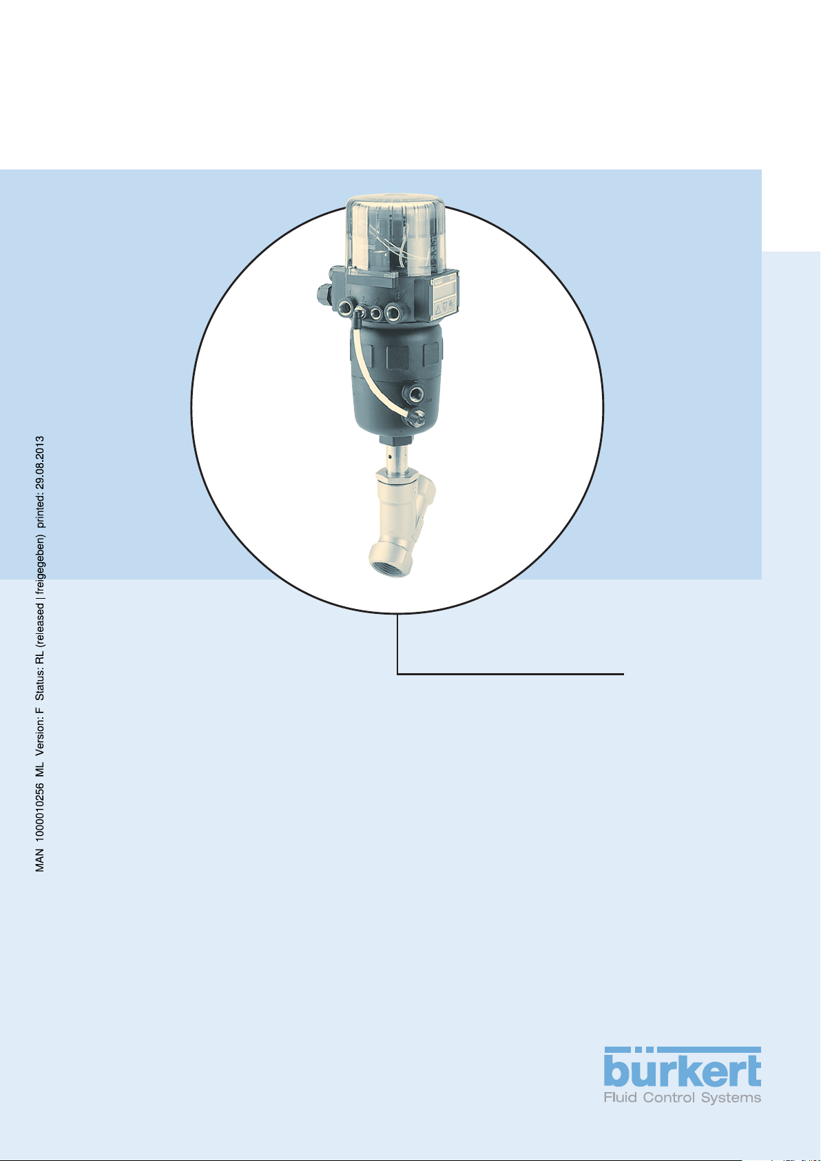
Type 2700
Piston controlled Y-valve
Actuator sizes 80 mm - 125 mm
Nominal diameter DN 13 - 65
Kolbengesteuertes Schrägsitzventil
Antriebsgrößen 80 mm - 125 mm
Nennweiten DN 13 - 65
Soupape de réglage à tête inclinée
commandée par piston
Tailles de mécanisme 80 mm - 125 mm
Piston section nominale DN 13 - 65
Page 2

We reserve the right to make technical changes without notice.
Technische Änderungen vorbehalten.
Sous resérve de modification techniques.
© 2000 Bürkert Werke GmbH & Co. KG
Operating Instructions 0507/08_EU-ML_00803794
Page 3

C
ONTENTS
Contents of the overall operating in-
structions for the piston controlled Y-valve
Type 2700
GENERAL INFORMATION.................................................................................................................................................................................................... 3
Symbols
Safety information ................................................................................................................................................................................................................... 4
Scope of delivery ..................................................................................................................................................................................................................... 4
Warranty conditions............................................................................................................................................................................................................ 4
TECHNICAL DATA........................................................................................................................................................................................................................... 5
Construction of the control valve ..................................................................................................................................................................... 6
Media ......................................................................................................................................................................................................................................................... 6
COMMISSIONING................................................................................................................................................................................................................................. 7
Installation
Pneumatic installation...................................................................................................................................................................................................... 8
................................................................................................................................................................................................................................................ 4
......................................................................................................................................................................................................................................... 8
english
MAINTENANCE AND SERVICING.......................................................................................................................................................................... 9
Faults
Replacement of control cone............................................................................................................................................................................. 10
Spare parts sets .................................................................................................................................................................................................................... 11
...................................................................................................................................................................................................................................................... 10
2700 - 1
Page 4
C
ONTENTS
english
2 - 2700
Page 5

G
ENERAL INFORMATION
GENERAL
INFORMATION
english
Symbols ................................................................................................................................................................................................................................................ 4
Safety information ................................................................................................................................................................................................................. 4
Scope of delivery ..................................................................................................................................................................................................................... 4
Warranty conditions
............................................................................................................................................................................................................ 4
2700 - 3
Page 6
G
ENERAL INFORMATION
Symbol
The following symbol are used in these operating instructions:
marks a working step which must be performed
ATTENTION!
NOTE
Safety information
english
Please observe the notes int hese operating instructions as well as the service conditions and permissible data which are
specified in the data sheets for the valve Type 2700 with pneumatic drive and the Top
function flawlessly and remain operable for a long time:
• Follow general technical rules when planning the application and operation of the unit!
• Installation and maintenance may only be performed by technical personnel provided with suitable tools!
• Note the accident prevention and safety precautions applicable during operation and maintenance of the unit!
• Always switch off the power supply before working on the system!
• Take suitable measures to prevent inadvertent operation or impermissible influences!
• Ensure a defined and controlled re-start of the process following an interruption of the electrical or pneumatic supply!
• Take the safety notes from the electrical part of the Top
indicates information, which if not observed can result in harmfull effects on the health or the serviceability
of the unit.
Indicates important additional information, tips and recommendations.
Control,
in order that the device will
Control
operating instructions.
• We cannot accept any liability if these instructions are ignored or impermissible interventions are made in the unit and the
warranty also becomes invalid on units and accessories!
Scope of delivery
Immediately after receipt of a shipment, make sure that the contents are undamaged and match the scope of delivery stated
on the packing slip.
If there are discrepancies, please contact immediately your Bürkert branch or our customer service:
Warranty conditions
This document contains no warranty promises. We refer in this connection to our General Conditions of Sale and Business.
The condition for the warranty is use of the unit for the intended purpose under the specified under the specified application
conditions.
ATTENTION!
The warranty extends only to absence of faults in the valve Type 2700 with pneumatic drive and the
To p
Control
result of the failure or incorrect functioning of the device.
Bürkert Fluid Control Systems
Service Department
Chr.-Bürkert-Str. 13-17
D-76453 Ingelfingen
Tel.: (07940) 10-111
Fax: (07940) 10-448
E-Mail: info@de.buerkert.com
. No liability will, however, be accepted for subsequent damage of any kind that may arise as a
4 - 2700
Page 7

T
ECHNICAL DATA
TECHNICAL DATA
Construction of the control valve ................................................................................................................................................................... 6
english
Media ......................................................................................................................................................................................................................................................... 6
2700 - 5
Page 8
T
ECHNICAL DATA
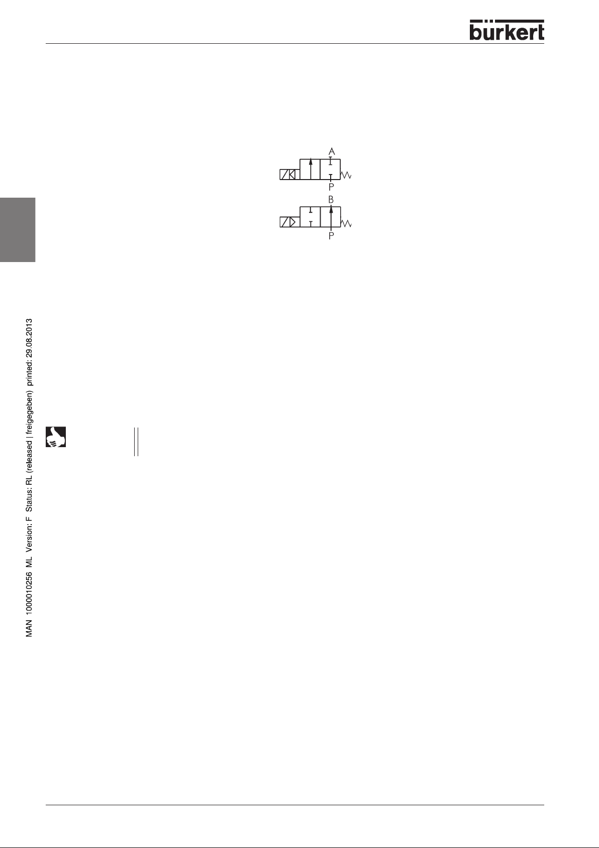
Construction of the control valve
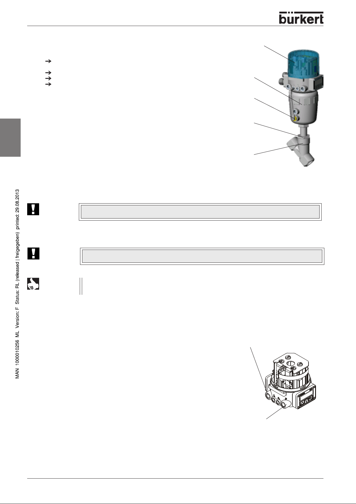
2/2-way piston controlled valve with control cone and Y-housing
Control function A
(closed by spring force in rest position)
Control function B
(open in rest position)
english
Media
Drive unit material: PA (polyamide)
Housing material: stainless steel 316L
Seal materials: steel/steel (1.4571) or PTFE/steel
Liquid and gaseous media that do not attack the housing and seal materials.
Control medium: instrument air, class 3 according to DIN ISO 8573-1
NOTE
The approved operating pressures and media temperatures are to be taken from the data sheet or rating
plate. With regard to the permissible seat leakage, the values given in DIN EN 1349 are complied with,
whereby for the steel/steel seal, leakage class IV and for the PTFE/steel leakage class VI apply.
6 - 2700
Page 9

C
OMMISSIONING
COMMISSIONING
Installation of the valve........................................................................................................................................................................................................ 8
english
Pneumatic installation .......................................................................................................................................................................................................... 8
2700 - 7
Page 10
C
OMMISSIONING
Installation of the valve
May be installed in any position, but preferably with the drive unit above.
Observe the flow direction - general rule for control valves: flow input under
seat!
Clean the piping of contamination!
Before connecting the valve housing, take care that piping is aligned!
In the case of weld-on housings, be sure to remove the drive unit before
welding.
Procedure:
1. Remove the electrical and pneumatic supplies from the Top
2. Pull off the pneumatic hose between Top
connection of drive unit.
3. Control function A: Pressurize the lowr port of the actuator with
compressed air (6 bar), so that the control cone is lifted from the valve
seat and is not damaged.
Control function B: With control function B, no compressed air must be
english
ATTENTION!
applied for this purpose.
4. Remove the actuator in the open valve position by unscrewing the nipple
from the housing.
5. Before reinstalling the actuator (in the open valve position), grease the
nipple thread with stainless steel lubricant, e. g. Klüberpaste UH1 96-402
from Messrs. Klüber.
6. Replace the graphite seal.
To p
Control
actuator
lower
control port
Control
Control
and drive unit at control
For special applications such as for oxygen and analysis, use only the approved lubricants.
.
threaded
nipple
housing
7. After tightening the threaded nipple, align the control ports by turning the actuator.
ATTENTION!
The valve must be for this in the opened position.
NOTE
When using in an aggressive environment, you are advised to connect pneumatic hoses to all free control
connections and place their other ends in a neutral atmosphere.
Pneumatic installation
The control valve is driven by compressed air via the Top
Control medium: instrument air,
££
£ Remove the protective caps from the ports.
££
➔➔
➔ Apply the supply pressure to port ”1”.
➔➔
The supply pressure necessary for complete opening or closing of the valve
may lie between the minimum values of 3 and 6 bar, depending on the
actuator. The permissible maximum value for the control pressure is 7 bar. The
values for the pressure supply are given under p
control valve.
Control
Class 3 to DIN ISO 8573-1
on the rating plate of each
Pilot
Supply pressure connector
.
(inscription: 1)
8 - 2700
➔➔
➔ Attach the exhaust line or silencer to port ”3”.
➔➔
Outlet air connector
(inscription: 3)
Fluidic connections of the
TopControl Continuous
Page 11
M
AINTENANCE AND SERVICING
MAINTENANCE AND
SERVICING
Faults................................................................................................................................................................................................................................................................................ 10
Replacement of control cone ................................................................................................................................................................................................................. 10
Spare parts sets ................................................................................................................................................................................................................................................... 11
english
2700 - 9
Page 12
M
AINTENANCE AND SERVICING
Faults
ATTENTION!
Repairs to the actuator may only be carried out in the factory. Contact your Bürkert branch or our
Customer Service directly:
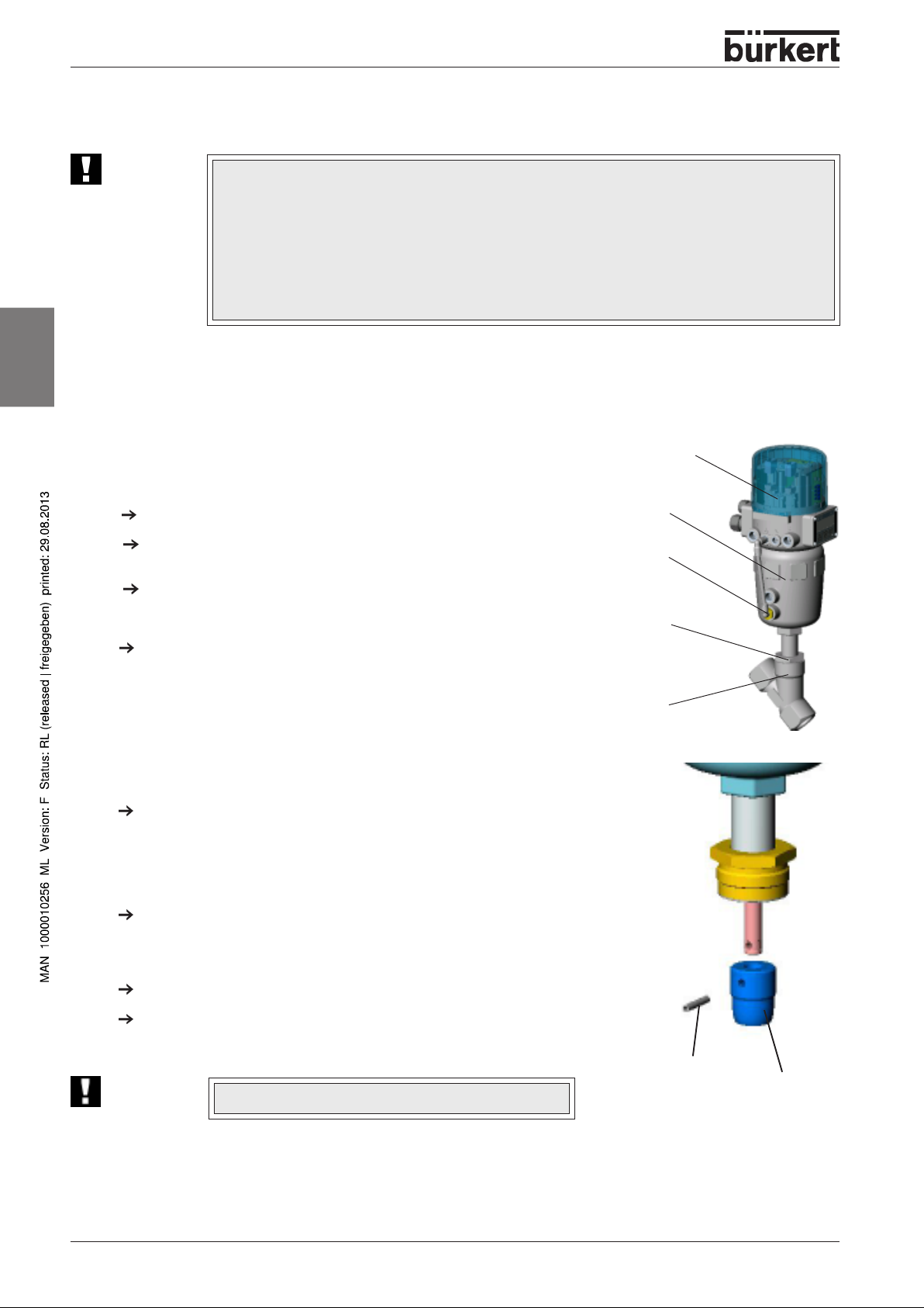
Replacement of the control cone
english
On the fluidic side is it possible to exchange the control cone if it becomes worn or damaged. For this purpose the drive unit
must be disassembled from the housing.
Disassembly:
Remove the electrical and pneumatic supplies from the Top
Pull off the pneumatic hose between Top
connection of drive unit.
Control function A:
Pressurize the lower control port of the actuator with compressed air (6 bar), so
that the control cone is lifted from the valve seat and is not damaged.
Bürkert Fluid Control Systems
E-Mail: info@de.buerkert.com
Control
and drive unit at control
Service Department
Chr.-Bürkert-Str. 13-17
D-76453 Ingelfingen
Tel.: (07940) 10-111
Fax: (07940) 10-448
Control
.
To p
Control
actuator
lower
control port
threaded nipple
Control function B:
With control function B, no compressed air must be applied for this purpose.
Remove the actuator in the open valve position by unscrewing the nipple from the
housing.
Replacing the control cone
Knock out the dowel pin with a suitable driver.
Driver diameter:
up to DN 25 Ø 4 mm
from DN 32 Ø 5 mm
Pull off the control cone with aid of two metal strips of equal height that are clamped to
the left and right of the spindle between the control cone and the threaded nipple of the
drive unit. To pull off the control cone, apply compressed air (approx. 6 bar) to the lower
control connection of the drive.
Push the new control cone over the end of the spindle.
Align the bores.
ATTENTION!
Do not damage the sealing surface or the control contour!
housing
Dowel pin
Control cone
10 - 2700
Page 13
M
AINTENANCE AND SERVICING
Support the control cone at its cylindrical part with the aid of a V-block or the like.
Carefully knock the dowel pin into the bore with a hammer.
Bring the dowel pin into a central position relative to the spindle axis (knock in as far as the end of the recess).
Assembly
Assembly is carried out in the reverse sequence to disassembly.
Before reinstalling the actuator (in the open valve position), grease the nipple thread with stainless steel lubricant, e.g.
Klüberpaste UH1 96-402 from Messrs. Klüber and replace the graphite seal.
ATTENTION!
ATTENTION!
The valve must be for this in the opened position.
For special applications such as for oxygen and analysis, use only the approved lubricants.
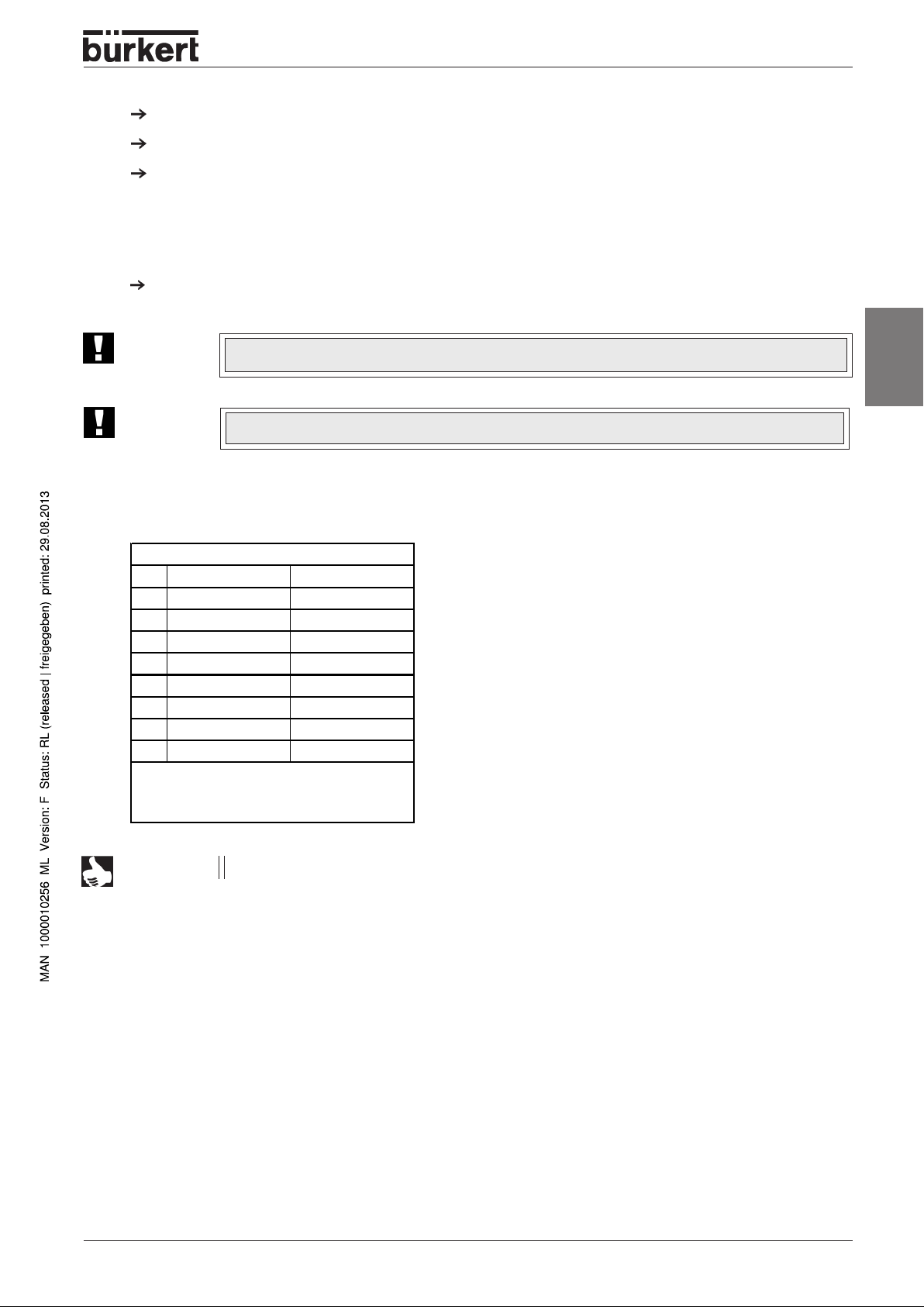
Spare parts sets
Control cone set
DN Steel/Steel PTFE/steel
Order no. Order no.
13 149 790 149 927
20 149 921 149 928
25 149 922 149 929
32 149 923 149 930
40 149 924 149 931
50 149 925 149 932
65 149 926 149 933
Contains:
Control cone, dowel pin, graphite seal,
lubricant
english
NOTE
Spare parts sets for special versions are available on request (e.g. oxygen or analysis versions, etc.).
2700 - 11
Page 14

M
AINTENANCE AND SERVICING
english
12 - 2700
Page 15

M
AINTENANCE AND SERVICING
english
2700 - 13
Page 16

M
AINTENANCE AND SERVICING
english
14 - 2700
Page 17

I
NHALT
Inhaltsverzeichnis
der Gesamtbedienungsanleitung des
kolbengesteuerten Schrägsitzregelventils
Typ 2700
ALLGEMEINE HINWEISE................................................................................................................................................................................................... 17
Darstellungsmittel
Sicherheitshinweise .......................................................................................................................................................................................................... 18
Lieferumfang.............................................................................................................................................................................................................................. 18
Garantiebestimmungen ............................................................................................................................................................................................. 18
TECHNISCHE DATEN............................................................................................................................................................................................................ 19
Aufbau des Regelventils............................................................................................................................................................................................. 20
Medien ................................................................................................................................................................................................................................................. 20
INBETRIEBNAHME...................................................................................................................................................................................................................... 21
Einbau
Pneumatische Installation ...................................................................................................................................................................................... 22
.................................................................................................................................................................................................................................................. 22
.............................................................................................................................................................................................................. 18
deutsch
INSTANDHALTUNG UND WARTUNG.......................................................................................................................................................... 23
Störungen
Austausch des Regelkegels ................................................................................................................................................................................ 24
Ersatzteilsätze ........................................................................................................................................................................................................................... 25
...................................................................................................................................................................................................................................... 24
2700 - 15
Page 18

I
NHALT
deutsch
16 - 2700
Page 19

A
ALLGEMEINE
HINWEISE
LLGEMEINE HINWEISE
deutsch
Darstellungsmittel.............................................................................................................................................................................................................. 18
Sicherheitshinweise ........................................................................................................................................................................................................ 18
Lieferumfang................................................................................................................................................................................................................................ 18
Garantiebestimmungen
............................................................................................................................................................................................. 18
2700 - 17
Page 20

A
LLGEMEINE HINWEISE
Darstellungsmittel
In dieser Betriebsanleitung werden folgende Darstellungsmittel verwendet:
markiert einen Arbeitsschritt, den Sie ausführen müssen
ACHTUNG!
HINWEIS
kennzeichnet Hinweise, bei deren Nichtbeachtung Ihre Gesundheit oder die Funktionsfähigkeit des Gerätes gefährdet ist
kennzeichnet wichtige Zusatzinformationen, Tips und Empfehlungen
Sicherheitshinweise
Bitte beachten Sie die Hinweise dieser Betriebsanleitung sowie die Einsatzbedingungen und zulässigen Daten, die in den
Datenblättern des Ventils mit pneumatischem Antrieb und des Top
tioniert und lange einsatzfähig bleibt:
• Halten Sie sich bei der Einsatzplanung und dem Betrieb des Gerätes an die allgemeinen Regeln der Technik!
deutsch
• Installation und Wartungsarbeiten dürfen nur durch Fachpersonal und mit geeignetem Werkzeug erfolgen!
• Beachten Sie die geltenden Unfallverhütungs- und Sicherheitsbestimmungen während des Betriebes und der Wartung des
Gerätes!
• Schalten Sie vor Eingriffen in das System in jedem Fall die Spannung ab!
• Beachten Sie, daß in Systemen, die unter Druck stehen, Leitungen und Ventile nicht gelöst werden dürfen!
• Treffen Sie geeignete Maßnahmen, um unbeabsichtigtes Betätigen oder unzulässige Beeinträchtigung auszuschließen!
• Gewährleisten Sie nach einer Unterbrechung der elektrischen oder pneumatischen Versorgung einen definierten und
kontrollierten Wiederanlauf des Prozesses!
Control
spezifiziert sind, damit das Gerät einwandfrei funk-
• Entnehmen Sie die Sicherheitshinweise zum elektrischen Teil der Bedienungsanleitung des Top
• Bei Nichtbeachtung dieser Hinweise und unzulässigen Eingriffen in das Gerät entfällt jegliche Haftung unsererseits,
ebenso erlischt die Garantie auf Geräte und Zubehörteile!
Lieferumfang
Überzeugen Sie sich unmittelbar nach Erhalt der Sendung, daß der Inhalt nicht beschädigt ist und mit dem auf dem beigelegten Packzettel angegebenen Lieferumfang übereinstimmt.
Bei Unstimmigkeiten wenden Sie sich bitte umgehend an an Ihre Bürkert-Niederlassung oder an unseren Kundenservice:
Garantiebestimmungen
Diese Druckschrift enthält keine Garantiezusagen. Wir verweisen hierzu auf unsere allgemeinen Verkaufs- und Geschäftsbedingungen. Voraussetzung für die Garantie ist der bestimmungsgemäße Gebrauch des Gerätes unter Beachtung der spezifizierten Einsatzbedingungen.
ACHTUNG!
Die Gewährleistung erstreckt sich nur auf die Fehlerfreiheit des Ventils Typ 2700 mit pneumatischem
Antriebund des Top
durch Ausfall oder Fehlfunktion des Gerätes entstehen könnten.
Control
Bürkert Steuer- und Regelungstechnik
Chr.-Bürkert-Str. 13-17
Service-Abteilung
D-76453 Ingelfingen
Tel.: (07940) 10-111
Fax: (07940) 10-448
E-Mail: info@de.buerkert.com
Control
. Es wird jedoch keine Haftung übernommen für Folgeschäden jeglicher Art, die
18 - 2700
Page 21

T
ECHNISCHE DATEN DES VENTILS
TECHNISCHE DATEN
Aufbau des Regelventils........................................................................................................................................................................................... 20
Medien ................................................................................................................................................................................................................................................... 20
deutsch
2700 - 19
Page 22

T
ECHNISCHE DATEN DES VENTILS
Aufbau des Regelventils
2/2-Wege-Kolbensteuerventil mit Regelkegel und Geradsitzgehäuse
Steuerfunktion A
(in Ruhestellung durch Federkraft geschlossen)
Steuerfunktion B (in Ruhestellung geöffnet)
Antriebswerkstoff: PA (Polyamid)
Gehäusewerkstoff: Edelstahl 316L
Dichtwerkstoffe: Stahl/Stahl (1.4571) oder PTFE/Stahl
deutsch
Medien
Flüssige u. gasförmige Medien, die den Gehäuse- und Dichtwerkstoff nicht angreifen.
Steuermedium: Instrumentenluft, Klasse 3 nach DIN ISO 8573-1
HINWEIS
Die zugelassenen Betriebsdrücke und Medientemperaturen sind dem Datenblatt bzw. dem Typschild zu
entnehmen. Hinsichtlich der zulässigen Sitzleckage werden die in der DIN EN 1349 angegebenen Werte
eingehalten, wobei für die Stahl/Stahl-Abdichtung die Leckageklasse IV und für die PTFE/Stahl-Adichtung
die Leckageklasse VI zutrifft.
20 - 2700
Page 23

I
NBETRIEBNAHME DES VENTILS
INBETRIEBNAHME
Einbau des Ventils..................................................................................................................................................................................................................... 22
Pneumatische Installation ........................................................................................................................................................................................... 22
deutsch
2700 - 21
Page 24

I
NBETRIEBNAHME DES VENTILS
Einbau des Ventils
Einbaulage beliebig, bevorzugt Antrieb nach oben.
Beachten Sie die Durchflußrichtung, bei Regelventilen gilt generell: An
strömung unter Sitz!
Säubern Sie die Rohrleitungen von Verunreinigungen!
Achten Sie vor Anschluß des Ventilgehäuses auf fluchtende Rohrleitungen!
Entfernen Sie bei Schweißgehäusen den Antrieb unbedingt vor dem Einschweißen des Gehäuses.
Vorgehensweise:
1. Entfernen Sie die elektrische u. pneumatische Versorgung
2. Ziehen Sie den Pneumatikschlauch zwischen Top
3. Steuerfunktion A: Beaufschlagen Sie den unteren Steueranschluss des
4. Entfernen Sie den Antrieb in offener Ventilstellung durch Losschrauben des
deutsch
5. Fetten Sie vor Wiedereinbau des Antriebes (in offener Ventilstellung) das
6. Erneuern Sie die Graphitdichtung.
vom Top
Antrieb am Steueranschluss des Antriebes ab.
Antriebes mit Druckluft (6 bar), damit der Regelkegel vom Ventilsitz abhebt
und nicht beschädigt wird.
Steuerfunktion B: Bei Steuerfunktion B muss keine Druckluft angelegt
werden.
Nippels vom Gehäuse.
Nippelgewinde mit Edelstahlschmierstoff ein, z.B. Klüberpaste UH1 96-402
der Firma Klüber.
Control
.
Control
und
To p
Control
Antrieb
unterer
Steueranschluss
GewindeNippel
Gehäuse
ACHTUNG!
7. Richten Sie nach Festziehen des Nippels die Steueranschlüsse durch Verdrehen
des Antriebes aus.
ACHTUNG!
HINWEIS
Verwenden Sie bei spezifischen Anwendungen, z. B. Sauerstoff-, Analyseanwendungen,
nur zugelassene Schmierstoffe.
Das Ventil muss sich hierzu in der geöffneten Stellung befinden.
Bei Einsatz in aggressiver Umgebung empfehlen wir, sämtliche freien Pneumatikanschlüsse mit Hilfe eines Pneumatikschlauches in neutrale Atmosphäre abzuleiten.
Pneumatische Installation
Das Regelventil wird über das Top
Steuermedium: Instrumentenluft,
££
£ Entfernen Sie die Schutzkappen von den Anschlüssen
££
➔➔
➔ Legen Sie den Versorgungsdruck an Anschluss ”1”
➔➔
Der für das vollständige Öffnen bzw. Schließen des Ventils erforderliche
Versorgungsdruck kann je nach Antrieb, zwischen den Minimalwerten von 3
bar bis 6 bar liegen. Der zulässige Maximalwert für den Steuerdruck beträgt 7
bar. Die Werte für die Druckversorgung sind unter p
jeweiligen Regelventils angegeben.
➔➔
➔ Montieren Sie Abluftleitung oder Schalldämpfer an Anschluss ”3”.
➔➔
Control
mit Druckluft angesteuert.
Klasse 3 nach DIN ISO 8573-1
auf dem Typschild des
Pilot
Versorgungsdruckanschluss
(Beschriftung: 1)
22 - 2700
Abluftanschluss
(Beschriftung: 3)
Fluidische Anschlüsse des
TopControl Continuous
Page 25

I
NSTANDHALTUNG UND WARTUNG DES VENTILS
INSTANDHALTUNG
UND
WARTUNG
deutsch
Störungen .................................................................................................................................................................................................................................................................... 24
Austausch des Regelkegels ..................................................................................................................................................................................................................... 24
Ersatzteilsätze für Standardgeräte .................................................................................................................................................................................................. 25
2700 - 23
Page 26

I
NSTANDHALTUNG UND WARTUNG DES VENTILS
Störungen
Mögliche Störungen seitens der Ansteuerung sind in der Bedienungsanleitung des Top
ACHTUNG!
Reparaturen am Antrieb dürfen nur im Werk durchgeführt werden. Wenden Sie sich hierzu an Ihre Bürkert
Niederlassung oder direkt an unseren Kundenservice:
Austausch des Regelkegels
Auf der fluidischen Seite besteht die Möglichkeit bei Verschleiß oder bei Beschädigung den Regelkegel zu tauschen. Hierzu
muß der Antrieb vom Gehäuse demontiert werden.
Demontage
deutsch
Entfernen Sie die elektrische u. pneumatische Versorgung vom Top
Ziehen Sie den Pneumatikschlauch zwischen Top
Steueranschluß des Antriebes ab.
Steuerfunktion A:
Beaufschlagen Sie den unteren Steueranschluß des Antriebes mit Druckluft (6
bar), damit der Regelkegel vom Ventilsitz abhebt und nicht beschädigt wird.
Control
Bürkert Steuer- und Regelungstechnik
Control
Service-Abteilung
Chr.-Bürkert-Str. 13-17
D-76453 Ingelfingen
Tel.: (07940) 10-111
Fax: (07940) 10-448
E-Mail: info@de.buerkert.com
Control
.
und Antrieb am
aufgeführt.
To p
Control
Antrieb
unterer
Steueranschluss
Gewinde-
Steuerfunktion B:
Bei Steuerfunktion B muss keine Druckluft angelegt werden.
Entfernen Sie den Antrieb in offener Ventilstellung durch Losschrauben des
Nippels vom Gehäuse.
Regelkegel tauschen
Klopfen Sie den Spannstift mit einem passenden Splinttreiber heraus.
Durchmesser des Splinttreibers:
bis DN 25 Ø 4 mm
ab DN 32 Ø 5 mm
Ziehen Sie den Regelkegel mit Hilfe zweier gleich hoher Metallleisten ab, die links und
rechts der Spindel zwischen den Regelkegel und den Gewindenippel des Antriebes
geklemmt werden. Geben Sie zum Abziehen des Regelkegels auf den unteren Steueranschluß des Antriebes Druckluft (6 bar).
Stecken Sie den neuen Regelkegel auf das Spindelende.
Richten Sie die Bohrungen zueinander aus.
ACHTUNG!
Dichtfläche und Regelkontur des Regelkegels dürfen nicht
beschädigt werden!
Gehäuse
Spannstift
Regelkegel
24 - 2700
Page 27

I
NSTANDHALTUNG UND WARTUNG DES VENTILS
Stützen Sie den Regelkegel an seinem zylindrischen Teil mit Hilfe eines Prismas oder ähnlichem ab.
Setzen Sie den Spannstift an und klopfen Sie ihn vorsichtig mit dem Hammer ein.
Bringen Sie den Spannstift in zur Spindelachse gesehen mittige Lage (klopfen Sie ihn bis zum Ende der Ansenkung ein).
Montage
Der Zusammenbau erfolgt in umgekehrter Reihenfolge wie die Demontage
Fetten Sie vor Wiedereinbau des Antriebes (in offener Ventilstellung) das Nippelgewinde mit Edelstahlschmierstoff ein, z.B.
Klüberpaste UH1 96-402 der Firma Klüber, und erneuern Sie die Graphitdichtung.
ACHTUNG!
ACHTUNG!
Das Ventil muss sich hierzu in der geöffneten Stellung befinden.
Verwenden Sie bei spezifischen Anwendungen, z.B. Sauerstoff-, Analyseanwendungen nur zugelassene
Schmierstoffe.
Ersatzteilsätze für Standardgeräte
Regelkegelsatz
DN Stahl/Stahl PTFE/Stahl
Best.-Nr. Best.-Nr .
13 149 790 149 927
20 149 921 149 928
25 149 922 149 929
32 149 923 149 930
40 149 924 149 931
50 149 925 149 932
65 149 926 149 933
Beinhal tet:
Regelkegel, Spannstift, Graphitdi chtung,
Schmierstoff
deutsch
HINWEIS
Ersatzteilsätze für Sonderausführungen erhalten Sie auf Anfrage ( z. B. Sauerstoff-, Analyseausführungen)
usw. auf Anfrage)
2700 - 25
Page 28

I
NSTANDHALTUNG UND WARTUNG DES VENTILS
deutsch
26 - 2700
Page 29

T
ABLE DES MATIÈRES
Table des matières des instructions de
service complètes de la soupape de
réglage à tête inclinée commandée par
piston type 2700
INDICATIONS GÉNÉRALES ......................................................................................................................................................................................... 29
Symboles graphiques
Indications de sécurité .................................................................................................................................................................................................. 30
Volume de livraison.......................................................................................................................................................................................................... 30
Clauses de garantie ......................................................................................................................................................................................................... 30
CARACTÉRISTIQUES TECHNIQUES ............................................................................................................................................................ 31
Structure de la soupape de réglage ........................................................................................................................................................... 32
Fluides................................................................................................................................................................................................................................................. 32
MISE EN SERVICE......................................................................................................................................................................................................................... 33
Montage de la soupape
Connexion pneumatique .......................................................................................................................................................................................... 34
................................................................................................................................................................................................... 30
............................................................................................................................................................................................... 34
français
REMISE EN ETAT ET ENTRETIEN....................................................................................................................................................................... 35
Pannes
Remplacement du pointeau de réglage ................................................................................................................................................ 36
Jeux de pièces de rechange ................................................................................................................................................................................ 37
................................................................................................................................................................................................................................................ 36
2700 - 27
Page 30

T
ABLE DES MATIÈRES
français
28 - 2700
Page 31

I
NDICATIONS GÉNÉRALES
INDICATIONS
GÉNÉRALES
Symboles graphiques ................................................................................................................................................................................................... 30
Indications de sécurité .................................................................................................................................................................................................. 30
Volume de livraison.......................................................................................................................................................................................................... 30
Clauses de garantie
......................................................................................................................................................................................................... 30
français
2700 - 29
Page 32

I
NDICATIONS GÉNÉRALES
Symboles graphiques
Les symboles suivants sont utilisés dans ce mode d'emploi:
indique une operation que vous devez exécuter
ATTENTION!
REMARQUE
Signale des consignes, dont l'inobservation peut mettre en danger vorte santé ou altérer la capacité de
fonctionnement de l'appareil.
signale des informations complémentaires importantes, des conseils ou des recommandation
Indications de sécurité
Veuillez observer les indications de ces instructions de service de même que les conditions de mise en oeuvre et données
admisibles spécifiées das les fiches techniques de la soupape à mécanisme pneumatique et du Top
fonctionne parfaitement et reste en service longtemps:
• Respectez les règles générales de la technique lors du planning d'utilisation et de l'exploitation de l'appareil!
• L'installation et les travaux d'entretien ne doivent être effectués que par des spécialistes et au moyen d'un outillage
approprié!
• Durant l'exploitation et l'entretien de l'appareil, observez les prescriptions applicables en matière de prévention des
accidents et de sécurité !
français
• Couper chaque fois l'alimentation électrique avant toute intervention dans le système!
• Observer que les conduites et les vannes des systèmes se trouvant sous pression ne doivent pas être démontées!
• Prenez les mesures appropriées pour exclure un actionnement involontaire ou un préjudice inadmissible!
Control
afin que l'appareil
• Assurez un redémarrage défini et contrôlé du processus après une interruption de l'alimentation électrique ou
pneumatique!
• Les consignes de sécurité de la partie électrique figurent dans les instructions de service du Top
• En cas de non-observation de ces consignes ou d'interventions prohibées sur l'appareil, nous déclinons toute
responsabilité, et la garantie sur l'appareil et les accessoires devient alors caduque!
Fourniture
Contrôler dès réception de l'envoi que le contenu n'a subi aucun dommage et qu'il correspond bien à la fourniture figurant sur
le bordereau d'envoi.
En cas de non concordance, s'adresser immédiatement à votre succursale Bürkert ou à notre service après vente
Clauses de garantie
Ce document ne contient aucune promesse de garantie. Nous renvoyons à nos conditions générales de vente. La garantie
n'est accordée, qu'à condition que l'appareil soit utilisé conformément aux prescriptions et en respectant les conditions
d'utilisation spécifiées.
Bürkert Steuer- und Regelungstechnik
Chr.-Bürkert-Str. 13-17
Service-Abteilung
D-76453 Ingelfingen
Tel.: (07940) 10-111
Fax: (07940) 10-448
E-Mail: info@de.buerkert.com
Control
.
ATTENTION!
30 - 2700
La garantie ne s'étend que sur l'absence de défaut de la soupape type 2700 avec connexion du
mécanisme pneumatique du Top
toute nature qui seraient consécutifs à une défaillance ou un mauvais fonctionnement de l'appareil.
Control
.Toute responsabilité est cependant déclinée pour les dégâts de
Page 33

C
ARACTÉRISTIQUES TECHNIQUES
CARACTÉRISTIQUES
TECHNIQUES
Structure de la soupape de réglage ......................................................................................................................................................... 32
Fluides................................................................................................................................................................................................................................................... 32
français
2700 - 31
Page 34

C
ARACTÉRISTIQUES TECHNIQUES
Structure de la soupape de réglage
Soupape commandée par piston 2/2 voies à pointeau de réglage et boîtier à tête inclinée
Fonction de commande A
(fermée par ressort en position de repos)
Fonction de commande B
(ouverte en position de repos)
Marière du mécanisme: PA (polyamide)
Matière du boîtier: Acier inoxydable 316L
Matière d'étanchéité: acier/acier (1.4571) ou PTFE/acier
Fluides
Fluides liquides et gazeux n'attaquant ni le boîtier, ni la matière d'étanchéité.
français
Air de pilotage: air pour instrument, classe 3 selon DIN ISO 8573-1
REMARQUE
Les pressions de service et température des fluides autorisées figurent sur les fiches techniques ou la
plaque signalétique. En ce qui concerne les fuites de siège admissibles, les valeurs indiquèes das la norme
DIN EN 1349 sont respectées, compte entu que pour l'étanchéité acier/acier la classe de fuite IV et pour
celle PTFE/acier, la classe VI s'appliquent.
32 - 2700
Page 35

M
ISE EN SERVICE
MISE EN SERVICE
Montage de la soupape.................................................................................................................................................................................................... 34
Installation pneumatique............................................................................................................................................................................................... 34
français
2700 - 33
Page 36

M
ISE EN SERVICE
Montage de la soupape
Position de montage quelconque, de préférence mécansime d'actionnement vers le
haut.
Tenir compte du sens du débit, chez les soupapes de réglage, l'afflux a lieu
sous le siège.
Nettoyer les conduites des impuretés!
Veiller avant de raccorder le boîtier de la soupape au bon alignement des
conduites!
Dans le cas de boîtiers de mécanisme à souder, enlever impérativement
auparavant le mécanisme avant de souder.
Manière de procéder:
1. Enlever l'alimentation électrique et pneumatique du Top
2. Ôter en tirant le tuyau souple pneumatique entre le Top
mécanisme d'actionnement au raccordement de commande de ce dernier.
3. Fonction de commande A:
Charger d'air comprimé (6 bars) le raccord inférieur de commande du
mécanisme afin que le pointeau de réglage se soulève du siège et ne soit
pas endommagé.
Fonction de commande B:
Pas de chargement d'air comprimé pour la fonction B.
4. Enlever le mécanisme en position ouverte de la soupape, en dévissant le
raccord du boîtier.
5. Avant de remoter le mécanisme (en position ouverte de la soupape),
graisser le raccord à vis avec un lubrifiant pour acier fin, p. ex. pâte Klüber
UH1 96-402 de la maison Klüber.
6. Renouveler le joint graphite.
Control
Control
.
et le
To p
Control
Mécanisme
Raccord inférieur
de commande
Raccord à vis
Boîtier
ATTENTION!
français
7. Aligner les raccords de commande en tournant le mécanisme après avoir serré à fond le raccord à vis.
ATTENTION!
REMARQUE
Installation pneumatique
La soupape de réglage est excité par le Top
Fluide de commande: air instrumental
££
£ Enlever les capuchons protecteurs des raccords.
££
➔➔
➔ Mettre la pression d'alimentation au raccord ”1”
➔➔
La pression d'alimentation nécessaire à l'ouverture et la fermeture complète
de la soupape peut se situer suivant le mécanisme de commande entre les
valeurs minimales de 3 à 6 bars. La valeur maximale admissible pour le
pression de commande est de 7 bars. Les valeurs de la pression
d'alimentation sont indiquées par p
de réglage en question.
➔➔
➔ Monter la conduite d'air d'échappement ou un silencieux au raccord ”3”.
➔➔
Dans le cas d'applications spécifiques p.ex. applications d'analyse, d'oxygène, utiliser uniquement des
lubrifiants agréés.
La soupape doit également se trouver à cet effet en position ouverte.
En cas d'utilisation dans un environnement afressif, nous recommandons de dévier tous les
raccordements pneumatiques libres dans une atmosphère neutre à l'aide d'un tuyau flexible pneumatique.
Control
avec de l'air comprimé.
classe 3 pour DIN ISO 8573-1
sur la plaque signalétique de la soupape
Pilot
Raccordement pour pression
d'alimentation
(marquage: 1)
34 - 2700
Raccordement
d'échappement
(marquage: 3)
Connexion pneumatique du
TopControl Continuous
Page 37

R
EMISE EN ETAT ET ENTRETIEN
REMISE EN ETAT ET
ENTRETIEN
Pannes ............................................................................................................................................................................................................................................................................ 36
Remplacement du pointeau de réglage ..................................................................................................................................................................................... 36
Jeux de pièces de rechange .................................................................................................................................................................................................................... 37
français
2700 - 35
Page 38

R
EMISE EN ETAT ET ENTRETIEN
Pannes
ATTENTION!
Les réparations du mécanisme ne doivent être faites qu'en usine.
S'adresser à cet effet à votre succursale Bürkert ou directement à notre service clientèle
Bürkert Steuer- und Regelungstechnik
Remplacement du pointeau de réglage
Du côte fluide existe la possibilité, en cas d'usure ou de dégâts, de changer le pointeau de réglage. A cet effet, le mécanisme
doit être démonté du boîtier.
Démontage:
Enlever l'alimentation électrique et pneumatique du Top
Ôter en tirant le tuyau souple pneumatique entre le Top
d'actionnement au raccordement de commande de ce dernier.
français
Fonction de commande A:
Charger d'air comprimé (6 bars) le raccord inférieur de commande du
mécanisme afin que le pointeau de réglage se soulève du siège et ne soit pas
endommangé.
Service-Abteilung
Chr.-Bürkert-Str. 13-17
D-76453 Ingelfingen
Tel.: (07940) 10-111
Fax: (07940) 10-448
E-Mail: info@de.buerkert.com
Control
.
Control
et le mécanisme
To p
Control
Mécanisme
Raccord inférieur
de commande
Raccord à vis
Fonction de commande B:
Pas de chargement d'air comprimé pour la fonction B.
Enlever le mécanisme en position ouverte de la soupape, en dévisant le raccord
du boîtier.
Changer le pointeau de réglage
Extraire la goupille élastique avec un chasse-goupille adéquat. Diamètre du chassegoupille:
jusqu'à DN 25 ∅ 4 mm
de DN 32 ∅ 5 mm
Enlever en tirant le pointeau de réglage à l'aide des deux baguettes métalliques de
même hauteur qui sont pincées à gauche et à droite de la broche entre le pointeau et le
raccord fileté du mécanisme. Pour retirer le pointeau, appliquer de l'air comprimé (env. 6
bars) sur le raccordement inférieur de la commande du mécanisme.
Mettre le nouveau pointeau en place au bout de la broche.
Aligner les alésages les uns par rapport aux autres.
ATTENTION!
La surface d'étanchéité et le contour de réglage ne doivent
pas être endommagés!
Boîtier
Goupille
Pointeau de
réglage
36 - 2700
Page 39

R
EMISE EN ETAT ET ENTRETIEN
Soutenir le pointeau sur sa partie cylindrique à l'aide d'un prisme ou similaire.
Remettre la goupille élastique en place et l'enfoncer avec un marteau.
Mettre la goupille en position médiane vue de l'axe de la broche (enfoncer jusqu'au bout du chanfrein)
Montage
L'assamblage a lieu dans l'ordre invrese du démontage.
Avant de remoter le mécanisme (en position ouverte de la soupape), graisser le raccord à vis avec un lubrifiant pour acier
fin, p. ex. pâte Klüber UH1 96-402 de la maison Klüber, et renouveler le joint graphite.
ATTENTION!
ATTENTION!
La soupape doit également se trouver à cet effet en position ouverte.
Dans le cas d'applications spécifiques p. ex. applications d'analyse, d'oxygène, utiliser uniquement des
lubrifiants agrées.
Jeux de pièces de rechange pour appareils standard
Jeu de cônes de réglage
DN Acier/acier PTFE/acier
N° com. N° com.
13 149 790 149 927
20 149 921 149 928
25 149 922 149 929
32 149 923 149 930
40 149 924 149 931
50 149 925 149 932
65 149 926 149 933
Contient:
Cône de réglage, goupille élastique,
Joint graphite, lubrifiant
français
REMARQUE
Vous recevrez sur demande les jeux de pièces de rechange pour les versions spéciales (p.ex. versions
pour analyse, oxygène etc.)
2700 - 37
Page 40

Bürkert Company Locations
Contact addresses / Kontaktadressen
Germany / Deutschland / Allemange
Bürkert Fluid Control System
Sales Centre
Chr.-Bürkert-Str. 13-17
D-74653 Ingelfingen
Tel. + 49 (0) 7940 - 10 91 111
Fax + 49 (0) 7940 - 10 91 448
E-mail: info@de.buerkert.com
International
Contact addresses can be found on the internet at:
Die Kontaktadressen finden Sie im Internet unter:
Les adresses se trouvent sur internet sous :
www.burkert.com
Page 41

The smart choice
of Fluid Control Systems
www.buerkert.com
 Loading...