

Page 1
Bedienungsanleitung
Manuel d‘utilisation
Operating Instructions
Type 0340, 0343, 0344
3/2-way solenoid valve
3/2-Wege-Magnetventil
Électrovanne 3/2 voies
www.burkert.com
International address
www.burkert.com
Manuals and data sheets on the Internet: www.burkert.com
Bedienungsanleitungen und Datenblätter im Internet: www.buerkert.de
Instructions de service et fiches techniques sur Internet : www.buerkert.fr
© Bürker t Werke GmbH , 2013
Operating Instr uctions 1311/03_EU-ML_00893048 / Original DE
Bürkert Fluid Control Systems
Sales Center
Christian-Bürkert-Str. 13-17
D-74653 Ingelfingen
Tel. + 49 (0) 7940 - 10 91 111
Fax + 49 (0) 7940 - 10 91 448
E-mail: info@de.buerkert.com
Page 2
2
1 OPERATING INSTRUCTIONS
The operating instructions contain important information.
▶ Read the operating instructions carefully and follow the safety instruc-
tions in particular, and also observe the operating conditions.
▶ Operating instructions must be available to each user.
▶ The liability and warranty for the product / device are void if the operat-
ing instructions are not followed.
1.1 Symbols
▶ Designates an instruction to prevent risks.
→ designates a procedure which you must carry out.
Warning of injuries:
Danger!
Imminent danger! Serious or fatal injuries.
Warning!
Potential danger! Serious or fatal injuries.
Caution!
Danger! Minor or moderately severe injuries.
Warns of damage to property:
note!
2 INTENDED USE
Incorrect use of the solenoid valve Type 0340, 0343 and 0344 can
be dangerous to people, nearby equipment and the environment.
▶ The device is designed to control, shut off and meter neutral media.
▶ Provided the cable plug is connected and installed correctly, e.g. Bürk-
ert Type 2508, the device satisfies protection class IP65 in accordance
with DIN EN 60529 / IEC 60529.
▶ Use according to the permitted data, operating conditions and con-
ditions of use specified in the contract documents and operating
instructions.
▶ Correct transportation, correct storage and installation and careful use
and maintenance are essential for reliable and problem-free operation.
▶ Use the device only as intended.
2.1 Restrictions
If exporting the system/device, observe any existing restrictions.
2.2 Definition of term
In these operating instructions, the term “device” always refers to the
Type 0340, 0343 and 0344.
english
3
Risk of injury due to malfunction of valves with alternating
current (AC)!
Sticking core causes coil to overheat, resulting in a malfunction.
▶ Monitor process to ensure function is in perfect working order.
Risk of short-circuit/escape of media through leaking screw joints!
▶ Ensure seals are seated correctly.
▶ Carefully screw together coil and cable plug or valve and connection
plate.
To prevent injury, ensure that:
▶ Do not make any internal or external changes to the device bodies.
Ensure that the system cannot be activated unintentionally.
▶ Installation and repair work may be carried out by authorized techni-
cians only and with the appropriate tools.
▶ After an interruption in the power supply or pneumatic supply, ensure
that the process is restarted in a defined or controlled manner.
▶ For models with ATEX or UL approval follow the safety instructions
on the respective supplementary sheet.
3 BASIC SAFETY INSTRUCTIONS
These safety instructions do not make allowance for any contingencies and events which may arise during installation, operation and
maintenance.
Danger – high pressure!
▶ Before loosening the lines and valves, turn off the pressure and
vent the lines.
Risk of electric shock!
▶ Before reaching into the system, switch off the power supply and
secure to prevent reactivation!
▶ Observe applicable accident prevention and safety regulations for
electrical equipment!
Risk of burns/Risk of fire if used continuously through hot device
surface!
▶ Keep the device away from highly flammable substances and media
and do not touch with bare hands.
english
4
▶ Do not put any loads on the body.
▶ The general rules of technology apply to application planning and
operation of the device.
3.1 Warranty
The warranty is only valid if the device is used as intended in accordance
with the specified application conditions.
3.2 Information on the internet
The operating instructions and data sheets for type 0340, 0343 and 0344
can be found on the internet at:
www.buerkert.com
Type 0340, 0343, 0344
4 TECHNICAL DATA
4.1 Operating conditions
The following values are indicated on the type label:
• Voltage (Tolerance ± 10 %) / Current type
• Coil power consumption (active power in W - at operating temp.)
• Pressure range
1)
• Body material: Brass (MS)
• Seal material: NBR
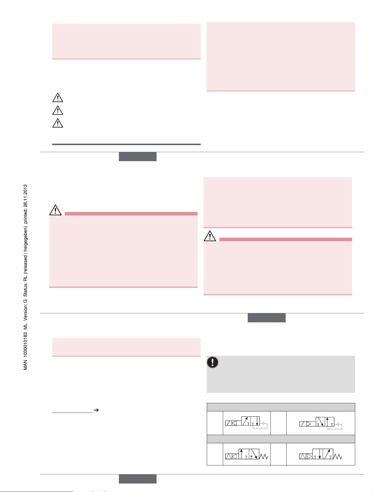
Operating principle 3/2-way valve Type 0340 and 0344:
Standard Version
C
(NC)
A
PR
D
(NO)
B
PR
Impulse Version
C
(NC)
A
P
R
1
2
3
D
(NO)
B
P
R
1
2
3
→ Type 0344: Connect vacuum pump to connection R.
english
Type 0340, 0343, 0344
Page 3
5
Operating principle 3/2-way valve Type 0343:
Standard Version
C
(NC)
A
PR
T
Z
Continuity A → R normally open,
connect vacuum generator to R,
external air to P, auxiliary control air to Z
D
(NO)
B
PR
T
Z
Continuity P → B normally open,
connect vacuum generator to R,
external air to P, auxiliary control air to Z
1)
The externally controlled valve, Type 0343, requires auxiliary control air which
is at least 2 bar above operating pressure
Protection class: IP65 in accordance with DIN EN 60529 /
IEC 60529 with cable plug, e. g. Bürkert
Type 2508
4.2 Application conditions
Ambient temperature: 0 °C ... +55 °C
Medium temperature: 0 °C ... +90 °C
Viscosity (Type 0340): 21 mm
2
/s
Media
Type 0340: neutral media, compressed air, water,
hydraulic oil
Type 0343 / 0344: neutral gas, compressed air, vacuum
Operating duration: Unless otherwise indicated on the type label,
the solenoid system is suitable for continuous
operation
Important information for functional reliability during continuous
operation! If standstill for a long period at least 1-2 operation
per day are recommended.
Service life: High switching frequency and high pressures
reduce the service life
4.3 Conformity
In accordance with the EC Declaration of conformity, the solenoid valve
Type 0340, 0343 and 0344 is compliant with the EC Directives.
4.4 Standards
The applied standards, which verify conformity with the EC Directives,
can be found on the EC Type Examination Certificate and / or the EC
Declaration of Conformity.
english
6
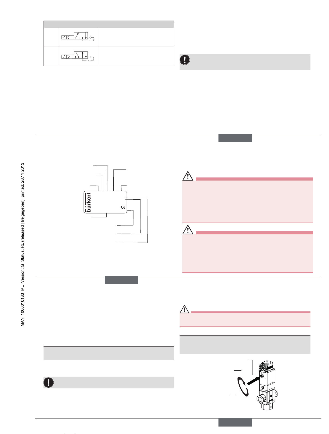
4.5 Type label
Typ e
Operating
principle
Orifice
Seal material
Body material
Id.- Number
Manufacture-Code
Voltage, Frequency, Power
consumption
Connection thread, Operating
pressure
0340 C 12,0 NBR MS
Made in Germany
00041346
W17MG
230V 50 Hz 8W
G1/2 P
N 0,5 - 1 6 bar
5 INSTALLATION
5.1 Safety instructions
Danger!
Risk of injury from high pressure in the equipment!
▶ Before loosening the lines and valves, turn off the pressure and
vent the lines.
Risk of injury due to electrical shock!
▶ Before reaching into the system, switch off the power supply and
secure to prevent reactivation!
▶ Observe applicable accident prevention and safety regulations for
electrical equipment!
Warning!
Risk of injury from improper installation!
▶ Installation may be carried out by authorized technicians only and
with the appropriate tools!
Risk of injury from unintentional activation of the system and an
uncontrolled restart!
▶ Secure system from unintentional activation.
▶ Following installation, ensure a controlled restart.
english
7
5.2 Before installation
Installation position: any, actuator preferably upwards.
Procedure:
→ Check pipelines for dirt and clean.
→ Install a dirt filter before the valve inlet (≤ 500 µm).
5.3 Installation
note!
Caution risk of breakage!
• Do not use the coil as a lifting arm.
→ Hold the device with a open-end wrench on the body and screw
into the pipeline.
Valve body must not be installed under tension.
→ Observe pin assignment according to switching function and
identification.
5.4 Manual emergency actuation
Caution!
Discharge of medium due to loss of the O-rings!
▶ If the O-rings are lost, the valve will leak. Medium may be discharged.
note!
Caution!
• When the manual emergency actuation is locked, the valve can no
longer be actuated electrically.
Manual emergency
actuation
Press
Turn
1
2
english
Type 0340, 0343, 0344
Page 4
8
Danger!
Discharge of medium due to leaking device!
If the O-rings are forgotten or incorrectly inserted during installation
of the pilot valve, the device will be damaged and medium will be
discharged.
▶ Before screwing in the pilot valve, correctly insert O-rings into the
depressions.
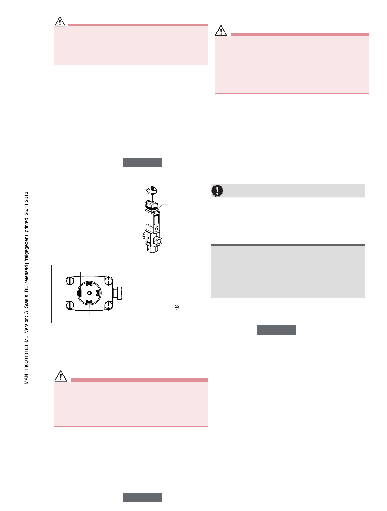
5.5 Electrical connection of the cable plug
Warning!
Risk of injury due to electrical shock!
▶ Before reaching into the system, switch off the power supply and
secure to prevent reactivation!
▶ Observe applicable accident prevention and safety regulations for
electrical equipment!
If the protective conductor contact between the coil and body is
missing, there is danger of electrical shock!
▶ Always connect protective conductor.
▶ Check electrical continuity between coil and body.
Procedure:
→ Tighten cable plug (for permitted types see data sheet), observing
max. torque 1 Nm.
→ Check that seal is fitted correctly.
→ Connect protective conductor and check electrical continuity between
coil and body.
english
9
Authorized cable plug e.g.
Type 2508 or other suitable
cable plug in accordance with
DIN EN 175301-803 Form A
Seal
max. 1 Nm
5.5.1 Electrical connection - Pulse
DC connections:
Terminal 1 = closed +
Terminal 2 = open +
Terminal 3 = GND Terminal 4 = Protective conductor
Protective conductor
connection
24 3
1
The connection terminals in the cable plug are identified with
the numbers 1 to 3 according to the terminals on the valve.
Procedure:
→ Connect the pulse valves (variable code CF 02).
→ For direct current versions connect negative terminal to terminal 3.
note!
Important information:
• Avoid emitting pulses simultaneously to both coil windings.
• Do not switch any other consumers (relays, etc.) at the same time
as the terminals.
• The coil connection, to which voltage is not applied, must be galvanically isolated (open).
• If two or more valves are switched in parallel, ensure that this
requirement is met by using 2-pole or multi-pole switches.
english
10
6 MAINTENANCE, TROUBLESHOOTING
6.1 Safety instructions
Warning!
Risk of injury from improper maintenance!
▶ Maintenance may be carried out by authorized technicians only and
with the appropriate tools!
Risk of injury from unintentional activation of the system and an
uncontrolled restart!
▶ Secure system from unintentional activation.
▶ Following maintenance, ensure a controlled restart.
6.2 Malfunctions
Type 0340: Shipment may have caused the position to occupy a
middle position.
Procedure:
→ Apply pressure to connection P and briefly seal connection A/B,
→ Using your finger, press piston through connection R into the end
position.
If malfunctions occur, check:
→ the device has been installed according to the instructions,
→ the electrical and fluid connections are correct,
→ the device is not damaged and all screws have been tightened,
→ the voltage and pressure have been switched on,
→ the pipelines are clean,
→ corresponding orifice is used in vacuum mode of the pump
capacity (Type 0343 / 0344).
→ Type 0343: operating and control pressure (control pressure must
be at least 2 bar above operating pressure).
Valve does not switch
Possible cause:
• Short-circuit or coil interrupted.
• Medium pressure outside the permitted pressure range.
• Manual emergency actuation locked.
Valve does not close
Possible cause:
• Internal space of the valve is dirty.
• Manual emergency actuation locked.
english
Type 0340, 0343, 0344
Page 5
11
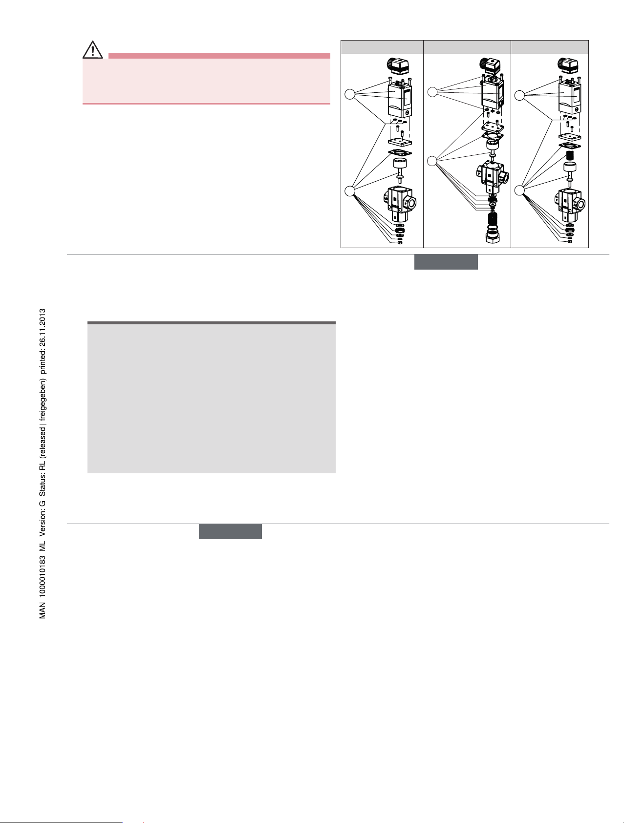
7 SPARE PARTS
Caution!
Risk of injury and/or damage by the use of incorrect parts!
Incorrect accessories and unsuitable spare parts may cause injuries
and damage the device and the surrounding area.
▶ Use only original accessories and original spare parts from Bürkert.
7.1 Ordering spare parts
Order the spare-part sets specifying the positions (Pos. 1: Pilot control
set, Pos. 2: Wearing part set) and the identification number of the
device.
7.2 Overview of spare parts
Type 0340 Type 0343 Type 0344
2
1
1
2
2
1
english
12
8 TRANSPORT, STORAGE, DISPOSAL
note!
Transport damages!
Inadequately protected equipment may be damaged during
transport.
• During transportation protect the device against wet and dirt in
shock-resistant packaging.
•
Avoid exceeding or dropping below the allowable storage
temperature.
Incorrect storage may damage the device.
•
Store the device in a dry and dust-free location!
• Storage temperature: -40 °C ... +80 °C.
Damage to the environment caused by device components
contaminated with media.
• Observe applicable regulations on disposal and the environment.
english
Type 0340, 0343, 0344
Page 6

Bedienungsanleitung
Manuel d‘utilisation
Operating Instructions
Type 0340, 0343, 0344
3/2-way solenoid valve
3/2-Wege-Magnetventil
Électrovanne 3/2 voies
www.burkert.com
International address
www.burkert.com
Manuals and data sheets on the Internet: www.burkert.com
Bedienungsanleitungen und Datenblätter im Internet: www.buerkert.de
Instructions de service et fiches techniques sur Internet : www.buerkert.fr
© Bürker t Werke GmbH , 2013
Operating Instr uctions 1311/03_EU-ML_00893048 / Original DE
Bürkert Fluid Control Systems
Sales Center
Christian-Bürkert-Str. 13-17
D-74653 Ingelfingen
Tel. + 49 (0) 7940 - 10 91 111
Fax + 49 (0) 7940 - 10 91 448
E-mail: info@de.buerkert.com
Page 7

13
1 DIE BEDIENUNGSANLEITUNG
Die Bedienungsanleitung enthält wichtige Informationen.
▶ Bedienungsanleitung sorgfältig lesen und Hinweise zur Sicherheit
beachten.
▶ Bedienungsanleitung muss jedem Benutzer zur Verfügung stehen.
▶ Haftung und Gewährleistung für das Produkt / Gerät entfällt, wenn
die Anweisungen der Bedienungsanleitung nicht beachtet werden.
1.1 Darstellungsmittel
▶ markiert eine Anweisung zur Gefahrenvermeidung.
→ markiert einen Arbeitsschritt, den Sie ausführen müssen.
Warnung vor Verletzungen:
Gefahr!
Unmittelbare Gefahr! Schwere oder tödliche Verletzungen.
WarnunG!
Mögliche Gefahr! Schwere oder tödliche Verletzungen.
Vorsicht!
Gefahr! Leichte oder mittelschwere Verletzungen.
Warnung vor Sachschäden:
hinWeis!
2 BESTIMMUNGSGEMÄSSER
GEBRAUCH
Bei nicht bestimmungsgemäßem Einsatz des Magnetventils Typ
0340, 0343 und 0344 können Gefahren für Personen, Anlagen in
der Umgebung und die Umwelt entstehen.
▶ Das Gerät ist zum Steuern, Absperren und Dosieren von neutralen
Medien konzipiert.
▶ Mit einer sachgemäß angeschlossenen und montierten Gerätesteck-
dose, z. B. Bürkert Typ 2508 erfüllt das Gerät die Schutzart IP65 nach
DIN EN 60529 / IEC 60529.
▶ Für den Einsatz die in den Vertragsdokumenten und der Bedienungs-
anleitung spezifizierten zulässigen Daten, Betriebs- und Einsatzbedingungen beachten.
▶ Voraussetzungen für den sicheren und einwandfreien Betrieb sind
sachgemäßer Transport, sachgemäße Lagerung und Installation sowie
sorgfältige Bedienung und Instandhaltung.
▶ Das Gerät nur bestimmungsgemäß einsetzen.
2.1 Beschränkungen
Beachten Sie bei der Ausfuhr des Geräts bestehende Beschränkungen.
2.2 Begriffsdefinition
Der verwendete Begriff „Gerät“ steht immer für Typ 0340, 0343 und 0344.
deutsch
14
Verletzungsgefahr durch Funktionsausfall bei Ventilen mit
Wechselspannung (AC)!
Festsitzender Kern bewirkt Spulenüberhitzung, die zu Funktionsausfall
führt.
▶ Arbeitsprozess auf einwandfreie Funktion überwachen.
Kurzschlussgefahr/Austritt von Medium durch undichte
Verschraubungen!
▶ Auf einwandfreien Sitz der Dichtungen achten.
▶ V
entil und Anschlussleitungen sorgfältig verschrauben.
Allgemeine Gefahrensituationen.
▶ Keine inneren oder äußeren Veränderungen vornehmen. Anlage/Gerät
vor unbeabsichtigter Betätigung sichern.
▶ I
nstallations- und Instandhaltungsarbeiten dürfen nur von autorisiertem
Fachpersonal mit geeignetem Werkzeug ausgeführt werden.
▶ Nach einer Unterbrechung der elektrischen oder pneumatischen
Versorgung ein definierter oder kontrollierter Wiederanlauf des
Prozesses gewährleisten.
▶ Bei Ausführungen mit ATEX oder UL-Zulassung die Sicherheitshin-
weise des jeweiligen Beiblatts beachten.
3 GRUNDLEGENDE
SICHERHEITSHINWEISE
Diese Sicherheitshinweise berücksichtigen keine Zufälligkeiten und
Ereignisse, die bei Montage, Betrieb und Wartung auftreten können.
Gefahr durch hohen Druck!
▶ Vor dem Lösen von Leitungen und Ventilen den Druck abschalten
und Leitungen entlüften.
Gefahr durch elektrische Spannung!
▶ Vor Eingriffen in das Gerät oder die Anlage Spannung abschalten
und vor Wiedereinschalten sichern.
▶ Die geltenden Unfallverhütungs- und Sicherheitsbestimmungen für
elektrische Geräte beachten.
Verbrennungsgefahr/Brandgefahr bei Dauerbetrieb durch heiße
Geräteoberfläche!
▶ Das Gerät von leicht brennbaren Stoffen und Medien fernhalten und
nicht mit bloßen Händen berühren.
deutsch
15
▶ Gehäuse nicht mechanisch belasten.
▶ Die allgemeinen Regeln der Technik einhalten.
3.1 Gewährleistung
Voraussetzung für die Gewährleistung ist der bestimmungsgemäße Gebrauch des Geräts unter Beachtung der spezifizierten
Einsatzbedingungen.
3.2 Informationen im Internet
Bedienungsanleitungen und Datenblätter zum Typ 0340, 0343 und 0344
finden Sie im Internet unter:
www.buerkert.de
Typ 0340, 0343, 0344
4 TECHNISCHE DATEN
4.1 Betriebsbedingungen
Folgende Werte sind auf dem Typschild angegeben:
• Spannung (Toleranz ± 10 %) / Stromart
• Spulenleistung (Wirkleistung in W - betriebswarm)
• Druckbereich
1)
• Gehäusewerkstoff: Messing (MS)
• Dichtwerkstoff: NBR
Wirkungsweise 3/2-Wege-Ventil Typ 0340 und 0344:
Standard Ausführung
C
(NC)
A
PR
D
(NO)
B
PR
Impuls Ausführung
C
(NC)
A
P
R
1
2
3
D
(NO)
B
P
R
1
2
3
→ Beim Typ 0344: Vakuumpumpe an Anschluss R anschließen.
deutsch
Typ 0340, 0343, 0344
Page 8

16
Wirkungsweise 3/2-Wege-Ventil Typ 0343:
Standard Ausführung
C
(NC)
A
PR
T
Z
Stromlos Durchgang A → R offen,
Vakuumerzeuger an R anschließen,
Außenluft an P, Steuerhilfsluft an Z
D
(NO)
B
PR
T
Z
Stromlos Durchgang P → B offen,
Vakuumerzeuger an R anschließen,
Außenluft an P, Steuerhilfsluft an Z
1)
Das fremdgesteuerte Ventil Typ 0343 benötigt eine Steuerhilfsluft von min-
destens 2 bar über dem Betriebsdruck
Schutzklasse: IP65 nach DIN EN 60529 / IEC 60529
mit Gerätesteckdose, z. B. Bürkert Typ
2508
4.2 Einsatzbedingungen
Umgebungstemperatur: 0 °C ... +55 °C
Mediumstemperatur: 0 °C ... +90 °C
Viskosität (Typ 0340): 21 mm
2
/s
Zulässige Medien
Typ 0340: neutrale Medien, Druckluft, Wasser,
Hydrauliköl
Typ 0343 / 0344: neutrale Gase, Druckluft, Vakuum
Betriebsdauer: Wenn auf dem Typschild nicht anders
angegeben, ist das Magnetsystem für
Dauerbetrieb geeignet
Wichtiger Hinweis für die Funktionssicherheit bei Dauerbetrieb!
Bei langem Stillstand wird eine Betätigung von mindestens 1-2
Schaltungen pro Tag empfohlen.
Lebensdauer: Hohe Schaltfrequenz und hohe Drücke
verringern die Lebensdauer
4.3 Konformität
Das Magnetventil, Typ 0340, 0343 und 0344 ist konform zu den EGRichtlinien entsprechend der EG-Konformitätserklärung.
4.4 Normen
Die angewandten Normen, mit denen die Konformität mit den EG-Richtlinien nachgewiesen wird, sind in der EG-Baumusterprüfbescheinigung
und/oder der EG-Konformitätserklärung nachzulesen.
deutsch
17
4.5 Typschild
Typ
Wirkungsweise
Nennweite
Dichtwerkstoff
Gehäusewerkstoff
Identnummer
Hersteller-Code
Spannung, Frequenz, Leistung
Anschlussart, Betriebsdruck
0340 C 12,0 NBR MS
Made in Germany
00041346
W17MG
230V 50 Hz 8W
G1/2 P
N 0,5 - 1 6 bar
5 MONTAGE
5.1 Sicherheitshinweise
Gefahr!
Verletzungsgefahr durch hohen Druck in der Anlage!
▶ Vor dem Lösen von Leitungen oder Ventilen den Druck abschalten
und Leitungen entlüften.
Verletzungsgefahr durch Stromschlag!
▶ Vor Eingriffen in das Gerät oder die Anlage Spannung abschalten
und vor Wiedereinschalten sichern!
▶ Die geltenden Unfallverhütungs- und Sicherheitsbestimmungen für
elektrische Geräte beachten!
WarnunG!
Verletzungsgefahr bei unsachgemäßer Montage!
▶ Die Montage darf nur autorisiertes Fachpersonal mit geeignetem
Werkzeug durchführen!
Verletzungsgefahr durch ungewolltes Einschalten der Anlage
und unkontrollierten Wiederanlauf!
▶ Anlage vor unbeabsichtigtem Betätigen sichern.
▶ Nach der Montage einen kontrollierten Wiederanlauf gewährleisten.
deutsch
18
5.2 Vor dem Einbau
Einbaulage: beliebig, vorzugsweise Antrieb oben.
Vorgehensweise:
→ Rohrleitungen von eventuellen Verschmutzungen säubern.
→ Vor dem Ventileingang einen Schmutzfilter einbauen (≤ 500 µm).
5.3 Einbau
hinWeis!
Vorsicht Bruchgefahr!
• Spule nicht als Hebelarm benutzen.
→ Das Gerät mit einem Gabelschlüssel am Gehäuse festhalten und in
die Rohrleitung einschrauben.
Ventilgehäuse darf nicht verspannt eingebaut werden.
→ Anschlussbelegung nach Schaltfunktion und Kennzeichnung
beachten.
5.4 Handbetätigung
Vorsicht!
Mediumsaustritt durch Verlust der O-Ringe!
▶ Verlust der O-Ringe führt zur Undichtheit des Ventils. Medium kann
austreten!
hinWeis!
Vorsicht!
• Bei arretierter Handbetätigung kann das Ventil elektrisch nicht mehr
betätigt werden.
Handbetätigung
Drücken
Drehen
1
2
deutsch
Typ 0340, 0343, 0344
Page 9

19
Gefahr!
Mediumsaustritt durch undichtes Gerät!
Werden bei der Montage des Vorsteuerventils die O-Ringe vergessen
oder unkorrekt eingesetzt, führt das zur Beschädigung des Geräts und
Mediumsaustritt.
▶ O-Ringe vor dem Verschrauben korrekt in die Vertiefungen
einsetzen.
5.5 Elektrischer Anschluss der
Gerätesteckdose
WarnunG!
Verletzungsgefahr durch Stromschlag!
▶ Vor Eingriffen in das Gerät oder die Anlage, Spannung abschalten
und vor Wiedereinschalten sichern!
▶ Die geltenden Unfallverhütungs- und Sicherheitsbestimmungen für
elektrische Geräte beachten!
Bei nicht angeschlossenem Schutzleiter besteht die Gefahr des
Stromschlags!
▶ Schutzleiter immer anschließen und elektrischer Durchgang zwi-
schen Spule und Gehäuse prüfen.
Vorgehensweise:
→ Gerätesteckdose (zugelassene Typen siehe Datenblatt) fest-
schrauben, dabei maximales Drehmoment 1 Nm beachten.
→ Korrekten Sitz der Dichtung überprüfen.
→ Schutzleiter anschließen und elektrischer Durchgang zwischen Spule
und Gehäuse prüfen.
deutsch
20
Zugelassene Gerätesteckdose
z. B. Typ 2508 oder andere
geeignete Gerätesteckdose
nach
DIN EN 175301-803 Form A
Dichtung
max. 1 Nm
5.5.1 Elektrischer Anschluss - Impuls
Anschlüsse bei DC:
Klemme 1 = zu +
Klemme 2 = auf +
Klemme 3 = GND Klemme 4 = Schutzleiter
Schutzleiteranschluss
24 3
1
Die Anschlussklemmen in der Gerätesteckdose sind entsprechend
den Klemmen am Ventil mit den Ziffern 1 bis 3 gekennzeichnet.
Vorgehensweise:
→ Impulsventile (variable code CF 02) anschließen.
→ Bei Gleichspannungsausführungen Minuspol an Klemme 3
anschließen.
hinWeis!
Wichtige Hinweise:
• Gleichzeitige Impulsgabe auf beide Spulenwicklungen vermeiden.
• Parallel zu den Klemmen dürfen keine weiteren Verbraucher (Relais
und dergl.) geschaltet werden.
• Der jeweils nicht spannungsbeaufschlagte Spulenanschluss muss
galvanisch getrennt (offen) sein.
• Sollten zwei oder mehr Ventile parallel geschaltet werden, ist durch
Verwendung von 2- oder mehrpoligen Schaltern sicherzustellen,
dass diese Forderung erfüllt ist.
deutsch
21
6 WARTUNG, FEHLERBEHEBUNG
6.1 Sicherheitshinweise
WarnunG!
Verletzungsgefahr bei unsachgemäßen Wartungsarbeiten!
▶ Die Wartung darf nur autorisiertes Fachpersonal mit geeignetem
Werkzeug durchführen!
Verletzungsgefahr durch ungewolltes Einschalten der Anlage
und unkontrollierten Wiederanlauf!
▶ Anlage vor unbeabsichtigtem Betätigen sichern.
▶ Nach der Wartung einen kontrollierten Wiederanlauf gewährleisten.
6.2 Störungen
Typ 0340: Transportbedingt kann der Kolben eine Mittelstellung einge-
nommen haben.
Vorgehensweise:
→ Anschluss P mit Druck beaufschlagen und Anschluss A/B kurz-
zeitig verschließen,
→ Kolben mit dem Finger durch Anschluss R in die Endlage drücken.
Bei Störungen überprüfen ob:
→ das Gerät vorschriftsmäßig installiert ist,
→ der elektrische und fluidische Anschluss ordnungsgemäß ausgeführt ist,
→ das Gerät nicht beschädigt ist und alle Schrauben angezogen sind,
→ Spannung und Druck anliegen,
→ die Rohrleitungen schmutzfrei sind,
→ bei Vakuumbetrieb der Pumpenleistung entsprechende Nennweite
eingesetzt ist (Typ 0343 / 0344).
→ bei Typ 0343: Betriebs- und Steuerdruck anliegen (Steuerdruck
muss mindestens 2 bar über dem Betriebsdruck liegen).
Ventil schaltet nicht
Mögliche Ursache:
• Kurzschluss oder Spulenunterbrechung,
• Mediumsdruck außerhalb das zulässigen Druckbereichs,
• Handbetätigung arretiert.
Ventil schließt nicht
Mögliche Ursache:
• Innenraum des Ventils verschmutzt,
• Handbetätigung arretiert.
deutsch
Typ 0340, 0343, 0344
Page 10

22
7 ERSATZTEILE
Vorsicht!
Verletzungsgefahr, Sachschäden durch falsche Teile!
Falsches Zubehör und ungeeignete Ersatzteile können Verletzungen
und Schäden am Gerät und dessen Umgebung verursachen.
▶ Nur Originalzubehör sowie Originalersatzteile der Firma Bürkert
verwenden.
7.1 Ersatzteile bestellen
Bestellen Sie die Ersatzteilsätze unter Angabe der Positionen
(Pos. 1: Vorsteuerventil, Pos. 2: Verschleißteilsatz) und der Identnummer des Geräts.
7.2 Übersicht Ersatzteile
Typ 0340 Typ 0343 Typ 0344
2
1
1
2
2
1
deutsch
23
8 TRANSPORT, LAGERUNG,
ENTSORGUNG
hinWeis!
Transportschäden!
Unzureichend geschützte Geräte können durch den Transport
beschädigt werden.
• Gerät vor Nässe und Schmutz geschützt in einer stoßfesten Verpackung transportieren.
• Eine Über- bzw. Unterschreitung der zulässigen Lagertemperatur
vermeiden.
Falsche Lagerung kann Schäden am Gerät verursachen.
• Gerät trocken und staubfrei lagern!
• Lagertemperatur: -40 °C ... +80 °C
Umweltschäden durch von Medien kontaminierte Geräteteile.
• Geltende Entsorgungsvorschriften und Umweltbestimmungen
einhalten.
•
Nationale Abfallbeseitigungsvorschriften beachten.
deutsch
Typ 0340, 0343, 0344
Page 11

Bedienungsanleitung
Manuel d‘utilisation
Operating Instructions
Type 0340, 0343, 0344
3/2-way solenoid valve
3/2-Wege-Magnetventil
Électrovanne 3/2 voies
www.burkert.com
International address
www.burkert.com
Manuals and data sheets on the Internet: www.burkert.com
Bedienungsanleitungen und Datenblätter im Internet: www.buerkert.de
Instructions de service et fiches techniques sur Internet : www.buerkert.fr
© Bürker t Werke GmbH , 2013
Operating Instr uctions 1311/03_EU-ML_00893048 / Original DE
Bürkert Fluid Control Systems
Sales Center
Christian-Bürkert-Str. 13-17
D-74653 Ingelfingen
Tel. + 49 (0) 7940 - 10 91 111
Fax + 49 (0) 7940 - 10 91 448
E-mail: info@de.buerkert.com
Page 12

24
1 MANUEL D’UTILISATION
Manuel d’utilisation contiennent des informations importantes.
▶ Lire attentivement ce manuel d’utilisation et respecter les consignes
de sécurité.
▶ Le manuel d’utilisation doit être à disposition de chaque utilisateur.
▶ Nous déclinons toute responsabilité et n’accordons aucune garantie
légale pour le produit / l’appareil en cas de non-respect des instructions
figurant dans ce manuel d’utilisation.
1.1 Symboles
▶ Identifie une instruction visant à éviter un danger.
→ identifie une opération que vous effectuer.
Mise en garde contre les blessures :
Danger !
Danger imminent ! Les blessures graves ou mortelles.
avertissement !
Danger possible ! Les blessures graves ou mortelles.
attention !
Danger ! Les blessures légères ou moyennement graves.
Met en garde contre des dommages matériels :
remarque !
2 UTILISATION CONFORME
L’utilisation non-conforme du type 0340, 0343 et 0344 peut présenter des dangers pour les personnes, les installations avoisinantes et l’environnement.
▶ L’appareil est conçu pour commander, arrêter et doser des fluides
neutres.
▶ Avec une un connecteur adéquat, par ex. le type 2508 de Bürkert,
connectée et montée de manière conforme, l’appareil est conforme au
type de protection IP65 selon DIN EN 60529 / IEC 60529.
▶ Lors de l’utilisation, il convient de respecter les données et conditions
d’utilisation et d’exploitation admissibles spécifiées dans les instructions de service et dans les documents contractuels.
▶ Les conditions pour l’utilisation sûre et parfaite sont un transport,
un stockage et une installation dans les règles ainsi qu’une parfaite
utilisation et maintenance.
▶ Veillez à ce que l’utilisation de l’appareil soit toujours conforme.
2.1 Limitations
Lors de l’exportation du système/de l’appareil, veuillez respecter les limitations éventuelles existantes.
2.2 Définition du terme appareil
Le terme « appareil » utilisé dans ces instructions désigne toujours la
Électrovanne type 0340, 0343 et 0344.
français
25
Risque de blessure dû à une panne pour les vannes avec
tension alternative (AC).
Un noyau bloqué provoque la surchauffe de la bobine et donc une
panne.
▶ Surveiller le bon fonctionnement du processus de travail.
Risque de court-circuit / de sortie du fluide en présence de vissages non étanches.
▶ Veiller à l’installation correcte des joints.
▶ Visser soigneusement la vanne et les raccords de la tuyauterie.
Pour prévenir les blessures, respectez ce qui suit :
▶ N’apportez pas de modifications à l’extérieur du corps de l’appareil.
L’installation ne peut pas être actionnée par inadvertance.
▶ Les
travaux d’installation et de maintenance doivent être effectués
uniquement par des techniciens qualifiés et habilités disposant de
l’outillage approprié.
▶ Après une interruption de l’alimentation électrique ou pneumatique,
un redémarrage défini ou contrôlé du processus doit être garanti.
▶ Pour les versions avec homologation ATEX ou UL, il convient de
respecter les consignes de sécurité figurant dans la fiche annexe
correspondante.
3 CONSIGNES DE SÉCURITÉ
FONDAMENTALES
Ces consignes de sécurité ne tiennent pas compte des hasards et des événements pouvant survenir lors du montage, de l’exploitation et de l’entretien.
Danger dû à la haute pression.
▶ Avant de desserrer les conduites et les vannes, coupez la pression
et purgez les conduites.
Danger présenté par la tension électrique.
▶ Avant d’intervenir dans le système, coupez la tension et empêchez
toute remise sous tension par inadvertance.
▶ Veuillez respecter les réglementations en vigueur pour les appareils
électriques en matière de prévention des accidents ainsi qu’en
matière de sécurité.
Risque de brûlures/d’incendie en fonctionnement continu dû à
des surfaces d’appareils brûlantes.
▶ Tenez les substances et les fluides facilement inflammables à l’écart
de l’appareil et ne touchez pas ce dernier à mains nues.
français
26
▶ Ne soumettez pas le corps à des contraintes mécaniques.
▶ Les règles générales de la technique sont d’application pour plani-
fier l’utilisation et utiliser l’appareil.
3.1 Garantie légale
La condition pour bénéficier de la garantie légale est l’utilisation conforme
du type 0340, 0343 et 0344 dans le respect des conditions d’utilisation
spécifiées.
3.2 Informations sur Internet
Vous trouverez sur Internet les instructions de service et fiches techniques
relatives au type 0340, 0343 et 0344:
www.buerkert.fr
Type 0340, 0343, 0344
4
CARACTÉRISTIQUES TECHNIQUES
4.1 Conditions d’exploitation
Les valeurs sont indiquées sur la plaque signalétique :
• Tension (Tolérance ± 10 %) / Type de courant
• Puissance de bobine (puissance active en W - à l’état chaud)
• Plaque de pression
1)
• Matériau du corps : Laiton (MS)
• Matériau du joint : NBR
Fonction vanne 3/2 voies Type 0340 et 0344 :
Version Standard
C
(NC)
A
PR
D
(NO)
B
PR
Version Impulsion
C
(NC)
A
P
R
1
2
3
D
(NO)
B
P
R
1
2
3
→ Type 0344 : Raccorder la pompe à vide au raccord R.
français
Type 0340, 0343, 0344
Page 13

27
Fonction vanne 3/2 voies Type 0343 :
Version Standard
C
(NC)
A
PR
T
Z
Passage A → R normalement ouvert,
raccorder le générateur de vide sur R,
l’air extérieur sur P, l’air auxiliaire de
commande sur Z
D
(NO)
B
PR
T
Z
Passage P → B normalement ouvert,
raccorder le générateur de vide sur R,
l’air extérieur sur P, l’air auxiliaire de
commande sur Z
1)
La vanne à commande externe de type 0343 nécessite de l’air auxiliaire de commande dont la pression est au minimum 2 bar au-dessus de la pression de service
Classe de protection : IP65 selon DIN EN 60529 / IEC 60529
avec une connecteur, par le type 2508
de Bürkert
4.2 Conditions d’utilisation
Température ambiante : 0 °C ... +55 °C
Température du fluide : 0 °C ... +90 °C
Viscosité (Type 0340) : 21 mm
2
/s
Fluide
Type 0340 : Fluides neutres, air comprimé, eau, huile
hydraulique
Type 0343 / 0344 : Gaz neutres, air comprimé, vide
Durée de fonctionnement : Si aucune information contraire ne figure
sur la plaque signalétique, le système
magnétique est adapté à un fonction-
nement continu
Remarque importante pour la sécurité de fonctionnement lors
d’un fonctionnement continu ! Dans le cas d’un fonctionnement
de longue durée, il est recommandé de procéder à 1 - 2 commutations minimum par jour.
Durée de vie : Une fréquence élevée de commutation ainsi que des
pressions élevées réduisent la durée de vie
4.3 Conformité
L‘électrovanne type 0340, 0343 et 0344 est conforme aux directives
CE sur la base de la déclaration de conformité CE.
français
28
4.4 Normes
Les normes appliquées justifiant la conformité aux directives CE peuvent
être consultées dans le certificat d’essai de modelé type CE et / ou la
déclaration de Conformité CE.
4.5 Plaque signalétique
Typ e
Fonction
Diamètre
nominal
Matériau du joint
Matériau du corps
N° d’identification
Code fabricant
Tension, Fréquence,
Puissance
Raccordement, Pression
nominale
0340 C 12,0 NBR MS
Made in Germany
00041346
W17MG
230V 50 Hz 8W
G1/2 P
N 0,5 - 1 6 bar
5 INSTALLATION
5.1 Consignes de sécurité
Danger !
Risque de blessures dû à la présence de haute pression dans l'installation.
▶ Avant de desserrer les conduites et les vannes, coupez la pression
et purgez les conduites.
Risque de choc électrique.
▶ Avant d'intervenir dans le système, coupez la tension et empêchez
toute remise sous tension par inadvertance !
▶ Veuillez respecter les réglementations en vigueur pour les appareils électriques
en matière de prévention des accidents ainsi qu’en matière de sécurité.
avertissement !
Risque de blessures dû à un montage non conforme.
▶ Le montage doit être effectué uniquement par un personnel qualifié et
habilité disposant de l’outillage approprié.
Risque de blessures dû à la mise en marche involontaire de l'installation
et le redémarrage non contrôlé.
▶ Empêchez tout actionnement involontaire de l'installation.
▶ Garantissez un redémarrage contrôlé après le montage.
français
29
5.2 Avant le montage
Position de montage : au choix, de préférence avec l’actionneur vers le
haut.
Procédure :
→ Contrôler les tuyauteries pour encrassements et les nettoyer.
→ Installer un filtre à saleté devant l’entrée de vanne (≤ 500 µm).
5.3 Installation
remarque !
Attention risque de rupture.
• La bobine ne doit pas être utilisée comme levier.
→ Maintenez l’appareil sur le corps à l’aide d’un outil approprié (clé à
fourche) et vissez-le dans la tuyauterie.
Le corps de vanne ne doit pas être monté sous tension.
→ Respecter l’affectation du raccordement conformément à la
fonction de commutation et à l’identification.
5.4 Actionnement manuel d’urgence
attention !
Sortie de fluide due à la perte des joints toriques.
▶ La perte des joints toriques rend la vanne non étanche. Risque de
sortie de fluide !
remarque !
Attention.
• Lorsque l’actionnement manuel d’urgence est bloqué, l’actionnement
électrique de la vanne n’est plus possible.
Actionnement
manuel d’urgence
Appuyer
Tourner
1
2
français
Type 0340, 0343, 0344
Page 14

30
Danger !
Sortie de fluide due à la non-étanchéité de l’appareil.
L’oubli ou le mauvais positionnement des joints toriques lors du
montage de la vanne pilote endommage l’appareil et entraîne la sortie
de fluide.
▶ Positionnez correctement les joints toriques dans les creux avant de
visser.
5.5 Raccordement électrique du connecteur
avertissement !
Risque de choc électrique.
▶ Avant d’intervenir dans le système, coupez la tension et empêchez
toute remise sous tension par inadvertance.
▶ Veuillez respecter les réglementations en vigueur pour les appareils
électriques en matière de prévention des accidents ainsi qu’en matière
de sécurité.
Il y a risque de choc électrique en l’absence d’un contact du conducteur
de protection entre la bobine et le corps.
▶ Raccordez toujours le conducteur de protection et contrôlez le
passage du courant entre la bobine et le corps.
Procédure :
→ Visser le connecteur (types admissibles, voir fiche technique) en
respectant le couple max. de 1 Nm.
→ Vérifier le bon positionnement du joint.
→ Raccorder le conducteur de protection et vérifier le passage électrique
entre la bobine et le corps.
français
31
Connecteur autorisé par ex.
type 2508 ou autres connecteurs
adéquates selon
DIN EN 175301-803 forme A
Joint
max. 1 Nm
5.5.1 Raccordement électrique - impulsion
Raccords pour DC :
Borne 1 = fermé +
Borne 2 = ouvert +
Borne 3 = GND Borne 4 = Conducteur de protection
Raccord du
conducteur de protection
24 3
1
Les bornes de raccordement dans la connecteur sont identifiées
par les chiffres 1 à 3 conformément aux bornes de la vanne.
Procédure :
→ Raccorder les vannes à impulsions (code variable CF 02).
→ Pour les versions à tension continue, raccorder le pôle négatif à la
borne 3.
remarque !
Remarques importantes :
▶ Éviter de donner des impulsions simultanément sur les deux enrou-
lements de bobine.
▶ Aucun autre consommateur ne doit être activé en parallèle avec les
bornes (relais et semblables).
▶ Le raccord de bobine auquel aucune tension n’est appliquée doit
être isolé électriquement (ouvert).
▶ En cas de montage en parallèle de deux ou plusieurs vannes, il
convient de garantir le respect de cette exigence par l’utilisation
d’interrupteurs bipolaires ou multipolaires.
français
32
6 MAINTENANCE, DÉPANNAGE
6.1 Consignes de sécurité
avertissement !
Risque de blessures dû à des travaux de maintenance non
conformes.
▶ La maintenance doit être effectué uniquement par un personnel
qualifié et habilité disposant de l’outillage approprié.
Risque de blessures dû à la mise en marche involontaire de l’installation et le redémarrage non contrôlé.
▶ Empêchez tout actionnement involontaire de l’installation.
▶ Garantissez un redémarrage contrôlé après la maintenance.
6.2 Pannes
Type 0340: Suite au transport, le piston peut se trouver en position
centrale.
Procédure :
→ Appliquer la pression au raccord P et fermer brièvement le raccord
A/B,
→ Avec le doigt, appuyer le piston dans le raccord R en position finale.
En présence de pannes, vérifiez :
→ si l’appareil est installé dans les règles,
→ si le raccord électrique et fluide est correct,
→ si l’appareil n’est pas endommagé et toutes les vis sont bien serrées,
→ si la tension et la pression sont disponibles,
→ si les tuyauteries sont propres,
→ le diamètre nominal correspondant au débit de la pompe en mode
sous vide a été utilisé (Type 0343 / 0344),
→ Type 0343: Vérifier les pressions de service et de commande
(la pression de commande doit être supérieure à la pression de
service d’au moins 2 bar).
La vanne ne s’enclenche pas
Cause possible :
• Court-circuit ou coupure de la bobine.
• Pression du fluide hors de la plage de pression autorisée.
• Actionnement manuel d’urgence bloqué.
La vanne ne se ferme pas
Cause possible :
• Intérieur de la vanne encrassé.
• Actionnement manuel d’urgence bloqué.
français
Type 0340, 0343, 0344
Page 15

33
7 PIÈCES DE RECHANGE
PruDence !
Risque de blessures, de dommages matériels dus à de mauvaises pièces.
De mauvais accessoires ou des pièces de rechange inadaptées
peuvent provoquer des blessures et endommager l’appareil ou son
environnement.
▶ Utilisez uniquement des accessoires ainsi que des pièces de
rechange d’origine de la société Bürkert.
7.1 Commander des pièces de rechange
Commandez les jeux de pièces de rechange avec mention des postes
(pos. 1 : jeu pilote, pos. 2 : jeu de pièces d’usure) et le numéro d’identification de l’appareil.
7.2 Vue d’ensemble des pièces de rechange
Type 0340 Type 0343 Type 0344
2
1
1
2
2
1
français
34
8 TRANSPORT, STOCKAGE,
ÉLIMINATION
remarque !
Dommages dus au transport.
Les appareils insuffisamment protégés peuvent être endommagés
pendant le transport.
• Transportez l’appareil à l’abri de l’humidité et des impuretés et dans
un emballage résistant aux chocs.
•
Évitez le dépassement vers le haut ou le bas de la température de
stockage admissible.
Un mauvais stockage peut endommager l’appareil.
•
Stockez l’appareil au sec et à l’abri des poussières !
•
Température de stockage :
-40 °C ... +80 °C.
Dommages à l’environnement causés par des pièces d’appareil
contaminées par des fluides.
•
Respectez les prescriptions en matière d’élimination des déchets et
de protection de l’environnement en vigueur.
français
Type 0340, 0343, 0344
 Loading...