

Page 1
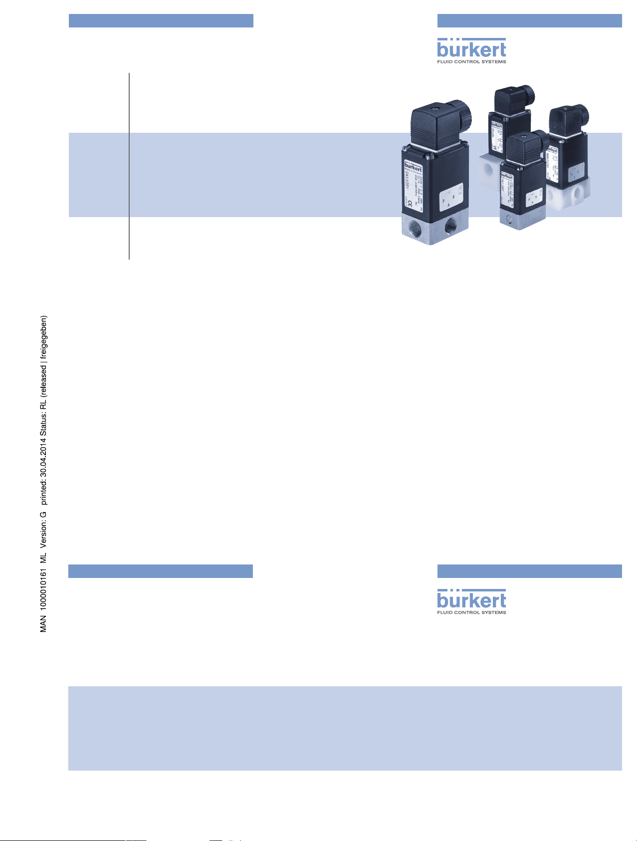
Type 0121, 0330, 0331
(0124, 0125, 0332, 0333)
2/2- and 3/2-Way Solenoid Valve
2/2- und 3/2-Wege-Magnetventil
Électrovanne à 2/2 et 3/2 voies
Bedienungsanleitung
Manuel d‘utilisation
Operating Instructions
www.burkert.com
International address
www.burkert.com
Manuals and data sheets on the Internet: www.burkert.com
Bedienungsanleitungen und Datenblätter im Internet: www.buerkert.de
Instructions de service et fiches techniques sur Internet : www.buerkert.fr
© Bürker t Werke GmbH , 2014
Operating Instr uctions 1402/04_EU-ML_00893047 / Original DE
Bürkert Fluid Control Systems
Sales Center
Christian-Bürkert-Str. 13-17
D-74653 Ingelfingen
Tel. + 49 (0) 7940 - 10 91 111
Fax + 49 (0) 7940 - 10 91 448
E-mail: info@de.buerkert.com
Page 2
2
1 THE OPERATING INSTRUCTIONS
The operating instructions contain important information.
▶ Read the instructions carefully and follow the safety instructions.
▶ Keep the instructions in a location where they are available to every
user.
The liability and warranty for the device are void if the operating
instructions are not followed.
1.1 Symbols
▶ Designates instructions for risk prevention.
→ Designates a procedure which you must carry out.
DANGER!
Immediate danger! Serious or fatal injuries.
WARNING!
Possible danger! Serious or fatal injuries.
CAUTION!
Danger! Moderate or minor injuries.
Table of Contents
1 The operating instructions .................................................................................................. 2
2 Authorized use ..............................................................................................................................3
3 Basic safety instructions.......................................................................................................4
4 System description ....................................................................................................................5
5 Technical data................................................................................................................................6
6 Assembly ...........................................................................................................................................8
7 Electrical connection ............................................................................................................10
8 Disassembly .................................................................................................................................12
9 Maintenance, troubleshooting .......................................................................................12
10 Transportation, storage, disposal ................................................................................13
english
3
2 AUTHORIZED USE
The device is designed to control, shut off and meter neutral
and aggressive media up to a viscosity of 37 mm²/s.
▶ Use according to the authorized data, operating conditions and
conditions of use specified in the contract documents and operating instructions.
▶ Provided the cable plug is connected and installed correctly, e.g.
Bürkert Type 2508, the device satisfies degree of protection IP65
in accordance with DIN EN 60529 / IEC 60529.
Only operate the device
▶ when in perfect condition and always ensure proper storage, trans-
portation, installation and operation.
▶ Use the device only as intended.
2.1 Restrictions
If exporting the device, observe any existing restrictions.
NOTE!
Warns of damage to property.
Important tips and recommendations.
Refers to information in these operating instructions or in other
documentation.
1.2 Definitions of terms
In these instructions, the term "device" always refers to the Type 0121,
0330, 0331, (0124, 0125, 0332, 0333).
english
4
3 BASIC SAFETY INSTRUCTIONS
These safety instructions do not make allowance for any contingencies
and events which may arise during assembly, operation and maintenance.
Risk of injury from high pressure in the system/device.
▶ Before working on the system or device, switch off the pressure
and vent/drain lines.
Risk of injury due to electrical shock.
▶ Before working on the system or device, switch off the power supply
and secure to prevent reactivation.
▶ Observe applicable accident prevention and safety regulations for
electrical equipment.
Risk of burns/risk of fire if used for a prolonged switch-on time
through hot device surface.
▶ Keep device away from highly flammable substances and media and
do not touch with bare hands.
Risk of injury due to malfunction of valves with alternating
voltage (AC).
Sticking core causes coil to overheat, resulting in a malfunction.
▶ Monitor process to ensure function is in perfect working order.
Risk of short-circuit/escape of media through leaking screw
joints.
▶ Ensure seals are seated correctly.
▶ Carefully screw valve and pipelines together.
english
Type 0121 / 0330 / 0331
Page 3
5
General hazardous situations.
To prevent injuries:
▶ In a potentially explosive area, the device may be used only in accor-
dance with the specification on the type label. For the use, observe
the supplementary instructions manual enclosed with the device with
safety instructions for the explosion-risk area.
▶ The enclosed UL instructions must be followed in the UL area.
▶ Do not carry out any external or internal modifications and do not
subject the device to mechanical loads (e.g. by placing objects on
it or standing on it).
▶ Secure the device against unintentional activation.
▶ Only trained technicians may perform installation and maintenance
work.
▶ The valves must be installed in accordance with the regulations
applicable in the country.
▶ After an interruption in the power supply, ensure that the process is
restarted in a controlled manner.
▶ Observe the general rules of technology.
4 SYSTEM DESCRIPTION
4.1 General description
The pivoted armature valves are direct acting 2/2 or 3/2-way solenoid
valves in a wide variety of circuit functions and models. Solenoid system
and media chamber are separated from one another by a separating
diaphragm system. The valves are fast acting and have a long service life.
Type 0121 2/2 or 3/2-way solenoid valve, socket valve body
Type 0330 2/2 or 3/2-way solenoid valve, socket valve body
Type 0331 2/2 or 3/2-way solenoid valve, flange valve body
Type 0332 Bistable 2/2 or 3/2-way solenoid valve
with 2 coil windings, socket valve body
Type 0333 Bistable 2/2 or 3/2-way solenoid valve
with 2 coil windings, flange valve body
Type 0124 2/2 or 3/2-way solenoid valve, socket valve body
Type 0125 2/2 or 3/2-way solenoid valve, flange valve body
english
6
5 TECHNICAL DATA
The following values are indicated on the type label:
• Voltage (tolerance ±10 %) / current type
• Coil power consumption (active power in W - at operating
temperature)
•
Pressure range
• Body material (MS=brass, VA=stainless steel, PV=PVC,
TE=PTFE, PP=polypropylene, PD=PVDF)
• Sealing material
(F=FKM, A=EPDM, B=NBR, C=FFKM)
5.1 Conformity
The Types 0121, 0330, 0331, (0124, 0125, 0332, 0333) are compliant
with the EC Directives according to the EC Declaration of Conformity.
5.2 Standards
The applied standards, which are used to demonstrate compliance with
the EC Directives, are listed in the EC type test certificate and/or the EC
Declaration of Conformity.
5.3 Operating conditions
Ambient temperature
Type 0121 max. +50°C
Other types max. +55°C
Duty cycle
for body material
Brass or stainless steel long-term operation, duty cycle 100%
Plastic
max. permissible duty cycle
see data sheet
Important information for functional reliability.
If switched off for a long period, 1-2 switching actions are recommended prior to restart.
Service life
High switching frequency and high pressures reduce the service life.
Degree of protection IP65 in accordance with DIN EN 60529
/ IEC 60529 with correctly connected
and installed cable plug, e.g. Bürkert
Type 2508
english
7
5.4 Mechanical data
Dimensions see data sheet
Coil material
epoxide
Connections
G 1/4
(NPT 1/4, G 1/8, G 3/8, Rc 1/4 on request)
5.5 Fluidic data
Media aggressive, neutral, gaseous and liquid media,
which do not attack body and sealing materials.
(see resistance table at www.buerkert.de).
Medium temperature for sealing material
FKM 0 °C – +90 °C
EPDM -30 °C – + 90 °C
NBR 0 °C – + 80 °C
FFKM +5 °C – +90 °C
Circuit functions
A
(NC)
2 (A)
1 (P)
2/2-way valve,
closed in rest position
B
(NO)
2 (A)
1 (P)
2/2-way valve,
open in rest position
C
(NC)
2(A)
1(P) 3(R)
3/2-way valve; closed in rest position,
output A unloaded
D
(NO)
4(B)
1(P) 3(R)
3/2-way valve, in rest position, output B
pressurized
E
2(A)
1(P) 3(R)
3/2-way mixing valve; in rest position,
pressure connection P2 connected to
output A, P1 closed
F
2(A) 4(B)
1(P)
3/2-way distribution valve,
in rest position, pressure connection P
connected to output B
T
2(A)
1(P) 3(R)
3/2-way all purpose valve
english
Type 0121 / 0330 / 0331
Page 4

8
5.6 Electrical data
Connections DIN EN 175301-803 (DIN 43 650), shape A for
cable plug Type 2508 or 2509
5.7 Type label
Made in Germany
00450000
W14UN
CE
0330 C 2.0 FKM MS
G1/4 0-6 bar
24V DC 8W
Identification number
Voltage, frequency, output
Port connection, nominal pressure
Type
Circuit function
Orifice
Sealing material
Body material
Fig. 1: Description of the type label (example)
6 ASSEMBLY
DANGER!
Risk of injury from high pressure in the system/device.
▶ Before working on the system or device, switch off the pressure
and vent/drain lines.
Risk of injury due to electrical shock.
▶ Before working on the system or device, switch off the power sup-
ply and secure to prevent reactivation.
▶ Observe applicable accident prevention and safety regulations for
electrical equipment.
WARNING!
Risk of injury from improper assembly.
▶ The assembly may be carried out only by trained technicians and
with the appropriate tools.
▶ Secure system against unintentional activation.
▶ Following assembly, ensure a controlled restart.
english
9
6.1 Before installation
Installation position:
The installation position is optional. Preferably: Actuator at the top.
→ Prior to installation check pipelines for dirt and clean if necessary.
Dirt filter: To ensure that the solenoid valve functions reliably, a dirt filter (≤ 500 µm) must be
installed in front of the valve input.
6.2 Installation
→ Observe flow direction:
Functioning of the device is only ensured if the circuit function is
maintained.
Devices in socket model
→ Use PTFE tape as sealing material.
→ Determine the maximum screw-in depth of the connecting threads
as this does not comply with any standard.
NOTE!
Caution risk of breakage.
▶ Do not use the coil as a lifting arm.
→ Hold the device with a suitable tool (open-end wrench) on the
body; screw into the pipeline.
Attaching the device:
→ Via bore holes M4x8 (made from brass or stainless steel) or self-
tapping screws 3.9 DIN 7970 (made from plastic, max. screw-in
depth 10 mm) on the bottom side of the body at drill pattern
38x24.
Devices in flange model
Attaching the device:
→ Via supplied screws on basic devices or manifold.
→ Tighten fastening screws on the coil to a maximum torque of 2 Nm.
english
10
6.3 Manual control
NOTE!
▶ When the manual control is locked, the valve cannot be actuated
electrically.
1
2
Press
Turn
Manual control
Fig. 2: Manual control
7 ELECTRICAL CONNECTION
DANGER!
Risk of injury due to electrical shock.
▶ Before working on the system or device, switch off the power sup-
ply and secure to prevent reactivation.
▶ Observe
applicable accident prevention and safety regulations for
electrical equipment.
If the protective conductor is not connected, there is a risk of
electric shock.
▶ Always
connect protective conductor and check electrical continuity
between coil and housing.
Approved cable plug, e.g. Type
2508 or other suitable cable plug
in accordance with
DIN EN 175301-803 shape A
max. 1 Nm
Seal
Fig. 3: Connecting the cable plug to the power supply
Note the voltage and current type as specified on the type label.
english
Type 0121 / 0330 / 0331
Page 5
11
7.1 Standard model
→ Connect L1/+ and N/– to terminals 1 and 2, independent of the
polarity.
→ Connect protective conductor.
→ Attach seal and check for correct fit.
→ Tighten cable plug (Type 2508 or 2509 in accordance with DIN EN
175301-803 (DIN 43 650), shape A, for order numbers see data
sheet); while doing so, observe the maximum torque of 1 Nm.
→ Check electrical continuity between coil and body (protective con-
ductor function).
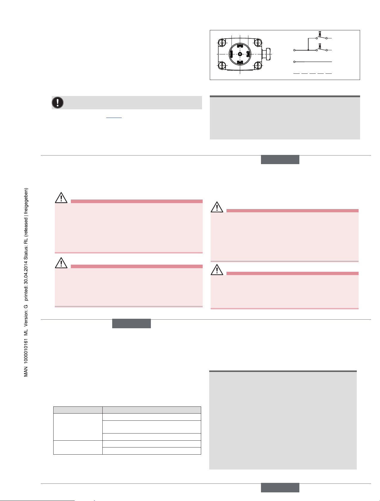
7.2 Pulse model (CF 02)
In accordance with the terminals on the valves, the connection
terminals in the cable plug are marked with the numbers 1 to 3.
→ Connect as shown in “Fig. 4”. Pulse on terminal 1 closes the valve;
pulse on terminal 2 opens the valve.
→ Attach seal and check for correct fit.
→ Tighten cable plug (Type 2508 or 2509 in accordance with DIN EN
175301-803 (DIN 43 650), shape A, for order numbers see data
sheet); while doing so, observe the maximum torque of 1 Nm.
→ Check electrical continuity between coil and body (protective con-
ductor function).
24 3
1
Terminal 1
(=) ∼
(+) L1
(–) N
PE
Terminal 2
Terminal 3
Protective
conductor
Fig. 4: Electrical connection - pulse model (CF 02)
NOTE!
▶ Prevent simultaneous pulsing on both coil windings.
▶ Parallel to the terminals, no other consumers (relay, etc.) may be
connected.
▶ The respective coil connection that does not carry current must be
galvanically isolated (open).
▶ In case two or more valves are connected in parallel, the use of two-
pole or multi-pole switches must ensure that this requirement is met.
english
12
8 DISASSEMBLY
DANGER!
Risk of injury from high pressure in the system/device.
▶ Before working on the system or device, switch off the pressure
and vent/drain lines.
Risk of injury due to electrical shock.
▶ Before working on the system or device, switch off the power
supply and secure to prevent reactivation.
▶ Observe applicable accident prevention and safety regulations
for electrical equipment.
WARNING!
Risk of injury from improper disassembly.
▶ Disassembly may be carried out only by trained technicians and
with the appropriate tools.
Risk of injury from hazardous media.
▶ Before loosening lines or valves, flush out hazardous media,
depressurize and drain the lines.
9 MAINTENANCE, TROUBLESHOOTING
9.1 Safety instructions
DANGER!
Risk of injury from high pressure in the system.
▶ Turn off the pressure and vent the lines before loosening lines or
valves.
Risk of injury due to electrical shock.
▶ Before working on the system or device, switch off the power
supply and secure to prevent reactivation.
▶ Observe applicable accident prevention and safety regulations
for electrical equipment.
WARNING!
Risk of injury from improper maintenance work.
▶ Maintenance may be carried out only by trained technicians and
with the appropriate tools.
▶ Secure system against unintentional activation.
▶ Following maintenance, ensure a controlled restart.
english
13
9.2 Malfunctions
If malfunctions occur, check whether:
→ the device has been installed according to the instructions,
→ the electrical and fluid connections are correct,
→ the device is not damaged,
→ all screws have been tightened,
→ the voltage and pressure have been switched on,
→ the pipelines are clean.
Malfunction Possible cause
Valve does not
switch
Short circuit or coil interrupted
Medium pressure outside the permitted
pressure range
Manual control locked
Valve does not close Inner compartment of the valve is dirty
Manual control locked
9.2.1 Repairs
Repairs may only be carried out by the manufacturer. Operating data
may change if spare parts are replaced by the user.
10 TRANSPORTATION, STORAGE,
DISPOSAL
NOTE!
Transport damage.
Inadequately protected devices may be damaged during
transportation.
▶ Protect the device against moisture and dirt in shock-resistant
packaging during transportation.
▶ Prevent the temperature from exceeding or dropping below the
permitted storage temperature.
Incorrect storage may damage the device.
▶ Store the device in a dry and dust-free location.
▶ Storage temperature -40
– +80°C.
Damage to the environment caused by parts contaminated
with media.
▶ Dispose
of the device and packaging in an environmentally friendly
manner.
▶ Observe applicable disposal and environmental regulations.
english
Type 0121 / 0330 / 0331
Page 6

Type 0121, 0330, 0331
(0124, 0125, 0332, 0333)
2/2- and 3/2-Way Solenoid Valve
2/2- und 3/2-Wege-Magnetventil
Électrovanne à 2/2 et 3/2 voies
Bedienungsanleitung
Manuel d‘utilisation
Operating Instructions
www.burkert.com
International address
www.burkert.com
Manuals and data sheets on the Internet: www.burkert.com
Bedienungsanleitungen und Datenblätter im Internet: www.buerkert.de
Instructions de service et fiches techniques sur Internet : www.buerkert.fr
© Bürker t Werke GmbH , 2014
Operating Instr uctions 1402/04_EU-ML_00893047 / Original DE
Bürkert Fluid Control Systems
Sales Center
Christian-Bürkert-Str. 13-17
D-74653 Ingelfingen
Tel. + 49 (0) 7940 - 10 91 111
Fax + 49 (0) 7940 - 10 91 448
E-mail: info@de.buerkert.com
Page 7

14
1 DIE BEDIENUNGSANLEITUNG
Die Bedienungsanleitung enthält wichtige Informationen.
▶ Anleitung sorgfältig lesen und die Hinweise zur Sicherheit beachten.
▶ Anleitung so aufbewahren, dass sie jedem Benutzer zur Verfügung
steht.
Die Haftung und Gewährleistung für das Gerät entfällt, wenn die
Anweisungen der Bedienungsanleitung nicht beachtet werden.
1.1 Darstellungsmittel
▶ markiert eine Anweisung zur Gefahrenvermeidung.
→ markiert einen Arbeitsschritt den Sie ausführen müssen.
GEFAHR!
Unmittelbare Gefahr! Schwere oder tödlichen Verletzungen.
WARNUNG!
Mögliche Gefahr! Schwere oder tödlichen Verletzungen.
VORSICHT!
Gefahr! Mittelschwere oder leichten Verletzungen.
Inhaltsverzeichnis
1 Die Bedienungsanleitung .................................................................................................14
2 Bestimmungsgemäße Verwendung .........................................................................15
3 Grundlegende Sicherheitshinweise .........................................................................16
4 Systembeschreibung ............................................................................................................17
5 Technische Daten....................................................................................................................18
6 Montage ...................................................................................................................................................20
7 Elektrischer Anschluss........................................................................................................22
8 Demontage ...................................................................................................................................24
9 Wartung, Fehlerbehebung ................................................................................................24
10 Transport, Lagerung, Entsorgung ...............................................................................25
deutsch
15
2 BESTIMMUNGSGEMÄSSE
VERWENDUNG
Das Gerät ist zum Steuern, Absperren und Dosieren von neutralen und aggressiven Medien bis zu einer Viskosität von 37
mm²/s konzipiert.
▶ Für den Einsatz die in den Vertragsdokumenten und der Bedienungs-
anleitung spezifizierten zulässigen Daten, Betriebs- und Einsatzbe-
dingungen beachten.
▶ Mit einer sachgemäß angeschlossenen und montierten Gerätesteck-
dose, z. B. Bürkert Typ 2508 erfüllt das Gerät die Schutzart IP65 nach
DIN EN 60529 / IEC 60529.
Das Gerät
▶ nur in einwandfreiem Zustand betreiben und auf sachgerechte Lage-
rung, Transport, Installation und Bedienung achten.
▶ nur bestimmungsgemäß verwenden.
2.1 Beschränkungen
Bei der Ausfuhr des Geräts gegebenenfalls bestehende Beschränkungen
beachten.
HINWEIS!
Warnt vor Sachschäden.
Wichtige Tipps und Empfehlungen.
verweist auf Informationen in dieser Bedienungsanleitung oder
in anderen Dokumentationen.
1.2 Begriffsdefinition
Der in dieser Anleitung verwendete Begriff „Gerät“ steht immer für Typ
0121, 0330, 0331, (0124, 0125, 0332, 0333).
deutsch
16
3 GRUNDLEGENDE
SICHERHEITSHINWEISE
Diese Sicherheitshinweise berücksichtigen keine Zufälligkeiten und
Ereignisse, die bei Montage, Betrieb und Wartung auftreten können.
Verletzungsgefahr durch hohen Druck in Anlage/Gerät.
▶ Vor Arbeiten an Anlage oder Gerät, den Druck abschalten und
Leitungen entlüften/entleeren.
Verletzungsgefahr durch Stromschlag.
▶ Vor Arbeiten an Anlage oder Gerät, die Spannung abschalten und
vor Wiedereinschalten sichern.
▶ Die geltenden Unfallverhütungs- und Sicherheitsbestimmungen für
elektrische Geräte beachten.
Verbrennungsgefahr/Brandgefahr bei längerer Einschaltzeit
durch heiße Geräteoberfläche.
▶ Gerät von leicht brennbaren Stoffen und Medien fernhalten und nicht
mit bloßen Händen berühren.
Verletzungsgefahr durch Funktionsausfall bei Ventilen mit
Wechselspannung (AC).
Festsitzender Kern bewirkt Spulenüberhitzung, die zu Funktionsausfall führt.
▶ Arbeitsprozess auf einwandfreie Funktion überwachen.
Kurzschlussgefahr/Austritt von Medium durch undichte
Verschraubungen.
▶ Auf einwandfreien Sitz der Dichtungen achten.
▶ Ventil und Rohrleitungen sorgfältig verschrauben.
deutsch
Typ 0121 / 0330 / 0331
Page 8

17
Allgemeine Gefahrensituationen.
Zum Schutz vor Verletzungen ist zu beachten:
▶ Im explosionsgefährdeten Bereich darf das Gerät nur entsprechend
der Spezifikation auf dem Typschild eingesetzt werden. Für den
Einsatz muss die dem Gerät beiliegende Zusatzanleitung mit Sicher-
heitshinweisen für den Ex-Bereich beachtet werden.
▶ Im UL-Bereich muss die beiliegende UL-Anleitung beachtet werden.
▶ Am Gerät keine inneren oder äußeren Veränderungen vornehmen
und nicht mechanisch belasten (z. B. durch Ablage von Gegen-
ständen oder als Trittstufe).
▶ Vor unbeabsichtigen Betätigen sichern.
▶ Nur geschultes Fachpersonal darf Installations- und Instandhaltungs-
arbeiten ausführen.
▶ Die Ventile müssen gemäß der im Land gültigen Vorschriften installiert
werden.
▶ Nach Unterbrechung der elektrischen Versorgung für einen kontrol-
lierten Wiederanlauf des Prozesses sorgen.
▶ Die allgemeinen Regeln der Technik einhalten.
4 SYSTEMBESCHREIBUNG
4.1 Allgemeine Beschreibung
Die Klappankerventile sind ein direktwirkende 2/2- oder 3/2-WegeMagnetventile in vielfältigen Wirkungsweisen und Ausführungen.
Magnetsystem und Mediumsraum sind durch ein Trennmembransystem
voneinander getrennt. Die Ventile sind schnellschaltend und haben eine
hohe Lebensdauer.
Typ 0121 2/2- oder 3/2-Wege-Magnetventil, Muffengehäuse
Typ 0330 2/2- oder 3/2-Wege-Magnetventil, Muffengehäuse
Typ 0331 2/2- oder 3/2-Wege-Magnetventil, Flanschgehäuse
Typ 0332 Bistabiles 2/2- oder 3/2-Wege-Magnetventil
mit 2 Spulenwicklungen, Muffengehäuse
Typ 0333 Bistabiles 2/2- oder 3/2-Wege-Magnetventil
mit 2 Spulenwicklungen, Flanschgehäuse
Typ 0124 2/2- oder 3/2-Wege-Magnetventil, Muffengehäuse
Typ 0125 2/2- oder 3/2-Wege-Magnetventil, Flanschgehäuse
deutsch
18
5 TECHNISCHE DATEN
Folgende Werte sind auf dem Typschild angegeben:
• Spannung (Toleranz ±10 %) / Stromart
•
Spulenleistung
(Wirkleistung in W - betriebswarm)
•
Druckbereich
• Gehäusewerkstoff (MS=Messing, VA=Edelstahl, PV=PVC,
TE=PTFE, PP=Polypropylen, PD=PVDF)
• Dichtungswerkstoff (F=FKM, A=EPDM, B=NBR, C=FFKM)
5.1 Konformität
Die Typen 0121, 0330, 0331, (0124, 0125, 0332, 0333) sind konform zu
den EG-Richtlinien entsprechend der EG-Konformitätserklärung.
5.2 Normen
Die angewandten Normen, mit welchen die Konformität zu den Richtlinien
nachgewiesen wird, sind in der EG-Baumusterprüfbescheinigung und/
oder der EG-Konformitätserklärung nachzulesen.
5.3 Betriebsbedingungen
Umgebungstemperatur
Typ 0121 max. +50°C
andere Typen max. +55°C
Einschaltdauer
bei Gehäusewerkstoff
Messing oder Edelstahl Dauerbetrieb 100% ED
Kunststoff
max. zulässige Einschaltdauer
siehe Datenblatt
Wichtiger Hinweis zur Funktionssicherheit.
Bei langem Stillstand wird eine Mindestbetätigung von
1–2 Schaltungen vor Wiederanlauf empfohlen.
Lebensdauer
Hohe Schaltfrequenz und hohe Drücke verringern die Lebensdauer.
Schutzart IP65 nach DIN EN 60529 / IEC
60529 mit sachgemäß angeschlossener und montierter Gerätesteckdose, z. B. Bürkert Typ 2508
deutsch
19
5.4 Mechanische Daten
Abmessungen siehe Datenblatt
Spulenwerkstoff
Epoxid
Anschlüsse
G 1/4
(NPT 1/4, G 1/8, G 3/8, Rc 1/4 auf Anfrage)
5.5 Fluidische Daten
Medien aggressive, neutrale, gasförmige und flüssige Medien,
die Gehäuse und Dichtungswerkstoffe nicht angreifen
(siehe Beständigkeitstabelle unter www.buerkert.de).
Mediumstemperatur bei Dichtungswerkstoff
FKM 0 °C ... +90 °C
EPDM -30 °C ... + 90 °C
NBR 0 °C ... + 80 °C
FFKM +5 °C ... +90 °C
Wirkungsweisen
A
(NC)
2 (A)
1 (P)
2/2-Wege-Ventil;
in Ruhestellung geschlossen
B
(NO)
2 (A)
1 (P)
2/2-Wege-Ventil;
in Ruhestellung offen
C
(NC)
2(A)
1(P) 3(R)
3/2-Wege-Ventil; in Ruhestellung
geschlossen, Ausgang A entlastet
D
(NO)
4(B)
1(P) 3(R)
3/2-Wege-Ventil; in Ruhestellung
Ausgang B druckbeaufschlagt
E
2(A)
1(P) 3(R)
3/2-Wege-Mischventil; in Ruhestellung
Druckanschluss, P2 mit Ausgang A
verbunden, P1 geschlossen
F
2(A) 4(B)
1(P)
3/2-Wege-Verteilerventil;
in Ruhestellung Druckanschluss, P mit
Ausgang B verbunden
T
2(A)
1(P) 3(R)
3/2-Wege-Ventil; universell einsetzbar
deutsch
Typ 0121 / 0330 / 0331
Page 9

20
5.6 Elektrische Daten
Anschlüsse DIN EN 175301-803 (DIN 43 650), Form A für
Gerätesteckdose Typ 2508 oder 2509
5.7 Typschild
Made in Germany
00450000
W14UN
CE
0330 C 2,0 FKM MS
G1/4 0-6 bar
24V DC 8W
Identnummer
Spannung, Frequenz, Leistung
Leitungsanschluss, Nenndruck
Typ
Wirkungsweise
Nennweite
Dichtungswerkstoff
Gehäusewerkstoff
Bild 1: Beschreibung des Typschilds (Beispiel)
6 MONTAGE
GEFAHR!
Verletzungsgefahr durch hohen Druck in Anlage/Gerät.
▶ Vor Arbeiten an Anlage oder Gerät, den Druck abschalten und
Leitungen entlüften/entleeren.
Verletzungsgefahr durch Stromschlag.
▶ Vor Arbeiten an Anlage oder Gerät, die Spannung abschalten und
vor Wiedereinschalten sichern.
▶ Die geltenden Unfallverhütungs- und Sicherheitsbestimmungen für
elektrische Geräte beachten.
WARNUNG!
Verletzungsgefahr bei unsachgemäße Montage.
▶ Die Montage darf nur geschultes Fachpersonal mit geeignetem
Werkzeug durchführen.
▶ Anlage vor unbeabsichtigtem Betätigen sichern.
▶ Nach der Montage einen kontrollierten Wiederanlauf gewährleisten.
deutsch
21
6.1 Vor dem Einbau
Einbaulage:
Die Einbaulage ist beliebig. Vorzugsweise: Antrieb oben.
→ Rohrleitungen vor dem Einbau auf Verschmutzungen überprüfen und
gegebenenfalls reinigen.
Schmutzfilter: Für die sichere Funktion des Magnetventils muss vor dem Ventileingang ein Schmutzfilter (≤ 500 µm) eingebaut werden.
6.2 Einbau
→ Durchflussrichtung beachten:
Funktion des Geräts ist nur sichergestellt, wenn die Wirkungsweise eingehalten wird.
Geräte in Muffenausführung
→ Als Dichtungswerkstoff PTFE-Band verwenden.
→ Maximale Einschraubtiefe der Anschlussgewinde ermitteln, da
diese keiner Norm entspricht.
HINWEIS!
Vorsicht Bruchgefahr.
▶ Die Spule darf nicht als Hebelarm benutzt werden.
→ Das Gerät mit geeignetem Werkzeug (Gabelschlüssel) am Gehäuse
festhalten, in die Rohrleitung einschrauben.
Befestigung des Geräts:
→ Über Bohrungen M4 x 8 (Messing- oder Edelstahlausführung)
oder selbstschneidende Schrauben 3,9 DIN 7970 (Kunststoffausführung, max. Einschraubtiefe 10 mm) an Gehäuseunterseite am
Lochbild 38 x 24.
Geräte in Flanschausführung
Befestigung des Geräts:
→ Über mitgelieferten Schrauben auf Grundgeräte oder Anschlussplatte.
→ Befestigungsschrauben an der Spule mit maximal 2 Nm anziehen.
deutsch
22
6.3 Handbetätigung
HINWEIS!
▶ Bei arretierter Handbetätigung kann das Ventil nicht elektrisch betätigt
werden.
1
2
Drücken
Drehen
Handbetätigung
Bild 2: Handbetätigung
7 ELEKTRISCHER ANSCHLUSS
GEFAHR!
Verletzungsgefahr durch Stromschlag.
▶ Vor Arbeiten an Anlage oder Gerät, die Spannung abschalten und
vor Wiedereinschalten sichern.
▶ Die
geltenden Unfallverhütungs- und Sicherheitsbestimmungen für
elektrische Geräte beachten.
Bei nicht angeschlossenem Schutzleiter besteht Stromschlaggefahr.
▶ Schutzleiter immer anschließen und elektrischen Durchgang zwischen
Spule und Gehäuse prüfen.
Zugelassene Gerätesteckdose
z. B. Typ 2508 oder andere
geeignete Gerätesteckdose nach
DIN EN 175301-803 Form A
max. 1 Nm
Dichtung
Bild 3: Elektrischer Anschluss der Gerätesteckdose
Spannung und Stromart laut Typschild beachten.
deutsch
Typ 0121 / 0330 / 0331
Page 10

23
7.1 Standardausführung
→ L1/+ bzw. N/– an Klemmen 1 und 2 unabhängig von der Polung
anschließen.
→ Schutzleiter anschließen.
→ Dichtung aufstecken und korrekten Sitz prüfen.
→ Gerätesteckdose (Typ 2508 oder 2509 nach DIN EN 175301-803
(DIN 43 650), Form A, Bestellnummern siehe Datenblatt) festschrauben, dabei maximales Drehmoment 1 Nm beachten.
→ Elektrischen Durchgang zwischen Spule und Gehäuse prüfen
(Funktion Schutzleiter).
7.2 Impulsausführung (CF 02)
Die Klemmen in der Gerätesteckdose sind entsprechend den
Klemmen am Ventil mit den Ziffern 1 bis 3 gekennzeichnet.
→ Wie in „Bild 4“ anschließen. Impuls auf Klemme 1 schließt das Ventil,
Impuls auf Klemme 2 öffnet das Ventil.
→ Dichtung aufstecken und korrekten Sitz prüfen.
→ Gerätesteckdose (Typ 2508 oder 2509 nach DIN EN 175301-803
(DIN 43 650), Form A, Bestellnummern siehe Datenblatt) festschrauben, dabei maximales Drehmoment 1 Nm beachten.
→ Elektrischen Durchgang zwischen Spule und Gehäuse prüfen
(Funktion Schutzleiter).
24 3
1
Klemme 1
(=) ∼
(+) L1
(–) N
PE
Klemme 2
Klemme 3
Schutzleiter
Bild 4: Elektrischer Anschluss - Impulsausführung (CF 02)
HINWEIS!
▶ Gleichzeitige Impulsgabe auf beide Spulenwicklungen vermeiden.
▶ Parallel zu den Klemmen dürfen keine weiteren Verbraucher (Relais
und dergl.) geschaltet werden.
▶ Der jeweils nicht spannungsbeaufschlagte Spulenanschluss muss
galvanisch getrennt (offen) sein.
▶ Sollten zwei oder mehr Ventile parallel geschaltet werden, ist durch
Verwendung von 2- oder mehrpoligen Schaltern sicherzustellen, dass
diese Forderung erfüllt ist.
deutsch
24
8 DEMONTAGE
GEFAHR!
Verletzungsgefahr durch hohen Druck in Anlage/Gerät.
▶ Vor Arbeiten an Anlage oder Gerät, den Druck abschalten und
Leitungen entlüften/entleeren.
Verletzungsgefahr durch Stromschlag.
▶ Vor Arbeiten an Anlage oder Gerät, die Spannung abschalten und
vor Wiedereinschalten sichern.
▶ Die geltenden Unfallverhütungs- und Sicherheitsbestimmungen
für elektrische Geräte beachten.
WARNUNG!
Verletzungsgefahr bei unsachgemäßer Demontage.
▶ Die Demontage darf nur geschultes Fachpersonal mit geeignetem
Werkzeug durchführen.
Verletzungsgefahr durch gefährliche Medien.
▶ Vor dem Lösen von Leitungen oder Ventilen gefährliche Medien
ausspülen, die Leitungen druckfrei schalten und entleeren.
9 WARTUNG, FEHLERBEHEBUNG
9.1 Sicherheitshinweise
GEFAHR!
Verletzungsgefahr durch hohen Druck in der Anlage.
▶ Vor dem Lösen von Leitungen oder Ventilen den Druck abschalten
und Leitungen entlüften.
Verletzungsgefahr durch Stromschlag.
▶ Vor Arbeiten an Anlage oder Gerät, die Spannung abschalten und
vor Wiedereinschalten sichern.
▶ Die geltenden Unfallverhütungs- und Sicherheitsbestimmungen
für elektrische Geräte beachten.
WARNUNG!
Verletzungsgefahr bei unsachgemäßer Wartungsarbeiten.
▶ Die Wartung darf nur geschultes Fachpersonal mit geeignetem
Werkzeug durchführen.
▶ Anlage vor unbeabsichtigtem Betätigen sichern.
▶ Nach der Wartung einen kontrollierten Wiederanlauf gewährleisten.
deutsch
25
9.2 Störungen
Überprüfen Sie bei Störungen ob
→ das Gerät vorschriftsmäßig installiert ist,
→ elektrischer / fluidischer Anschluss ordnungsgemäß ausgeführt ist,
→ das Gerät nicht beschädigt ist,
→ alle Schrauben fest angezogen sind,
→ Spannung und Druck anliegen,
→ die Rohrleitungen schmutzfrei sind.
Störung Mögliche Ursache
Ventil schaltet
nicht
Kurzschluss oder Spulenunterbrechung
Mediumsdruck außerhalb zulässigen Druckbereich
Handbetätigung arretiert
Ventil schließt
nicht
Innenraum des Ventils verschmutzt
Handbetätigung arretiert
9.2.1 Reparatur
Reparaturen grundsätzlich vom Hersteller vornehmen lassen. Die
Betriebsdaten können sich ändern, wenn Ersatzteile vom Anwender
ausgetauscht werden.
10 TRANSPORT, LAGERUNG,
ENTSORGUNG
HINWEIS!
Transportschäden.
Unzureichend geschützte Geräte können durch den Transport
beschädigt werden.
▶ Gerät vor Nässe und Schmutz geschützt in einer stoßfesten Ver
-
packung transportieren.
▶ Eine Über- bzw. Unterschreitung der zulässigen Lagertemperatur
vermeiden.
Falsche Lagerung kann Schäden am Gerät verursachen.
▶ Gerät trocken und staubfrei lagern.
▶ Lagertemperatur -40 … +80 °C.
Umweltschäden durch von Medien kontaminierte Teile.
▶ Gerät und Verpackung umweltgerecht entsorgen.
▶ Ge
ltende Entsorgungsvorschriften und Umweltbestimmungen
einhalten.
deutsch
Typ 0121 / 0330 / 0331
Page 11

Type 0121, 0330, 0331
(0124, 0125, 0332, 0333)
2/2- and 3/2-Way Solenoid Valve
2/2- und 3/2-Wege-Magnetventil
Électrovanne à 2/2 et 3/2 voies
Bedienungsanleitung
Manuel d‘utilisation
Operating Instructions
www.burkert.com
International address
www.burkert.com
Manuals and data sheets on the Internet: www.burkert.com
Bedienungsanleitungen und Datenblätter im Internet: www.buerkert.de
Instructions de service et fiches techniques sur Internet : www.buerkert.fr
© Bürker t Werke GmbH , 2014
Operating Instr uctions 1402/04_EU-ML_00893047 / Original DE
Bürkert Fluid Control Systems
Sales Center
Christian-Bürkert-Str. 13-17
D-74653 Ingelfingen
Tel. + 49 (0) 7940 - 10 91 111
Fax + 49 (0) 7940 - 10 91 448
E-mail: info@de.buerkert.com
Page 12

26
1 MANUEL D'UTILISATION
Le manuel d'utilisation contient des informations importantes.
▶ Lire attentivement le manuel d'utilisation et tenir compte des consignes
de sécurité.
▶ Conserver le manuel d'utilisation afin qu'il soit accessible à tous les
utilisateurs.
La responsabilité et la garantie légale concernant l'appareil sont
exclues en cas de non-respect du manuel d’utilisation.
1.1 Symboles
▶ identifie une consigne pour éviter un danger.
→ Identifie une opération que vous devez effectuer.
DANGER !
Danger imminent ! Blessures graves ou mortelles.
AVERTISSEMENT !
Danger potentiel ! Blessures graves ou mortelles.
ATTENTION !
Danger ! Blessures légères ou de moyenne gravité.
Table des matières
1 Manuel d'utilisation.................................................................................................................26
2 Utilisation conforme ..............................................................................................................27
3 Consignes de sécurité fondamentales ..................................................................28
4 Description du système ......................................................................................................29
5 Caractéristiques techniques ...........................................................................................30
6 Montage ..........................................................................................................................................32
7 Raccordement électrique ..................................................................................................34
8 Démontage ...................................................................................................................................36
9 Maintenance, dépannage..................................................................................................36
10 Transport, stockage, élimination ..................................................................................37
français
27
2 UTILISATION CONFORME
L’appareil est conçu pour commander, arrêter et doser des
fluides neutres et agressifs jusqu’à une viscosité de 37 mm²/s.
▶ Lors de l'utilisation, il convient de respecter les données et conditions
d'utilisation et d'exploitation admissibles spécifiées dans le manuel
d'utilisation et dans les documents contractuels.
▶ Avec un connecteur, par ex. le type 2508 de Bürkert, connecté et
monté de manière conforme, l’appareil est conforme au degré de
protection IP65 selon DIN EN 60529 / IEC 60529.
Faire fonctionner l'appareil
▶ uniquement en parfait état et veiller au stockage, au transport, à
l'installation et à l'utilisation conformes.
▶ uniquement de manière conforme.
2.1 Limitations
Lors de l'exportation de l'appareil, veuillez respecter les limitations
éventuelles.
REMARQUE !
Met en garde contre des dommages matériels.
Conseils et recommandations importants.
renvoie à des informations dans ce manuel d'utilisation ou
dans d'autres documentations.
1.2 Définition des termes
Le terme « appareil » utilisé dans ces instructions désigne toujours le
type 0121, 0330, 0331, (0124, 0125, 0332, 0333).
français
28
3 CONSIGNES DE SÉCURITÉ
FONDAMENTALES
Ces consignes de sécurité ne tiennent pas compte des hasards et des
événements pouvant survenir lors du montage, de l'exploitation et de
l'entretien.
Risque de blessures dû à la présence de haute pression dans
l'installation/l'appareil.
▶ Avant d'intervenir dans l'installation ou l'appareil, couper la pres-
sion et désaérer/vider les conduites.
Risque de choc électrique.
▶ Avant d'intervenir dans l'installation ou l'appareil, couper la tension
et empêcher toute remise sous tension par inadvertance.
▶ Veuillez respecter les réglementations en vigueur pour les appareils
électriques en matière de prévention des accidents ainsi qu'en
matière de sécurité.
Risque de brûlures/d'incendie lors d’une durée de fonctionnement prolongée dû à la surface brûlante de l’appareil.
▶ Tenir les substances et les fluides facilement inflammables à l'écart
de l'appareil et ne touchez pas ce dernier à mains nues.
Risque de blessure dû à une panne pour les vannes avec
tension alternative (AC).
Un noyau bloqué provoque la surchauffe de la bobine et donc une
panne.
▶ Surveiller le bon fonctionnement du processus de travail.
Risque de court-circuit/de sortie du fluide en présence de vissages non étanches.
▶ Veiller à l'installation correcte des joints.
▶ Visser soigneusement la vanne et les tuyaux.
français
Type 0121 / 0330 / 0331
Page 13

29
Situations dangereuses d'ordre général.
Pour prévenir les blessures, respectez ce qui suit :
▶ Dans une zone exposée à un risque d'explosion, l'appareil doit
impérativement être installé conformément à la spécification indiquée sur la plaque signalétique. Les instructions supplémentaires
comportant des consignes de sécurité pour zone présentant des
risques d'explosion, fournies avec l'appareil, doivent être respectées
lors de l'utilisation de celui-ci.
▶ En zone UL, les instructions UL fournies avec l'appareil, doivent être
respectées.
▶ Ne pas soumettre l'appareil à des modifications extérieures ou
intérieures ni à des contraintes mécaniques (par ex. en déposant
des objets sur le corps ou en l'utilisant comme marche).
▶ Empêcher tout actionnement involontaire.
▶ Seul du personnel qualifié peut effectuer l'installation et la
maintenance.
▶ Les vannes doivent être installées conformément à la réglementation
en vigueur dans le pays respectif.
▶ Garantir un redémarrage contrôlé du processus après une coupure
de l'alimentation électrique.
▶ Respecter les règles générales de la technique.
4 DESCRIPTION DU SYSTÈME
4.1 Description générale
Les électrovannes à armature battante sont des électrovannes 2/2 ou
3/2 voies à action directe disponibles dans de nombreuses variantes
d'exécution et de fonctionnement. Le système magnétique et l'espace
réservé au fluide sont séparés l'un de l'autre par un système de séparation
à membrane. Les vannes sont à commutation rapide et ont une longue
durée de vie.
Type 0121 électrovanne 2/2 ou 3/2 voies, corps de manchon
Type 0330 électrovanne 2/2 ou 3/2 voies, corps de manchon
Type 0331 électrovanne 2/2 ou 3/2 voies, corps à bride
Type 0332 électrovanne bistable 2/2 ou 3/2 voies
avec 2 bobinages, corps de manchon
Type 0333 électrovanne bistable 2/2 ou 3/2 voies
avec 2 bobinages, corps de à bride
Type 0124 électrovanne 2/2 ou 3/2 voies, corps de manchon
Type 0125 électrovanne 2/2 ou 3/2 voies, corps à bride
français
30
5 CARACTÉRISTIQUES TECHNIQUES
Les valeurs suivantes sont indiquées sur la plaque signalétique :
• Tension (tolérance ±10 %) / type de courant
• Puissance de bobine (puissance active en W - à l’état chaud)
•
Plage de pression
• Matériau du corps (MS=laiton, VA=acier inox, PV=PVC,
TE=PTFE, PP=Polypropylène, PD=PVDF)
• Matériau du joint
(F=FKM, A=EPDM, B=NBR, C=FFKM)
5.1 Conformité
Les types 0121, 0330, 0331, (0124, 0125, 0332, 0333) sont conformes
aux directives CE conformément à la déclaration de conformité CE.
5.2 Normes
Les normes utilisées, avec lesquelles la conformité avec les directives CE
sont prouvées, figurent dans l'attestation CE de type et/ou la déclaration
de conformité CE.
5.3 Conditions d'exploitation
Température ambiante
Type 0121 max. +50°C
autres types max. +55°C
Facteur de marche
pour matériau du corps
laiton ou acier inox marche continu 100% ED
plastique
facteur de marche max. autorisée voir
fiche technique
Remarque importante pour la sécurité de fonctionnement.
Dans le cas d’un arrêt de longue durée, il est recommandé de
procéder à 1 - 2 commutations minimum avant le redémarrage.
Durée de vie
Une fréquence élevée de commutation ainsi que des pressions
élevées réduisent la durée de vie.
Degré de protection IP65 selon DIN EN 60529 / IEC
60529 avec un connecteur connecté
et monté de manière conforme, par
ex. le type 2508 de Bürkert
français
31
5.4 Caractéristiques mécaniques
Dimensions voir fiche technique
Matériau de la bobine
Résine époxy
Raccords
G 1/4 (NPT 1/4, G 1/8, G 3/8, Rc 1/4 sur
demande)
5.5 Données fluidiques
Fluides fluides liquides et gazeux, agressifs, neutres n'attaquant ni
le corps ni le matériau du joint (voir le tableau de résistance
chimique Bürkert www.buerkert.de).
Température du fluide pour le matériau du joint
FKM 0 °C ... +90 °C
EPDM -30 °C ... + 90 °C
NBR 0 °C ... + 80 °C
FFKM +5 °C ... +90 °C
Fonctions
A
(NF)
2 (A)
1 (P)
Vanne 2/2 voies ;
fermée en position de repos
B
(NO)
2 (A)
1 (P)
Vanne 2/2 voies ;
ouverte en position de repos
C
(NF)
2(A)
1(P) 3(R)
Vanne 3/2 voies ; fermée en position de
repos, sortie A déchargée
D
(NO)
4(B)
1(P) 3(R)
Vanne 3/2 voies ; en position de repos
pression appliquée sur sortie B
E
2(A)
1(P) 3(R)
Vanne mélangeuse 3/2 voies ; pression
appliquée en position de repos, P2
reliée à la sortie A, P1 fermée
F
2(A) 4(B)
1(P)
Distributeur 3/2 voies ; pression
appliquée en position de repos, P reliée
à la sortie B
T
2(A)
1(P) 3(R)
Vanne à 3/2 voies ; utilisation
universelle
français
Type 0121 / 0330 / 0331
Page 14

32
5.6 Caractéristiques électriques
Connexions DIN EN 175301-803 (DIN 43 650), forme A
pour le connecteur type 2508 ou 2509
5.7 Plaque signalétique
Made in Germany
00450000
W14UN
CE
0330 C 2,0 FKM MS
G1/4 0-6 bar
24V DC 8W
Numéro d'identification
Tension, fréquence, puissance
Raccord de conduite, pression nominale
Type
Fonction
Diamètre nominal
Matériau du joint
Matériau du corps
Fig. 1 : Description de la plaque signalétique (exemple)
6 MONTAGE
DANGER !
Risque de blessures dû à la présence de haute pression dans
l'installation/l'appareil.
▶ Avant d'intervenir dans l'installation ou l'appareil, couper la pres
-
sion et désaérer/vider les conduites.
Risque de choc électrique.
▶ Avant d'intervenir dans l'installation ou l'appareil, couper la tension
et empêcher toute remise sous tension par inadvertance.
▶ V
euillez respecter les réglementations en vigueur pour les appareils électriques en matière de prévention des accidents ainsi
qu'en matière de sécurité.
AVERTISSEMENT !
Risque de blessures dû à un montage non conforme.
▶ Le montage doit être effectué uniquement par un personnel quali-
fié et habilité disposant de l'outillage approprié.
▶ Empêcher tout actionnement involontaire de l'appareil.
▶ Garantir un redémarrage contrôlé après le montage.
français
33
6.1 Avant le montage
Position de montage :
Position de montage indifférente. De préférence : avec actionneur en
haut.
→ Préalablement au montage, vérifier si les tuyaux ne présentent pas
de salissures et les nettoyer le cas échéant.
Filtre à impuretés : Pour un fonctionnement fiable
de l'électrovanne, il convient de monter un filtre à
impuretés avant l'entrée de la vanne (≤ 500 µm).
6.2 Montage
→ Respecter le sens du débit :
la fonction de l'appareil n'est assurée que si le fonction est
respecté.
Appareils avec corps de manchon
→ Utilisez une bande PTFE comme matériau d'étanchéité.
→ Calculer la profondeur de vissage maximale du filetage de raccor-
dement car celui-ci n'est pas normé.
REMARQUE !
Attention risque de rupture.
▶ La bobine ne doit pas être utilisée comme levier.
→ Maintenez l'appareil sur le corps à l'aide d'un outil approprié (clé à
fourche) et vissez-le dans la tuyauterie.
Fixation de l'appareil :
→ A l'aide de perçages M4 x 8 (exécution en laiton ou en acier inox)
ou à l'aide de vis autotaraudeuses 3,9 DIN 7970 (version en plastique, profondeur de vissage max. 10 mm) sur la face inférieure du
corps au gabarit de trou 38 x 24.
Appareils avec corps à bride
Fixation de l'appareil :
→ A l'aide des vis fournies sur l'appareil initial ou sur l’embase.
→ Serrer les vis de fixation sur la bobine à 2 Nm maximum.
français
34
6.3 Commande manuelle
REMARQUE !
▶ Lorsque la commande manuelle est enclenchée, la vanne ne peut
pas être actionnée électriquement.
1
2
Appuyer
Tourner
Commande manuelle
Fig. 2 : Commande manuelle
7 RACCORDEMENT ÉLECTRIQUE
DANGER !
Risque de choc électrique.
▶ Avant d'intervenir dans l'installation ou l'appareil, couper la tension
et empêcher toute remise sous tension par inadvertance.
▶ Veuillez respecter les réglementations en vigueur pour les appareils
électriques en matière de prévention des accidents ainsi qu'en
matière de sécurité.
Risque de choc électrique lorsque le conducteur de protection
n’est pas raccordé.
▶ Raccorder toujours le conducteur de protection et vérifier le passage
électrique entre la bobine et le corps.
Connecteurs autorisés par ex.
type 2508 ou autres connec-
teurs adéquats selon DIN ISO
175301-803 forme A
max. 1 Nm
Joint
Fig. 3 : Raccordement électrique du connecteur
Respecter la tension et le type de courant selon la plaque
signalétique.
français
Type 0121 / 0330 / 0331
Page 15

35
7.1 Version standard
→ Connecter L1/+ et/ou N/– aux bornes 1 et 2 indépendamment de
la polarité.
→ Raccorder le conducteur de protection.
→ Placer le joint et contrôler sa position correcte.
→ Visser à fond le connecteur (type 2508 ou 2509 suivant DIN EN
175301-803 (DIN 43 650), forme A, références voir fiche technique),
respecter le couple de serrage maximum de 1 Nm.
→ Contrôler le passage du courant entre la bobine et le corps (fonction
du conducteur de protection).
7.2 Version à impulsions (CF 02)
Les bornes de raccordement dans le connecteur sont identifiées
à l'aide des chiffres 1 à 3 suivant les bornes de la vanne.
→ Raccorder comme indiqué sur « Fig. 4 ». L'impulsion sur la borne 1
ferme la vanne, l'impulsion sur la borne 2 ouvre la vanne.
→ Placer le joint et contrôler sa position correcte.
→ Visser à fond le connecteur (type 2508 ou 2509 suivant DIN EN
175301-803 (DIN 43 650), forme A, références voir fiche technique),
respecter le couple de serrage maximum de 1 Nm.
→ Contrôler le passage du courant entre la bobine et le corps (fonction
du conducteur de protection).
24 3
1
Borne 1
(=) ∼
(+) L1
(–) N
PE
Borne 2
Borne 3
Conducteur
de protection
Fig. 4 : Raccordement électrique - Version à impulsion (CF 02)
REMARQUE !
▶ Éviter l'émission simultanée d'impulsion sur les deux bobines.
▶ Aucun autre consommateur (relais et autres) ne doit être commuté
parallèlement aux bornes.
▶ La connexion de la bobine, qui n'est pas alimentée en pression, doit
être isolée électriquement (ouverte).
▶ Si deux vannes ou plus doivent être commutées parallèlement,
s'assurer par l'utilisation de commutateurs à 2 ou plusieurs pôles
que cette obligation est remplie.
français
36
8 DÉMONTAGE
DANGER !
Risque de blessures dû à la présence de haute pression dans
l'installation/l'appareil.
▶ Avant d'intervenir dans l'installation ou l'appareil, couper la pres-
sion et désaérer/vider les conduites.
Risque de choc électrique.
▶ Avant d'intervenir dans l'installation ou l'appareil, couper la ten-
sion et empêcher toute remise sous tension par inadvertance.
▶ Veuillez respecter les réglementations en vigueur pour les appa-
reils électriques en matière de prévention des accidents ainsi
qu'en matière de sécurité.
AVERTISSEMENT !
Risque de blessures dû à un démontage non conforme.
▶ Le démontage doit être effectué uniquement par un personnel
qualifié et habilité disposant de l'outillage approprié.
Risque de blessures dû à des fluides dangereux.
▶ Avant de desserrer les conduites et les vannes, rincer les fluides
dangereux, couper la pression et purger les conduites.
9 MAINTENANCE, DÉPANNAGE
9.1 Consignes de sécurité
DANGER !
Risque de blessures dû à la présence de haute pression dans
l'installation.
▶ Avant de desserrer les conduites ou les vannes, couper la pres-
sion et purger l’air des conduites.
Risque de choc électrique.
▶ Avant d'intervenir dans l'installation ou l'appareil, couper la ten-
sion et empêcher toute remise sous tension par inadvertance.
▶ Veuillez respecter les réglementations en vigueur pour les appa-
reils électriques en matière de prévention des accidents ainsi
qu'en matière de sécurité.
AVERTISSEMENT !
Risque de blessures dû à des travaux d'entretien non conformes.
▶ L'entretien doit être effectué uniquement par un personnel quali-
fié et habilité disposant de l'outillage approprié.
▶ Empêcher tout actionnement involontaire de l'appareil.
▶ Garantir un redémarrage contrôlé après l'entretien.
français
37
9.2 Pannes
En présence de pannes, vérifiez
→ que l'appareil est installé dans les règles,
→ que le raccord électrique et fluidique est correct,
→ que l'appareil n'est pas endommagé,
→ que toutes les vis sont bien serrées,
→ que la tension et la pression sont disponibles,
→ que les tuyauteries sont propres.
Panne Cause possible
La vanne ne
s’enclenche
pas
Court-circuit ou coupure de la bobine
Pression du fluide hors de la plage de pression autorisée
Actionnement commande manuelle
La vanne ne
se ferme pas
Intérieur de la vanne encrassé
Actionnement commande manuelle
9.2.1 Réparation
Les réparations sur l'appareil doivent être effectuées uniquement par le
fabricant. Les données de service peuvent changer lorsque l'utilisateur
remplace des pièces de rechange.
10 TRANSPORT, STOCKAGE,
ÉLIMINATION
REMARQUE !
Dommages dus au transport.
Les appareils insuffisamment protégés peuvent être endommagés
pendant le transport.
▶ Transporter l'appareil à l'abri de l'humidité et des impuretés et dans
un emballage résistant aux chocs.
▶ Veiller à ce que la température de stockage ne se situe ni au-dessus
ni en dessous de la température de stockage admissible.
Un mauvais stockage peut endommager l'appareil.
▶ Stocker l'appareil au sec et à l'abri des poussières.
▶ T
empérature de stockage de -40 à +80 °C.
Dommages sur l'environnement causés par des pièces d'ap
-
pareil contaminées par des fluides.
▶ Éliminer l'appareil et l'emballage dans le respect de l'environnement.
▶ Respecter les prescriptions en matière d'élimination des déchets
et de protection de l'environnement en vigueur.
français
Type 0121 / 0330 / 0331
 Loading...