

Page 1

Bedienungsanleitung
Manuel d‘utilisation
Operating Instructions
Type 0290
2/2-way solenoid valve
2/2-Wege Magnetventil
Electrovanne à 2/2 voies
www.burkert.com
International address
www.burkert.com
Manuals and data sheets on the Internet: www.burkert.com
Bedienungsanleitungen und Datenblätter im Internet: www.buerkert.de
Instructions de service et fiches techniques sur Internet : www.buerkert.fr
© Bürker t Werke GmbH , 2013
Operating Instr uctions 1311/08_EU-ML_0 0893124 / Original DE
Bürkert Fluid Control Systems
Sales Center
Christian-Bürkert-Str. 13-17
D-74653 Ingelfingen
Tel. + 49 (0) 7940 - 10 91 111
Fax + 49 (0) 7940 - 10 91 448
E-mail: info@de.buerkert.com
Page 2
2
1 OPERATING INSTRUCTIONS
The operating instructions contain important information.
▶ Read the operating instructions carefully and follow the safety
instructions in particular, and also observe the operating
conditions.
▶ Operating instructions must be available to each user.
▶ The liability and warranty for the device are void if the operating
instructions are not followed.
1.1 Symbols
▶ designates an instruction to prevent risks.
→ designates a procedure which you must carry out.
Warning of injuries:
DANGER!
Immediate danger! Serious or fatal injuries.
WARNING!
Possible danger! Serious or fatal injuries.
CAUTION!
Danger! Moderate or minor injuries.
Warning of damage:
NOTE!
2 INTENDED USE
Incorrect use of the solenoid valve Type 0290 can be dangerous
to people, nearby equipment and the environment.
▶ The device is designed for dosing, blocking, filling and aerating media.
▶ Provided the cable plug is connected and installed correctly, e.g.
Bürkert type 2508, the device satisfies protection class IP65 in
accordance with DIN EN 60529 / IEC 60529.
▶ Use according to the permitted data, operating conditions and con-
ditions of use specified in the contract documents and operating
instructions. These are described in the chapter entitled „4 Technical Data“.
▶ The device may be used only in conjunction with third-party devices
and components recommended and authorised by Bürkert.
▶ Correct transportation, correct storage and installation and careful use
and maintenance are essential for reliable and problem-free operation.
▶ Use the device only as intended.
2.1 Restrictions
If exporting the device, observe any existing restrictions.
Definition of term
In these operating instructions, the term “device” always refers to the
solenoid valve Type 0290.
english
3
Risk of electric shock!
▶ Before reaching into the 0290, switch off the power supply and
secure to prevent reactivation!
▶ Observe applicable accident prevention and safety regulations for
electrical equipment!
Risk of burns/Risk of fire if used continuously through hot device
surface!
▶ Keep the device away from highly flammable substances and media
and do not touch with bare hands.
Risk of injury due to malfunction of valves with alternating
current (AC).
Sticking core causes coil to overheat, resulting in a malfunction.
▶ Monitor process to ensure function is in perfect working order!
Risk of short-circuit/escape of media through leaking screw
joints.
▶ Ensure seals are seated correctly!
▶ Carefully screw valve and connection lines together!
Opening the valve briefly
If the pressure increases suddenly with the valve closed, the valve
may open for a short time.
▶ Take safety precautions as required with hazardous media.
2.2 Approvals
Devices that carry the e1 marking have been approved by the Federal
Office for Motorized Transport under the type approval number
e1*72/245*2006/96*5791*00
and will be brought into circulation with
the indicated approval designation.
You can obtain an excerpt from the type approval from the address below
Bürkert Werke GmbH
Zulassungsbeauftragter
Christian-Bürkert-Str. 13-17
D-74653 Ingelfingen
3 BASIC SAFETY INSTRUCTIONS
These safety instructions do not make allowance for any contingencies
and events which may arise during installation, operation and maintenance.
Danger – high pressure!
▶ Before loosening the lines and valves, turn off the pressure and
vent the lines.
english
4
General hazardous situations.
To prevent injury, ensure that:
▶ The system cannot be activated unintentionally.
▶ Installation and repair work may be carried out by authorized techni-
cians only and with the appropriate tools.
▶ The device may be operated only when in perfect condition and in
consideration of the operating instructions.
▶ The general rules of technology apply to application planning and
operation of the device.
▶ The device may only be used in the explosion-protected area if an
appropriate additional identification is attached to the type label.
For use observe the additional information enclosed with the device
together with safety instructions for the explosion risk area.
▶ The enclosed UL instructions must be followed in the UL area.
▶ After an interruption in the power supply or pneumatic supply,
ensure that the process is restarted in a defined or controlled
manner.
To prevent damage to property of the device, ensure:
▶ Do not physically stress the device (e.g. by placing objects on it,
using it as a screwing aid, standing on it or using it as a lever arm).
▶ Do not make any external modifications to the device bodys. Do not
paint the body parts or screws.
Type 0290 was developed with due consideration given to
accepted safety rules and is state-of-the-art. Nevertheless,
dangerous situations may occur.
3.1 Warranty
The warranty is only valid if the device is used as intended in accordance
with the specified application conditions.
3.2 Information on the internet
The operating instructions and data sheets for type 0290 can be found
on the internet at: www.burkert.com
4 TECHNICAL DATA
4.1 Operating conditions
The following values* are indicated on the type label:
• Voltage (tolerance ± 10 %) / current type
• Coil power consumption (active power in W - at operating temperature)
• Pressure range
• Body material brass (MS) or stainless steel (VA)
• Seal material FKM, EPDM, NBR
* see description of type label below
english
Type 0290
Page 3
5
Operating principle 2/2-way valve:
A
(NC)
2/2-way valve,
direct-acting, normal output A
unloaded
Type of protection: IP65 in accordance with DIN EN 60529 / IEC
60529 with correctly connected and installed
device socket, e.g. Bürkert Type 2508
Ambient temperature: max. +55 °C
Permitted medium temperature depending on seal material and
coil model:
Seal material Model with High-power
coil or rectifier AC/DC*
Model without elec-
tronics 50 Hz, 60 Hz*
NBR -10 ... +80 °C -10 ... +80 °C
FKM 0 ... +90 °C 0 ... +120 °C
EPDM -30 ... +90 °C -30 ... +100 °C
* Type label information
Permitted media depending on seal material:
Seal material Permitted media
NBR Neutral media, compressed air, water, hydraulic oil
FKM Per-solutions, hot oils
EPDM Oil and grease-free media e.g. hot water
Operating duration
Unless otherwise indicated on the type label, the solenoid system is
suitable for continuous operation.
For the model with a high-power coil a maximum of 6 switching operations per minute is possible. This concerns devices with the following
power (type label information):
80/6 W 90/7 W 100/9 W
120/8.5 W 120/10 W 130/9 W
Important information for functional reliability during
continuous operation: If standstill for a long period at least
1-2 activations per day are recommended.
Service life
High switching frequency and high pressures reduce the service life.
english
6
4.2 Conformity
In accordance with the EC Declaration of conformity, Type 0290 is compliant with the EC Directives.
4.3 Standards
The applied standards, which verify conformity with the EC Directives,
can be found on the EC-Type Examination Certificate and / or the EC
Declaration of Conformity.
4.4 Type label (Example)
0290 A 20,0 FKM VA
Made in Germany
00153212
W1Y LU
230 V 50 Hz 16 W
G 3/4 P
N 0 - 16 bar
Type
Operating prinziple
Orifice
Seal material
Body material
Identification number
Manufacturer code
Voltage, Frequency,
Power consumption
Port connection,
pressure range
5 INSTALLATION
5.1 Safety instructions
DANGER!
Risk of injury from high pressure in the equipment!
▶ Before loosening the pipes and valves, turn off the pressure and
vent the pipes.
Risk of injury due to electrical shock!
▶ Before reaching into the device or the equipment, switch off the
power supply and secure to prevent reactivation!
▶ Observe applicable accident prevention and safety regulations for
electrical equipment!
WARNING!
Risk of injury from improper installation!
▶ Installation may be carried out by authorized technicians only and
with the appropriate tools!
Risk of injury from unintentional activation of the system and an
uncontrolled restart!
▶ Secure system from unintentional activation.
▶ Following assembly, ensure a controlled restart.
english
7
5.2 Before installation
Installation position: Installation can be in any position.
Preferably: Actuator upright.
→ Prior to installation check pipelines for dirt and, if required, clean.
Dirt filter: To ensure that the solenoid valve
functions reliably, a dirt filter (≤ 400 µm) must
be installed in front of the valve inlet.
5.3 Installation
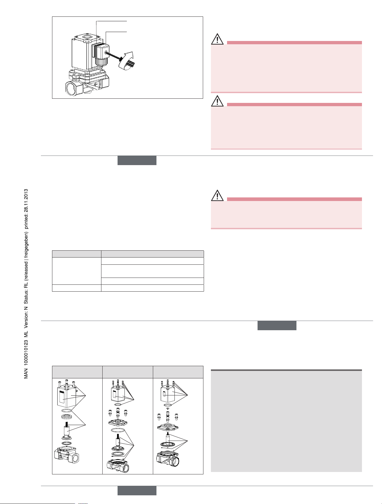
Sealing material must not get into the device.
→ Hold the device with a suitable tool (open-end wrench) on the
body and screw into the pipeline.
NOTE!
Caution risk of breakage!
• Do not use the coil as a lever arm.
→ Observe direction of flow:
The arrow on the body indicates the direction of flow (no function
in opposite flow direction).
5.4 Electrical installation
DANGER!
Risk of injury due to electrical shock!
▶ Before reaching into the system, switch off the power supply and
secure to prevent reactivation!
▶ Observe applicable accident prevention and safety regulations for
electrical equipment!
WARNING!
Danger of electrical shock if the protective conductor contact
between the coil and body is missing!
▶ Always connect protective conductor.
▶ Check electrical continuity between coil and body.
Risk of short-circuit or escape of media through leaking screw
joints.
▶ Ensure seals are seated correctly!
▶ Carefully screw together coil and device socket or valve and
pipelines!
Note the voltage and current type as specified on the label.
Maximum residual ripple for direct current 10 %.
english
Type 0290
Page 4
8
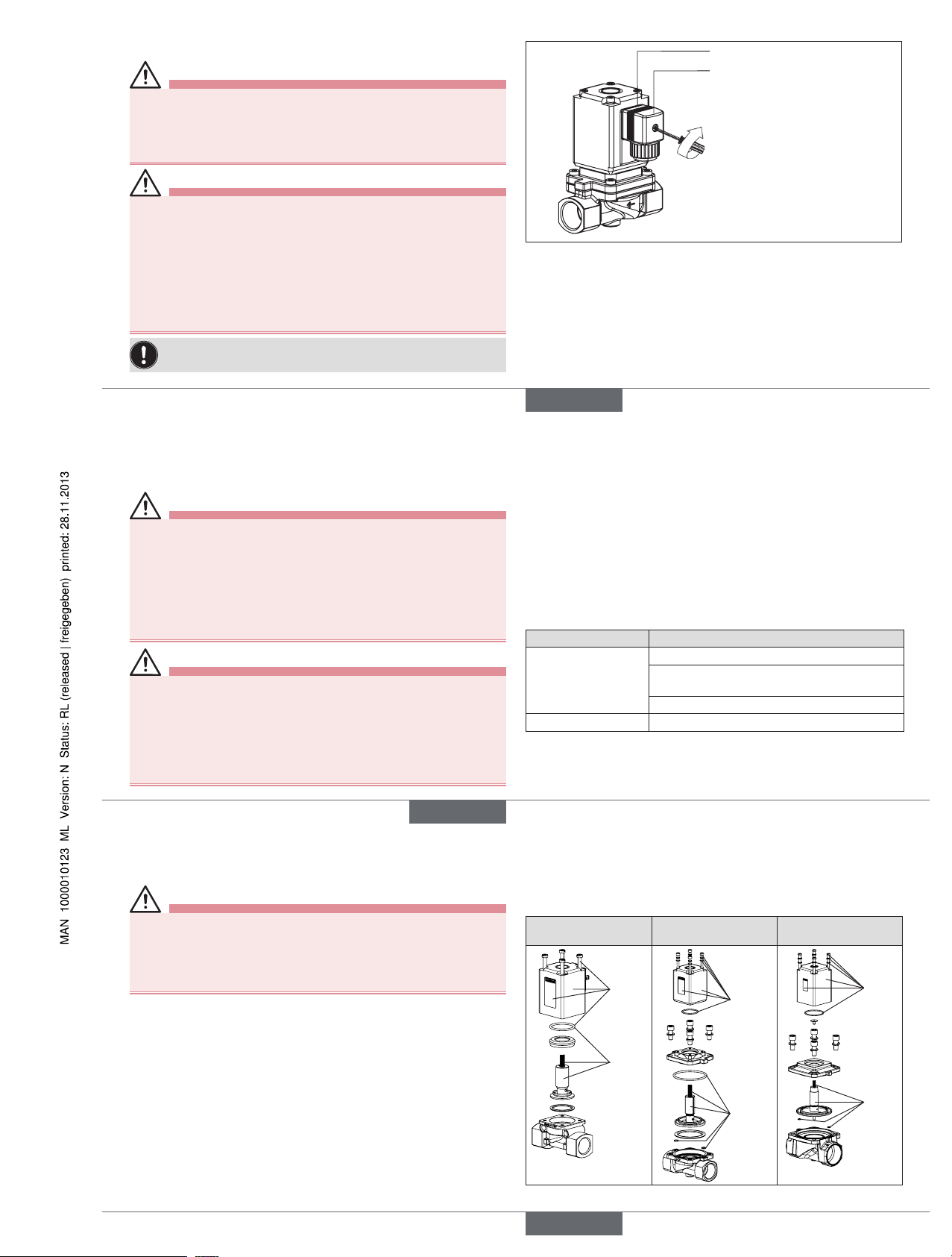
max. 1 Nm
Seal
Authorized cable plug
e.g. Type 2508 or other suitable
cable plug in accordance with
DIN EN 175301-803 Form A
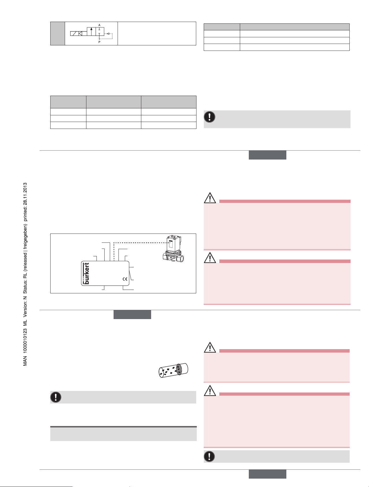
Fig. 1: Electrical installation
→ Tighten cable plug (for permitted types see data sheet), observing
max. torque 1 Nm.
→ Check that seal is fitted correctly.
→ Connect protective conductor and check electrical continuity between
coil and body.
6 MAINTENANCE, TROUBLESHOOTING
6.1 Safety instructions
DANGER!
Risk of injury from high pressure in the equipment!
▶ Before loosening the lines and valves, turn off the pressure and
vent the lines.
Risk of injury due to electrical shock!
▶ Before reaching into the system, switch off the power supply and
secure to prevent reactivation!
▶ Observe applicable accident prevention and safety regulations for
electrical equipment!
WARNING!
Risk of injury from improper maintenance!
▶ Maintenance may be carried out by authorized technicians only and
with the appropriate tools!
Risk of injury from unintentional activation of the system and an
uncontrolled restart!
▶ Secure system from unintentional activation.
▶ Following maintenance, ensure a controlled restart.
english
9
6.2 Malfunctions
If malfunctions occur, check whether:
• the device has been installed according to the instructions,
• the electrical and fluid connections are correct,
• the device is not damaged,
• all screws have been tightened,
• the voltage and pressure have been switched on,
• the pipelines are clean.
Malfunction Possible cause
Valve does not
switch
Short-circuit or coil interrupted
Medium pressure outside the permitted
pressure range
core / core area is dirty
Valve does not close Internal space of the valve is dirty
If the valve still does not switch, please contact your Bürkert Service.
7 SPARE PARTS
CAUTION!
Risk of injury and/or damage by the use of incorrect parts!
Incorrect accessories and unsuitable spare parts may cause injuries and
damage the device and the surrounding area.
▶ Use only original accessories and original spare parts from Bürkert.
7.1 Ordering spare parts
The spare parts sets SET 1 (coil set) or SET 3 (wearing parts set) can
be ordered by quoting the identification number of the device.
english
10
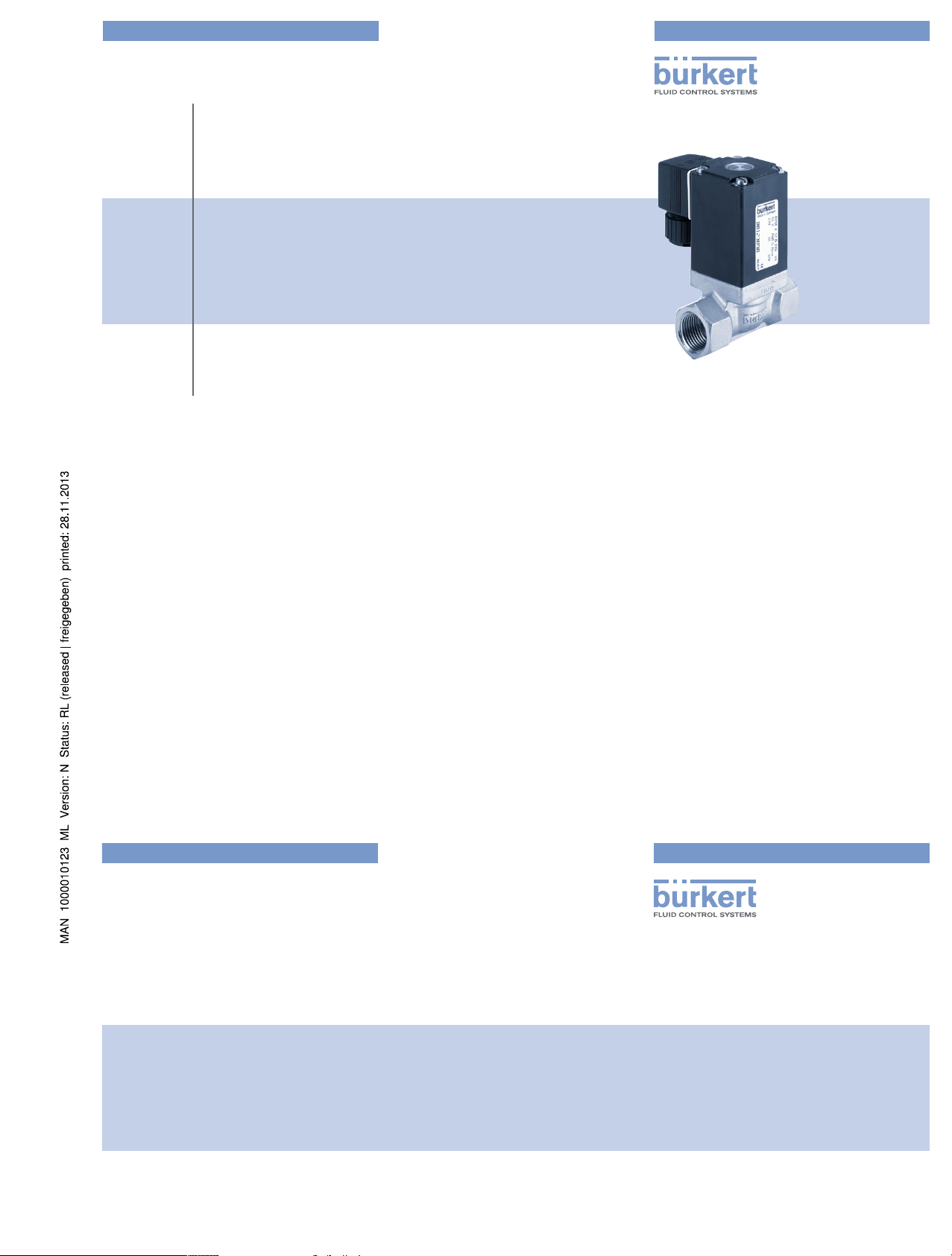
7.2 Overview of replacement spare sets
SET 1 = coil set
SET 3 = wearing parts set
DN 12 DN 20, DN 25
DN 32, DN 40,
DN 50, DN 65
SET 1
SET 3
SET 1
SET 3
SET 1
SET 3
Fig. 2: Overview of replacement spare sets
8 PACKAGING, TRANSPORT,
STORAGE, DISPOSAL
NOTE!
Transport damages!
Inadequately protected equipment may be damaged during
transport.
• During transportation protect the device against wet and dirt in
shock-resistant packaging.
• Avoid exceeding or dropping below the allowable storage
temperature.
Incorrect storage may damage the device.
• Store the device in a dry and dust-free location!
• Storage temperature -40 ... +55 °C.
Damage to the environment caused by device components contaminated with media.
• Dispose of the device and packaging in an environmentally friendly
manner.
• Observe applicable regulations on disposal and the environment.
english
Type 0290
Page 5
Bedienungsanleitung
Manuel d‘utilisation
Operating Instructions
Type 0290
2/2-way solenoid valve
2/2-Wege Magnetventil
Electrovanne à 2/2 voies
www.burkert.com
International address
www.burkert.com
Manuals and data sheets on the Internet: www.burkert.com
Bedienungsanleitungen und Datenblätter im Internet: www.buerkert.de
Instructions de service et fiches techniques sur Internet : www.buerkert.fr
© Bürker t Werke GmbH , 2013
Operating Instr uctions 1311/08_EU-ML_0 0893124 / Original DE
Bürkert Fluid Control Systems
Sales Center
Christian-Bürkert-Str. 13-17
D-74653 Ingelfingen
Tel. + 49 (0) 7940 - 10 91 111
Fax + 49 (0) 7940 - 10 91 448
E-mail: info@de.buerkert.com
Page 6

11
1 DIE BEDIENUNGSANLEITUNG
Die Bedienungsanleitung enthält wichtige Informationen.
▶ Bedienungsanleitung sorgfältig lesen und Hinweise zur Sicherheit
beachten.
▶ Bedienungsanleitung muss jedem Benutzer zur Verfügung stehen.
▶ Haftung und Gewährleistung für das Gerät entfällt, wenn die Anwei-
sungen der Bedienungsanleitung nicht beachtet werden.
1.1 Darstellungsmittel
▶ markiert eine Anweisung zur Gefahrenvermeidung.
→ markiert einen Arbeitsschritt, den Sie ausführen müssen.
Warnung vor Verletzungen:
GEFAHR!
Unmittelbare Gefahr! Schwere oder tödliche Verletzungen.
WARNUNG!
Mögliche Gefahr! Schwere oder tödliche Verletzungen.
VORSICHT!
Gefahr! Mittelschwere oder leichte Verletzungen.
Warnung vor Sachschäden:
HINWEIS!
2 BESTIMMUNGSGEMÄSSER
GEBRAUCH
Bei nicht bestimmungsgemäßem Gebrauch des Typs 0290 können
Gefahren für Personen, Anlagen in der Umgebung und die Umwelt
entstehen.
▶ Das Gerät ist zum Dosieren, Sperren, Füllen und Belüften von
Medien konzipiert.
▶ Mit einer sachgemäß angeschlossenen und montierten Geräte-
steckdose, z. B. Bürkert Typ 2508 erfüllt das Gerät die Schutzart
IP65 nach DIN EN 60529 / IEC 60529.
▶ Für den Einsatz die in den Vertragsdokumenten und der Bedie-
nungsanleitung spezifizierten zulässigen Daten, Betriebs- und
Einsatzbedingungen beachten. Diese sind im Kapitel „4 Technische
Daten“ beschrieben.
▶ Das Gerät nur in Verbindung mit von Bürkert empfohlenen bzw.
zugelassenen Fremdgeräten und -komponenten einsetzen.
▶ Voraussetzungen für den sicheren und einwandfreien Betrieb sind
sachgemäßer Transport, sachgemäße Lagerung und Installation
sowie sorgfältige Bedienung und Instandhaltung.
▶ Setzen Sie das Gerät nur bestimmungsgemäß ein.
2.1 Beschränkungen
Bei Ausfuhr des Geräts ggf. bestehende Beschränkungen beachten.
deutsch
12
3 GRUNDLEGENDE
SICHERHEITSHINWEISE
Diese Sicherheitshinweise berücksichtigen keine Zufälligkeiten und
Ereignisse, die bei Montage, Betrieb und Wartung auftreten können.
Gefahr durch hohen Druck!
▶ Vor Lösen von Leitungen oder Ventilen den Druck abschalten und
Leitungen entlasten.
Gefahr durch elektrische Spannung!
▶ Vor Eingriffen in Gerät oder Anlage Spannung abschalten und vor
Wiedereinschalten sichern!
▶ Die geltenden Unfallverhütungs- und Sicherheitsbestimmungen für
elektrische Geräte beachten!
Verbrennungsgefahr/Brandgefahr bei Dauerbetrieb durch heiße
Geräteoberfläche!
▶ Das Gerät von leicht brennbaren Stoffen und Medien fernhalten und
nicht mit bloßen Händen berühren.
Verletzungsgefahr durch Funktionsausfall bei Ventilen mit
Wechselspannung (AC).
Festsitzender Kern bewirkt Spulenüberhitzung, die zu Funktionsausfall führt.
Arbeitsprozess auf einwandfreie Funktion überwachen!
2.2 Begriffsdefinition „Gerät“
Der in der Anleitung verwendete Begriff „Gerät“ steht immer für Typ
0290.
2.3 Zulassungen
Geräte, die das Typgenehmigungszeichen tragen müssen, wurden beim
Kraftfahrtbundesamt unter der Typgenehmigungsnummer
e1*72/245*2006/96*5791*00
genehmigt und werden mit dem gezeigten Typgenehmigungszeichen in
den Verkehr gebracht.
Einen Auszug der Typgenehmigung erhalten Sie unter der Adresse:
Bürkert Werke GmbH
Zulassungsbeauftragter
Christian-Bürkert-Str. 13-17
D-74653 Ingelfingen
deutsch
13
Kurzschlussgefahr/Austritt von Medium durch undichte
Verschraubungen!
▶ Auf einwandfreien Sitz der Dichtungen achten.
▶ Ventil und Anschlussleitungen sorgfältig verschrauben.
Kurzfristiges Öffnen des Ventils
Durch plötzlichen Druckanstieg bei geschlossenem Ventil kann sich
das Ventil einen kurzen Moment öffnen.
▶ Bei gefährlichen Medien ggf. Schutzvorkehrungen treffen.
Allgemeine Gefahrensituationen.
Zum Schutz vor Verletzungen ist zu beachten:
▶ Dass die Anlage nicht unbeabsichtigt betätigt werden kann.
▶ Installations- und Instandhaltungsarbeiten dürfen nur von autorisier-
tem Fachpersonal mit geeignetem Werkzeug ausgeführt werden.
▶ Das Gerät darf nur in einwandfreiem Zustand und unter Beachtung
der Bedienungsanleitung betrieben werden.
▶ Für die Einsatzplanung und den Betrieb des Geräts müssen die
allgemeinen Regeln der Technik eingehalten werden.
▶ Im explosionsgeschützten Bereich darf das Gerät nur eingesetzt
werden, wenn auf dem Typschild eine entsprechende zusätzliche
Kennzeichnung angebracht ist. Für den Einsatz muss die dem Gerät
beiliegende Zusatzinformation mit Sicherheitshinweisen für den Ex-
Bereich beachtet werden.
▶ Im UL-Bereich muss die beiliegende UL-Anleitung beachtet werden.
▶ Nach einer Unterbrechung der elektrischen oder pneumatischen
Versorgung ist ein definierter oder kontrollierter Wiederanlauf des
Prozesses zu gewährleisten.
Zum Schutz vor Sachschäden am Gerät ist zu beachten:
▶ Das Gerät nicht mechanisch belasten (z. B. durch Ablage von
Gegenständen, als Einschraubhilfe, Trittstufe oder Hebelarm).
▶ Keine äußerlichen Veränderungen an den Gerätegehäusen vorneh-
men. Gehäuseteile und Schrauben nicht lackieren.
Das Magnetventil Typ 0290 wurde unter Einbeziehung der anerkannten sicherheitstechnischen Regeln entwickelt und entspricht
dem Stand der Technik. Trotzdem können Gefahren entstehen.
3.1 Gewährleistung
Voraussetzung für die Gewährleistung ist der bestimmungsgemäße Gebrauch des Geräts unter Beachtung der spezifizierten
Einsatzbedingungen.
3.2 Informationen im Internet
Bedienungsanleitungen und Datenblätter zum Typ 0290 finden Sie im
Internet unter:
www.buerkert.de
deutsch
Typ 0290
Page 7

14
4 TECHNISCHE DATEN
4.1 Betriebsbedingungen
Folgende Werte* sind auf dem Typschild angegeben:
• Spannung (Toleranz ± 10 %) / Stromart
• Spulenleistung (Wirkleistung in W – betriebswarm)
• Druckbereich
• Gehäusewerkstoff Messing (MS) oder Edelstahl (VA)
• Dichtwerkstoff FKM, EPDM, NBR
* siehe nachfolgende Typschildbeschreibung
Wirkungsweise 2/2-Wege-Ventil:
A
(NC)
2/2-Wege-Ventil,
direktwirkend, stromlos Ausgang A
entlastet
Schutzart: IP65 nach DIN EN 60529 / IEC 60529 mit
sachgemäß angeschlossener und montierter
Gerätesteckdose, z. B. Bürkert Typ 2508
Umgebungstemperatur: max. +55 °C
Zulässige Mediumstemperatur in Abhängigkeit von Dichtwerkstoff
und Spulenausführung:
Dicht-
werkstoff
Ausführung mit
Hochleistungsspule oder
Gleichrichter AC/DC*
Ausführung ohne
Elektronik 50 Hz, 60 Hz*
NBR -10 ... +80 °C -10 ... +80 °C
FKM 0 ... +90 °C 0 ... +120 °C
EPDM -30 ... +90 °C -30 ... +100 °C
* Typschildangaben
Zulässige Medien in Abhängigkeit vom Dichtwerkstoff:
Dichtwerkstoff Zulässige Medien
NBR Neutrale Medien, Druckluft, Wasser, Hydrauliköl
FKM Per-Lösungen, heiße Öle
EPDM Öl- und fettfreie Medien, z. B. Heißwasser
deutsch
15
Betriebsdauer
Wenn auf dem Typschild nicht anders angegeben, ist das Magnetsystem
für Dauerbetrieb geeignet.
Bei Ausführung mit Hochleistungsspule sind maximal 6 Schaltungen
pro Minute möglich. Dies betrifft Geräte mit folgender Leistung
(Typschildangabe):
80/6 W 90/7 W 100/9 W
120/8,5 W 120/10 W 130/9 W
Wichtiger Hinweis zur Funktionssicherheit bei Dauerbetrieb!
Bei langem Stillstand wird eine Mindestbetätigung von
1–2 Schaltungen pro Tag empfohlen.
Lebensdauer
Hohe Schaltfrequenz und hohe Drücke verringern die Lebensdauer.
4.2 Konformität
Der Typ 0290 ist konform zu den EG-Richtlinien entsprechend der
EG-Konformitätserklärung.
4.3 Normen
Die angewandten Normen, mit denen die Konformität mit den EGRichtlinien nachgewiesen wird, sind in der EG-Baumusterprüfbescheinigung und/oder der EG-Konformitätserklärung nachzulesen.
4.4 Typschild (Beispiel)
0290 A 20,0 FKM VA
Made in Germany
00153212
W1Y LU
230 V 50 Hz 16 W
G 3/4 P
N 0 - 16 bar
Typ
Wirkungsweise
Nennweite
Dichtwerkstoff
Gehäusewerkstoff
Identnummer
Hersteller-Code
Spannung, Frequenz, Leistung
Leitungsanschluss, Druckbereich
deutsch
16
5 MONTAGE
5.1 Sicherheitshinweise
GEFAHR!
Verletzungsgefahr durch hohen Druck in der Anlage!
▶ Vor dem Lösen von Leitungen oder Ventilen den Druck abschalten
und Leitungen entlüften.
Verletzungsgefahr durch Stromschlag!
▶ Vor Eingriffen in das Gerät oder die Anlage Spannung abschalten
und vor Wiedereinschalten sichern!
▶ Die geltenden Unfallverhütungs- und Sicherheitsbestimmungen für
elektrische Geräte beachten!
WARNUNG!
Verletzungsgefahr bei unsachgemäßer Montage!
▶ Die Montage darf nur autorisiertes Fachpersonal mit geeignetem
Werkzeug durchführen!
Verletzungsgefahr durch ungewolltes Einschalten der Anlage
und unkontrollierten Wiederanlauf!
▶ Anlage vor unbeabsichtigtem Betätigen sichern.
▶ Nach der Montage einen kontrollierten Wiederanlauf gewährleisten.
5.2 Vor dem Einbau
Einbaulage: Die Einbaulage ist beliebig. Vorzugsweise: Antrieb oben.
→ Rohrleitungen vor dem Einbau auf Verschmutzungen überprüfen und
gegebenenfalls reinigen.
Schmutzfilter: Für die sichere Funktion des
Magnetventils muss vor dem Ventileingang ein
Schmutzfilter (≤ 400 µm) eingebaut werden.
5.3 Einbau
Dichtmaterial darf nicht in das Gerät gelangen.
→ Das Gerät mit geeignetem Werkzeug (Gabelschlüssel) am Gehäuse
festhalten, in die Rohrleitung einschrauben.
HINWEIS!
Vorsicht Bruchgefahr!
• Die Spule darf nicht als Hebelarm benutzt werden.
→ Durchflussrichtung beachten:
Der Pfeil auf dem Gehäuse kennzeichnet die Durchflussrichtung
(keine Funktion in entgegengesetzter Durchflussrichtung).
deutsch
Typ 0290
Page 8
17
5.4 Elektrische Installation
GEFAHR!
Verletzungsgefahr durch Stromschlag!
▶ Vor Eingriffen in Gerät oder Anlage Spannung abschalten und vor
Wiedereinschalten sichern!
▶ Die geltenden Unfallverhütungs- und Sicherheitsbestimmungen für
elektrische Geräte beachten!
WARNUNG!
Verletzungsgefahr durch Stromschlag bei fehlendem Schutzleiterkontakt zwischen Spule und Gehäuse!
▶ Schutzleiter immer anschließen!
▶ Schutzleiterkontakt nach der Spulenmontage prüfen!
Kurzschlussgefahr bzw. Austritt von Medium bei undichten
Verschraubungen.
▶ Auf einwandfreien Sitz der Dichtungen achten!
▶ Spule und Gerätesteckdose bzw. Ventil und Rohrleitungen sorgfältig
verschrauben!
Spannung und Stromart laut Typschild beachten.
Maximale Restwelligkeit bei Gleichstrom 10 %.
max. 1 Nm
Dichtung
Zugelassene Gerätesteckdose
z. B. Typ 2508 oder andere
geeignete Gerätesteckdose nach
DIN EN 175301-803 Form A
Bild 1: Elektrische Installation
→ Gerätesteckdose (zugelassene Typen siehe Datenblatt) fest-
schrauben, dabei maximales Drehmoment 1 Nm beachten.
→ Korrekten Sitz der Dichtung überprüfen.
→ Schutzleiter anschließen und elektrischen Durchgang zwischen
Spule und Gehäuse prüfen.
deutsch
18
6 WARTUNG, FEHLERBEHEBUNG
6.1 Sicherheitshinweise
GEFAHR!
Verletzungsgefahr durch hohen Druck in der Anlage!
▶ Vor dem Lösen von Leitungen und Ventilen den Druck abschalten
und Leitungen entlüften.
Verletzungsgefahr durch Stromschlag!
▶ Vor Eingriffen in Gerät oder Anlage Spannung abschalten und vor
Wiedereinschalten sichern!
▶ Die geltenden Unfallverhütungs- und Sicherheitsbestimmungen für
elektrische Geräte beachten!
WARNUNG!
Verletzungsgefahr bei unsachgemäßen Wartungsarbeiten!
▶ Die Wartung darf nur autorisiertes Fachpersonal mit geeignetem
Werkzeug durchführen!
Verletzungsgefahr durch ungewolltes Einschalten der Anlage
und unkontrollierten Wiederanlauf!
▶ Anlage vor unbeabsichtigtem Betätigen sichern.
▶ Nach der Wartung einen kontrollierten Wiederanlauf gewährleisten.
6.2 Störungen
Überprüfen Sie bei Störungen ob
• das Gerät vorschriftsmäßig installiert ist,
• der elektrische und fluidische Anschluss ordnungsgemäß ausgeführt
ist,
• das Gerät nicht beschädigt ist,
• alle Schraubverbindungen fest angezogen sind,
• Spannung und Druck anliegen,
• die Rohrleitungen schmutzfrei sind.
Störung Mögliche Ursache
Ventil schaltet nicht Kurzschluss oder Spulenunterbrechung
Mediumsdruck außerhalb des zulässigen
Druckbereichs
Kern/Kernraum verschmutzt
Ventil schließt nicht Innenraum des Ventils verschmutzt
Falls das Ventil dennoch nicht schaltet, wenden Sie sich bitte an Ihren
Bürkert-Service.
deutsch
19
7 ERSATZTEILE
VORSICHT!
Verletzungsgefahr, Sachschäden durch falsche Teile!
Falsches Zubehör und ungeeignete Ersatzteile können Verletzungen
und Schäden am Gerät und dessen Umgebung verursachen.
▶ Nur Originalzubehör sowie Originalersatzteile der Firma Bürkert
verwenden.
7.1 Ersatzteile bestellen
Die Ersatzteilsätze SET 1 (Spulensatz) oder SET 3 (Verschleißteilsatz)
können Sie unter der Identnummer des Geräts bestellen.
7.2 Übersicht Ersatzteilsätze
SET 1 = Spulensatz
SET 3 = Verschleißteilsatz
DN 12 DN 20, DN 25
DN 32, DN 40,
DN 50, DN 65
SET 1
SET 3
SET 1
SET 3
SET 1
SET 3
Bild 2: Übersicht Ersatzteilsätze
deutsch
Typ 0290
Page 9

20
8 VERPACKUNG, TRANSPORT,
LAGERUNG, ENTSORGUNG
HINWEIS!
Transportschäden!
Unzureichend geschützte Geräte können durch den Transport
beschädigt werden.
• Gerät vor Nässe und Schmutz geschützt in einer stoßfesten
Verpackung transportieren.
• Eine Über- bzw. Unterschreitung der zulässigen Lagertemperatur
vermeiden.
Falsche Lagerung kann Schäden am Gerät verursachen.
• Gerät trocken und staubfrei lagern!
• Lagertemperatur –40 … +55 °C.
Umweltschäden durch von Medien kontaminierte Geräteteile.
• Gerät und Verpackung umweltgerecht entsorgen!
• Geltende Entsorgungsvorschriften und Umweltbestimmungen
einhalten.
deutsch
Typ 0290
Page 10

Bedienungsanleitung
Manuel d‘utilisation
Operating Instructions
Type 0290
2/2-way solenoid valve
2/2-Wege Magnetventil
Electrovanne à 2/2 voies
www.burkert.com
International address
www.burkert.com
Manuals and data sheets on the Internet: www.burkert.com
Bedienungsanleitungen und Datenblätter im Internet: www.buerkert.de
Instructions de service et fiches techniques sur Internet : www.buerkert.fr
© Bürker t Werke GmbH , 2013
Operating Instr uctions 1311/08_EU-ML_0 0893124 / Original DE
Bürkert Fluid Control Systems
Sales Center
Christian-Bürkert-Str. 13-17
D-74653 Ingelfingen
Tel. + 49 (0) 7940 - 10 91 111
Fax + 49 (0) 7940 - 10 91 448
E-mail: info@de.buerkert.com
Page 11

21
1 LE MANUEL D’UTILISATION
Manuel d’utilisation contiennent des informations importantes.
▶ Lire attentivement ce manuel d’utilisation et respecter les consignes
de sécurité.
▶ Le manuel d’utilisation doit être à disposition de chaque utilisateur.
▶ Nous déclinons toute responsabilité et n’accordons aucune garantie
légale pour l’appareil en cas de non-respect des instructions figurant
dans ce manuel d’utilisation.
1.1 Symbols
▶ Identifie une instruction visant à éviter un danger.
→ identifie une opération que vous effectuer.
Mise en garde contre les blessures :
DANGER !
Danger imminent ! Les blessures graves ou mortelles.
AVERTISSEMENT !
Danger possible ! Les blessures graves ou mortelles.
ATTENTION !
Danger ! Les blessures légères ou moyennement graves.
Met en garde contre des dommages matériels :
REMARQUE !
2 UTILISATION CONFORME
L’utilisation non-conforme du type 0290 peut présenter des dangers
pour les personnes, les installations avoisinantes et l’environnement.
▶ L’appareil est conçu pour doser, couper, remplir et aérer des fluides.
▶ Avec une un connecteur adéquat, par ex. le type 2508 de Bürkert,
connectée et montée de manière conforme, l’appareil est conforme
au type de protection IP65 selon DIN EN 60529 / IEC 60529.
▶ L’utilisation doit se faire dans le respect des données et des condi-
tions d’exploitation et d’utilisation spécifiées dans les documents
contractuels, les instructions de service et sur la plaque signalétique.
Vous trouverez une description au chapitre „4 Caractéristiques
techniques“.
▶ L’appareil peut être utilise uniquement en association avec les
appareils et composants étrangers recommandés et homologués par
Bürkert.
▶ Les conditions pour l’utilisation sûre et parfaite sont un transport,
un stockage et une installation dans les règles ainsi qu’une parfaite
utilisation et maintenance.
▶ Veillez à ce que l’utilisation de l’appareil soit toujours conforme.
2.1 Limitations
Lors de l’exportation de l’appareil, veuillez respecter les limitations
éventuelles existantes.
français
22
3 CONSIGNES DE SÉCURITÉ
FONDAMENTALES
Ces consignes de sécurité ne tiennent pas compte des hasards et des
événements pouvant survenir lors du montage, de l’exploitation et de
l’entretien.
Danger avec haute pression !
▶ Avant de desserrer les tuyauteries et les vannes, coupez la pression et
purgez les conduites.
Danger présenté par la tension électrique !
▶ Avant d’intervenir dans l’appareil ou l’installation, coupez la tension et
empêchez toute remise sous tension par inadvertance !
▶ Veuillez respecter les réglementations en vigueur pour les appa-
reils électriques en matière de prévention des accidents ainsi qu’en
matière de sécurité !
Risque de brûlures / d’incendie lors d’une durée de fonctionnement prolongée dû à la surface brûlante de l’appareil !
▶ Tenez les substances et les fluides facilement inflammables à l’écart de
l’appareil et ne touchez pas ce dernier à mains nues.
Risque de blessure dû à une panne pour les vannes avec tension
alternative (AC).
Un noyau bloqué provoque la surchauffe de la bobine et donc une panne.
▶ Surveiller le bon fonctionnement du processus de travail !
2.2 Définition du terme
Le terme « appareil» utilisé dans ce manuel désigne toujours l’électrovanne type 0290.
2.3 Homologations
Les appareil portant le marque e1 ont été homologués au Service fédéral
de la circulation automobile (Kraftfahrtbundesamt) sous le numéro
e1*72/245*2006/96*5791*00
et seront mis en circulation avec la marque d’homologation indiquée
Vous recevrez un extrait de l’homologation à l’adresse ci-dessous:
Bürkert Werke GmbH
Zulassungsbeauftragter
Christian-Bürkert-Str. 13-17
D-74653 Ingelfingen
français
23
Risque de court-circuit / de sortie du fluide en présence de
vissages non étanches.
▶ Veiller à l’installation correcte des joints !
▶ Visser soigneusement la vanne et les raccords de la tuyauterie !
Ouverture à court terme de la vanne
En cas d’augmentation soudaine de la pression alors que la vanne est
fermée, cette dernière peut s’ouvrir pendant un court instant.
▶ En cas de présence de fluides dangereux, prendre le cas échéant des
mesures de protection.
Situations dangereuses d’ordre général.
Pour prévenir les blessures, respectez ce qui suit :
▶ L’installation ne peut pas être actionnée par inadvertance.
▶ Les travaux d’installation et de maintenance doivent être effectués
uniquement par des techniciens qualifiés et habilités disposant de
l’outillage approprié.
▶ L’appareil doit être utilisé uniquement en parfait état et en respectant
les instructions de service.
▶ Les règles générales de la technique sont à appliquer pour l’opéra-
tionnel et l’utilisation de l’appareil.
▶ L’appareil ne peut être utilisé dans une zone à atmosphère explosive
que si un marquage additionnel correspondant se trouve sur la plaque
signalétique. Lors de l’utilisation, il convient de respecter les informations suplémentaires fournies avec l’appareil et reprenant les
consignes de sécurité pour la zone exposée à des risques d’explosion.
▶ Après une interruption de l’alimentation électrique ou du fluide, un
redémarrage défini ou contrôlé du process doit être garanti.
▶ La notice UL jointe doit être respectée dans la zone UL.
Pour prévenir les dommages matériels, respectez ce qui suit :
▶ Ne soumettez pas l’appareil à des contraintes mécaniques (par ex.
en déposant des objets dessus ou en l’utilisant comme auxiliaire de
vissage, comme marche ou encore comme levier).
▶ N’apportez pas de modifications à l’extérieur du corps de l‘appareil.
Ne laquez pas les pièces du corps et les vis.
Le modèle 0290 a été développé dans le respect des règles
reconnues en matière de sécurité et correspond à l’état actuel
de la technique. Néanmoins, des risques peuvent se présenter.
3.1 Garantie légale
La condition pour bénéficier de la garantie légale est l’utilisation conforme
du type 0290 dans le respect des conditions d’utilisation spécifiées.
3.2 Informations sur Internet
Vous trouverez sur Internet les instructions de service et fiches techniques
relatives au type : www.buerkert.fr
français
Type 0290
Page 12

24
4 CARACTÉRISTIQUES TECHNIQUES
4.1 Conditions d’exploitation
Les valeurs suivantes* sont indiquées sur la plaque signalétique :
• Tension (Tolérance ± 10 %) / Type de courant
• Puissance de bobine (Puissance active en W - à l’état chaud)
• Plage de pression
• Matériau du corps Laiton (MS) ou acier inoxydable (VA)
• Matériau du joint FKM, EPDM, NBR
* voir ci-dessous la description de la plaque signalétique
Fonction vanne 2/2:
A
(NC)
Electrovanne 2/2, normalement
fermée par action du ressort
Type de protection: IP65 selon DIN EN 60529 / IEC 60529
avec une connecteur montée de manière
conforme, par ex. le type 2508 de Bürkert
Température ambiante : max. +55 °C
Valeur admissible de la temp. du fluide en fonction du matériau
d’étanchéité et de l’exécution de la bobine:
Matériau
d’étanchéité
Exécution avec Bobine
haute performance ou
redresseur AC/DC*
Exécution sans
électronique
50 Hz, 60 Hz*
NBR -10 ... +80 °C -10 ... +80 °C
FKM 0 ... +90 °C 0 ... +120 °C
EPDM -30 ... +90 °C -30 ... +100 °C
* Indications de la plaque signalétique
Fluides utilisables en fonction du matériau du joint :
Matériau du joint Fluides admissibles
NBR Fluides neutres, air comprimé, eau, huile hydraulique
FKM Solution perchloréthylène, huiles chaudes
EPDM Fluides sans huile ni graisse, ex. eau chaude
français
25
Durée de fonctionnement
Si aucune information contraire ne figure sur la plaque signalétique, le
système magnétique est adapté à un fonctionnement continu.
La version avec bobine haute performance autorise un maximum de 6
commutations par minute. Cela concerne les appareils aux puissances
suivantes (information sur la plaque signalétique) :
80/6 W 90/7 W 100/9 W
120/8,5 W 120/10 W 130/9 W
Remarque importante pour la sécurité de fonctionnement
lors d’un fonctionnement continu !
Dans le cas d’un fonctionnement de longue durée, il est recommandé de procéder à 1 - 2 commutations minimum par jour.
Durée de vie
Une fréquence élevée de commutation ainsi que des pressions élevées
réduisent la durée de vie.
4.2 Conformité
Le type 0290 est conforme aux directives CE sur la base de la déclaration
de conformité CE.
4.3 Normes
Les normes appliquées justifiant la conformité aux directives CE
peuvent être consultées dans le certificat d’essai de modèle type CE
et / ou la déclaration de Conformité CE.
4.4 Plaque signalétique (Exemple)
0290 A 20,0 FKM VA
Made in Germany
00153212
W1Y LU
230 V 50 Hz 16 W
G 3/4 P
N 0 - 16 bar
Type
Fonction
Diamètre nominal
Matériau du joint
Matériau du corps
Numéro d’identification
Code-fabricant
Tension, fréquence, puissance
Raccordement,
plage de pression
français
26
5 INSTALLATION
5.1 Consignes de sécurité
DANGER !
Risque de blessures avec présence de haute pression dans
l’installation !
▶ Avant de desserrer les tuyauteries et les vannes, coupez la pression et
purgez les conduites.
Risque de choc électrique !
▶ Avant d’intervenir dans l’appareil ou l’installation, coupez la tension et
empêchez toute remise sous tension par inadvertance !
▶ Veuillez respecter les réglementations en vigueur pour les appa-
reils électriques en matière de prévention des accidents ainsi qu’en
matière de sécurité !
AVERTISSEMENT !
Risque de blessures pour montage non conforme !
▶ Le montage doit être effectué uniquement par un personnel qualifié et
habilité disposant de l’outillage approprié !
Risque de blessures dû à la mise en marche involontaire de
l’installation et le redémarrage non contrôlé !
▶ Empêchez tout actionnement involontaire de l’installation.
▶ Garantissez un redémarrage contrôlé après le montage.
5.2 Avant le montage
Position de montage : indifférente.
De préférence : système magnétique vers le haut.
→ Préalablement au montage, vérifier si les tuyaux ne présentent pas
de salissures et les nettoyer le cas échéant
Filtre à impuretés : Pour garantir un fonctionnement
fiable de l’électrovanne, il convient de monter un filtre
à impuretés (≤ 400 µm) avant l’entrée de la vanne.
5.3 Montage
Le matériau d’étanchéité ne doit pas entrer dans l’appareil.
→ Maintenez l’appareil sur le corps à l’aide d’un outil approprié (clé à
fourche) et vissez-le dans la tuyauterie.
REMARQUE !
Attention risque de rupture !
• La bobine ne doit pas être utilisée comme levier.
→ Respectez le sens du débit : La flèche sur le corps indique le sens
du débit (Aucun fonctionnement dans le sens de débit inverse).
français
Type 0290
Page 13

27
5.4 Installation électriques
DANGER!
Risque de choc électrique !
▶ Avant d’intervenir dans l’appareil ou l’installation, coupez la tension
et empêchez toute remise sous tension par inadvertance !
▶ Veuillez respecter les réglementations en vigueur pour les appareils
électriques en matière de prévention des accidents ainsi qu’en
matière de sécurité !
AVERTISSEMENT !
Il y a risque de choc électrique en l’absence d’un contact du
conducteur de protection entre la bobine et le corps !
▶ Raccordez toujours le conducteur de protection !
▶ Contrôler le passage du courant entre la bobine et le corps !
Risque de court-circuit ou de sortie de fluide lorsque les raccords
vissés ne sont pas étanches.
▶ Veiller au parfait positionnement des joints !
▶ Visser avec soin la bobine et la prise d’appareil, respectivement la
vanne et les tuyauteries !
Respectez la tension et le type de courant selon la plaque
signalétique.
Ondulation résiduelle maximale avec courant continu 10 %.
max. 1 Nm
Joint
Connecteur autorisé
par ex. type 2508 ou autres
connecteurs adéquates selon
DIN EN 175301-803 forme A
Fig. 1 : Installation électriques
→ Visser le connecteur (types admissibles, voir fiche technique) en
respectant le couple max. de 1 Nm.
→ Vérifier le bon positionnement du joint.
→ Raccorder la prise de terre de protection et vérifier le passage élec-
trique entre la bobine et le corps.
français
28
6 MAINTENANCE, DÉPANNAGE
6.1 Consignes de sécurité
DANGER !
Risque de blessures dû à la présence de haute pression dans
l'installation !
▶ Avant de desserrer les conduites et les vannes, coupez la pression et
purgez les conduites.
Risque de choc électrique !
▶ Avant d'intervenir dans l'appareil ou l'installation, coupez la tension et
empêchez toute remise sous tension par inadvertance !
▶ Veuillez respecter les réglementations en vigueur pour les appareils
électriques en matière de prévention des accidents ainsi qu'en matière
de sécurité !
AVERTISSEMENT !
Risque de blessures dû à des travaux de maintenance non conformes !
▶ La maintenance doit être effectué uniquement par un personnel qualifié
et habilité disposant de l'outillage approprié !
Risque de blessures dû à la mise en marche involontaire de l'installation et le redémarrage non contrôlé !
▶ Empêchez tout actionnement involontaire de l'installation.
▶ Garantissez un redémarrage contrôlé après la maintenance.
6.2 Pannes
En présence de pannes, vérifiez :
• si l‘appareil est installé dans les règles,
• si le raccord électrique et fluide est correct,
• si l‘appareil n‘est pas endommagé,
• si toutes les vis sont bien serrées,
• si la tension et la pression sont disponibles,
• si les tuyauteries sont propres.
Panne Cause possible
La vanne
ne s’enclenche pas
Court-circuit ou coupure de la bobine
Pression du fluide hors de la plage de pression
autorisée
Le noyau / l’espace du noyau est encrassé
La vanne ne se ferme
pas
Intérieur de la vanne encrassé
Si malgré tout la vanne ne commute pas, veuillez vous adresser à votre
service Bürkert.
français
29
7 PIÈCES DE RECHANGE
ATTENTION !
Risque de blessures, de dommages matériels dus à de
mauvaises pièces !
De mauvais accessoires ou des pièces de rechange inadaptées
peuvent provoquer des blessures et endommager l'appareil ou son
environnement.
▶ Utiliser uniquement des accessoires et des pièces de rechange
d'origine de la société Bürkert.
7.1 Commander des pièces de rechange
Les jeux de pièces de rechange SET 1 (jeu de bobines) ou SET 3 (jeu
de pièces d’usure) peuvent être commandés en indiquant le numéro
d’identification de l’appareil.
7.2 Aperçu jeux de pièces de rechange
SET 1 = jeu de bobines
SET 3 = jeu de pièces d’usure
DN 12 DN 20, DN 25
DN 32, DN 40,
DN 50, DN 65
SET 1
SET 3
SET 1
SET 3
SET 1
SET 3
Fig. 2 : Aperçut jeux de pièces de rechange
français
Type 0290
Page 14

30
8 EMBALLAGE, TRANSPORT,
STOCKAGE, ÉLIMINATION
REMARQUE !
Dommages dus au transport !
Les appareils insuffisamment protégés peuvent être endommagés
pendant le transport.
• Transportez l'appareil à l'abri de l'humidité et des impuretés et dans
un emballage résistant aux chocs.
• Évitez le dépassement vers le haut ou le bas de la température de
stockage admissible.
Un mauvais stockage peut endommager l'appareil.
• Stockez l'appareil au sec et à l'abri des poussières !
• Température de stockage : -40 … +55 °C.
Dommages à l'environnement causés par des pièces d'appareil
contaminées par des fluides.
• Eliminez l'appareil et l'emballage dans le respect de l'environnement.
• Respectez les prescriptions en matière d'élimination des déchets et
de protection de l'environnement en vigueur.
français
Type 0290
 Loading...