

Burkert 0287 User Manual [en, de, fr]
Bedienungsanleitung
Manuel d‘utilisation
Operating Instructions
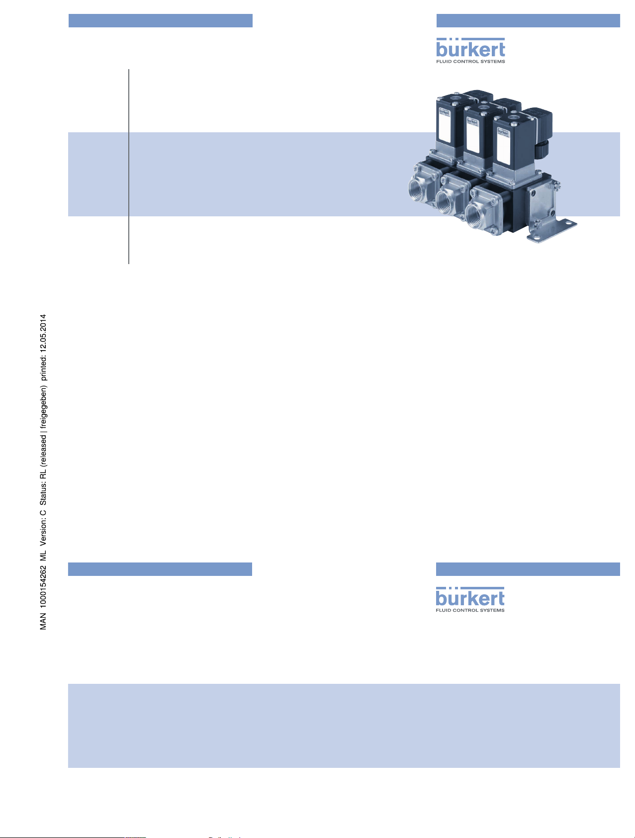
Type 0287
2/2-way solenoid valve, stackable
2/2-Wege-Magnetventil, anreihbar
Électrovanne 2/2 voies, juxtaposable
www.burkert.com
International address
www.burkert.com
Manuals and data sheets on the Internet: www.burkert.com
Bedienungsanleitungen und Datenblätter im Internet: www.buerkert.de
Manuel d'utilisation et fiches techniques sur Internet : www.buerkert.fr
© Bürker t Werke GmbH , 2014
Operating Instr uctions 1405/01_EU-ML_00893190 / Original DE
Bürkert Fluid Control Systems
Sales Center
Christian-Bürkert-Str. 13-17
D-74653 Ingelfingen
Tel. + 49 (0) 7940 - 10 91 111
Fax + 49 (0) 7940 - 10 91 448
E-mail: info@de.buerkert.com
2
1 OPERATING INSTRUCTIONS
The operating instructions contain important information.
▶ Read the operating instructions carefully and follow the safety instruc-
tions in particular, and also observe the operating conditions.
▶ Operating instructions must be available to each user.
▶ The liability and warranty for the device are void if the operating instruc-
tions are not followed.
1.1 Symbols
▶ Designates an instruction to prevent risks.
→ designates a procedure which you must carry out.
Warning of injuries:
Danger!
Imminent danger! Serious or fatal injuries.
Warning!
Potential danger! Serious or fatal injuries.
Caution!
Danger! Minor or moderately severe injuries.
Warns of damage to property:
note!
2 INTENDED USE
Incorrect use of the solenoid valve Type 0287 can be dangerous
to people, nearby equipment and the environment.
▶ The device is designed to control, shut off and meter neutral media up
to a viscosity of 21 mm
2
/s.
▶ Provided the cable plug is connected and installed correctly, e.g. Bürk-
ert Type 2508, the device satisfies protection class IP65 in accordance
with DIN EN 60529 / IEC 60529.
▶ Use according to the permitted data, operating conditions and con-
ditions of use specified in the contract documents and operating
instructions.
▶ Correct transportation, correct storage and installation and careful use
and maintenance are essential for reliable and problem-free operation.
▶ Use the device only as intended.
2.1 Definition of term
In these operating instructions, the term “device” always refers to the
solenoid valve Type 0287.
english
3
Risk of injury due to malfunction of valves with alternating
current (AC)!
Sticking core causes coil to overheat, resulting in a malfunction.
▶ Monitor process to ensure function is in perfect working order!
Risk of short-circuit/escape of media through leaking screw joints!
▶ Ensure seals are seated correctly.
▶ Carefully screw valve and connection lines together.
General hazardous situations.
To prevent injury, ensure that:
▶ Do not make any internal or external changes. Ensure that the system
cannot be activated unintentionally.
▶ Installation and repair work may be carried out by authorized techni-
cians only and with the appropriate tools.
▶ After an interruption in the power supply or pneumatic supply, ensure
that the process is restarted in a defined or controlled manner.
▶ Do not put any loads on the body.
3 BASIC SAFETY INSTRUCTIONS
These safety instructions do not make allowance for any contingencies
and events which may arise during installation, operation and maintenance.
Danger – high pressure!
▶ Before loosening the lines and valves, turn off the pressure and
vent the lines.
Risk of electric shock!
▶ Before reaching into the system, switch off the power supply and
secure to prevent reactivation!
▶ Observe applicable accident prevention and safety regulations for
electrical equipment!
Risk of burns/Risk of fire if used continuously through hot device
surface!
▶ Keep the device away from highly flammable substances and media
and do not touch with bare hands.
english
4
▶ The general rules of technology apply to application planning and
operation of the device.
▶ The device may only be used in the explosion-protected area if an
appropriate additional identification is attached to the type label.
For use observe the additional information enclosed with the device
together with safety instructions for the explosion risk area.
3.1 Warranty
The warranty is only valid if the device is used as intended in accordance
with the specified application conditions.
3.2 Information on the internet
The operating instructions for type 0287 can be found on the internet at:
www.burkert.com
Type 0287
4 SYSTEM DESCRIPTION
4.1 General description
The solenoid valve modules
(SV modules) are stacked
in blocks with the aid of pull
rods and connection pieces.
The valve has the following
functions:
• Distributor (1 input, 2-10
outputs)
• Collector (1 output, 2-10
inputs)
• mixed (2-10 SV modules)
Collector
Collector
Distributor
Distributor
The SV modules with collector function have a non-return valve connected upstream as standard. As a result, the minimum pressure
difference increases to 1 bar.
english
Type 0287
5
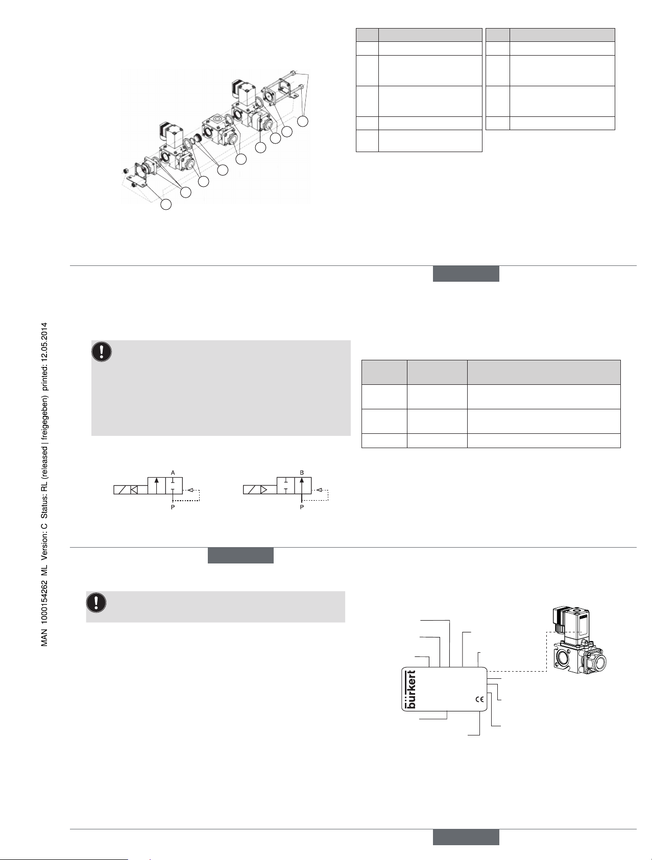
4.2 Block assembly
The following drawing shows in an example the components which belong
to a block and the place where the accessories can be used.
1
9
8
7
6
2
3
5
4
Pos. Description Pos. Description
1 2 Pull rods 6 Partition wall with O-ring
2 Dummy plate or connection
without Quad ring
7 SV module with or without
adapter
1)
or T-module with
Quad ring
3 SV module with or without
adapter
1)
or T-module 2) with
Quad ring
8 Dummy plate or connection
with Quad ring
4 Additional connection 9 2 mounting brackets
5 SV module or T-module with
Quad ring
1)
The adapter allows:
- an injecting device to be connected for taking samples
- a sensor to be installed for measuring certain physical or chemical values of
the medium
2)
T-module: Feed module with G1/2“ connection, others on request
english
6
5 TECHNICAL DATA
5.1 Operating conditions
The following values are indicated on the type label:
• Voltage (Tolerance ± 10 %) / Current type
• Coil power consumption (active power in W - at operating temp.)
• Pressure range
• Body material: Glass fiber reinforced polyamide,
connections: Brass (MS)
• Sealing material: FKM, EPDM, NBR
• Function of the valve: Collectors or distributors can be mixed
on the block
Circuit function 2/2-way valve:
A (NC) B (NO)
Protection class: IP65 in accordance with DIN EN 60529 / IEC
60529 with cable plug, e.g. Bürkert Type 2508
5.2 Application conditions
Ambient temperature: max. +55 °C
Permitted medium temperature and permitted media depending on
sealing material:
Sealing
material
Medium
temperature
Permitted media
FKM 0 ... +70 °C
Diesel and heating oil without additives,
water with additives
EPDM 0 ... +70 °C
Oil and grease-free liquids, cold and
hot water
NBR 0 ... +70 °C Water
Operating duration:
Unless otherwise indicated on the type label,
the solenoid system is suitable for continuous
operation.
For models with a high-power coil a maximum of
6 switching operations per minute are possible.
This applies to devices with power rating
80/6 W
.
english
7
Important information for functional reliability during continuous
operation: If standstill for a long period at least 1-2 activations
per day are recommended.
Service life: High switching frequency and high pressures
reduce the service life
5.3 Conformity
In accordance with the EC Declaration of conformity, Type 0287 is compliant with the EC Directives.
5.4 Standards
The applied standards, which verify conformity with the EC Directives,
can be found on the EC-Type Examination Certificate and / or the EC
Declaration of Conformity.
5.5 Type label
Typ e
Circuit
function
Orifice
Sealing material
Body material
Id. Number
Manufacturer code
Voltage, Frequency,
Power consumption
Connection thread, Operating
pressure
0287 A 13,0 NBR MS
Made in Germany
00017317
W17MG
24 V 50-60 Hz 5W
Verteiler
G1/2 P
N 0.5 - 10 bar
Function of the valve
english
Type 0287
8
6 INSTALLATION
6.1 Safety instructions
Danger!
Risk of injury from high pressure in the equipment!
▶ Before loosening the pipes and valves, turn off the pressure and vent
the lines.
Risk of injury due to electrical shock!
▶ Before reaching into the device or the equipment, switch off the power
supply and secure to prevent reactivation.
▶ Observe applicable accident prevention and safety regulations for
electrical equipment.
Warning!
Risk of injury from improper installation!
▶ Installation may be carried out by authorized technicians only and with
the appropriate tools.
Risk of injury from unintentional activation of the system and an
uncontrolled restart!
▶ Secure system from unintentional activation.
▶ Following assembly, ensure a controlled restart.
6.2 Before installation
Installation position: any, actuator preferably upwards.
Procedure:
→ Check pipelines for dirt and clean.
→ Install a dirt filter before the valve inlet (≤ 400 µm).
6.3 Installation
note!
Caution risk of breakage!
• Do not use the coil as a lever arm.
→ Hold the device using a suitable tool on the body and screw into
the pipeline (maximum permitted torque for line connection 40 Nm).
Valve body must not be installed under tension.
Sealing material must not get into the device.
→ Observe function of the valve (see specifications on the type label).
english
9
Devices with solder connection:
note!
Danger of overheating!
• During the soldering process disconnect the solder connections
from the valve.
6.4 Electrical connection of the cable plug
Warning!
Risk of injury due to electrical shock!
▶ Before reaching into the system, switch off the power supply and
secure to prevent reactivation.
▶ Observe applicable accident prevention and safety regulations for
electrical equipment.
If the protective conductor is not connected, there is a risk of electric
shock!
▶ Always connect protective conductor and check electrical continuity.
Procedure:
→ Tighten cable plug (e.g. Type 2508 or other suitable cable plug),
observing max. torque 1 Nm.
→ Check that seal is fitted correctly.
→ Connect protective conductor and check electrical continuity.
Authorized cable plug
e.g. Type 2508 or other suitable
cable plug in accordance with
DIN EN 175301-803 Form A
Seal
max. 1 Nm
english
10
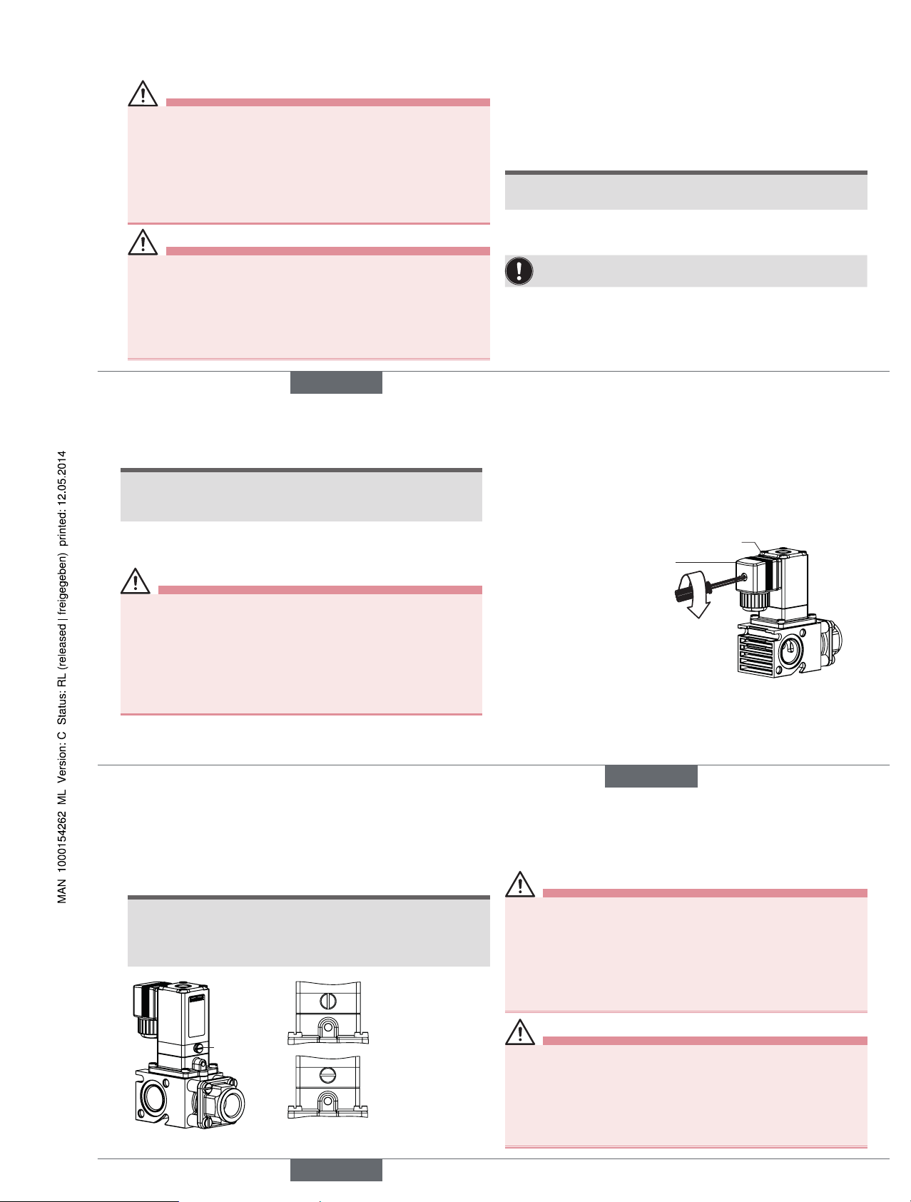
6.5 Manual control HA15, optional
To control the valve manually, turn the rotary knob using a screwdriver
into the vertical position.
note!
Caution!
• Do not overturn the rotary knob.
• When the rotary knob is actuated, the valve can no longer be
switched electrically.
Rotary knob
Manual control
actuated
Manual control not
actuated
7 MAINTENANCE, TROUBLESHOOTING
7.1 Safety instructions
Danger!
Risk of injury from high pressure in the equipment!
▶ Before loosening the lines and valves, turn off the pressure and vent
the lines.
Risk of injury due to electrical shock!
▶ Before reaching into the system, switch off the power supply and
secure to prevent reactivation!
▶ Observe applicable accident prevention and safety regulations for
electrical equipment!
Warning!
Risk of injury from improper maintenance!
▶ Maintenance may be carried out by authorized technicians only and
with the appropriate tools!
Risk of injury from unintentional activation of the system and an
uncontrolled restart!
▶ Secure system from unintentional activation.
▶ Following maintenance, ensure a controlled restart.
english
Type 0287
11
7.2 Malfunctions
If malfunctions occur, check whether:
• the device has been installed according to the instructions,
• the electrical and fluid connections are correct,
• the device is not damaged,
• all screws have been tightened,
• the voltage and pressure have been switched on,
• the pipelines are clean.
Malfunction Possible cause
Valve does not switch Short-circuit or coil interrupted
Medium pressure outside the permitted
pressure range
Core / core area is dirty
Flow restrictor hole in diaphragm dirty
Valve does not close Internal space of the valve is dirty
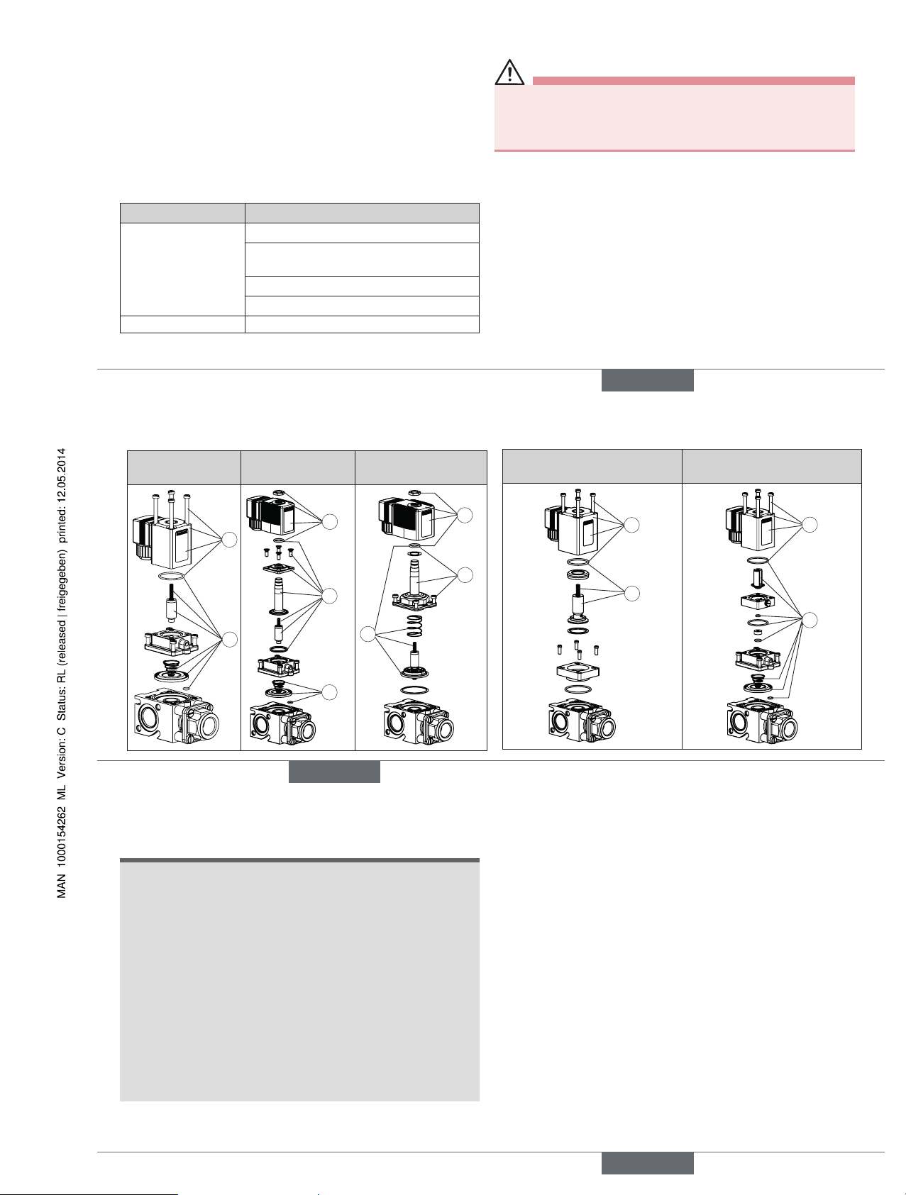
8 SPARE PARTS
Caution!
Risk of injury and/or damage by the use of incorrect parts!
Incorrect accessories and unsuitable spare parts may cause injuries and
damage the device and the surrounding area.
▶ Use only original accessories and original spare parts from Bürkert.
8.1 Ordering spare parts
The following spare parts are available for the solenoid valve Type
0287:
• Coil set (Pos. 1)
• Wearing parts set (Pos. 2 and Pos. 3)
Order the coil set or wearing parts set quoting the identification
number of the device.
english
12
8.2 Overview of spare parts
Standard MT84 with push-
over coil
MT05 core membrane
coupling with spring
1
2
1
2
3
1
2
3
MT08 core membrane
coupling with O-ring
HA15 with manual control
3
1
1
3
english
13
9 TRANSPORT, STORAGE, DISPOSAL
note!
Transport damages!
Inadequately protected equipment may be damaged during
transport.
• During transportation protect the device against wet and dirt in
shock-resistant packaging.
• Avoid exceeding or dropping below the allowable storage
temperature.
Incorrect storage may damage the device.
• Store the device in a dry and dust-free location!
• Storage temperature -40 - +80 °C.
Damage to the environment caused by device components contaminated with media.
• Dispose of the device and packaging in an environmentally friendly
manner.
• Observe applicable regulations on disposal and the environment.
english
Type 0287
 Loading...