

Page 1
BUNN® TECHNICAL TRAINING
Ultra
Page 2

Index
Unit 1: Installation
Site Requirements .............................................................................................................. 4
Location of the Serial Number .......................................................................................... 4
Prepping for Install ............................................................................................................. 5
Hopper Assembly ............................................................................................................... 5
Electrical Install .................................................................................................................. 6
PAF Install ...........................................................................................................................6
LAF Install ...........................................................................................................................7
Unit 2: Setup
User Interface ......................................................................................................................13
Setup ....................................................................................................................................14
LAF Setup Menus ......................................................................................................... 14
Set Thickness ............................................................................................................... 14
Set Date & Time ............................................................................................................ 14
Product Preparation ........................................................................................................... 17
PAF Powder Mix Setup .......................................................................................................17
LAF Liquid Concentrate Setup .......................................................................................... 18
Start Up ................................................................................................................................19
Unit 3: Machine Composition
Exterior Overview ............................................................................................................... 21
Product Outlets and Removable Parts ...................................................................... 21
Removing the Enclosure ................................................................................................... 21
Left Side Panel .................................................................................................................... 22
Right Side Panel ................................................................................................................. 23
Top Motor Covers ............................................................................................................... 23
Compressor ........................................................................................................................24
LED Assembly..................................................................................................................... 25
Machine Functions & Operations ..................................................................................... 25
Unit 4: Preventive Maintenance
PM Parts .............................................................................................................................. 29
PM Steps .............................................................................................................................29
Unit 5: Troubleshooting
Service Tools ......................................................................................................................32
Temp & Torque Screen ....................................................................................................... 33
Warning Messages .............................................................................................................34
Error Messages ...................................................................................................................35
Torque Sensor Board ......................................................................................................... 37
Thermistor ........................................................................................................................... 37
Compressor Windings .......................................................................................................38
External Thermal Protector ............................................................................................... 38
PAF Error Messages ........................................................................................................... 40
Ultra 1 Triac Map .................................................................................................................40
Ultra 2 Triac Map .................................................................................................................41
Ultra PAF Triac Map ............................................................................................................42
Rev. A
© 2013 Bunn-O-Matic Corporation. All Rights Reserved
Page 3

Unit 1 installation
Unit Objectives
Given a realistic scenario depicting a new site install, the learner will be able to install and setup the ULTRA for customer turnover without error.
Given a new machine, all the necessary tools and safety equipment, the learner will be able to install the
ULTRA without error.
The learner will be able to verify that the site requirements have been met for ULTRA or Optional
Accessories.
The learner will be able to locate and document the serial number.
The learner will be able to power up and perform the initial set-up of the ULTRA and Optional Accessory
Systems PAF and LAF.
Page 4
Installation
Site Requirements
Space
• Counter able to support 180 lbs (PAF Accessory Included).
• Minimum clearance of 6” between the machine side and the wall or another appliances
• Counter area able to accommodate machine’s footprint with six inches of clearance in the rear
for air ow and air lter cleaning.
• Dispenser performs better if not placed near any heating appliance that exhausts heat on and
around dispenser.
• Ultra-1 approx. dimensions (H 32 x W 8 x D 24.5)
• Ultra-2 approx. dimensions (H 32 x W 16 x D 24.5)
Plumbing (PAF Only)
• A shut-off valve should be installed in the line before the machine.
• Cold water with an operating pressure between 20 and 90 psi (138 and 690kpa) from a 1/2 inch
or larger supply line with a shut off valve.
• A strainer assembly should be installed in line prior to the exible water line.
Plumbing (LAF with Water to Product Ratio Brix Pump with Shut Off)
• Cold water with an operating pressure between 20 and 90 psi (138 and 690kpa) from a ½ inch or
larger supply line with a shut off valve.
• Water pressure regulator required and set to 50 psi (345kpa) or SHURo water pressure
reducing valve.
• Double check valve with vent required after pressure regulator.
• 3 - Way Sanitizing Valve required within 6 inches of the brix pump
• Use 3/8 inch I.D. FDA approved exible beverage tubing and stainless steel ttings with Oetiker
clamps.
Water Treatment
• Cold water hook-up only.
• Adequate space for water lter and maintenance.
• Water lter or water cartridge purged before machine installation.
• Installation date recorded on water lter decal.
Electrical
• 120VAC
• Dedicated 15AMP Circuit with proper breaker and receptacle
• Receptacle within 5 feet of machine
• Mating connector must be NEMA 5-15R
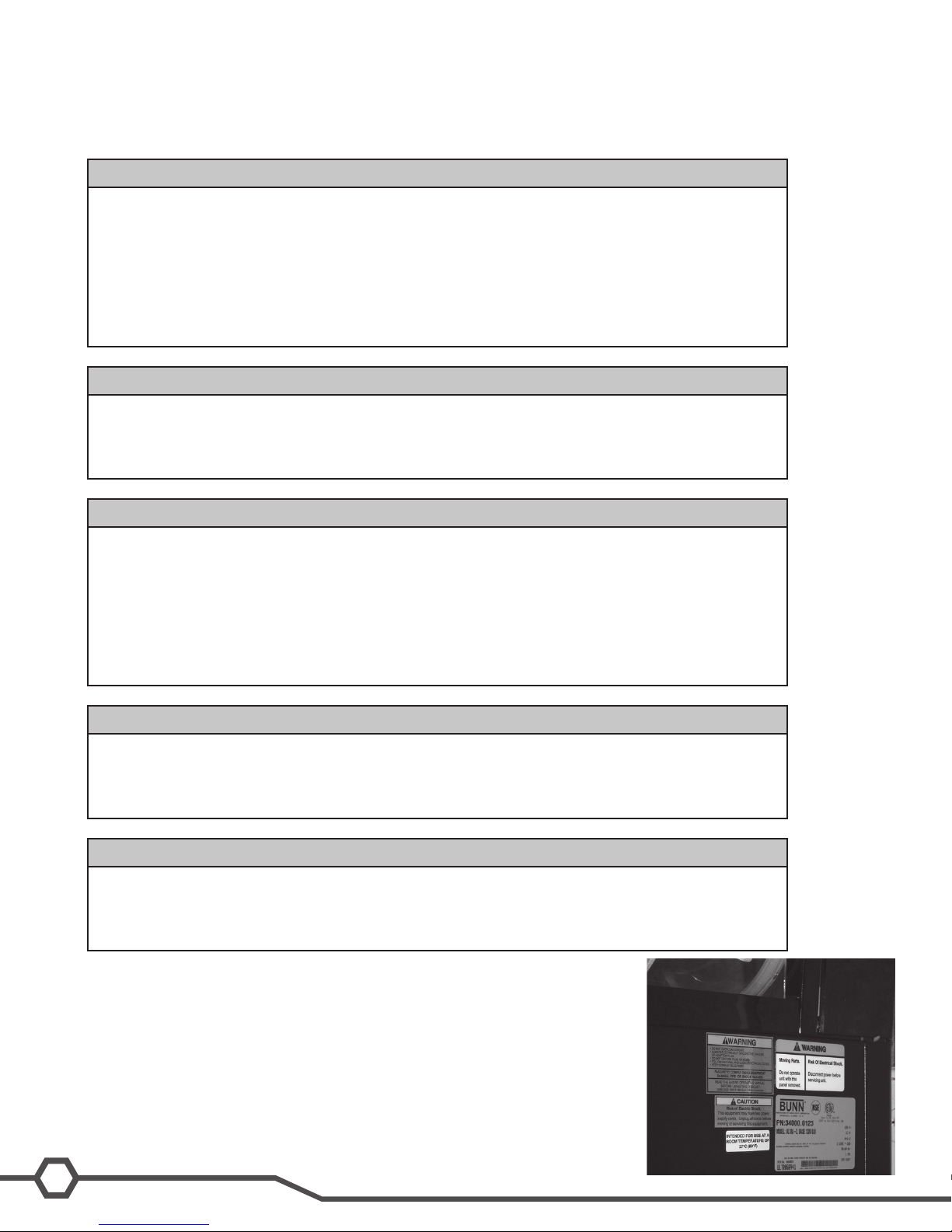
Location of the Serial Number
The machine’s serial number is located on the data plate, which is located on
the right side panel. The serial number half tag can be found on the inside of the
machine on the main machine frame.
4
Ultra Training Manual
Page 5
Prepping Machine for Install
Step 3: Place the machine in the desired location on the counter. Do not lift the Ultra by the drum(s).
Step 4: Document the complete serial number of the machine.
Step 5: Remove and save the black plastic drum support(s). This will be used as a servicing jig later.
Step 6: Adjust the legs on the machine so that it is level or slightly lower in the front.
Step 7: Remove the shipping eye bolts, located on the bottom of the machine, from the compressor.
Step 1: Verify that all of the site requirements have been met.
Step 2: Unbox the machine and all the parts.
Step 3: Place the machine in the desired location on the counter. Do not lift the Ultra by the drum(s).
Step 4: Document the complete serial number of the machine.
Step 5: Remove and save the black plastic drum support(s). This will be used as a servicing jig later.
Step 6: Adjust the legs on the machine so that it is level or slightly lower in the front.
Step 7: Remove the shipping eye bolts, located on the bottom of the machine, from the compressor.
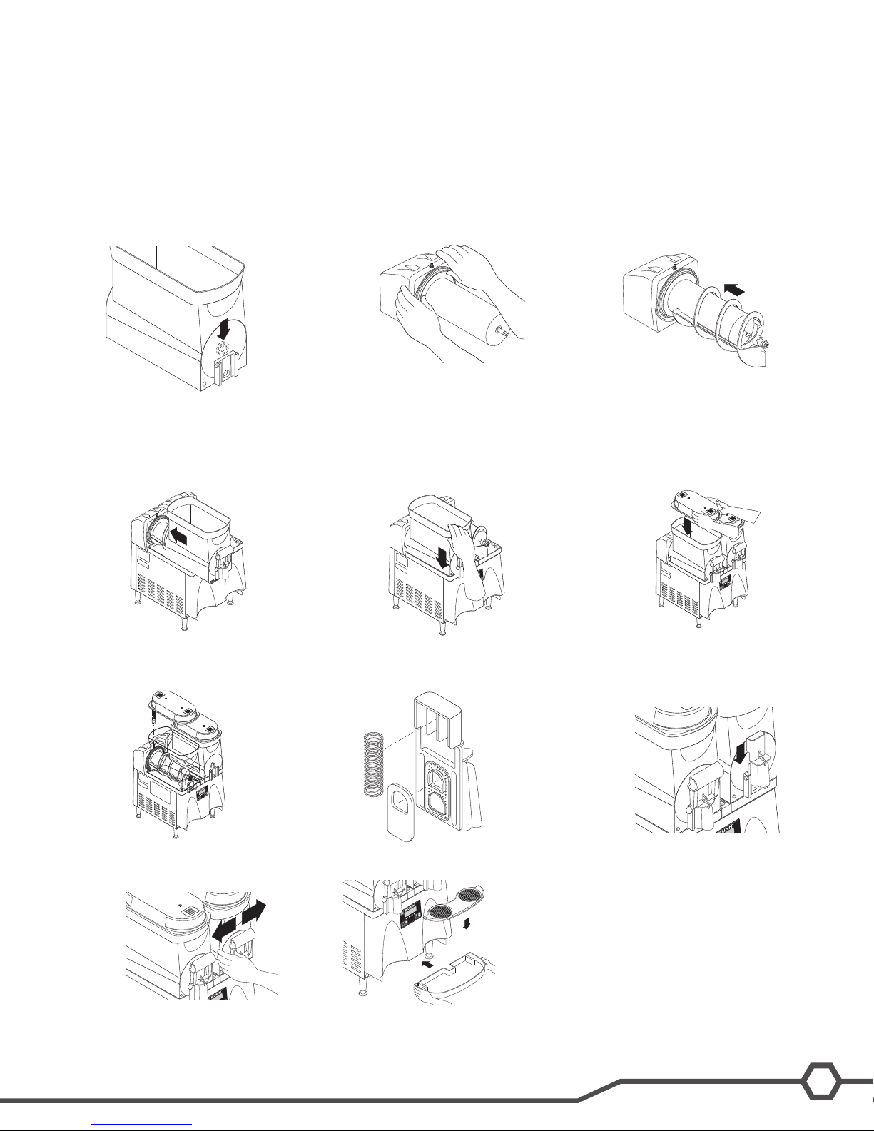
Hopper Assembly
Step 1: Insert the auger nose
bushing from inside the hopper.
Step 4: Install the hopper over the
auger and cooling drum and slide it into
place.
Step 2: Install the seal(s) over the
ange at the rear of the cooling drum(s)
and press the seal(s) rmly into place
as shown.
Step 5: Push down until the hopper
lock plunger snaps into place.
Step 3: Align the auger shaft(s) with
the auger(s). Push the auger(s) as far
as they will go and rotate so the at face
of the auger shaft is aligned with the at
face of the auger nose.
Step 6: Set the hopper lid on the hopper with lamp cord at the back.
Step 7: Plug in the hopper lid lamp
cord.
Step 10: Press down on the valve to
compress the spring. Position the faucet
handle over the faucet valve one side
at a time and snap into place on the
hopper.
Step 8: Position the faucet seal and
the return spring in the faucet valve.
Step 11: Install the drip tray and cover.
Step 9: Slide the faucet valve assem-
bly into place on the hopper.
5
Bunn-O-Matic Corporation
Page 6
Electrical Install
place.
Step 2: Place PAF platform assembly
on top of the motor covers and install
support rod into hole in trim strip.
Step 3: Tighten support rod from top of
platform. Retighten motor cover screws.
Step 6: Press the seals rmly into
place.
Step 8: Install the auger nose bushing
into the front of hopper.
Step 9: Thoroughly rinse the hoppers
and install them over the augers and
cooling drums.
Step 11: Install level probes into slots
at top rear of PAF hoppers.
Step 12: Install PAF unit onto platform
and plug power cord into rear of
platform. Plug platform power cord into
proper outlet.
Step 13: Assemble the drip tray.
Step 3: Tighten support rod from top of
platform. Retighten motor cover screws.
Step 6: Press the seals rmly into
place.
Step 9: Thoroughly rinse the hoppers
and install them over the augers and
cooling drums.
Step 12: Install PAF unit onto platform
and plug power cord into rear of
platform. Plug platform power cord into
proper outlet.
Step 1: Plug machine into 120VAC outlet.
Powder Autoll (PAF) Installation (Optional)
Step 1: Remove the rear plastic
plug from trim strip between the
hopper drip trays and loosen the
auger motor cover screws.
Step 4: Plug RCA cord into Ultra
base unit.
Step 7: Align the auger shaft with
the n of the auger. Push the
augers as far as they will go and ro-
tate them so the at n is facing up.
Step 2: Place PAF platform assembly
on top of the motor covers and install
support rod into hole in trim strip.
Step 5: Install each hopper seal over the ange
at the rear of the cooling drums as shown.
Step 8: Install the auger nose bushing
into the front of hopper.
Step 3: Tighten support rod from top of
platform. Retighten motor cover screws.
Step 6: Press the seals rmly into
place.
Step 9: Thoroughly rinse the hoppers
and install them over the augers and
cooling drums.
Step 10: Slide the hopper(s) into
place and push down until the
hopper lock plunger snaps into
6
Ultra Training Manual
Step 11: Install level probes into slots
at top rear of PAF hoppers.
Step 12: Install PAF unit onto platform
and plug power cord into rear of
platform. Plug platform power cord into
proper outlet.
Page 7
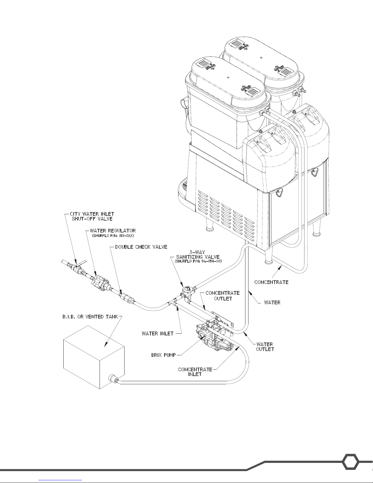
Liquid Autoll (LAF) Installation (Optional)
(50 PSI RECOMMENDED)
*
* Should be located no more
than 6” from pump.
The Brix pump should be placed as close to the concentrate supply as possible.•
The Brix pump mounting placement should be the same level or slightly higher than the concentrate BIB.•
Ease of access to the brix pump and sanitize valve for sanitizing procedure.•
7
Bunn-O-Matic Corporation
Page 8
Installing Liquid Autoll Kits (Autoll ready Ultra-2)
ULTRA-2
INSTRUCTIONS FOR INSTALLING
LIQUID AUTOFILL KITS
INTRODUCTION
These instructions are for installing the Liquid Autofill Kits on Autofill ready ULTRA-2 cold drink dispensers.
There are three different kits available:
INSTRUCTIONS (Continued)
37960.0000 ULTRA-2 Liquid Autofill Kit 120V with Separate Water Lines
37960.0001 ULTRA-2 Liquid Autofill Kit 120V without Water Lines
37960.0002 ULTRA-2 Liquid Autofill Kit 230V with Separate Water Lines
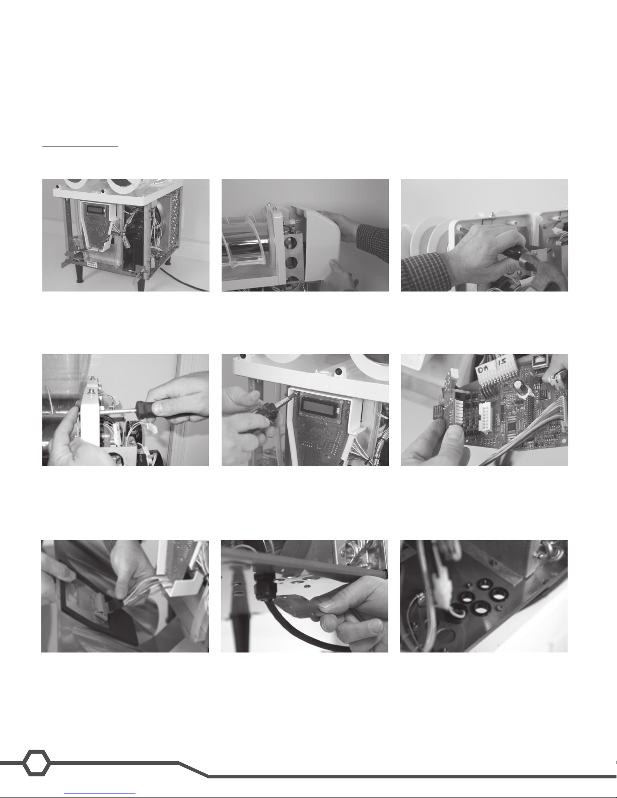
INSTRUCTIONS
1. Unplug machine from power source before removing any panels.
2. Drain both hoppers and clean the machine if needed before proceeding.
3. Remove hoppers, drip tray, both side
panels and front panel.
4. Remove both motor covers and locate
.50” round knock out in top right area
of plastic drum mount.
5. With a standard screwdriver and a
hammer, punch out the hole needed
for the level probe. Repeat this step
for both sides.
6. Install level probe assembly into hole
and secure with nut provided.
9. Reinstall the main board into the
machine using the original mounting
screws.
8
Ultra Training Manual
7. Remove 4 screws holding in the main
circuit board.
10. Remove hole covers from the base of
the machine as needed to route water
and product tubing through base.
8. Connect Auto Fill board to main board.
Be sure to snap the plastic stand off’s
completely into the main board.
11. Install provided bushings into product/
water holes to protect the tubing.
Page 9
INSTRUCTIONS (Continued)
11. Install provided bushings into product/
water holes to protect the tubing.
10. Remove hole covers from the base of
the machine as needed to route water
and product tubing through base.
9. Reinstall the main board into the
machine using the original mounting
screws.
INSTRUCTIONS (Continued)
skip to step 24 through 26.
Early Models
INSTRUCTIONS (Continued)
14. Install valve and bracket assembly by
feeding the attached tubing through
the smaller snap bushings in the base
of the machine.
13. Remove top nut off of grounding stud
in the base of the machine, add on the
green grounding wire from the new har-
ness and reinstall the nut onto the stud.
Make sure that all the other grounding
wires remain on the ground stud.
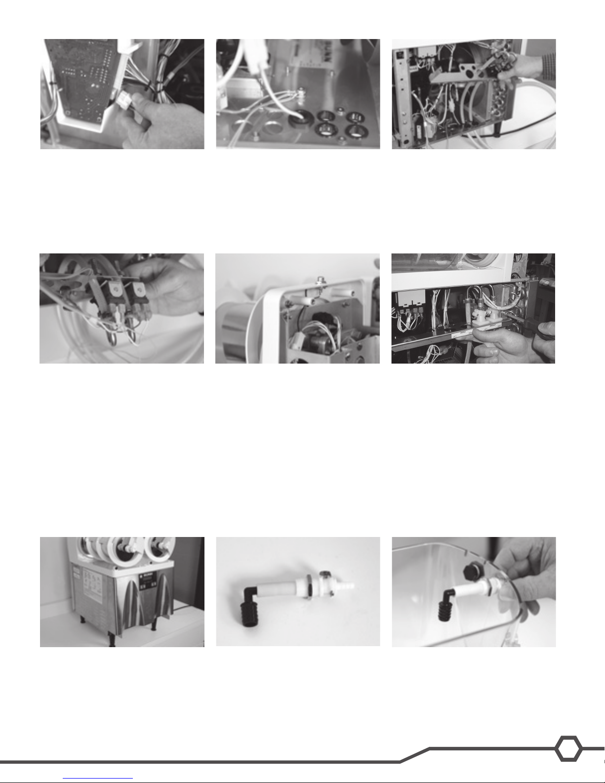
12. Plug wire harness (supplied with kit)
into Auto Fill board connector and route
wires back into the machine.
11. Install provided bushings into product/
water holes to protect the tubing.
10. Remove hole covers from the base of
the machine as needed to route water
and product tubing through base.
9. Reinstall the main board into the
machine using the original mounting
screws.
12. Plug wire harness (supplied with kit)
into Auto Fill board connector and route
wires back into the machine.
15. Connect the wires to the fill valves both
water and product as needed according
to the wiring schematic provided. Red
and White wires to the right valve(s),
Blue and white wires to the left valve(s).
Please note that Left and Right are from
the front of the machine, Users left and
right.
13. Remove top nut off of grounding stud
in the base of the machine, add on the
green grounding wire from the new harness and reinstall the nut onto the stud.
Make sure that all the other grounding
wires remain on the ground stud.
16. Route Pink and Tan wires up to level
probes and attach using nuts provided.
Pink is the right probe and Tan is the
left probe.
14. Install valve and bracket assembly by
feeding the attached tubing through
the smaller snap bushings in the base
of the machine.
17. Position the valve and bracket assembly
between the right front corner post and
the right side fan shroud and secure
with screws provided.
Early Models
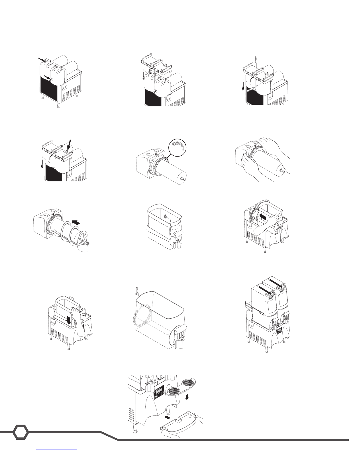
18. Reinstall front panel, left panel and both
motor covers.
Early models with quick disconnect fittings,
follow steps 19 through 23.
Late models with new hopper slide fitting
19. Assemble a .25” quick disconnect fitting, 1.25” neoprene tube and barbed
elbow as shown with the .50” barb
pointing down.
20. Remove one or both plugs from the hop per depending on whether a separate
water line is being installed. Install the
quick disconnect fitting into the hole on
the hopper and secure with nut provided
with fitting.
9
Bunn-O-Matic Corporation
Page 10
INSTRUCTIONS (Continued)
20. Remove one or both plugs from the hop -
per depending on whether a separate
water line is being installed. Install the
quick disconnect fitting into the hole on
the hopper and secure with nut provided
with fitting.
19. Assemble a .25” quick disconnect fit-
ting, 1.25” neoprene tube and barbed
elbow as shown with the .50” barb
pointing down.
18. Reinstall front panel, left panel and both
motor covers.
Early models with quick disconnect fittings,
follow steps 19 through 23.
Late models with new hopper slide fitting
skip to step 24 through 26.
Early Models
INSTRUCTIONS (Continued)
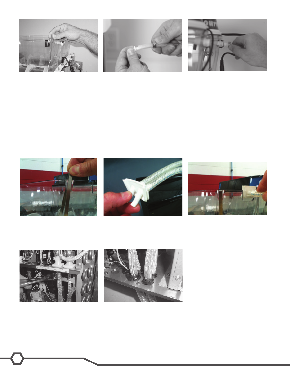
21. Install hoppers onto machine and
slide probes onto hoppers into slots
provided.
Late Models
22. Route the tubes from the solenoids up
to the quick disconnect fittings on the
hoppers. The tubes are supplied with
extra length to allow for trimming if
desired. Slip a clamp over the end of
the tube and install a .25” male disconnect fitting. Position the clamp over the
barb area of the fitting and crimp into
place.
NOTE: Make certain the tubes are routed
to the correct hoppers to prevent product
from being mixed or hoppers overflowing.
23. Connect the tubes to the hoppers.
24. Install hoppers onto machine and
slide probes onto hoppers into slots
provided.
27. Install customer supplied pump system.
Turn on pump system and water supply.
Check all tubing connections for leaks.
25. Route the tubes from the solenoids
together and connect to hopper fitting.
28. Install snap clamps on to hoses just
above the bushings to prevent hoses
from being pulled loose from the solenoid valves.
26. Slide hopper fitting into place in the
slot on the hopper.
10
Ultra Training Manual
Page 11

29. Apply power to machine and turn water on for Brix Pump operation. Refer to the Programming section of this manual in the Refill
INSTRUCTIONS (Continued)
27. Install customer supplied pump system.
Turn on pump system and water supply.
Check all tubing connections for leaks.
28. Install snap clamps on to hoses just
above the bushings to prevent hoses
from being pulled loose from the so-
lenoid valves.
Threshold section to check refill for proper operation.
30. At the threshold screen, with no product in the hopper, confirm the number on the left (top) of the screen is around 250. The
number on the right of the screen is factory set to 155. The factory set point should not need any adjustment.
31. After confirming that both hoppers are reading about 250 for the threshold, proceed to the next screen to test the refill circuit.
32. At the test refill screen, select yes.
33. The Activate Valve screen will allow you to test the pumping and refill circuit. Press and hold the ULTRA button to activate the left
refill system. Confirm that the left side is filling when the ULTRA button is pressed. Release the ULTRA button to stop the filling
process. Repeat this process for the right side by pressing the ICE button to test. Check for leaks at the hoses while pumping
system is running.
34. Once the testing is complete, exit the programming menu and reinstall the right side panel.
35. The auto fill feature can be turned on by pressing the auger button for each side until the display reads “AUGER REFILL ON”.
NOTE: Some models also include a “Delay Refill” option. This feature is used to dose in small amounts of new product while delaying
between doses. This can help the already frozen product from becoming deluted and not ready to serve. These delay and fill times are
to be determined and set based on each application as desired by the end user.
11
Bunn-O-Matic Corporation
Page 12

Unit 2 setup
Unit Objectives
Given a realistic scenario depicting a new site install, the learner will be able to install and setup the ULTRA for
customer turnover without error.
Given an installed machine, all the necessary tools and safety equipment, the learner will be able to set the
machine up for initial operation.
The learner will be able to operate the switch controls.
The learner will be able to enter and navigate programming.
The learner will be able to understand and perform the task of setting priority menus.
The learner will be able to perform product preparation and adjustments of the optional accessories
(PAF & laF).
Page 13
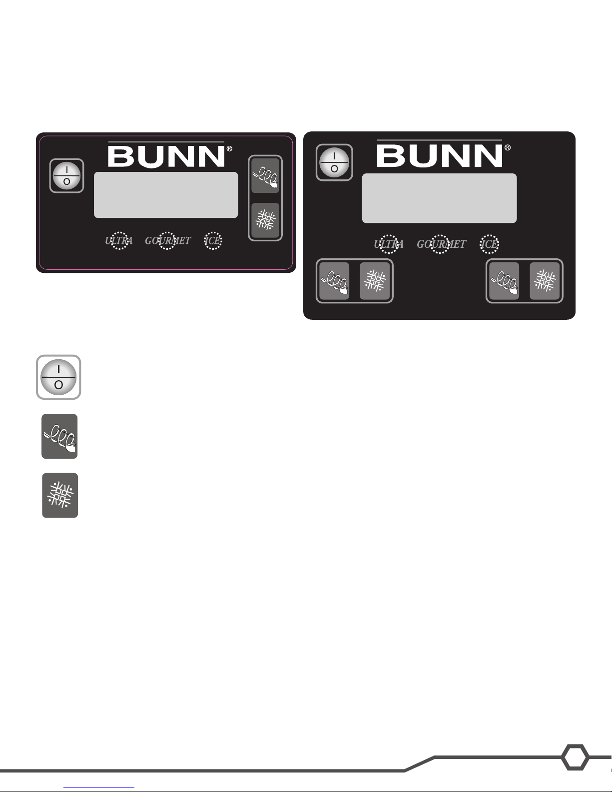
User Interface
Using the menu-driven display on the front of the dispenser, the operator has the ability to operate, alter or modify
various parameters such as beverage consistency and set day/night “ON/OFF” times. The operator is also prompted
to check a variety of periodic service functions or even a step-by-step cleaning routine.
Operating Controls
This switch is the ON/OFF toggle switch which powers up the dispenser and the LCD display. This switch
is also used as back up switch in menu mode.
Ultra 1
Ultra 2
Press and release the appropriate (ON/OFF) switch to start the Auger Motor and to turn on AutoFill when
applicable.
Press and release the (OFF/ICE/CHILL) switch and select CHILL to begin the cooling process for the
selected hopper.
Programming Controls
To access the programming mode, and to scroll through the different function screens, hidden programming switches
are used. Press and hold for ve seconds the “Gourmet” button to enter into the programming menus.
“ULTRA” (left under display)
When prompted by a selection from the menu to answer yes or no, the “ULTRA” switch is used to answer
“NO” or (-) minus.
“GOURMET” (center under display)
Press and hold this switch 5 seconds to access the Menu Function Index. This switch is also used as “NEXT”
to scroll through the functions.
“ICE” (right under display)
When prompted by a selection from the menu to answer yes or no, the “ICE” switch is used to answer “YES”
or (+) plus.
13
Bunn-O-Matic Corporation
Page 14
Setup
Setup Machine
The following machine parameters should be set upon placement of machine for product turn over.
□ Set Thickness (Product consistency)
□ Set Date Time
□ Set Language
□ Set Night Time
□ 6 Month PM (Recommended)
□ Day To Clean (Recommended)
LAF Set Up Menus
□ Delayed Rell
□ Enable Rell ? (Ultra-1 Only)
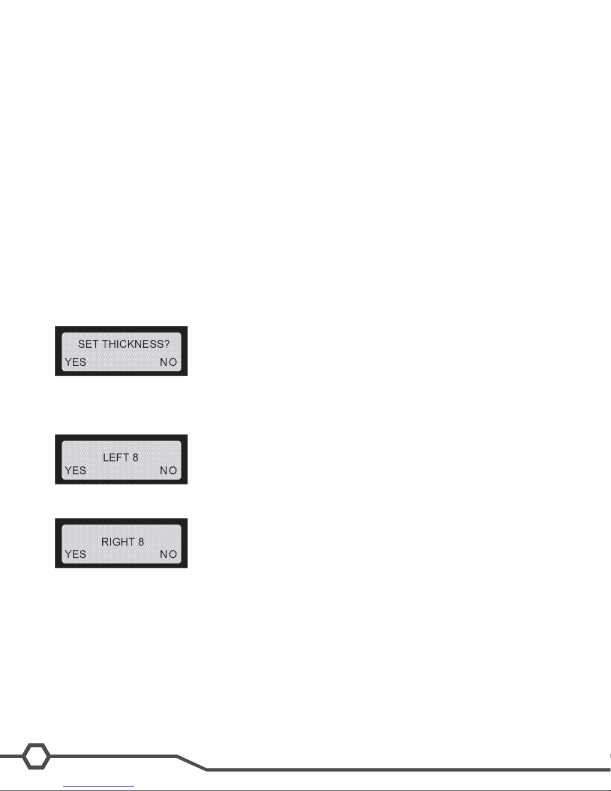
Set Thickness
Setting the thickness changes the ice consistency, or torque of each auger. The factory default is 8 with a range of 1
to 16.
Step 1: Press and hold the Gourmet switch until the display screen reads “Cleaning Guide?”.
Step 2: press and release the Gourmet switch until the “Set Thickness?” option is shown in the display screen.
Step 3: Select Yes (Ice) to access the Set Thickness option.
Step 4: Use Min (-) and Max (+) to adjust the thickness levels. Press the Gourmet switch to accept the desired set-
ting for the left side.
Step 5: Use the same controls to adjust the thickness level for the right side. Press the Gourmet switch to accept the
desired setting.
Step 6: Press Next (Gourmet) until you exit programming and return to the Home Screen.
Set Date Time
Allows the operator to set the DATE (YY MM DD) and TIME (HR MIN SEC) for display on the Home Screen.
Step 1: Press and hold the Gourmet switch until the display screen reads “Cleaning Guide?”.
Step 2: Press and release the Gourmet switch until the “Date/Time” setting option appears in the display screen.
14
Ultra Training Manual
Page 15

Step 3: Select Yes (Ice) to access the set Date/Time option.
Step 4: Use Min (-) and Max (+) to adjust the setting to the appropriate year. Select Next (Gourmet) to continue.
Step 5: Use Min (-) and Max (+) to adjust the setting to the appropriate month. Select Next to continue
Step 6: Use Min (-) and Max (+) to adjust the setting to the appropriate day. Select Next to continue.
Step 7: Use Min (-) and Max (+) to adjust the setting to the appropriate hour. Select Next to continue.
Step 8: Use Min (-) and Max (+) to adjust the setting to the appropriate minute. Select Next to continue.
Step 9: Use Min (-) and Max (+) to adjust the setting to the appropriate second. Select Next to continue.
Step 10: If you are satised with the changes, keep pressing Next (Gourmet) until you exit programming and return
to the Home Screen.
Set Language
The setting of the Set Language mode allows the operator to scroll thru a list of languages stored in the software and
select one for the display messages.
Set Night Time
The setting of the Day/Night mode allows the dispenser to “power down” during off hours. The bottom corners displaying “ICE” will change to “CHILL” during the night mode. During the night mode, the product will be kept chilled to
below 35°F. “ICE” reading will return after night mode elapses. With “OFF” representing 12:00 AM, the operator can
scroll to the times desired for the night time mode to begin and end.
15
Bunn-O-Matic Corporation
Page 16

Step 1: Press and hold the Gourmet switch until the display screen reads “Cleaning Guide?”.
Step 2: Press and release the Gourmet switch until the “Set Night Time” setting option appears in the display screen.
Step 3: Use Min (-) and Max (+) to adjust the setting to the desired time. When nished, Press and release the Gour-
met switch and proceed to Day Time setting.
Step 4: Use Min (-) and Max (+) to adjust the setting to the desired time. When nished, keep pressing Next (Gour-
met) until you exit programming and return to the Home Screen.
6 Month PM
This function is used to set a reminder message Preventive Maintenance Due every six months. The machine will
not shut down if service is not performed. When the service is performed and the message, “PM COMPLETE?”, is
answered “YES” (ICE), the time and date is recorded for another six months to elapse.
Step 1: Press and hold the Gourmet switch until the display screen reads “Cleaning Guide?”.
Step 2: Press and release the Gourmet switch until the “6 Month PM” setting option appears in the display screen.
Step 3: Use Min (-) or Max (+) to turn this function on/off. If you are satised with the changes, keep pressing Next
(Gourmet) until you exit programming and return to the Home Screen.
Day To Clean
This function allows the operator to program a cleaning schedule from 1 to 14 days.
Delayed Rell
This function allows the operator to dose in small amounts of new product while delaying between doses.
This can help the already frozen product from becoming diluted and not ready to serve. These delay and ll times are
to be determined and set based on each application as desired by the end user.
Enable Rell (Ultra-1 Only)
This function will activate the Liquid Autoll function only in machines equipped with the LAF option.
16
Ultra Training Manual
Page 17

Product Preparation
Whether liquid concentrate or granulated powder, all product must be thoroughly mixed BEFORE adding it to the
hoppers.
For best results with granita-type products, use only products with an apparent brix of 12 or higher. Some products
may work with an apparent brix as low as 9. Your experimentation with other products will be the best guide in this
area.
Keep the pre-mixed liquid product refrigerated. This reduces cooling/freezing time in the dispenser.
Keep the hoppers topped-off during peak serving periods. Add pre-mixed liquid product as it is dispensed. This reduces the cooling/freezing time and assures you of always having product ready to dispense.
Keep the product level in the hoppers higher than the auger. If the auger is exposed, air will become entrapped in the
mixture resulting in a clouded foamy consistency.
You may nd it benecial to turn down the ice controls to keep the ice granules from growing too large.
Some products freeze at a lower temperature than others. You may notice frost or ice on the hoppers. This is normal
and should not be a concern.
Humidity in the air may cause sweating on the outside surfaces of the hoppers. This is to be expected and should
not be a concern. The drip trays beneath the hoppers will capture this and cause it to ow to the lower drip tray for
disposal.
Some noises are to be expected during normal operation of the dispenser. By becoming familiar with the noises
made during normal operation, you will be better able to listen for problems.
PAF- Powder Mix Set-Up (Brix Ratio)
When using the PAF with a new powdered granita mix, follow the procedure outlined below to adjust the PAF to produce the correct brix ratio according to the product manufacture.
Step 1: Determine the mix ratio of powdered granita mix. Convert the recipe so that it is expressed in terms of weight
units [grams (g), dry ounces (oz), or pounds (lbs)] of powdered granita mix to uid ounces (.oz.) of water [1 gallon
gal) = 128 .oz.; 1 liter (l)= 33.8 .oz.].
Step 2: The delivery rate of the water ingredient is factory preset to 1 .oz. per second. Therefore, it is only necessary
to adjust the delivery rate of the powdered granita mix.
Step 3: Place the PAF on top of a fully assembled ULTRA taking care to align the PAF guide rails over the rollers on
the platform guide rails.
Step 4: Connect the PAF power cord to the outlet located on the ULTRA auger motor cover.
Step 5: Attach a exible water line to the .25” are tting on the back panel of the PAF.
Step 6: Ensure the ULTRA is powered ON and the Day/Night setting is set to Day.
Step 7: Pull the PAF fully forward on its support rails.
17
Bunn-O-Matic Corporation
Page 18

Step 8: Pull the slide gate closed on the PAF product hopper elbow and remove the product hopper from the PAF.
Step 9: Remove the lid from the product hopper and ll the hopper with a powdered granita mix.
Step 10: Install the product hopper into the PAF.
Step 11: Place the ON/OFF switch at the PAF whipper panel to ON.
Step 12: After allowing 5 seconds for the PAF to initialize, observe the door lamp on the whipper panel. The door
lamp should not be lit. If the door lamp is lit, consult the fault list and clear the fault before proceeding.
Step 13: Remove the hole plug on the whipper panel. Using a slotted screwdriver, set potentiometer to approximately mid range.
Step 14: Remove the mixing chamber from the PAF and place a small container, such as a cup, under the product
hopper ejector elbow.
Step 15: Push the slide gate on the product hopper ejector elbow to the OPEN position.
Step 16: Momentarily set the TEST/SERVICE switch on the whipper panel to the TEST position. The hopper motor
will run and dispense powdered granita mix for 10 seconds.
Step 17: After the PAF has nished the 10 second throw test, weigh the dispensed product.
Step 18: Determine the dispense rate of the powdered product (weight units per second) by dividing the measured
weight by 10.
Step 19: Compare the measured dispense rate with the mix ratio in
Step 1. Adjust the MIN/MAX control clockwise to increase the dispense
rate or counterclockwise to decrease the dispense rate of the
powdered granita mix. Repeat Steps 16 through 19 as necessary
until proper mix ratio is achieved.
Step 20: Once the mix ratio has been adjusted, the PAF can be run
with the door open. This will allow you to catch dispensed product for
brix testing.
Step 21: Hold a container under the dispense tip of the PAF.
Step 22: Hold the TEST/SERVICE switch on the whipper panel to the
SERVICE position.
Step 23: When the container is lled to the desired level, release the
TEST/SERVICE switch.
Step 24: Measure the brix using the appropriate measuring device.
Step 25: Remove the hole plug. Using a slotted screwdriver, adjust
the potentiometer clockwise to increase the brix or counterclockwise
to decrease the brix of the product. Replace the hole plug.
Adjustment for Powder Throw Weight
LAF – Liquid Concentrate Set-Up (Brix Ratio)
The SHURo BRIX proportioning pump is driven by pressurized water, allowing the water and product to be delivered
at an exact ratio. The pump operates whenever there is a differential in pressure between the inlet and outlet water
sides of the pump.
Step 1: Purge water lter if applicable and conrm all water devices are properly placed, tubing connections are
properly clamped and lines are not kinked.
Step 2: Install the BIB connector onto the receiving product container.
Step 3: Locate concentrate and water tube that will connect to the quick disconnect ttings on the hopper, place
water
and concentrate tube inside of an empty container to prime the concentrate and the purging of air out of the lines.
Step 4: Check 3 –way sanitize valve for dispense position and slowly turn on the main water supply.
Step 5: Allow the pump enough time to purge all the air out of the lines and check for desired ow rate of product
and water. Adjust pressure regulator if applicable or adjust water shut off
valve if using a xed water ow regulator. When the desired ow rate is
achieved, turn off the water supply.
Step 6: See hopper assembly instruction sheet. Install level probe onto
the hopper.
Step 7: Connect the tubes to the hopper quick connect connectors. Keeping
the water and concentrate line accordingly to the correct hopper on a
two hopper machine.
Step 8: Turn on the water supply and the machine is now ready for start
up and initial ll of the hopper.
18
Ultra Training Manual
Page 19

ULTRA 1 and 2 Start Up with LAF
Step 1: Review the switch operation of the user panel.
Step 2: Apply power to the machine.
Step 3: Press and release the (ON/OFF) switch to power on the machine.
Step 4: ULTRA with LAF option: Press and release the appropriate (ON/OFF) auger switch until the appropriate
“Auger Rell On” mode is selected. This mode activates the motor and rell circuit in unison and will automatically
maintain the level of product in the hopper to the probe level.
Note: ULTRA-1 only – Enable the rell menu in the programming to activate the
liquid autoll function.
Step 5: Press and release the (OFF/ICE/CHILL) switch until the appropriate
mode is selected (ICE).
Step 6: The cooling process is now activated and cooling will begin after a
sequence delay within the start up or activation of the cooling system.
Ultra 1 Only (Step 4)
19
Bunn-O-Matic Corporation
Page 20

Unit 3 Machine coMposition
Unit Objectives
Given a realistic scenario in which the learner has access to the machine’s internal components the learner will understand the composition and functions of the machine.
Given a realistic scenario requiring the learner to access the internal components of the machine the learner
will be able to remove the top motor covers, side panels and front control panel.
Given an operating machine the learner will be able to give a general explanation of how the machine
operates.
The learner will be able to identify the components and functions of the mechanical system.
The learner will be able to identify the components and functions of the refrigeration system.
The learner will be able to identify the component and function of the temperature sensing systems.
The learner will be able to identify the components and functions of the remaining components not
comprised in the identied systems.
Page 21

Machine Composition
Exterior Overview
Hopper Lid
Hopper
Product outlets and removable parts
• Hopper outlet(s)
• Drip tray
• Hopper(s)
• Auger(s)
• Faucet(s)
• Hopper lid(s)
• Air lter
Auger
Air Filter
(on back)
Removing the Enclosure
The majority of the service work done to the ULTRA will require the service technician to access the inside of the
machine. The ULTRA enclosure is comprised of two side panels, front control panel and two top motor covers to
facilitate access to the refrigeration and electrical components.
Depending on the repair the technician may have to remove one or all of these panels. In order to work safely the
power should be disconnected prior to removal of any body panel. Once the panels and drip tray are removed, the
power can be reconnected in order to troubleshoot the machine.
Facuet
Drip Tray
Front Control Panel
Removing the front control panel will give you access to the main control board, Tic board, switch membrane ribbon
connection and hopper drip tray drain tubes.
How to Remove
The control panel is attached to the main housing by 1 hex slotted and 2 standard slotted screws.
21
Bunn-O-Matic Corporation
Page 22

The left and right side panel will need to be removed rst to give access to the single standard slotted screw on each
side. One ¼ inch hex slotted screw is located in the front support bracket located in front center behind the drip tray.
TIC board
TIC board
Control board
Control board
front control panel is now ready for nal removal by pulling downward and away from the machine. Be cautious
upon removing the panel because of the switch membrane connection.
The
Left Side Panel
Removing the left side panel will give you access to the refrigerant solenoids, hot gas sensor/thermistor and optional
LAF water valve/ULTRA-1 only.
How to Remove
The left side panel is attached by 2, 1/4 inch hex slotted screws on the underside. Remove or loosen the screws and
the panel is now ready for removal by pulling downward and out.
Hot Gas Sensor Solenoids
22
Ultra Training Manual
Page 23

Right Side Panel
Removing the right side panel will give you
access to the hood light relay, lamp circuit
breaker, compressor relay, stepdown transformer, condenser fan/ULTRA-2, compressor
starting components and optional LAF water
valve/ULTRA-2 only.
How to Remove
The right side panel is attached by 2, ¼ inch
hex slotted screws on the underside. Remove or loosen the screws and the panel is
now ready for removal by pulling downward
and out.
Top Motor Covers
Removing the top motor cover per side will give you access to the auger motor, start/run capacitor, torque sensor
board, evaporator thermistor and auger shaft assembly plus bushing and seal.
How to Remove
The motor cover is attached by 2 slotted standard screws in the rear per side. Remove the screws and the motor
cover is now ready for removal by pulling backwards.
23
Bunn-O-Matic Corporation
Page 24

Compressor
Electrtic Motor Type: The type of motor being used in the ULTRA-2 HP dispenser is known as CSR motor (Capacitive
Start & Run).
The CSR version uses a start and run capacitor with an external thermal protector. The start capacitor is in series
with the compressor motor start winding. A potential starting relay coil is wired across the start winding which can
sense change in voltage. The starting winding voltage will increase along with motor speed. When the voltage has
reached a point, the relay contacts will open, de-energizing the start winding capacitor.
Capacitor Ratings:
Start Capacitor: 243-292 MFD 165V 50/60HZ
Run Capacitor: 35 +/-5% MFD 425V 50/60HZ
Refrigerant Charge:
Type: R404A
Amount: 11 oz.
Design Pressure: High 430 & Low 80
24
Ultra Training Manual
Page 25

LED & CORD ASSEMBLY
The LED board input voltage requirement is 12.6 volts a/c with a LED life expectancy of 5 years or more. A number of
led’s are surface mounted on the boards which illuminate white in color to light up the graphic display.
Machine Function and Operations
Addition of Clock and Battery to Circuit Board (44039.1000)
The clock and battery back up is now incorporated into the 44039.0000 control board. The dispenser will no longer
store or display the serial number of the machine. An instruction sheet has been created to dene the changes when
performing eld replacement of the old control board with the new control board (47698.0000B).
• The install date feature is still active. Install date is now referencing the installation of the circuit board instead of
the machine. After running for about four days, the software will set a new install date into the memory to
reference the circuit board replacement.
• If the new 44039.1000 circuit board is installed in a machine that already has a TIC circuit board, the installer can
choose to connect the old TIC to the new circuit board. When connected, the software will pull the customer
specic settings from the TIC only once. Afterwards, it will never reference the TIC again.
• The user settings will need to be recorded before the removal of the old control board if your not going to connect
the old clock/memory board to the new control board (44039.1000).
User Setting List to be Recorded:
Thickness setting L = R =
Password =
Night time =
Day time =
3 Volt Battery
Defrost minutes =
Freeze minutes =
6 month PM = on/off
Days to Clean =
Thick Adjust = yes/no
Switches = on/lockout
Delay Rell = on/off
Rell time =
Delay time =
Ad Message = enabled/disabled
Enter asset # = (If applicable)
Main Control Board
25
Bunn-O-Matic Corporation
Page 26

The main control is the brain of the machine. The control board is the single component that contains all of the
programming software, it interprets all the data it receives from the level probe (LAF & PAF), temperature sensors,
switch inputs and torque monitor/sensor board. The input data received will command accordingly to turn on the outputs to maintain a cold or ice product in the hopper.
Mechanical System
The mechanical system mixes the product, shaves the product from the cooling drum and pushes the product forward during dispensing mode. The product mixing and dispensing occurs as the auger motor rotates the auger. The
auger will stop and run counterclockwise for 2 minutes on the hour or during a certain sequence that takes place with
time and temperature of the product.
The thickness of the product is measured with a torque sensing system. This system utilizes two pins, one located on
the auger shaft and one located on the auger motor shaft. The auger shaft is connected to the auger motor shaft via
torsion springs, which allow the two pins to separate under torque. The distance between the pins is measured with a
torque sensing board that emits a light beam every time the beam is broken by the pin on the auger motor. A signal is
sent (voltage) to the main control board. The main control board processes this information and energizes/de energizes the refrigeration system as needed to keep the product thickness consistent. The dispense system or faucets
are manually operated by pulling down on the faucet handle until cup is full then release handle.
Refrigeration System
The cooling system for the Ultra is designed to make a frozen slush. This is accomplished through the use of a
torque monitored refrigeration system. Upon initial startup of the machine, the compressor and fan will turn on after
a delay. The amount of time for the delay is based on the cooling drum temperature. For instance, if the thermistors
sense that both barrels, (one for Ultra-1), are above 50º F when the machine is powered up, the delay time is 1 minute. If any of the barrels are below 50º F, then the delay time is 6 minutes. Once the compressor and fan are operational the removal of heat from the product begins, cooling the product to programmed consistency.
New control bard (44039.1000) will run the condenser fan for a 2 minute On and 10 minute Off cycle anytime the
power is on and it’s not running for refrigeration purposes.
The thickness, (consistency), is set within the program menu and can range from 1 to 16. The thickness setting is
3 times the number, which is related to
torque. The programmed setting is the
operating parameter for the torque circuit,
which monitors the product thickness.
When the torque circuit determines
desired thickness is achieved the corresponding refrigerant valve is turned off
and the compressor remains on for 30
seconds. If during this time the processor
determines that cooling is still needed in
the
barrels, the valve will open and the compressor continues to run. When the torque
reading stays above the desired set point
for over 30 seconds, then the microprocessor will shut off the output to the
compressor relay coil, which turns off the
compressor. The condenser fan runs for
an additional minute after the compressor
has shut down. Once the compressor has
shut down it requires a 6 minute delay
before it can restart.
The system will determine if cooling is
needed based on the torque reading.
Software has some hysteresis pro-
26
Ultra Training Manual
Page 27

grammed into this setting, which is plus 1 and minus 4. This means the valve will turn off above 31 and will not come
SHAFT
SHAFT
SHAFT
back on until it drops below 26.
The actual setting the processor uses is 3 times what the user has set in the menu. For instance: if the setting is at
10, then the system will turn the refrigerant valve off at 30 plus 1 (hysteresis) and will not come back on until below
the minus 4 hysteresis from 30.
The new software brings approximately 3% reduction in energy usage by looking at both barrels instead of each
barrel independently. The new software looks at both barrels to determine when to turn on. If one barrel reaches the
minus 4 thickness setting which requires the refrigeration system to turn on, the control board will look at the second
barrel thickness number and will turn on the barrel to refrigerate if the number is equal or below the barrel thickness
setting before it actually passes the maximum number of minus 4 to activate barrel cooling process. By changing the
operation, the attempt is to reduce the cycling of the compressor which will reduce energy consumption.
Temperature Sensing System
The Ultra uses a thermistor to monitor the actual temperature
of each cooling drum. Night and Chill modes maintain 35º F,
instead of the torque sensing board (product thickness).
Torque Sensing
The torque springs within the auger shaft assembly will ex depending upon
the amount of torque applied to the torsion springs by the cooling of the product
which creates ice crystals. The ice crystals size relates to the size of the
gap created between the two pins (auger motor pin & auger shaft pin) .The “thickness” adjustment menu ranges from
1- 16 which sets the target gap between the pins.
Note: Product with high sugar content above 12 brix or alcohol will be a factor in longer freeze times. The product will
need to go much lower than 32º F. before it may or may not form ice crystals.
SHAFT
SHAFT
SET THICKNESS ?
NO YES
LEFT 9
RIGHT 5
27
Bunn-O-Matic Corporation
Page 28

Unit 4 preventive Maintenance
Unit Objectives
Given a realistic scenario depicting a machine requiring a preventive maintenance, the learner will be able to
identify which elements of a component need to be serviced without error.
Given a machine, all the necessary tools and safety equipment, the learner will be able to identify the
components that need to be serviced for the PM.
Page 29

Preventive Maintenance
In order to maintain proper operation and long service life BUNN recommends performing the preventive maintenance every 6 months. Some of the PM items may require more frequent maintenance depending on the site conditions and usage. Failure to perform these procedures may result in damaged equipment and may not be covered by
warranty.
Tools Required:
• Small & Medium standard blade screwdriver
• Medium philip screwdriver
• ¼ inch ratchet set
• Basic misc. size wrenches
• 2 Clean 5 gallon buckets
• Sponge
• Cloth or towel
• Extended bristle brush (PN: 40500.1068)
• Food grade lubricant (PN: M2550.0001 – 1 ounce Lubrilm)
• Krytox Grease (PN: 29563.0000 - .08818 oz. or M2548.1000 – Bulk oz.)
• Condenser Cleaner
• Rubber gloves
• Safety goggles or face shield
• Fin Comb
• Vacuum with brush attachment
• Mild non abrasive detergent
PM Parts
• ULTRA 1 PM Kit – PN: 34245.0002
• ULTRA 2 PM Kit – PN: 34245.0000
Prior to servicing the ULTRA:
• The ULTRA has an optional menu setting that may alert the operator when Preventive Maintenance is due by
displaying a message on the display, the message will read “Shaft Seal Maintenance Due”. The message will not
shut down the machine if the service is not performed. The technician will need to be aware to reset the menu by
answering “yes” in the “PM Complete ?” menu located in the programming section. Be aware that the menu might
be password protected. Once you answered the menu with “yes”,
the time and date is recorded for another six months to elapse.
• The ULTRA may have the optional LAF and PAF accessories
installed and will require turning off the main water supply.
• Unplug or disconnect ULTRA and/or PAF Platform from power.
• Drain hoppers of product into clean holding containers and ask
store manager to store product in a cooler or refrigerator.
• Remove hopper assemblies and ask store manager to perform the
necessary cleaning procedure of the hoppers while you perform
the preventive maintenance.
Preventive Maintenance Instructions
Step 1: Shaft Seal Maintenance ( PM Kit Required)
□ Drain, remove and clean hopper; refer to the Operating and
Service Manual for proper cleaning procedures. Discard the
hopper/drum seal and faucet seal.
□ Remove the #8 locking screws securing auger motor cover to the
cooling drum mount assembly; remove cover and set aside for
reassembly.
Figure 1
29
Bunn-O-Matic Corporation
Page 30

□ Remove the #8 locking screw on the lower right side (viewed from front) of the auger motor mounting bracket
securing the auger motor run capacitor. Set capacitor aside with wires attached.
□ Disconnect the auger motor terminal from the terminal on the main wiring harness.
□ Remove the remaining #8 locking screws securing the cooling drum mounting bracket. Remove motor with
mounting bracket.
Note: When removing or installing motor and shaft assemblies, be sure the split pins are turned to a position
that will clear the torque sensor circuit board.
□ Pull the auger shaft assembly straight out of cooling drum. Inspect the shaft for abnormal wear.
□ From the front of dispenser, remove the seal and blue bushing from cooling drum and discard them.
□ Clean seal and bushing surfaces of the cooling drum very thoroughly.
Lubricant is not required on any of the seals or bushings.
□ Refer to Figure 1, and slip new blue bushing into cooling drum.
□ Place seal on insertion tool as shown in Figure 2. Make sure open
Open face of seal away
from tool
face of seal is toward cooling drum.
□ Push seal into bore until it is rmly seated; remove tool.
□ Place a small amount of “Krytox” lubricant (provided in kit in a plastic
cap) on the end of the motor shaft (about 1 1/2”) and a thin lm in the
groove. Install auger shaft assembly onto the motor shaft. See Figure
3. Do not use too much “Krytox” lubricant. This is the only place “Kry
tox” lubricant is used.
□ Assemble motor/shaft assembly as shown in Figure 3, then install
assembly into cooling drum. Make sure the pins do not hit the sensor
board and cooling drum seal is not dislodged as the shaft passes
through.
□ Secure motor and capacitor to the cooling drum mounting bracket.
Install rear motor cover.
□ Refer to the Installation and Operating Manual for hopper assembly
and installation procedures. Install new hopper/drum seals and faucet
Cooling Drum Seal
Seal Insertion Tool
Figure 2
seals included in the kit. See Figure 1 and 4.
□ Remove and clean condenser air lter. See Figure 5.
□ Refer to the Installation and Operating Manual, “Menu Function Index”.
Auger Shaft Assy
Scroll to menu “PM Complete?” and answer “YES” to reset the reminder
message “PM Due”.
Faucet Seal
Figure 4
30
Ultra Training Manual
Lube about 1 1/2” of shaft and in the
groove with BUNN P/N: 29563.0000
“Krytox” Lubricant
Figure 3
Figure 5
Page 31

Unit 5 troubleshooting
Unit Objectives
Given a realistic scenario depicting one of several possible machine malfunctions, the learner will be able to effectively troubleshoot, diagnose and repair the malfunction before returning the machine to normal operation.
Given a machine displaying an error or warning message, all the necessary tools and safety equipment, the
learner will be able to access the programming and use component test menus as a tool to assist in the
diagnosing process.
The learner will be able to navigate to the component testing menus. (Test Augers & LAF Menus L & R
Rell Threshold and Test Rell)
The learner will be able to access the “Temp and Torque” screen.
Given a list of error and warning messages, the learner will be able to give an explanation of the error and
warning messages.
Given a realistic scenario when product does not freeze or chill, the learner will be able to diagnose other
possibilities other than a failure in the refrigeration system.
The learner will be able troubleshoot the torque (ice) system.
The learner will be able to use the “Temp and Torque” screen as a troubleshooting tool.
The learner will be able to troubleshoot the chill mode.
Page 32

Troubleshooting
Service Tools
SERVICE TOOLS?
The ULTRA machine features a Service Tool menu. Enter programming and
navigate to the menu and depress the button under Yes.
NO YES
TEST OUTPUTS
Test Outputs: This will allow the operator to test the operation of individual
components and outputs of the control board.
NO YES
The components that can be individually tested are as
follows:
Left & Right Auger Motor Forward & Reverse Rotation
Left & Right Refrigerant Valve
Rell Threshold (Ultra with LAF Kit Installed)
This function allows the operator to adjust the Rell Threshold depending on the type of product being dispensed.
Test Rell: Test menu by turning on the output to the corresponding water valve.
The water threshold is factory set at 155, a common threshold used throughout the Bunn beverage equipment. The
number on the left can be used as a tool to see the operation of the rell circuit and can be adjusted accordingly to
the conductivity (TDS) of the product or water. The threshold 155 normally will not need to be adjusted on the Ultra
machine but is mainly for geographical areas where naturally soft water is present or customers using water purication systems (reverse osmosis) on coffee equipment.
Example: Product reads “8 on L REFILL 155” menu when product is touching level probe. Product leaves level
probe and the 8 starts increasing in value, the number will go higher than the threshold of 155, the CBA will activate
the rell circuit to turn on and ll the hopper. Once product touches the level probe, the product number reading on
the left will come down below the threshold setting number 155 and indicate to the CBA that the level probe is satis-
ed
(number < 155) with product. The rell circuit is satised and will turn off.
Number range 0 – 255
Threshold 155 – adjustable for natural soft water condition or use of water lter purication.
Reading < than 155 means satised or shorted circuit
Reading > than 155 means call for rell or open circuit
32
Ultra Training Manual
Page 33

TEST SWITCHES
NO YES
Test Switches: This function allows the operator to test the operation of the
individual switches on the user switch membrane panel.
SERVICE PHONE#
NO YES
Service Phone #: This function allows the operator to enter in the telephone num-
ber to call if service is needed. The service number will be displayed anytime there
is a fault message displayed.
Temp and Torque Screen
Press and hold for ve seconds the ULTRA and ICE hidden switches to display the TEMP & TORQUE. The temperature of each cooling drum and the hot gas temperature will toggle back and forth. The auger torque is displayed
continuously during machine operation. Press and release the ULTRA and ICE hidden switches to return to HOME
SCREEN. The TEMP & TORQUE mode is typically used for service.
Temp & Torque Display: While in the TEMP & TORQUE screen, the UPPER/lower case ICE or CHILL will be re-
placed by a small block and large block symbol.
The block symbols are used for illustrating when the barrel refrigerant solenoid is ON or OFF.
Small Block (-): Left or Right Refrigerant Solenoid is OFF
Large Block ( ): Left or Right Refrigerant Solenoid is ON
Lower case fan: Means condenser fan is not operating.
Upper case FAN: Means condenser fan is powered and operating.
Lower case cmp: Means compressor is not operating.
Upper case CMP: Means compressor is powered and operating.
The top left and right number can be used to see the condition of the auger shaft torsion springs by the thickness setting multiplied by three during machine operation.
33
Bunn-O-Matic Corporation
Page 34

30 or 25: The left or right number represented is a real time operation number (torque) related to the Thickness setting multiplied by three.
Note: No load (product) on the auger shaft torsion spring during rotation will start from thickness setting multiplied by
three and countdown to zero. If zero is not achieved and a number is represented, this is an indication of a worn torsion spring in the auger shaft.
161° h: The temperature value on the screen can be used to see the possibility of a dirty lter or placement of dispenser in a high ambient environment. High temperature reading can prompt messages when temperature reaches
220° or higher.
Note: Temperature is monitored from the temperature sensor clamped onto the refrigeration high side line.
Warning Messages
Clean Filter Message
A monthly counter will automatically show the warning message to clean the condenser lter. If the lter is not
cleaned and the machine detects a rise in temperature, the message will escalate to the next level of cleaning the
lter and eventually will disable the machine from freezing (ice).
Clean Due Today Message
The messages come from the activation of the “Days To Clean” menu. It can be set up as a clean message only or
set as a clean lockout. To reset the Clean Due Today message or lockout, two functions must be performed. Either
power off the dispenser using the I/O (ON/OFF) switch and allow the barrels or cooling drums to warm over 50°F.
Scroll to the Cleaning Guide and perform the cleaning service. The barrels will warm to over 50°F when cleaned with
warm water and the message will disappear.
34
Ultra Training Manual
Clean Due Today
CLEAN Due Now
Page 35

Error Messages
35
Bunn-O-Matic Corporation
Page 36

Product Does Not Freeze or Form Ice Crystals
When the product does not freeze, there are several possibilities other than a failure in the refrigeration system.
1. Product is very high in brix (sugar) or alcohol.
2. The torque between the auger motor and the frozen product is controlled by the torque sensor board measuring
the distance between the pins on the coupler and shaft. When the distance between the pins reaches the maximum
allowable distance, the compressor shuts off. The machine thinks the product thickness has reach the maximum and
shuts off the compressor. The illustration below shows some of the other possible causes for a false reading from the
torque sensor board.
36
Ultra Training Manual
Page 37

Torque Sensor Board
The motor pin and auger shaft pin rotate between the LED (red) and photo transistor on the board, interrupting the
infra red beam. The microprocessor calculates the distance between the pins and determines the refrigerant solenoid
shut off point based on the programmable “thickness” setting per side.
Troubleshoot the torque board by blocking
and unblocking the infra red with an object
while monitoring with a voltmeter. If the meter
displays 5vdc when blocked and 0vdc when
unblocked, then the Torque Sensor is good. If
there is no 5vdc reading, verify that both red
and white sensors are clean.
Blocked – 5 vdc
Unblocked – 0 vdc
Thermistor
The thermistor or temperature sensors are
located inside the top rear of the cooling drum.
The resistance value changes according to
barrel temperature which correlates a change
in voltage. The “Temp and Torque” screen can
be used to see barrel temperature. The thermistor can be checked by resistance or voltage. Connect a voltmeter,
across the two leads of the temperature sensor (leave plug connected);
The indication must be:
a) Approx. 1.4 vdc @ 71° F
b) Approx. 2.6 vdc @ 32° F
If voltage reading is 0v, the Control Board is not supplying the necessary 5v and should be replaced. If the reading
stays at 5vdc, replace thermistor.
Resistance Check
Disconnect the plug on thermistor leads and check resistance as indicated below.
The indication must be:
a) 5650 ohms @ 32° F ± 10%
b) 2000 ohms @ 77° F ± 10%
37
Bunn-O-Matic Corporation
Page 38

Compressor Windings and Related Component Testing
Note: Measure the resistance (ohms) between terminal pins C&S and C&R
around ambient temperature of 77° F. Add the resistance between C & S and C &
R. The sum should equal the resistance found between S & R. A 10% deviation
is acceptable.
Continuity must be present between C & S and C & R. If there is no continuity on
start or run winding, there is an interruption within that winding.
Check the C (common) compressor winding to compressor ground terminal/
housing. If continuity is present, one of the compressor windings is shorted to
ground.
Check Compressor Windings for Ground Fault:
Upon removal of the protective terminal cover, if evidence is shown by any lead
or terminal being overheated, it is a good indication that a compressor winding
problem may exist. Follow the recommended step below to check the compressor winding insulation. If a ground fault is detected with the compressor, keep the
power off, thermal protector and potential relay disconnected. A licensed certied
refrigerant technician will need to replace a defective compressor.
Testing Compressor Windings/Insulation with a Megger
A megger is a preferred test over using a typical ohm meter for testing the compressor windings. The megger checks
the insulation factor of a winding making sure it is actually insulated and not leaking current (Ground Fault). An ohm
meter usually produce a low voltage for reading resistance verses a megger uses higher direct voltage source to
measure insulation resistance to detect a breakdown in the motor winding insulation.
Step 1: Disconnect all electrical power to the BUNN ULTRA-2 HP.
Step 2: Access compressor terminal pins and disconnect the wire leads going to the compressor pins.
Step 3: Set the megger to the compressor applicable voltage rating. If the megger you are using only has a few
specic voltage ranges, select the next highest voltage above your compressor volt range.
Step 4: Connect one lead of the megger to the copper suction line or housing. Connect the other lead to one of the
compressor terminal pins (winding).
Step 5: Repeat the procedure for the two remaining terminal pins. If the instrument indicates any resistance less than
2 megohms between any pin and the housing (copper suction line), a ground fault exists. Replace
compressor.
External Thermal Protector
Check for continuity across the thermal protector terminals. Before testing the
external thermal protector, ensure the thermal protector had enough time to cool
off and reset. If no continuity is present across the terminals, replace the thermal
protector.
38
Ultra Training Manual
Page 39

Potential Start Relay Mounting Position
Always check the relay for correct mounting position before continuing with the
following continuity check.
• Relay terminal 2 and 5: No continuity, broken coil, replace relay.
• Relay terminal 1 and 2: No continuity, contacts are open, replace relay.
Start Capacitor
Start Capacitor: BUNN P/N# 39804.0004
Rating: 243-292 MFD 165V 50/60HZ
Disconnect the start capacitor from the system. Remove the bleed resistor. Use a capacitance
meter to measure the capacitance. The capacitance value should be the rated value
minus 0% to plus 20%. If it is outside of this range, then the start capacitor needs to be
replaced.
Run Capacitior
Run Capacitior: BUNN P/N# 44820.0004
Run Capacitor: 35 +/-5% MFD 425V 50/60HZ
Note: Use a 20,000 ohm resistor set-up to discharge the capacitor before removing from the machine. By doing this,
will avoid possible damage to the capacitior, measuring device and risk of electrical shock.
Once the capacitor is properly discharged, use a capacitance meter to check the capacitance value. The value
should be within 5% range of the marked capacitior value.
39
Bunn-O-Matic Corporation
Page 40

Ultra PAF Error Messages
Door Lamp Fault
On
Flashes On/Off at 50% duty cycle Low product level in Powder Autoll hopper.
Two ashes about every 2 seconds Ultra/Powder Autoll probe circuit open.
Three ashes about every 2 seconds Powder Autoll hopper not in place.
Four ashes about every 2 seconds Ultra rell exceeded 5 minutes.
Off Door not closed.
Normal operation the Powder Autoll is ready to
dispense.
Ultra 1 Triac Map
1. TH1 = Auger
2. TH2 = Compressor Relay
3. TH3 = Refrigeration
4. TH4 = Rell Valve (not currently offered)
5. Q4 = Fan
40
Ultra Training Manual
Page 41

Ultra 2 Triac Map (CBA with Real Time Clock)
1. TH6 = Left Refrigerant Solenoid Valve
2. TH5 = Compressor Relay
3. TH4 = Condensor Fan Motor
4. TH3 = Right Refrigerant Solenoid Valve
5. TH2 = Left Auger Motor
6. TH1 = Right Auger Motor
TH1
TH2 TH3
TH4 TH5
TH6
41
Bunn-O-Matic Corporation
Page 42

Ultra PAF Triac Map
1. Right Fill Valve (TH1)
2. Left Fill Valve (TH2)
1
2
42
Ultra Training Manual
Page 43

Page 44

 Loading...