

Page 1
HWB
INSTALLATION & OPERATING GUIDE
BUNN-O-MATIC CORPORATION
POST OFFICE BOX 3227
SPRINGFIELD, ILLINOIS 62708-3227
PHONE: (217) 529-6601 FAX: (217) 529-6644
To ensure you have the latest revision of the Operating Manual, or to view the Illustrated Parts
Catalog, Programming Manual, or Service Manual, please visit the Bunn-O-Matic website, at
www.bunn.com. This is absolutely FREE, and the quickest way to obtain the latest catalog and
manual updates. For Technical Service, contact Bunn-O-Matic Corporation at 1-800-286-6070.
45398.0002A 11/15 ©2015 Bunn-O-Matic Corporation
Page 2

BUNN-O-MATIC COMMERCIAL PRODUCT WARRANTY
Bunn-O-Matic Corp. (“BUNN”) warrants equipment manufactured by it as follows:
1) Airpots, thermal carafes, decanters, GPR servers, iced tea/coffee dispensers, MCR/MCP/MCA single cup brewers, thermal servers and ThermoFresh® servers (mechanical and digital) 1 year parts and 1 year labor.
2) All other equipment - 2 years parts and 1 year labor plus added warranties as specified below:
a) Electronic circuit and/or control boards - parts and labor for 3 years.
b) Compressors on refrigeration equipment - 5 years parts and 1 year labor.
c) Grinding burrs on coffee grinding equipment to grind coffee to meet original factory screen sieve analysis - parts and
labor for 4 years or 40,000 pounds of coffee, whichever comes first.
These warranty periods run from the date of installation BUNN warrants that the equipment manufactured by it will be
commercially free of defects in material and workmanship existing at the time of manufacture and appearing within the
applicable warranty period. This warranty does not apply to any equipment, component or part that was not manufactured
by BUNN or that, in BUNN’s judgment, has been affected by misuse, neglect, alteration, improper installation or operation,
improper maintenance or repair, non periodic cleaning and descaling, equipment failures related to poor water quality,
damage or casualty. In addition, the warranty does not apply to replacement of items subject to normal use including but
not limited to user replaceable parts such as seals and gaskets. This warranty is conditioned on the Buyer 1) giving BUNN
prompt notice of any claim to be made under this warranty by telephone at (217) 529-6601 or by writing to Post Office Box
3227, Springfield, Illinois 62708-3227; 2) if requested by BUNN, shipping the defective equipment prepaid to an authorized
BUNN service location; and 3) receiving prior authorization from BUNN that the defective equipment is under warranty.
THE FOREGOING WARRANTY IS EXCLUSIVE AND IS IN LIEU OF ANY OTHER WARRANTY, WRITTEN OR ORAL, EXPRESS OR IMPLIED, INCLUDING, BUT NOT LIMITED TO, ANY IMPLIED WARRANTY OF EITHER MERCHANTABILITY
OR FITNESS FOR A PARTICULAR PURPOSE. The agents, dealers or employees of BUNN are not authorized to make
modifications to this warranty or to make additional warranties that are binding on BUNN. Accordingly, statements by such
individuals, whether oral or written, do not constitute warranties and should not be relied upon.
If BUNN determines in its sole discretion that the equipment does not conform to the warranty, BUNN, at its exclusive option while the equipment is under warranty, shall either 1) provide at no charge replacement parts and/or labor (during the
applicable parts and labor warranty periods specified above) to repair the defective components, provided that this repair
is done by a BUNN Authorized Service Representative; or 2) shall replace the equipment or refund the purchase price for
the equipment.
THE BUYER’S REMEDY AGAINST BUNN FOR THE BREACH OF ANY OBLIGATION ARISING OUT OF THE SALE OF THIS
EQUIPMENT, WHETHER DERIVED FROM WARRANTY OR OTHERWISE, SHALL BE LIMITED, AT BUNN’S SOLE OPTION
AS SPECIFIED HEREIN, TO REPAIR, REPLACEMENT OR REFUND.
In no event shall BUNN be liable for any other damage or loss, including, but not limited to, lost profits, lost sales, loss of
use of equipment, claims of Buyer’s customers, cost of capital, cost of down time, cost of substitute equipment, facilities
or services, or any other special, incidental or consequential damages.
392, A Partner You Can Count On, Air Infusion, AutoPOD, AXIOM, BrewLOGIC, BrewMETER, Brew Better Not Bitter, BrewWISE, BrewWIZARD, BUNN Espress, BUNN Family Gourmet, BUNN Gourmet, BUNN Pour-O-Matic, BUNN, BUNN with
the stylized red line, BUNNlink, Bunn-OMatic, Bunn-O-Matic, BUNNserve, BUNNSERVE with the stylized wrench design,
Cool Froth, DBC, Dr. Brew stylized Dr. design, Dual, Easy Pour, EasyClear, EasyGard, FlavorGard, Gourmet Ice, Gourmet
Juice, High Intensity, iMIX, Infusion Series, Intellisteam, My Café, Phase Brew, PowerLogic, Quality Beverage Equipment
Worldwide, Respect Earth, Respect Earth with the stylized leaf and coffee cherry design, Safety-Fresh, savemycoffee.com,
Scale-Pro, Silver Series, Single, Smart Funnel, Smart Hopper, SmartWAVE, Soft Heat, SplashGard, The Mark of Quality in
Beverage Equipment Worldwide, ThermoFresh, Titan, trifecta, TRIFECTA (sylized logo), Velocity Brew, Air Brew, Beverage
Bar Creator, Beverage Profit Calculator, Brew better, not bitter., Build-A-Drink, BUNNSource, Coffee At Its Best, Cyclonic
Heating System, Daypart, Digital Brewer Control, Element, Milk Texturing Fusion, Nothing Brews Like a BUNN, Picture
Prompted Cleaning, Pouring Profits, Signature Series, Sure Tamp, Tea At Its Best, The Horizontal Red Line, Ultra are either
trademarks or registered trademarks of Bunn-O-Matic Corporation. The commercial trifecta® brewer housing configuration is a trademark of Bunn-O-Matic Corporation.
2
45398.2 031314
Page 3
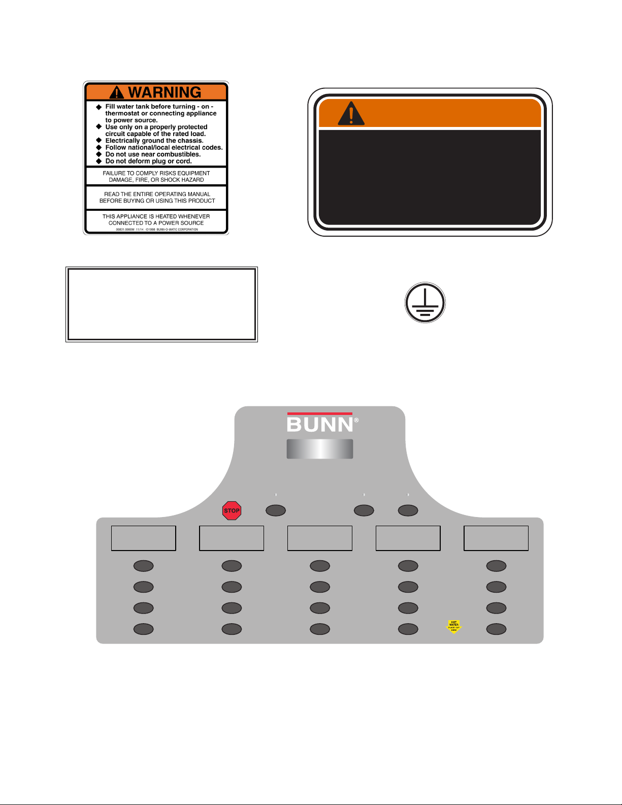
USER NOTICES
The notices on this dispenser should be kept in good condition. Replace unreadable or damaged labels.
WARNING
To reduce the risk of electric shock,
do not remove or open cover.
No user-serviceable parts inside.
Authorized service personnel only.
Disconnect power before servicing.
00831.0000
As directed in the International Plumbing Code of the
International Code Council and the Food Code
Manual of the Food and Drug Administration (FDA),
this equipment must be installed with adequate
backflow prevention to comply with federal, state
and local codes. For models installed outside the
U.S.A., you must comply with the applicable Plumbing /Sanitation Code for your area.
00656.0001
37881.0000
00824.0002
BOX O JOE REDUCED FILL HOT WATER
S
M
L
S
M
L
S
M
L
S
M
L
XL XL XL XL XL
44226.0002
3
S
M
L
45398.2 111315
Page 4

ELECTRICAL REQUIREMENTS
• This appliance must be installed in locations where it can be overseen by trained personnel.
CAUTION - The dispenser must be disconnected from the power source until specified in Electrical Hook-Up.
• For proper operation, this appliance must be installed where the temperature is between 5°C to 35°C.
The 120/208-240 volt version of this dispenser has an attached cordset. The mating connector must be a NEMA
• Appliance shall not be tilted more than 10° for safe operation.
L14-30R.
• An electrician must provide electrical service as specified in conformance with all local and national codes.
• This appliance must not be cleaned by water jet.
Electrical Hook-Up
• This appliance can be used by persons aged from 18 years and above if they have been given supervision or
CAUTION - Improper electrical installation will damage electronic components.
instruction concerning use of the appliance in a safe way and if they understand the hazards involved.
1. An electrician must provide electrical service as specified.
• Keep the appliance and its cord out of reach of children aged less than 18 years.
2. Using a voltmeter, check the voltage and color coding of each conductor at the electrical source.
• Appliances can be used by persons 18 years and above with reduced physical, sensory or mental capabilities
3. Connect the dispenser to the power source.
or lack of experience and knowledge if they have been given supervision or instruction concerning use of the
4. Place the main ON/OFF switch in the “ON” position.
appliance in a safe way and understand the hazards involved.
5. Place the ON/OFF/NIGHT switch in the “ON” position.
• Children under the age of 18 years should be supervised to ensure they do not play with the appliance.
6. If plumbing is to be hooked up later be sure the dispenser is disconnected from the power source. If plumb-
• If the power cord is ever damaged, it must be replaced by the manufacturer or authorized service personnel
ing has been hooked up, the dispenser is ready for Initial Fill & Heat.
with a special cord available from the manufacturer or its authorized service personnel in order to avoid a hazard.
• Machine must not be immersed for cleaning.
• Cleaning and user maintenance shall not be made by children unless they are older than 18 years and supervised.
• This appliance is intended to be used in household and similar applications such as:
– staff kitchen areas in shops, offices and other working environments;
– by clients in hotels, motels and other residential type environments;
– bed and breakfast type environments.
• This appliance not intended to be used in applications such as:
– farm houses;
• Access to the service areas permitted by Authorized Service personnel only.
• The A-Weighted sound pressure level is below 70 dBA.
CE REQUIREMENTS
NORTH AMERICAN REQUIREMENTS
• This appliance must be installed in locations where it can be overseen by trained personnel.
• For proper operation, this appliance must be installed where the temperature is between 41°F to 95°F (5°C to
35°C).
• Appliance shall not be tilted more than 10° for safe operation.
• An electrician must provide electrical service as specified in conformance with all local and national codes.
• This appliance must not be cleaned by pressure washer.
• This appliance can be used by persons aged from 18 years and above if they have been given supervision or
instruction concerning use of the appliance in a safe way and if they understand the hazards involved.
• Keep the appliance and its cord out of reach of children aged less than 18 years.
• Appliances can be used by persons 18 years and above with reduced physical, sensory or mental capabilities
or lack of experience and knowledge if they have been given supervision or instruction concerning use of the
appliance in a safe way and understand the hazards involved.
• Children under the age of 18 years should be supervised to ensure they do not play with the appliance.
• If the power cord is ever damaged, it must be replaced by the manufacturer or authorized service personnel
with a special cord available from the manufacturer or its authorized service personnel in order to avoid a hazard.
• Machine must not be immersed for cleaning.
• Cleaning and user maintenance shall not be made by children unless they are older than 18 years and supervised.
• This appliance is intended for commercial use in applications such as:
– staff kitchen areas in shops, offices and other working environments;
– by clients in hotel and motel lobbies and other similar types of environments;
• Access to the service areas permitted by Authorized Service personnel only.
4
45398.2 111315
Page 5

PLUMBING REQUIREMENTS
This dispenser must be connected to a COLD WATER system with operating pressure between 20 and 100 psi
(0.138 and 0.690 MPa). This water source must be capable of producing a minimum flow rate of 4.5 fl. oz.
(133.1 ml) per second. A shut-off valve should be installed in the line before the dispenser. Install a regulator in
the line when pressure is greater than 100 psi (0.690 MPa) to reduce it to 50 psi (0.345 MPa). The water inlet
fitting is .38” (9.52 mm) flare.
NOTE - Bunn-O-Matic recommends 1⁄4” copper tubing for installations of less than 25 feet and 3⁄8” for more
than 25 feet from the 1⁄2” water supply line. At least 18 inches of an FDA approved flexible beverage tubing,
such as reinforced braided polyethylene or silicone, before the dispenser will facilitate movement to clean the
countertop. Bunn-O-Matic does not recommend the use of a saddle valve to install the dispenser. The size and
shape of the hole made in the supply line by this type of device may restrict water flow.
As directed in the International Plumbing Code of the International Code Council and the Food
Code Manual of the Food and Drug Administration (FDA), this equipment must be installed with
adequate backflow prevention to comply with federal, state and local codes. For models installed
outside the U.S.A., you must comply with the applicable Plumbing /Sanitation Code for your area.
NOTE - If a backflow preventer is required by code, a shock arrestor should be installed between backflow pre-
venter and dispenser. Installing the shock arrestor as close to the dispenser as possible will provide the best
results.
NOTE - Water pipe connections and fixtures directly connected to a potable water supply shall be sized, installed
and maintained in accordance with federal, state and local codes.
PLUMBING HOOK-UP
1. Flush the water line and securely attach it to the elbow fitting on the back of the dispenser.
2. Turn on the water supply.
INITIAL FILL & HEAT
1. Turn on the water supply and connect the dispenser to the power source.
2. Open the front door and place the ON/OFF/NIGHT switch in the “ON” (upper) position.
3. Turn main power switch “ON”. Water will automatically flow into the tank to the proper level and then shutoff. This will take less than ten minutes.
4. Fill the hopper(s) with the dry product to be dispensed.
LIQUID LEVEL CONTROL
The system automatically maintains the hot water tank’s level by energizing the refill solenoid when the water
level drops below the liquid level probe. If the system has not successfully refilled in 10 minutes, a refill error
occurs. When a refill error occurs, the refill solenoid is de-energized. Once the cause of the refill error has been
investigated and cured, the system can be reset by either turning main power off 5 seconds then turning on, or
unplugging for 5 seconds, or by entering one of the program modes (see Programming, page 17.)
5
45398.2 111315
Page 6

RINSE TIMER
The dispenser is shipped from the factory with the rinse timer enabled. When enabled, the rinse timer automatically keeps track of the time since the dispenser was last run through a rinse sequence. If the dispenser detects
that a rinse sequence has not been run for the desired time, a message will appear on the LCD display. The hopper drives will be disabled until a rinse sequence has been run.
RUNNING A RINSE SEQUENCE
1. Place a container at the position to be rinsed. Place the NORMAL/PROGRAM/RINSE switch (page 18) in the
“RINSE” position.
2. At each position, press any of the dispense switches. The dispenser will run for 10 seconds with the
hopper(s) disabled.
3. As each position is rinsed, the LCD display will show which position is being rinsed and count down from
10 seconds.
4. After all positions have been rinsed, return the NORMAL/PROGRAM/RINSE switch to the “NORMAL” position.
DISPENSER USE - Portion Control
1. Simply place a cup on the drip tray beneath the desired dispensing tip.
2. Select the appropriate button for the cup size under the dispense tip, press momentarily, then release.
3. For Box O Joe or Reduced Fill, press that button then select a drink size for that product of choice (within 3
seconds).
4. Let the mixing chamber completely drain before removing cup.
DISPENSE HOT WATER - Portion Control
1. Place cup under hot water dispensing tip.
2. Press momentarily and release hot water button then appropriate size for portion control (within 3 seconds).
Or, Press the hot water button a second time and release when desired volume is reached for push and hold.
LCD Display Key
The LCD will display the size and head currently being dispensed.
1-5 for the heads
HW for hot water
B for Box of Joe
For example:
S for small
M for medium
L for large
X for x-large
2B is head 2 Box of Joe
3m is a reduced fill medium on head 3
HWL is a large hot water portion
HWP for push and hold hot water
HWS for small portion hot water
Lower case letters show that reduced fill is active
PREVENTIVE MAINTENANCE
Bunn-O-Matic® Corporation recommends that preventive maintenance be performed at regular intervals. Maintenance
should be performed by a qualified service technician. For Technical Service, contact Bunn-O-Matic® Corporation at
1-800-286-6070.
NOTE: Replacement parts or service caused by failure to perform required maintenance is not covered by warranty.
Cycle
(months)
Item Part Number
6
Mixing Chamber Kit 32906.0001
3 or as
needed
Whipper Shaft Seal Kit 26356.1000
6
45398.2 111315
Page 7
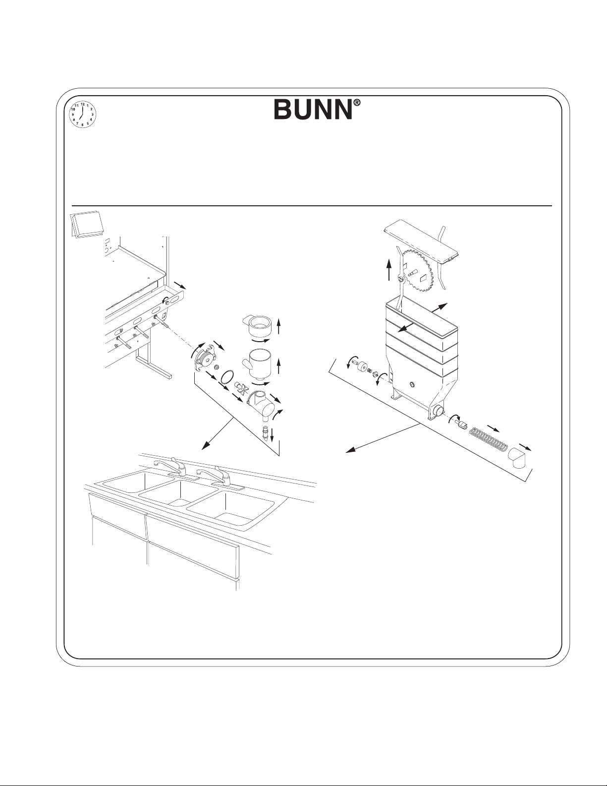
CLEANING
The use of a damp cloth rinsed in any mild, non-abrasive, liquid detergent is recommended for cleaning all surfaces on Bunn-O-Matic equipment. Do NOT clean this equipment with a water jet device.
1 x 24h
1. Rinse out Whipper Chambers by placing
NORMAL/PROGRAM/RINSE switch in the "RINSE"
position and activating DISPENSE switches.
2. Turn elbow up, remove Hoppers, refill with product and
replace hoppers into dispenser
3. Empty Drip Tray and wash in a solution of dish detergent.
1 x 7d
7
.
9
6
8
7
5
1. Para limpiar las camaras de mezcla, coloque el interruptor en la posicón
NORMAL/PROGRAMACIÓN/ENJUAGUE (”NORMAL/PROGRAM/ RINSE”) y
pulse el boton para espumar y distribuir la bebida (”DISPENSE”).
2. Gire el codo hacia arriba, remueva las tolvas, llene las tolvas con producto
y coloque las tolvas nuevamente en la maquina.
3. Vacie la bandeja de goteo y limpiela con un detergente liquido suave no
abrasivo.
1
2
3
4
a
b
c
d
a. Wash
b. Rinse
c. Sanitize
d. Dry
a. Lave
b. Enjuague
c. Desinfecte
d. Seque
NOTICE
The cleaning instructions noted above are for non-dairy sugar based food products. When dispensing any other food product,
the cleaning cycle for the whipping chamber assembly and ejector elbow must be performed daily.
NOTA:
Las instrucciones de limpieza descritas anteriormente excluyen productos lacteos azucarados. La limpieza de las camaras
de mezcla y de los codos de salida de cada tolva deberá realizarse diariamente.
37254.0002B 10/11 © 2011 BUNN-O-MATIC CORPORATION
7
45398.2 111315
Page 8

WATER & POWDER CALIBRATION
NOTE: You will need a gram scale and containers to catch powder and water.
1. Fill hoppers.
2. Rinse all heads prior to calibration.
3. Lift door, place switch in Program position.
4. Press HOT WATER button button until “Calibration” screen. Press “Yes”.
CALIBRATION ?
EXIT YES
5. Press HOT WATER button until “Cal Water X?”
(where X is head to be calibrated)
7. The unit will automatically dispense for ten seconds.
8. Press HOT WATER button, the screen should
change to “Enter Volume” Enter the volume of
water captured in graduated cylinder (in ounces).
(Use a 5 run average)
ENTER VOLUME 1
(-) 11.0 oz (+)
9. Press HOT WATER button, the next screen should
be “Cal Powder X?” (where X is head to be calibrated)
CAL WATER 1 ?
PRESS DISPENSE
6. Place container under dispense head being tested.
Then press and release membrane dispense button for the dispense head being tested.
CAL POWDER 1 ?
PRESS DISPENSE
8
45398.2 111315
Page 9

WATER & POWDER CALIBRATION (Continued)
10. Remove mixing components from dispense head
being tested. Tare catch cup and place under hopper elbow of dispense head being tested.
13. Repeat for all stations.
14. Return Program switch to Normal.
15. Two large dispenses are required for auger motors to adjust if new calibration values have been
entered.
11. Then press and release membrane dispense button for the dispense head being tested. The unit
will automatically dispense for ten seconds. Run
one cycle but do not use results this primes system.
12. Press HOT WATER button, the screen should
change to “Enter Weight X” (where X is head to be
calibrated). Then weigh the catch cup with powder
and enter the weight (in grams). (Use a 5 run average)
ENTER WEIGHT 1
(-) 54.5 gm (+)
9
45398.2 111315
Page 10

HOPPER DISPENSE RATE OF PRODUCT
The hopper dispense rates are preset at the factory. With 30 tooth gear and auger wire, the preset dispense
rate is approximately 5 to 7 grams per second. The hopper dispense rates can be individually programmed to a
range of dispense rates from approximately 1.5 to 12 grams per second, by following the procedures described
in Programming Modes.
HOPPER LEVEL SENSOR CALIBRATION
The dispenser is equipped with sensors to detect a low level in each hopper. When low powder lockout is
enabled, dispensing will be disabled when a low powder condition is detected in a hopper. The LCD screen on
the door will also display a low level condition.
The despenser is shipped from the factory with the low level powder Enabled. To disable the lock, place
the “NORMAL/PROGRAM/RINSE” switch (page 18) in the “PROGRAM” position. Press HOT WATER button.
Continue to press this button until the “LOCKS/DISABLES?” menu is reached. Press REDUCED FILL button for
“YES” then press BOX O JOE button for “NO”. The low powder lockout is now disabled. Press Hidden button
to exit the program menus, then return the “NORMAL/PROGRAM/RINSE” button to the “NORMAL” position.
To enable the low powder lockout, repeat the process, and press REDUCED FILL button for “YES”, in the “LOW
POWDER LOCK” menu.
The low level sensors are factory calibrated for most products. If calibration is required for proper operation, the sensors can be recalibrated to the current product.
The hopper must be at least half full of product for calibration. Place the “NORMAL/PROGRAM/RINSE”
switch in the “PROGRAM” position. Using HOT WATER button, forward until the “CALIBRATION?” menu is
reached. Press REDUCED FILL button for “YES”, then press HOT WATER button until “CAL HOPPER 1 LPD”
screen is reached. Continue to press button A until the hopper to be calibrated is reached.
To calibrate the hopper, press REDUCED FILL button to indicate “YES” in the “CAL HOPPER 1 LPD” screen.
The screen will then ask you if the hopper is full. Press the button again to indicate “YES”. The calibration will
then take a few moments, then the screen will display “POWDER LEVEL RESET COMPLETE”. The next hopper
may be calibrated by moving forward in the menu, or press Hidden button to exit.
DRAINING THE HOT WATER TANK
CAUTION - The dispenser must be disconnected from the power source throughout these steps
1. Disconnect the dispenser from the power source.
2. Open front door and place ON/OFF/NIGHT switch in the “OFF” (center) position and let the water in the tank
cool before draining.
3. Shut off and disconnect the incoming water supply.
4. Remove the drip tray and access panels below the door.
5. Pull the clamped end of the silicone tube out of the dispenser and direct it into a drain or a container large
enough to hold the volume of water in the tank (7.3 gal).
6. Make certain the shut off clamp is locked tightly on the tube, then remove the snap type clamp and plug from
end of tube.
7. Carefully release the shut off clamp to let the water drain from the tank.
NOTE - The dispenser must be refilled using the INITIAL FILL & HEAT steps, page 5.
10
45398.2 111315
Page 11

USB FUNCTION
Enter Program mode, go to USB Menu Screen and press yes.
This screen will force the IMIX main board to try to establish communications with the USB Board. The
display will then show the software versions of both the main and USB board.
Installing new IMIX-5 HWB Software via a USB Flash Drive and Uploading new recipes
Prepare USB Flash Drive for Software Download.
NOTE: Updating software or recipes will require re-calibration.
1. Open the front stainless steel door of the HWB machine and flip the toggle
switches (located to the right of the head 5 whipper chamber) to their top positions
(NORMAL and ON, respectively).
2. Remove the black USB port protective plug from between the two toggle switches and insert the desired USB Flash Drive into the port.
3. Wait approximately five to ten seconds (if you have an LED on your flash drive, it should light up now) and
then remove the USB flash drive from the machine and take it to your computer. The purpose of this step is
for the machine to create the necessary directory structure on your USB Flash Drive – after you have done this
directory creation procedure once for a particular flash drive you can simply start this reprogramming guide at
#4 when doing a future software update.
11
45398.2 111315
Page 12

How to Download Software from your Computer E-mail to the USB Flash Drive
4. Insert the USB Flash Drive into a USB port on your computer (from this point on, we will assume that the
flash drive is mounted to your computer as the drive letter “E:\”).
5. Navigate to the following directory on the USB Flash Drive:
“E:\BUNN_USB\IMIXHWB0\SOFTWARE\”
6. In your e-mail, you should have an attachment containing the machine software that is a file consisting of a
name exactly 8 characters long that ends in the extension “.BIN”. Save this file to the newly opened directory on
your USB Flash Drive from step 5. Note that going forward that there can be only one “.BIN” file in this directory
for this procedure to work.
7. Once this has been completed, please safely remove the USB thumb drive from your PC.
Loading Software / Reprogramming The Machine
8. Take your thumb drive back over to the HWB unit and plug it in to the USB port on the machine.
9. Wait about five seconds for the thumb drive to pair up, then flip the top most toggle switch inside the machine to the middle position (this will be the PROGRAM position), making sure that the bottom toggle switch is
in the top position (this is the ON position).
10. Close the door on the HWB machine. The 2x16 display should now say the following:
PROGRAM MODE !!!
PRESS FORWARD SW
11. Press and release the HOT WATER button on the membrane switch to step through
the menu screens of program mode. Keep on pressing and releasing the HOT WATER
button until you run across a screen that says the following:
ENTER USB MENU ?
EXIT YES
12. Once on that screen, press the REDUCED FILL button to enter this menu screen. The HWB machine will
begin to communicate with the USB Board. Once the pairing takes place, the screen should alternate between
showing the USB Board version and the HWB machine version. It will look similar to the following format (using
00.99 and 04.08 as example software versions):
iMIX VERS 00.99 <--every three seconds--> USB VERS 04.08
PRESS FORWARD <--this will alternate--> PRESS FORWARD
12
45398.2 111315
Page 13

13. Press the HOT WATER button again to go to the screen that will allow you to reprogram the HWB machine.
It will look like the following:
REPRGM IMIXHWB0?
EXIT YES
14. Press the REDUCED FILL button on this screen and the reprogramming process will start.
15. Within 15 seconds, the actual reprogramming will fully begin, and the current software version will come up
on the screen for the duration of the reprogramming process as follows:
BUNN iMIX
iMIX VERS 00.99
Where 00.99 would be an example of the number of the current (old) software version.
16. It may take up to two minutes for the reprogramming process to complete. During this time, the machine
will appear unresponsive, and if your USB Flash Drive has an indicator LED on it, it should be actively blinking
to indicate that the reprogramming activity is occurring.
17. When the software update has successfully completed, the machine should show the new software version
number briefly on the screen as follows:
BUNN iMIX
iMIX VERS 01.07
Where 01.07 is an example of the number of the new software version from your e-mail.
18. The entire process is only fully complete and the machine ready for further interaction when the display
comes back to saying the same text about program mode as shown in #9 up above:
PROGRAM MODE !!!
PRESS FORWARD SW
13
45398.2 111315
Page 14

Machine Functional Checkout / Verifying the Software Update / Final Steps
19. If you want to confirm that the new version of software has taken successfully, you can power cycle the
machine (by shutting it off for approximately five seconds) and then turning it back on and verifying that the
version number that comes up on the display is indeed the new software version number (ie. 01.07) and not the
old version (ie. 00.99).
NOTICE: Beyond that mentioned above, you will have to refer to specific documentation about the newly implemented functions or features that have been added in the new version of HWB software you are loading to
ensure that they are properly installed, set up, and functional.
20. Once the reprogramming has completed successfully, remove the flash drive from the HWB machine, place
both toggle switches in the upper most positions again (NORMAL and ON), and the machine should be ready to
return to normal operation.
NOTICE: Once you have the proper directory structure on your USB Flash Drive, you can start this guide at #4.
If you use a different flash drive, you will have to start this guide over at #1.
Updating Recipes from USB Flash Drive With the RECIPES.TXT file in the /RECIPES/ Directory on the Flash
Drive
Follow steps 1 - 12, then 21 and 22
21. Press the HOT WATER button until screen:
IMPORT RECIPES
EXIT YES
22. Press the REDUCED FILL button on this screen and the importing of recipes will start.
14
45398.2 111315
Page 15

Exporting to USB
Enter Program mode, go to USB Menu Screen and press yes.
If you press yes in the “EXPORT DRINKCNT?” screen. The drink counts will be exported to the flash drive and placed
on the USB flash drive at “E:\BUNN_USB\IMIXHWB0\DRINKCNT\” and the file will be named DC######.TXT (where
###### is the six digit serial number of the machine the drink counter data was pulled from).
Note the drink counters reset at 50,000. With the exception that the odometer would roll over at 10 digits.
If you press YES in the “EXPORT DRINKHST?” screen. The drink histories will be exported to the flash drive and
placed on the USB flash drive at “E:\BUNN_USB\IMIXHWB0\DRINKHST\” and the file will be named DH######.TXT
(where ###### is the six digit serial number of the machine the drink counter data was pulled from).
Note if the USB board sees more than 1350 drinks without receiving an export drink history command. It will export
the data to a flash drive if one is installed in machine or as soon as one is installed. If no flash drive is found any drinks
over 1350 will start writing over the oldest data. When exporting drink history, fault history will also be exported. The
file will be named FH######.TXT (where ###### is the six digit serial number of the machine the drink counter data was
pulled from). Fault history will overwrite old data if no flash drive is present and over 300 faults have been logged. When
exporting drink counts, drink history and fault history one backup file is created on the USB drive (.bak).
Drink History key:
Drink
1=Head 1
2=Head 2
3=Head 3
4=Head 4
5=Head 5
6=Hot Water
91=Rinse Head 1
92=Rinse Head 2
93=Rinse Head 3
94=Rinse Head 4
95=Rinse Head 5
Size
0=Null
1=Small
2=Medium
3=Large
4=X-large
5=Box
11=Short Small
12=Short Medium
13=Short Large
14=Short X-Large
xx.xx=Rinse Run Time
Fault key:
Fault Element Event Event
Number Number Name
605 1 Dispense STOP
605 3 All Heads Rinsed
605 72 Drink Counters Reset
605 49 Factory Defaults Restored
1750 0 Refill Too Long Fault
1751 0 Heating Too Long Fault
1752 0 Overflow Safety Fault
1753 0 Temperature Sensor Open
1754 0 Temperature Sensor Short
1769 0 Powder Hopper 1 Empty
1770 0 Powder Hopper 2 Empty
1771 0 Powder Hopper 3 Empty
1772 0 Powder Hopper 4 Empty
1773 0 Powder Hopper 5 Empty
1774 0 Station 1 Locked
1775 0 Station 2 Locked
1776 0 Station 3 Locked
1777 0 Station 4 Locked
1778 0 Station 5 Locked
1794 0 Entire Dispenser Locked
1796 0 Rinse Cycle Cleaning Due
1797 0 Rinse Cycle Required and Locked
1803 0 Auger 1 Fault
1804 0 Auger 2 Fault
1805 0 Auger 3 Fault
1806 0 Auger 4 Fault
1807 0 Auger 5 Fault
1810 0 Cannot Communicate With The Display Board
1814 0 Memory Module Locked
1831 0 Dispense Too Long Fault/Membrane Switch Stuck Fault
2045 0 Faults Cleared
2047 0 Machine Powered Up
15
45398.2 111315
Page 16

TANK TEMP XXX°
(-) EXIT (+)
GLOSSARY
Adjust tank temperature: Range 50-190°F
Default setting leaving factory 190° F
AUDIBLE ALARM ?
NO EXIT YES
Turns on audio alarm
READY TEMP XXX°
(-) EXIT (+)
SET CUP SIZE
EXMPL TIME
DISPENSE TO ADD
REPEAT SAVE
DRINK STRENGTH
(-) XX (+)
XX° CAL XX°
(-) Tank Temp (+)
235 REFILL 155
(-) EXIT (+)
CAL WATER ?
PRESS DISPENSE
CAL POWDER ?
PRESS DISPENSE
Auger Delay
(-) .XX sec (+)
CAL HOPPER # LPD
NO YES
LOW POWDER LOCK ?
NO EXIT YES
DISPENSE LOCKOUT
NO EXIT YES
EXPORT DRINKHST?
EXIT YES
HEAD 1 DISABLE ?
NO EXIT YES
ENTER USB MENU ?
EXIT YES
STOPPED DISPENSE
COUNTS #####
RINSE COUNTS
SELECT A HEAD
REPRGM IMIXHWB0?
EXIT YES
REPROGRAM USB ?
EXIT YES
EXPORT DRINKCNT?
EXIT YES
SET PASSWORD ?
(-) XXXX (+)
Adjust minimum tank ready temperature
for lockout. 188° maximum setting and
default setting leaving factory 175°F
Select setting cup size by Time (seconds)
or by Example
Press same dispense button to top off cup, or
press save to lock in dispense time, or, press
repeat to erase dispense time and repeat process
Adjust hopper motor speed
for station selected
Calibrate temperature probe
Set refill probe threshold
Calibrates dilution water flow
rate in station selected
Calibrates powder dispense rate
for hopper in station selected
Set delay start of hopper after dilution
valve opens in station selected
Calibrates hopper level sensor in station selected
Hopper must be at least half full to calibrate
Enables lockout of dispensing when low
hopper level is detected
Enables lockout of dispensing if below
minimum water temperature
Allows downloading the drink history data to
a USB flash drive plugged into the machine
Disables all functions and dispensing
for station selected
Forces the IMIX main board to try to establish communications with the USB Board
Shows the total number of portion control
dispenses that have been stopped
Shows the number of rinse cycles successfully completed for an individual head
Allows reprogramming the main IMIX
board with a flash drive plugged in
Allows reprogramming the USB Board with
a flash drive plugged in
Allows downloading the drink counter data to
a USB flash drive plugged into the machine
Allows password to be set to prevent altering setup functions
16
DISABLE MESSAGES ?
NO EXIT YES
ENABLE ADS ?
NO EXIT YES
ENTER ASSET # ?
EXIT YES
ENABLE SERVICE #
NO EXIT YES
TEST SWITCHES ?
Use Switch To Test
TEST HEATER ?
EXIT YES
TEST REFILL ?
EXIT YES
TEST HOT WATER ?
EXIT YES
TEST AUGERS ?
DISPENSE TO TEST
DISPLAY USAGE ?
EXIT YES
FACTORY DEFAULTS
NO YES
RINSE ALARM ?
NO EXIT YES
VIEW DRINK CNTS?
EXIT YES
ODOMETER
##########
iMIX VERS ##.##
PRESS FORWARD
USB VERS ##.##
PRESS FORWARD
HOT WATER COUNTS
SELECT A SIZE
SELECT A PORTION
TO VIEW COUNTS
RESET COUNTERS ?
NO EXIT YES
HEAD #X RECIPE
RECIPE NAME
IMPORT RECIPES
EXIT YES
Disables function that displays fault
messages on LCD door display
Enables “ADS” to be displayed
on LCD door display
Enter asset number of machine
Enables service agent telephone
number to be displayed
Allows testing of dispense
switches
Allows manually activating
tank heater
Allows manually activating
refill valve
Allows manually activating hot
water valve
Allows manually activating
hopper motors
Displays amount dispensed
Resets all functions to factory
defaults, and password to 0
Enables rinse alarm
Allows access to the drink counters
Shows the total machine odometer
counter
Alternates between displaying the
software version number of the USB
Board and the IMIX HWB main board
Shows the number of hot water
portion control dispenses
Shows the number of portion size
dispenses for a given size
Allows resetting all the drink counters
(except for the master odometer)
Name of recipe currently on Head X
Import Recipes from USB Drive
45398.2 111315
Page 17

PROGRAMMING THE DISPENSER
The following function screens are in order of appearance. Each screen will have instructions on how to
access, and the procedures to program the various functions of the dispenser. To enable programming, place
the “NORMAL/PROGRAM/RINSE” switch in the “PROGRAM” position.
IMPORTANT PROGRAMMING NOTES - READ CAREFULLY
To exit the programming mode at any time, press and release the EXIT (any XL button) pad located on the
front switch panel. The display will return to the PROGRAM HOME SCREEN. Exception - any screen where the
XL button will trigger a dispense or is used to display data on the screen.
If none of the five programming switches are pressed within 90 seconds during the setup of the dispenser,
the programming of the function screen that is being set will be exited and the display will return to the PRO-
GRAM HOME SCREEN.
PROGRAMMING SWITCHES
E
BACK
S
M
L
S
M
L
D
-
BOX O JOE REDUCED FILL HOT WATER
C
EXIT
S
M
L
B
+
A
FWD
S
M
L
XL XL XL XL XL
S
M
L
A. Enter program mode and advance to next menu
B. Increment display value positive
C. Exit program mode (any XL button)
D. Increment display value negative
E. Return to previous menu and interrupt dispense
Using the menu-driven display (MAIN SCREEN) on the front of dispenser, the operator has the ability to
alter or modify various functions of the dispenser. This allows for precise dispensing of various flavors of
powdered products.
Programming of dispenser is achieved by entering a certain function, then, by use of programming switches, the operator can customize the dispensing process to their specifications.
To access the programming mode, and to scroll through different function screens, the programming
switches shown are used. There are five of these switches that will be used for setup of the dispenser.
17
45398.2 111315
Page 18

PROGRAMMING THE DISPENSER (cont.)
1. ON/OFF/NIGHT switch:
ON: Enables all dispenser functions.
2
OFF: Disables all dispenser functions.
NIGHT: Night Mode Energy Saver disables display lighting and dispense switches. Tank
temperature drops to 140°F and holds it there.
2. NORMAL/PROGRAM/RINSE switch:
NORMAL: Allows all dispenser functions. Must be in this position for dispensing.
PROGRAM: Allows access to program menus using touch pad and LCD screen.
1
RINSE: Disables hopper motors. Pressing dispense button on front door will dispense
dilution water and power whipper motor for ten seconds.
PROGRAMMING CUP SIZES
The cup size can be programmed in portion control models by “EXAMPLE” or “TIME”. Programming by EXAMPLE is
manually pressing desired dispense button, then releasing when the desired cup size is attained. The time required to fill
the cup will be stored in the controller memory by pressing REDUCED FILL to save. Programming by TIME is setting the
actual dispense time in seconds for each cup size desired.
Place the “NORMAL/PROGRAM/RINSE” switch in the “PROGRAM” position. Press HOT WATER button until the “SET
CUP SIZE” menu is reached. (Refer to menu N, page 23) Press BOX O JOE button to select programming by “EXAMPLE”.
Place proper cup under dispense tip for station you desire to set. Press desired dispense button, then release when the
cup is 3/4 full. If cup is not full enough, the dispense button can be pressed again to add additional beverage to the cup. If
cup has reached desired level, press REDUCED FILL button under “SAVE” to record the dispense time. If cup is overfilled,
press button D under “REPEAT”. Empty cup and repeat the process.
If setting cup sizes by “TIME” is desired, press button REDUCED FILL under “TIME” in the “SET CUP SIZE” menu.
“HEAD 1 SM TIME” will be displayed, along with current time setting. Pressing either BOX O JOE button below (-) or
REDUCED FILL button below (+) will subtract or add time in .1 second increments, XL and Box-O-Joe in 1.0 second increments. Each one second of time equals approximately 1.25 ounces of beverage at factory settings. When desired time is
set, press HOT WATER button to continue to next cup size.
When the desired cup sizes have been programmed, press Hidden button to exit program menus, or press button
HOT WATER to move to the next menu. If Hidden button was selected to exit the program mode, return the “NORMAL/
PROGRAM/RINSE” switch to the “NORMAL” position to return to nomal operation.
If recipes have been added to the machine, cup sizes and ratio can also be adjusted by changing the recipe.
Place the “NORMAL/PROGRAM/RINSE” switch in the “PROGRAM” position. Press HOT WATER button until screen:
SET CUP SIZE BY
EXAMPLE TIME
Press Reduced Fill button. Screen will update to:
HEAD #1 RECIPE
RECIPE NAME
Press Reduced Fill button to change recipe. Press Hot Water button to accept change. Press Hot Water button to advance
to other heads if required.
NOTE: If Powder is changed, Powder will need to be re-calibrated.
PROGRAMMING HOT WATER SIZE
Place the “NORMAL/PROGRAM/RINSE” switch in the “PROGRAM” position. Press HOT WATER button until the “SET
CUP SIZE” menu is reached. (Refer to menu D, page 20). Press REDUCED FILL button under “TIME” in the “SET CUP
SIZE” menu. Press foward until “SMALL H/W TIME” and adjust to desired time by pressing BOX O JOE button (-) (page
17) or REDUCED FILL button (+).
Small, Medium, and Large are settable from 1 to 25 seconds in increments on 0.1 seconds, and the Extra Large portion is settable from 1 to 110 seconds in steps of 1.0 seconds. Each one second of time equals approximately 1.0 ounces.
18
45398.2 111315
Page 19

PROGRAMMING THE DISPENSER (cont.)
Press and release right switch (advance to next menu), “TANK TEMP XXX°” appears on screen.
TANK TEMP XXX°
(-) EXIT (+)
READY TEMP XXX°
(-) EXIT (+)
continue to N
(page 17)
(O)
STRENGTH ADJ. ?
EXIT YES
(A)
ENTER PASSWORD
(-) XXXX (+)
Adjust tank
temperature
Adjust minimum tank
ready temperature for
lockout
continue to B
(page 20)
(K)
AUDIBLE ALARM ?
NO EXIT YES
DISABLE MESSAGES ?
NO EXIT YES
ENABLE ADS ?
NO EXIT YES
ENTER ASSET # ?
EXIT YES
(C)
CALIBRATION ?
EXIT YES
(E)
ENTER USB MENU
EXIT YES
(G)
VIEW DRINK CNTS ?
EXIT YES
(I)
LOCKS/DISABLES ?
EXIT YES
continue to D
(page 20)
continue to H
(page 21)
continue to F
(page 21)
continue to J
(page 22)
ENABLE SERVICE ?
NO EXIT YES
DIAGNOSTICS ?
EXIT YES
(M)
DISPLAY USAGE ?
EXIT YES
FACTORY DEFAULTS
NO YES
FINISHED, returns
to main screen
continue to L
(page 22)
19
45398.2 111315
Page 20

PROGRAMMING THE DISPENSER (cont.)
Adjust hopper motor
speed for station for
station selected
DRINK STRENGTH 1
(-) XX (+)
PRESS DISPENSE
TO CHECK TASTE
TASTE 1 OK ?
NO YES
(B)
SET FLAVOR 1 BY
TASTE RECIPE
Goes to next station.
Returns to (A) (page
19) after last station.
CHANGING VALUES
WILL EFFECT RPM
ARE YOU SURE ?
NO EXIT YES
ENTER RECIPE #
#.# gm/fluid oz
(D)
SELECT UNITS
ENG EXIT METRIC
CAL HOPPER 1 LPD
NO YES
HOPPER 1 FULL
NO YES
Goes to next station.
Continues after last
station.
XX° CAL XX°
(-) Tank Temp (+)
CAL POWDER 1 ?
PRESS DISPENSE
ENTER WEIGHT 1
(-) XX.X gm (+)
Goes to next station.
Continues after last
station.
CAL HOT WATER
PRESS TO DISPENSE
Goes to next station.
Returns to (A) (page
19) after last station.
Goes to next station.
Returns to (A) (page
19) after last station.
235 REFILL 155
(-) EXIT (+)
CAL WATER 1 ?
PRESS DISPENSE
ENTER VOLUME 1
(-) XX.X oz (+)
AUGER DELAY
(-) .XX sec (+)
Returns to (E)
(page 19)
20
45398.2 111315
Page 21

PROGRAMMING THE DISPENSER (cont.)
(F)
ODOMETER
XXXXX
STOPPED DISPENSE
COUNTS XXXX
HOT WATER COUNTS
SELECT A SIZE
RINSE COUNTS
SELECT A HEAD
SELECT A PORTION
TO VIEW COUNTS
Alternates between
IMIX VERS ##.#
and
USB VERS ##.#
(H)
IMIX VERS ##.#
PRESS FORWARD
REPRGM IMIXHWBO
EXIT YES
REPROGRAM USB
EXIT YES
EXPORT DRINK CNT
EXIT YES
EXPORT DRINK HST
EXIT YES
RESET COUNTERS
NO EXIT YES
Returns to (I)
(page 19)
IMPORT RECIPES
EXIT YES
Returns to (G)
(page 19)
21
45398.2 111315
Page 22

PROGRAMMING THE DISPENSER (cont.)
(J)
LOW POWDER LOCK ?
NO EXIT YES
DISPENSE LOCKOUT
NO EXIT YES
RINSE ALARM ?
NO EXIT YES
HEAD 1 DISABLE ?
NO EXIT YES
Goes to next station.
Continues after last
station.
RINSE ALARM TIME
(-) XX hours (+)
RINSE LOCKOUT ?
NO EXIT YES
(L)
TEST SWITCHES ?
Use Switch To Test
TEST HEATER ?
EXIT YES
TEST REFILL ?
EXIT YES
TEST HOT WATER ?
EXIT YES
TEST AUGERS ?
DISPENSE TO TEST
SET PASSWORD ?
(-) XXXX (+)
Returns to (K)
(page 19)
TEST DISPENSE HEAD?
DISPENSE TO TEST
Returns to (M)
(page 19)
22
45398.2 111315
Page 23

PROGRAMMING THE DISPENSER (cont.)
(N)
SET CUP SIZE BY
EXAMPLE TIME
Returns to (O)
(page 19)
DISPENSE UNTIL
CUP IS 3/4 FULL
Press and release
any dispense button
to set cup size.
DISPENSE TO ADD
REPEAT SAVE
Returns to (O)
(page 19)
NOTE: Only Small, Medium,
Large, and Extra Large Cup
Sizes can be set by Example.
NOTE: Only heads 1-5 can be
set by example. Hot Water CAN
NOT be set by example.
Goes to next station.
HEAD #1 RECIPE
RECIPE NAME
HEAD 1 SM TIME
(-) 7.40 SEC (+)
HEAD 1 MED TIME
(-) 11.20 SEC (+)
HEAD 1 LG TIME
(-) 15.40 SEC (+)
HEAD 1 XLG TIME
(-) 18.0 SEC (+)
HEAD 1 BOX TIME
(-) 38.0 SEC (+)
After last station.
NOTE: Setting BOX PULSE ON TM
to 99 seconds will effectively disable the pulse for any BOX O JOE
portion size dispense.
NOTE: If the BOX O JOE dispense
time exceeds 2 minutes with the
pulses added in, it will throw a
dispense too long fault.
SMALL SHORT %SMALL H/W TIME
(-) 82.50 % (+)(-) 9.00 sec (+)
MEDIUM SHORT %MEDIUM H/W TIME
(-) 81.40 % (+)(-) 12.70 sec (+)
LARGE SHORT %LARGE H/W TIME
(-) 82.50 % (+)(-) 17.20 sec (+)
X-LARGE SHORT %X-LARGE H/W TIME
(-) 81.90 % (+)(-) 21.0 sec (+)
BOX PULSE ON TM
(-) 99.0 SEC (+)
BOX PULSE OFF TM
(-) 5.0 SEC (+)
Returns to (O)
(page 19)
23
45398.2 111315
 Loading...