

BUNN
REPLACEMENT OF ANY COMPONENT!
BEFORE REMOVAL OF ANY PANEL OR
W
A
R
N
IN
G
®
H5M
DISCONNECT FROM POWER SOURCE
WARNING
!
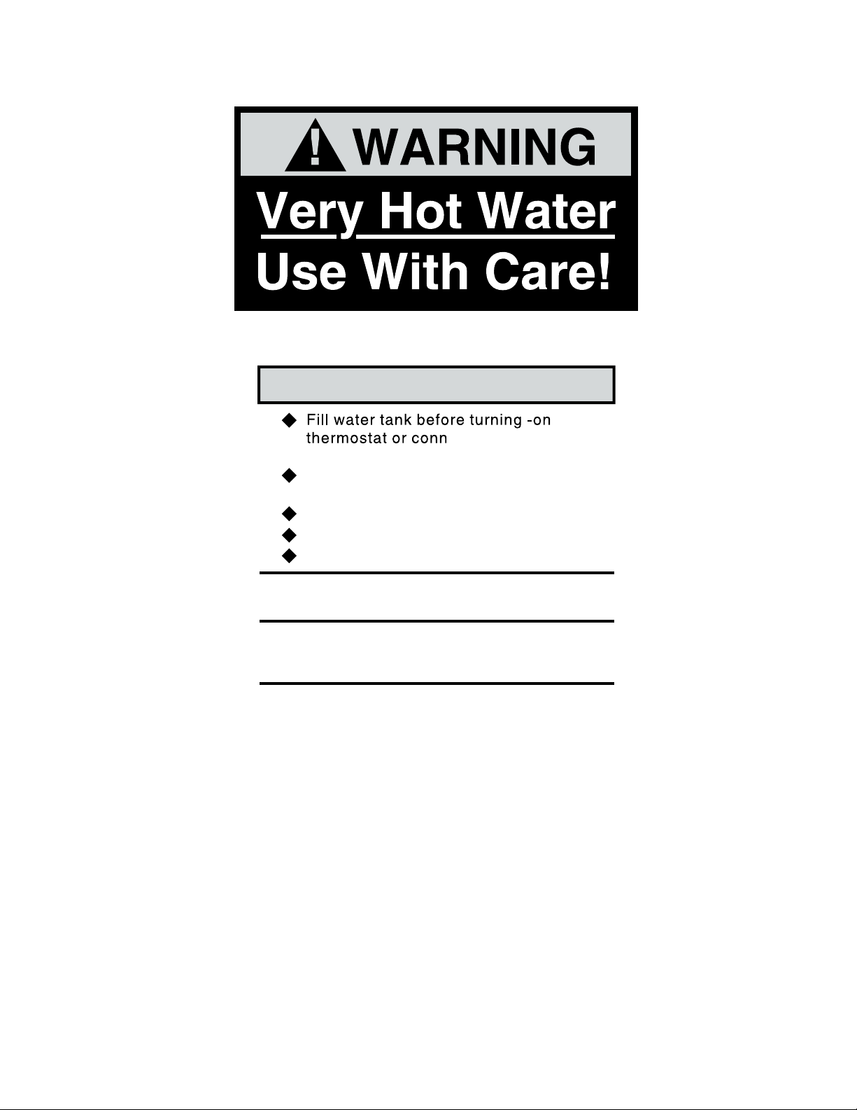
Very Hot Water
Use With Care!
OPERATING & SERVICE MANUAL
BUNN-O-MATIC CORPORATION
POST OFFICE BOX 3227
SPRINGFIELD, ILLINOIS 62708-3227
PHONE: (217) 529-6601 FAX: (217) 529-6644
10267.0000D 7/00 © 1988 BUNN-O-MATIC CORPORATION

CONTENTS
Introduction ................................................. 2
Warranty ...................................................... 2
User Notices ................................................ 3
Electrical Requirements ............................... 4
Plumbing Requirements .............................. 4
Initial Set-Up................................................ 5
Draining the Dispenser ................................ 5
Cleaning....................................................... 5
Troubleshooting .......................................... 6
Service......................................................... 9
Wiring Schematics..................................... 19
INTRODUCTION
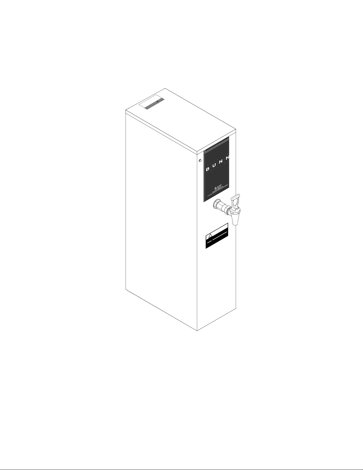
This equipment heats and dispenses water on demand for beverages and cooking purposes. This equipment
is for indoor use, either wall-mounted or on a sturdy counter or shelf.
WARRANTY
Bunn-O-Matic Corp. (“Bunn”) warrants the equipment manufactured by it to be commercially free from defects
in material and workmanship existing at the time of manufacture and appearing within one year from the date of
installation. In addition:
1.) Bunn warrants electronic circuit and/or control boards to be commercially free from defects in material and
workmanship for two years from the date of installation.
2.) Bunn warrants the compressor on refrigeration equipment to be commercially free from defects in material
and workmanship for two years from the date of installation.
3.) Bunn warrants that the grinding burrs on coffee grinding equipment will grind coffee to meet original factory
screen sieve analysis for three years from date of installation or for 30,000 pounds of coffee, whichever comes first.
This warranty does not apply to any equipment, component or part that was not manufactured by Bunn or that,
in Bunn’s judgement, has been affected by misuse, neglect, alteration, improper installation or operation, improper
maintenance or repair, damage or casualty.
THE FOREGOING WARRANTY IS EXCLUSIVE AND IS IN LIEU OF ANY OTHER WARRANTY, WRITTEN OR
ORAL, EXPRESS OR IMPLIED, INCLUDING, BUT NOT LIMITED TO, ANY IMPLIED WARRANTY OF EITHER
MERCHANTABILITY OR FITNESS FOR A PARTICULAR PURPOSE. The agents, dealers or employees of Bunn are
not authorized to make modifications to this warranty or to make additional warranties that are binding on Bunn.
Accordingly, statements by such individuals, whether oral or written, do not constitute warranties and should not
be relied upon.
The Buyer shall give Bunn prompt notice of any claim to be made under this warranty by telephone at (217)
529-6601 or by writing to Post Office Box 3227, Springfield, Illinois, 62708-3227. If requested by Bunn, the Buyer
shall ship the defective equipment prepaid to an authorized Bunn service location. If Bunn determines, in its sole
discretion, that the equipment does not conform to the warranty, Bunn shall repair the equipment with no charge
for parts during the warranty period and no charge for labor by a Bunn Authorized Service Representative during
the warranty period. If Bunn determines that repair is not feasible, Bunn shall, at its sole option, replace the
equipment or refund the purchase price for the equipment.
THE BUYER’S REMEDY AGAINST BUNN FOR THE BREACH OF ANY OBLIGATION ARISING OUT OF THE SALE
OF THIS EQUIPMENT, WHETHER DERIVED FROM WARRANTY OR OTHERWISE, SHALL BE LIMITED, AS
SPECIFIED HEREIN, TO REPAIR OR, AT BUNN’S SOLE OPTION, REPLACEMENT OR REFUND.
In no event shall Bunn be liable for any other damage or loss, including, but not limited to, lost profits, lost sales,
loss of use of equipment, claims of Buyer’s customers, cost of capital, cost of down time, cost of substitute
equipment, facilities or services, or any other special, incidental or consequential damages.
2
10267 071900
3
ELECTRICAL REQUIREMENTS
CON
P
O
N
OFF
Fill
W
!
st l
ffici
ood
Fo
CAUTION - The dispenser must be disconnected from the power source until specified in
Initial Set-Up.
The H5M dispenser requires 2-wire, grounded service rated 120, 208, or 240 volts ac, 20 amp, single phase.
The H5MA, 230V-CE dispenser requires 2-wire, grounded service rated 230 volts ac, 40 amp, single phase, 50/
60Hz
. (Refer to the dispenser’s dataplate for exact voltage requirement.)
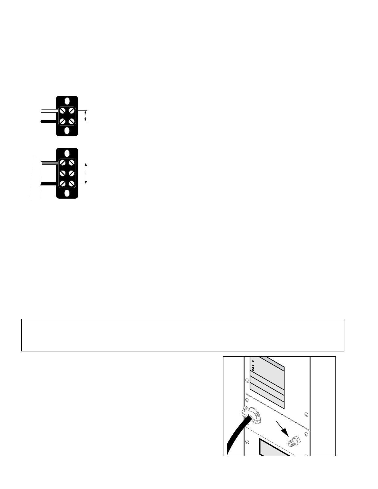
Electrical Hook-Up
CAUTION – Improper electrical installation will damage electronic components.
WHITE
NEUTRAL
L1 BLACK
120V.A.C.
1. An electrician must provide electrical service as specified.
2. Using a voltmeter, check the voltage and color coding of each conductor at
the electrical source.
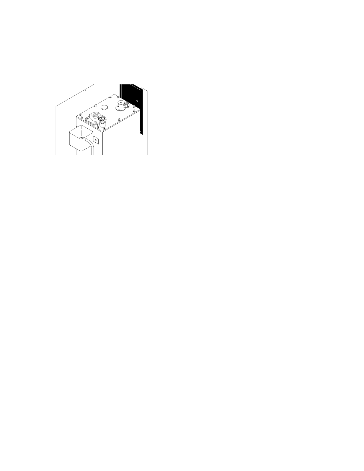
3. Remove the upper and lower rear panels. Turn the knob of the thermostat to
the “OFF” position (fully counterclockwise).
4. Install a strain relief and the proper electrical wiring to the terminal block.
L2 RED
208 or 240V.A.C.
L1 BLACK
5. Connect the dispenser to the power source and verify the voltage at the terminal block before proceeding. Reinstall both rear panels.
6. If plumbing is to be hooked-up later be sure the dispenser is disconnected from
the power source. If Plumbing has been hooked-up, the dispenser is ready for
Initial Set-Up
.
PLUMBING REQUIREMENTS
This dispenser must be connected to a COLD WATER system with operating pressure between 20 and 90 psi (138
and 620 kPa)from a 1⁄2" or larger supply line. A shut-off valve should be installed in the line before the dispenser.
Install a regulator in the line when pressure is greater than 90 psi (620 kPa) to reduce it to 50 psi (345 kPa). The
water inlet fitting is 1⁄4" flare.
NOTE - Bunn-O-Matic recommends 1⁄4" copper tubing for installations of less than 25 feet and 3⁄8" for more than
25 feet from the 1⁄2" water supply line. At least 18 inches of an FDA approved flexible beverage tubing, such as
reinforced braided polyethylene or silicone, before the dispenser will facilitate movement to clean the countertop.
It can be purchased direct from Bunn-O-Matic (part number 00326-0000). Bunn-O-Matic does not recommend
the use of a saddle valve to install the dispenser. The size and shape of the hole made in the supply line by this type
of device may restrict water flow.
This equipment must be installed to comply with the Basic Plumbing Code of the Building Officials
and Code Administrators International, Inc. (BOCA) and the Food Service Sanitation Manual of the
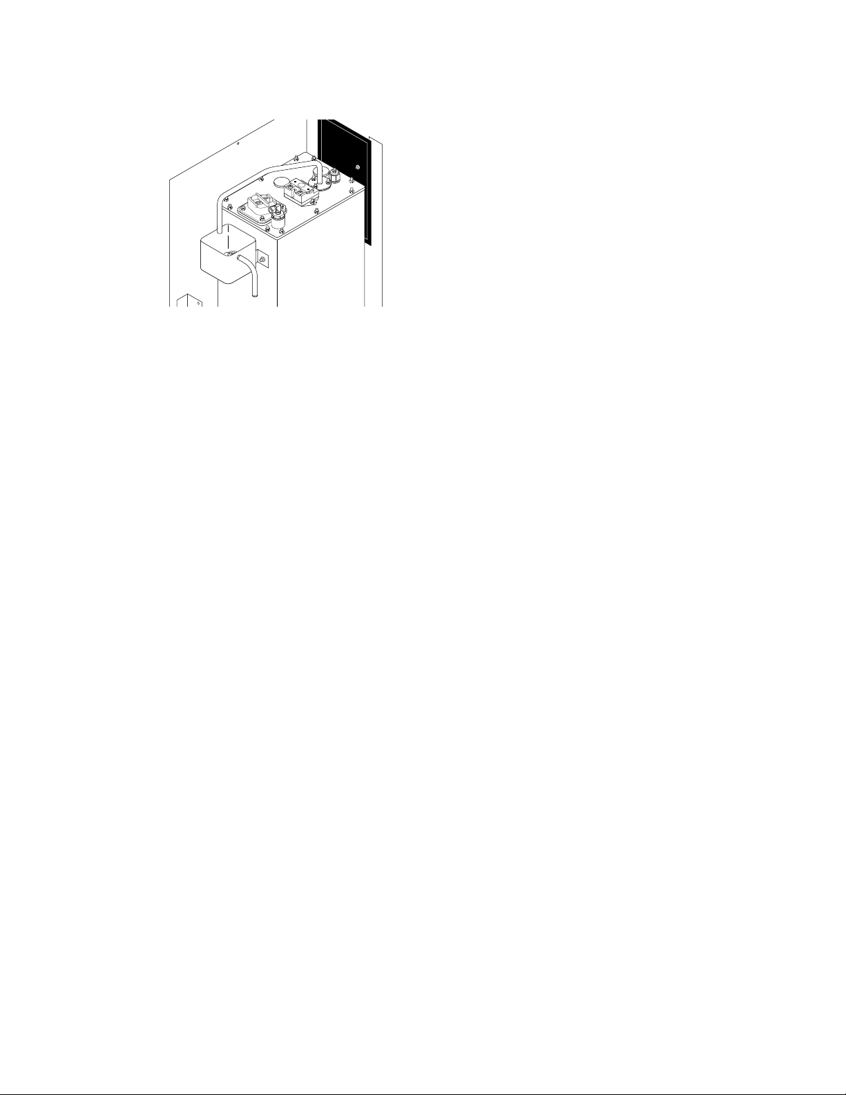
Plumbing Hook-Up
1. Flush the water line and securely attach it to the flare fitting on
Food and Drug Administration (FDA).
water tank before turning -on
thermostat or connecting appliance
ARNING
to power source.
Use only on a properly protected
circuit capable of the rated load.
Electrically ground the chassis.
Follow national/local electrical codes.
Do not use near combustibles.
FAILURE TO COMPLY RISKS EQUIPMENT
DAMAGE, FIRE, OR SHOCK HAZARD
R
E
AD
LIAB
IN
TH
C
LU
ILITY B
E E
D
ING
NTIR
EFO
TH
E O
E
R
LIM
E BU
TH
PER
IS A
IT O
AT
YIN
P
IN
F W
C
PLIA
G
O
G
O
NN
M
AR
R
NC
U
EC
R
00831.0000A 5/88 © 1988 BUNN-O-MATIC CORPORATION
SIN
A
E IS H
TED
N
G
TO
TH
EA
A
TED
PO
W
W
H
E
ENE
R SO
U
NECT FROM
OWER SOURCE
BEFORE REMOVING!
AN
UA
TY
L
A
N
IS PR
D
O
DU
CT
VE
RCE
R
the rear of the dispenser.
2. Turn-on the water supply.
This equipment is to be in
comply with the Basic Pl
Administrators
the Building O
and the F
of the
P1770
4
10267 071900
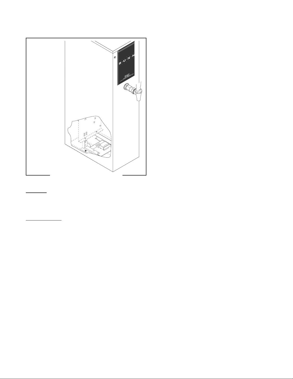
INITIAL SET-UP
CAUTION - The dispenser must be disconnected from the power source throughout the initial set-up, except
when specified in the instructions.
1. Remove the upper rear panel and rotate the control thermostat
knob fully counterclockwise to the “OFF” position and replace
the panel.
2. Connect the dispenser to the power source and turn-on the water
supply.
3. Water will automatically flow into the tank to the proper level
and shut-off. This will take approximately 10 minutes.
4. Disconnect the dispenser from the power source, remove the
upper rear panel and place the control thermostat knob fully
clockwise to the “ON” position, and replace the panel.
5. Connect the dispenser to the power source and wait approximately twenty minutes for the water in the tank to heat.
6. On models with ready indicator, the indicator will glow when the
proper water temperature for use is achieved.
P1781
DRAINING THE DISPENSER
CAUTION - The dispenser must be disconnected from the power source throughout these steps.
1. Disconnect the dispenser from the power source.
2. Shut-off and disconnect the incoming water supply
3. Remove the 4-40 screws at the sides of the top panel.
4. Gently remove one of the grommets from the tank lid.
5. Insert a tube to the bottom of the tank and syphon ALL of the water out. Bunn-O-Matic has a syphon assem-
bly available (#12440.0000) for this purpose.
NOTE - The dispenser must be full using the INITIAL SET-UP steps before reconnecting to the power source.
CLEANING
The use of a damp cloth rinsed in any mild, non-abrasive, liquid detergent is recommended for cleaning
all surfaces on Bunn-O-Matic equipment.
WALL MOUNTED INSTALLATION
If the dispenser is wall mounted, the bottom of the dispenser should be at the same height as a counter or
table top. Use B.O.M. part #12542.0000 for side mounted Wall Bracket Kit or # 13125.0001 for front mounted
Wall Bracket Kit .
SUPPORT FOR LARGE RECEPTACLES
CAUTION: If the dispenser is to be used with larger receptacles such as pitchers or pots, those receptacles must
be adequately supported during dispensing of hot water to avoid spillage of very hot water. This support may be
provided by a table or counter top, or use B.O.M. part #12599.0000 Shelf Kit
5
10267 071900

TROUBLESHOOTING
A troubleshooting guide is provided to suggest probable causes and remedies for the most likely problems
encountered. If the problem remains after exhausting the troubleshooting steps, contact the Bunn-O-Matic Technical Service Department.
• Inspection, testing, and repair of electrical equipment should be performed only by qualified service personnel.
• All electronic components have 120 – 240 volt ac and low voltage dc potential on their terminals. Shorting of
terminals or the application of external voltages may result in board failure.
• Intermittent operation of electronic circuit boards is unlikely. Board failure will normally be permanent. If an
intermittent condition is encountered, the cause will likely be a switch contact or a loose connection at a
terminal or crimp.
• Solenoid removal requires interrupting the water supply to the valve. Damage may result if solenoids are
energized for more than ten minutes without a supply of water.
• The use of two wrenches is recommended whenever plumbing fittings are tightened or loosened. This will
help to avoid twists and kinks in the tubing.
• Make certain that all plumbing connections are sealed and electrical connections tight and isolated.
• This dispenser is heated at all times. Keep away from combustibles.
WARNING
• Exercise extreme caution when servicing electrical equipment.
• Disconnect the dispenser from the power source when servicing, except when electrical tests are speci-
fied.
• Follow recommended service procedures
• Replace all protective shields or safety notices
Problem
Equipment will not operate.
Probable Cause
1. No power or incorrect voltage
2. Safety overflow switch
Remedy
(A) Check the terminal block for the correct voltage. It should be:
a.) 100 to 120 volts ac across the black and
white terminals for 100 to 120 volt models,
b.) 200 to 240 volts ac across the red and
black terminals for 200 to 240 volt models
c.) 230 volts ac across the red and black
terminals for 230 volt models.
(B) Check circuit breakers or fuses.
Refer to Service – safety overflow switch
for testing procedures. See page 11.
6
10267 071900

TROUBLESHOOTING (cont.)
Problem Probable Cause Remedy
Automatic refill will not operate
after drawing hot water.
Water flows into the tank continuously (Dispenser disconnected from power source).
1. No water
2. Water strainer/flow control
3. Safety overflow switch
4. Liquid level system
5. Solenoid valve
1. Solenoid valve
Check plumbing and shut-off valves.
(A) Direction of flow arrow must be pointing towards dispenser.
(B) Remove the strainer/flow control and
check for obstructions. Clear or replace.
Refer to Service – safety overflow switch
for testing procedures. See page 11.
Refer to Service – liquid level board for testing procedures. See page 15.
Refer to Service – solenoid valve for testing procedures. See page 12.
Refer to Service – solenoid valve for testing procedures. See page 12.
Water flows into the tank continuously (Dispenser connected
1. Liquid level system
Refer to Service – liquid level board for testing procedures. See page 15.
to power source).
Water is cold.
1. Control thermostat
Control thermostat must be in the “ON”
position.
2. Safety overflow switch
Refer to Service – safety overflow switch
for testing procedures. See page 11.
3. Limit thermostat
Refer to Service – limit thermostat for testing procedures. See page 10.
CAUTION – Do not eliminate or bypass limit thermostat. Use only B.O.M. replacement part #23717.0001.
4. Tank heater
Refer to Service – tank heater for testing
procedures. See page 13.
5. Temperature control
Refer to Service – control thermostat for
testing procedures. See page 14.
7
10267 011599

TROUBLESHOOTING (cont.)
Problem Probable Cause Remedy
Water boils continuously.
1. Temperature control
Refer to Service – control thermostat for
testing procedures. See page 14.
2. Lime build-up
Inspect the tank assembliy for excess lime
deposits. Delime as required.
CAUTION – Tanks and tank components should be delimed reglarly depending on local water conditions. Excessive mineral build-up on stainless steel surfaces can initiate corrosive reactions resulting in serious leaks.
Dispenser is making unusual
noises.
1. Solenoid valve
2. Plumbing lines
The nut on top of the solenoid valve must
be tight or it will vibrate during operation.
Plumbing lines should not be resting on the
counter top.
3. Water supply
(A) The dispenser must be connected to a
cold water line.
(B) Water pressure to the dispenser must
not be higher than 90 psi (620 kPa). Install
a regulator if necessary to lower the working pressure to approximately 50 psi (345
kPa).
Ready indicator will not light.
(when temperature is within 4°
of its selected setting.)
1. Temperature control
2. Ready Indicator LED
Refer to Service – control thermostat for
testing procedures. See page 14.
Replace the indicator LED.
8
10267 011599

SERVICE
This section provides procedures for testing and
replacing various major components used in this dispenser should service become necessary. Refer to
Troubleshooting for assistance in determining the cause
of any problem.
Component Access
WARNING – Disconnect the dispenser from the power
source before the removal of any panel or the replacement of any component.
The limit thermostat, liquid level probe, tank heater,
and temperature sensor are located at the top of the
dispenser. Access is gained by removing the top lid,
attached with three 4-40 slotted-head screws.
WARNING – Inspection, testing, and repair of electrical
equipment should be performed only by qualified service personnel. Disconnect the dispenser from the
power source when servicing, except when electrical
tests are required and the test procedure specifically
states to connect the dispenser to the power source.
Contactor ............................................................ 17
Limit Thermostat ................................................ 10
Liquid Level Board .............................................. 15
Safety Overflow Switch ....................................... 11
Solenoid Valve .................................................... 12
Tank Heater ........................................................ 13
Control Thermostat............................................. 14
9
101112

SERVICE (cont.)
Solenoid Valve
Location:
The solenoid valve is located inside the rear of the dispenser on the right side near the bottom.
6. Check the solenoid valve for coil action. Connect
the dispenser to the power source. Listen carefully
in the vicinity of the solenoid valve for a “clicking”
sound after approximately 5 seconds, as the coil
magnet attracts the plunger.
7. Disconnect the dispenser from the power source.
If the sound was heard as described and water will not
pass through the solenoid valve, there may be a blockage in the water line before or after the solenoid valve
or the solenoid valve may require inspection for wear
and removal of waterborne particles.
If the sound was not heard as described, replace the
solenoid valve.
Removal and Replacement:
1. Remove all wires from the solenoid valve coil.
2. Turn-off the water supply to the dispenser.
3. Disconnect the water lines to and from the solenoid valve.
4. Remove the two 8-32 slotted-head screws holding
the solenoid valve and mounting bracket to the
component bracket.
5. Lift-out the solenoid valve.
6. Remove the two 10-32 slotted-head screws holding the solenoid valve to its mounting bracket.
7. Securely install the new solenoid valve to its mounting bracket. The direction of flow arrow must be
pointing towards the tank lid.
8. Attach the solenoid valve and mounting bracket to
the component bracket.
9. Securely fasten the water lines to and from the solenoid valve.
10. Reconnect the wires, FIG. 6.

13

SERVICE (cont.)
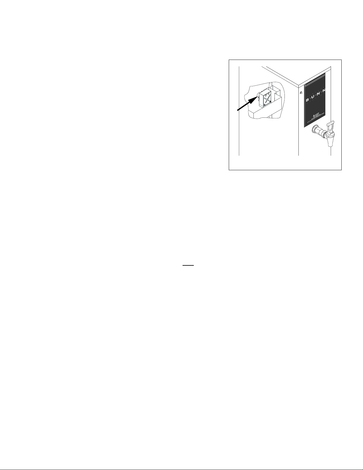
Thermostat
Location: The mechanical thermostat is located inside
the upper rear panel. To test the thermostat, access
will also be needed to the terminal block located inside
the bottom access panel.
Test Procedure:
1. Disconnect the dispenser from the power source.
2. Check the voltage across the black wire on the thermostat and the white or red wire at the terminal
block with a voltmeter. Connect the dispenser to
BLU/BLK to Limit Thermostat
BLK to Terminal Block
FIG. 10 THERMOSTAT WIRING
14
P1782
SERVICE (cont.)
Liquid Level Board
FIG. 11 LIQUID LEVEL BOARD
Location:
The liquid level board is located inside the lower
panel.
Test Procedure:
1. Disconnect the dispenser from the power source.
2. Remove the blue wire from terminal 1 and the pink
wire from terminal 4 of the circuit board.
3. Check the voltage across terminals 2 and 3 with a
voltmeter. Connect the dispenser to the power
source. Turn the thermostat knob to the “ON” position (fully clockwise). The indication must be:
a.) 100 to 120 volts ac for 100 to 120 volt models,
b.) 200 to 240 volts ac for 200 to 240 volt models,
c.) 230 volts ac for 230 volt models.
4. Disconnect the dispenser from the power source.
If voltage is present as described, proceed to #5.
If voltage is not present as described, refer to the wiring diagrams and check the wiring harness.
15

SERVICE (cont.)
Liquid Level Board (cont.)
15. Move the probe's flat end to the dispenser housing. The indication must be 0.
16. Move the probe's flat end away from the dispenser
housing. The indication should again be:
a.) 100 to 120 volts ac for 100 to 120 volt models,
b.) 200 to 240 volts ac for 200 to 240 volt models,
c.) 230 volts ac for 230 volt models.
17. Disconnect the dispenser from the power source.
If voltage is present as described, reinstall the probe,
the level control board and level probe are operating
properly.
If voltage is not present as described, check the pink
probe wire.
Removal and Replacement:
1. Remove all wires from the level control board.
2. Remove two #8-32 screws holding level control
board and mounting bracket to the component
bracket.
3. Install the new level control board and mounting
bracket to the component bracket.
4. Refer to FIG. 12 when reconnecting the wires.
BLU to Solenoid (T-1)
BLK to Overflow Safety Switch (T-2)
WHI to Terminal Block (T-3)
PNK to Level Probe (T-4)
P1784
FIG. 12 LIQUID LEVEL BOARD WIRING
16
10267 071900

SERVICE (cont.)
Contactor
FIG. 13 CONTACTOR
Location:
The contactor is located on the component
bracket inside the lower rear panel.
Test Procedures:
1. Disconnect the dispenser from the power source.
2. Disconnect the black wire from the contactor coil
to the limit thermostat and black wire from the red
wire on the main harness on two wire 240V models.
3. Check the voltage across the red wire and black
wire with a voltmeter. The indication must be:
a.) 240 volts ac for 240 volt models,
b.) 230 volts ac for 230 volt models.
4. Disconnect the dispenser from the power source.
If voltage is present as described, proceed to #5.
If voltage is not present as described refer to the Wiring Diagrams and check the wiring harness.
5. Check for continuity between the left and right terminals on the contactor coil.
If continuity is present as described, reconnect the
wires and proceed to #6
If continuity is not present as described, replace the
contactor.
6. Check the voltage across the upper left terminal
and the upper right terminal on the contactor with
a voltmeter. Connect the dispenser to the power
source. The indication must be:
a.) 240 volts ac for 240 volt models,
b.) 230 volts ac for 230 volt models.
7. Disconnect the dispenser from the power source.
If voltage is present as described, proceed to #8.
If voltage is not present as described, refer to the wiring diagrams and check the wiring harness.
8. Check for continuity across the terminals on the
left side of the contactor by manually closing the
contacts. Continuity must not present when the
contact is released.
9. Check for continuity across the terminals on the
right side of the contactor by manually closing the
contacts. Continuity must not be present when the
contact is released.
If continuity is present as described, the contactor is
operating properly.
If continuity is not present as described, replace the
17

SERVICE (cont.)
Contactor (cont.)
contactor.
Removal and Replacement:
1. Disconnect all the wires from the contactor.
2. Remove the two #8-32 screws securing the
contactor to the contactor mounting bracket, remove contactor and protective shield. Discard
RED to Terminal Block(L2)
contactor.
3. Install new contactor with shield between mounting bracket and contactor and secure with two #832 screws
4. Refer to Fig. 14 and reconnect the wires.
BLK to left Tank
Heater
RED to Right
Tank Heater
BLK to Terminal
Block (L1)
BLK to Limit
Thermostat
RED from Main Harness
FIG.14 CONTACTOR WIRING
P1725
18
10267 011599

WIRING DIAGRAMS
OPTIONAL
READY INDICATOR
BLK
SCHEMATIC WIRING DIAGRAM H5M
BLK
L1
BLK
BLK BLK
SW&
THERMOSTAT
THERMOSTAT
BLU/BLK
OVERFLOW
PROTECTION SWITCH
REDRED
120 VOLTS A C
2 WIRE
SINGLE PHASE
10243.0000D 1/99 © 1987 BUNN-O-MATIC CORPORATION
SCHEMATIC WIRING DIAGRAM H5M
L1
LIMIT
LIQUID
LEVEL
BOARD
BLK
4312
P
N
K
(PROBE)
GREEN
WHI
TANK HEATER
BLU WHI
SOL
WHI
GREEN
N
L2
BLK RED
OPTIONAL
READY INDICATOR
BLK
SW&
THERMOSTAT
BLK BLK
208 or 240 VOLTS A C
SINGLE PHASE
N.O. N.O.
RED
OVERFLOW
PROTECTION SWITCH
2 WIRE
BLU/BLK
REDRED
BLK
TANK HEATER
LIMIT
THERMOSTAT
BLK
LIQUID
LEVEL
BOARD
4312
P
N
K
(PROBE)
10262.0000C 1/99 © 1987 BUNN-O-MATIC CORPORATION
BLU
RED
BLK BLKBLK
K
SOL
RED
RED
RED
19
10267 011599

WIRING DIAGRAMS
SCHEMATIC WIRING DIAGRAM H5MA, 230V CE
L1
THERMAL
BLK RED-12BLK-12
BLK
BLK BLK
N.O. N.O.
SW&
THERMOSTAT
OVERFLOW
PROTECTION SWITCH
FUSE
THERMOSTAT
BLU/BLK
REDRED
N.C.
230 VOLTS A C
2 WIRE
TANK HEATER
LIMIT
LIQUID
LEVEL
BOARD
BLK
4312
BLU
P
N
K
(PROBE)
GREEN
THERMAL
FUSE
SOL
L2
RED
K
RED
RED
RED
SINGLE PHASE
10262.0001A 11/99 © 1999 BUNN-O-MATIC CORPORATION
20
10267 071900
 Loading...