

Page 1

INSTALLATION MANUAL
Description Rapid Power Part #
Adjustable Power Punch
Adjustable Power Punch 40602
7000 series: 7710, 7810
8000 series: 8100, 8200, 8300, 8400
8010 series: 8110, 8210, 8310, 8410
9050 series combines: 9550, 9650, 9750
Page 2

Introduction
IntroductIon:
Introduction: This instructions set is for the Power Punch power module and the Adjustable Power
Punch power module. These modules are specically made for John Deere tractors running a Bosch
fuel pump.
This instruction set only instructs how to install and operate the power module on the tractors in
the application chart. This product should not be used on any other John Deere product.
tABLE oF contEntS
INTRODUCTION ...............................................................................................PG. 1
BILL OF MATERIAL ...........................................................................................PG. 2
PRODUCT DESCRIPTIONS .................................................................................PG. 3
POWER PUNCH INSTALLATION .........................................................................PG. 4
OPERATING INSTRUCTIONS ...............................................................................PG 5
NOTES .............................................................................................................PG 6
IMPORTANT: Always remember to remove the module from the tractor or combine before taking it in for any
kind of service as the module may interfere with the service process for the tractor or combine. It is important that the
horsepower modification be accompanied by a pyrometer gauge to monitor Exhaust Gas Temperatures.
TROUBLESHOOTING:
If you have questions during the installation of this product,
please visit www.Bullydog.com/Product_Updates.php.
The latest version of these instructions can be found at the
same location. Please review the Troubleshooting section
on page 25 before calling technical support to cover most
common issues.Technical support is available by calling
866-bullydog (866-285-5936).
1
Page 3
2.
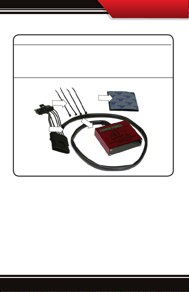
Bill of Materials
BILL OF MATERIALS
1. Power Punch Module
2. Wiring Harness
3. Velcro Pad
4. Four Zip Ties
3.
4.
1.
2
Page 4

Product Description
Product dEScrIPtIon:
The product is made up of three different parts, the module box, the wiring harness which
includes the plugs, and the flip switch. Things to note on each part:
THE MODULE BOX:
The module box holds the guts of the product, the circuit board, it
is very important that when this module gets mounted during installation that it is away from extreme heat and that it is not prone
to a lot of moisture.
THE WIRING HARNESS:
A the end of the wiring harness is two plugs, one male and one female
plug. Also notice that the plugs are identical to the stock plugs coming
o of the fuel pump on the tractor, these plugs are made specically
to work with the John Deere tractor with no additional modication
necessary.
The Flip Switch (Only on Adjustable Power Punch):
Flip the switch back and fourth, notice it is a simple
toggle switch that has three positions: one 30%,
one 20%, and one at 10%. The ip switch does
not have any stock position so if the user wishes to
operate their tractor or combine at stock hp levels
they must remove the power module from the
tractor.
3
Page 5

Installation
InStALLAtIon InStructIonS:
1. Locate the fuel pump plug under the hood and on top of the fuel pump, it is not necessary to remove the hood
for the install. The fuel pump and plug are located on the left side of the tractor if you are facing the front of the
tractor. Identify the plug by looking for a six prong plug with a green bushing, identical to the Bully Dog plugs
on the Power Punch power module.
2. Disconnect the stock female plug from the stock male plug.
3. Connect the Bully Dog female plug up to the stock male plug, which is stationary on the tractor, push the connector
in until it snaps. Now connect the stock female plug to the male Bully Dog Plug.
4. Mount the module box in a safe location using the velcro pad. Use the zip ties to secure the wires away from any
extreme heat and moving parts.
5. Run the ip switch into a location that is easily accessible for the operator, once the module is installed the operator
can change power levels.
4
Page 6

Operating Instructions
oPErAtIng InStructIonS:
1. After completing the installation of the module, set
the toggle to 10% and turn the tractor or combine
on to test if the module is working. If the tractor
starts then the module is working. If the tractor does
not turn on then check all of the connections on the
install to be sure that they are secure and then attempt to start the tractor again.
2. While operating the trac tor with the three new settings the operator can accomplish a few dierent
things that will be seen as a benet to the operator
and the owner:
*Only on Adjustable Power Punch
RECOMMENDED MODULE USES
SAVE FUEL:
The operator of the tractor with more power can use the power to grab a higher gear and they can maintain the same speed in the higher gear or just go a little quicker. The operator will notice that it takes less
throttle to accomplish the same speed as with stock horsepower levels, with the module installed.
MOVE QUICKER:
The operator as long as they are pulling the same implements in comparison can move at a higher rate of
speed therefore allowing them to nish jobs quicker.
PULL HEAVIER IMPLIMENTS:
The power module increases horsepower dramatically allowing smaller tractors to pull larger implements.
When pulling large impliments with a small tractor it is important to have a pyrometer which monitors
exhaust gas temperatures.
5
Page 7

Notes
6
Page 8

Doc.# 40602-99 V2.0
Check out more of our ADRENALINE PUMPING products!
Downloaders
Intake Systems
Exhaust SystemsTriple Dog GT
®
Free Technical Support at:
866-bullydog (866-285-5936)
See More at: bullydog.com
 Loading...