

Page 1

INSTALLATION MANUAL
Applications Rapid Flow Part Number
Ford 3.5L F150 ‘11 51202
Not legal for sale or use in California on pollution-controlled vehicles.
Page 2

1
TROUBLESHOOTING:
Technical support is available by calling 1-940-783-9915.
Tech support by phone is available Monday-Friday 8am5pm Mountain Standard Time.
Table of Contents
TABLE OF CONTENTS
INTRODUCTION ..........................................................................................................PG. 1
PARTS INCLUDED ........................................................................................................PG. 2
PARTS DESCRIPTION ..............................................................................................PGS. 3-5
INSTALLATION ....................................................................................................PGS. 6-14
INSTALLATION OVERVIEW....................................................................................PG. 6
REMOVING THE STOCK INTAKE ........................................................................PGS. 7-9
INTAKE INSTALLATION PREP ....................................................................... PGS. 10-11
INTAKE INSTALLATION ................................................................................ PGS. 12-14
FILTER MAINTENANCE ..............................................................................................PG. 15
PREFILTERS .............................................................................................................. PG. 16
TROUBLE SHOOTING .................................................................................................PG. 17
INTRODUCTION
This instruction set outlines the description and installation of the Rapid Flow Cold Air Intake for the
Ford 3.5L F 150 Eco Boost 2011. Installation of this intake takes about 20 minutes and requires only
basic tools.
For additional questions or product information visit our website www.bullydog.com or call Bully Dog
technical support at 1-940-783-9915.
Page 3
2
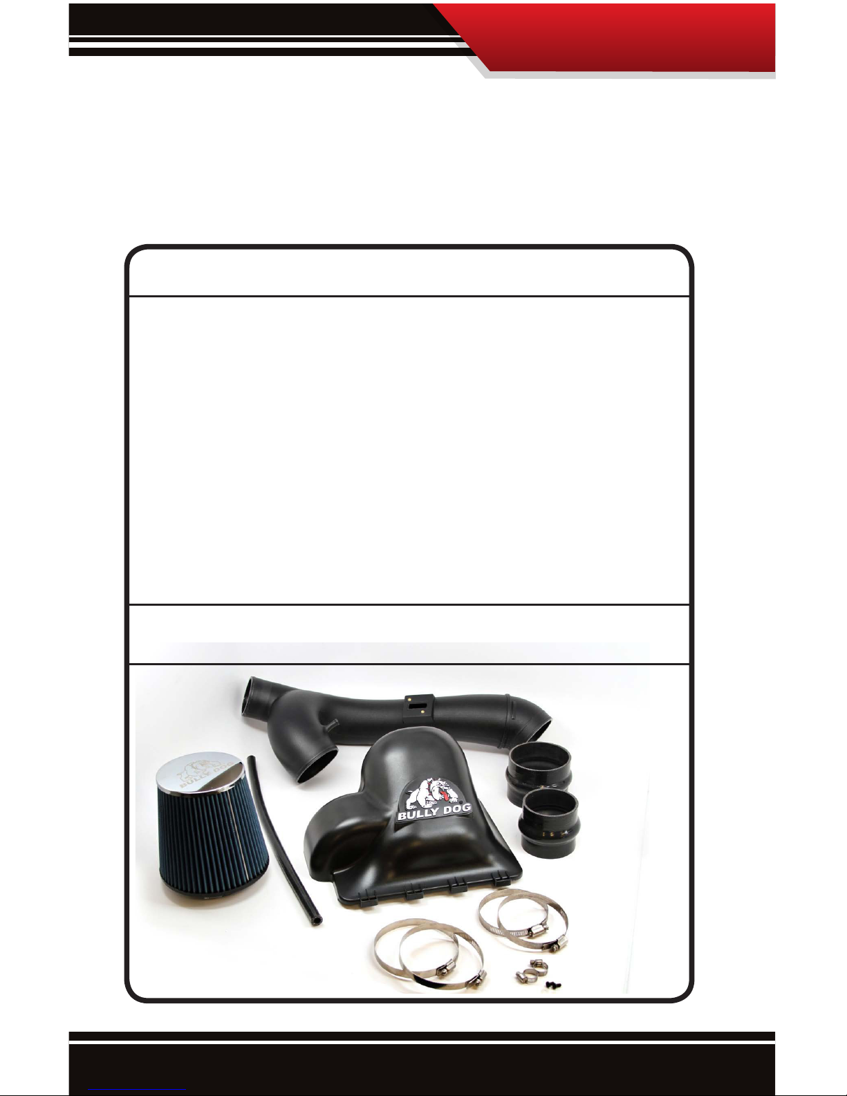
Parts Included
Parts Included and Tools Needed:
This section displays the parts included in the package and the tools needed to properly
install the system.
Parts Included
Air Intake Enclosure Lid ........................................................................... 51200-1
Air Intake Tube w/maf boost tube ...........................................................51202-3
Bully Dog Logo name plate .....................................................................5-50002
Silicone 100 mm ID x 76mm 3ply ............................................................ 51202-5
Silicone 80mm ID x 76 mm with Hump 3ply............................................ 51202-6
Silicone tube 9.5 mm ID x 500 mm 2 ply ................................................. 51202-7
Worm drive 4.5” max or 114mm .............................................................. 53252-7
Worm drive 4” max or 102mm ................................................................. 51105-7
# 6 worm drive clamp ............................................................................. 4-28201
Air lter assembly ................................................................................... 224900
Literature Pac .......................................................................................... LITPAC
Screw 8-32 x 3/8” blk oxide pan head ...................................................... 54100-94
T20 Tamper Proof Torx Bit ........................................................................ 229120
Tools needed
Flat Head Screwdriver Phillips Screwdriver Bit Driver
13mm Socket and Wrench (optional)
Page 4

3
Parts Description:
This section describes each part and any special features of each part that need to be noted
to assist with installation. All parts will be referred to during installation by the names used
in this section.
The Lid: This simple to install lid replaces the stock lid and conceals and protects the high
ow air lter that comes with the kit. It also has an extra air ow port to provide more cold
air from the front of the vehicle for a slight charge eect.
Parts Description
Page 5
4
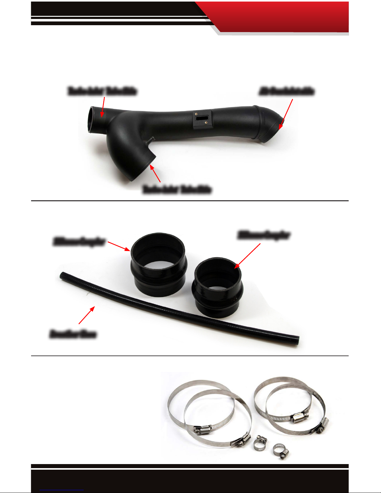
MAF Intake Tube: The intake tube installs between the air box and the turbo inlet tubes.
Silicon Tubing: High quality 3 ply silicon tubing.
Band Clamps: Connects and holds all tubing in place.
Air Box Inlet side
Silicone Coupler
Breather Hose
Silicone Coupler
Turbo Inlet Tube Side
Turbo Inlet Tube Side
Parts Description
Page 6
5
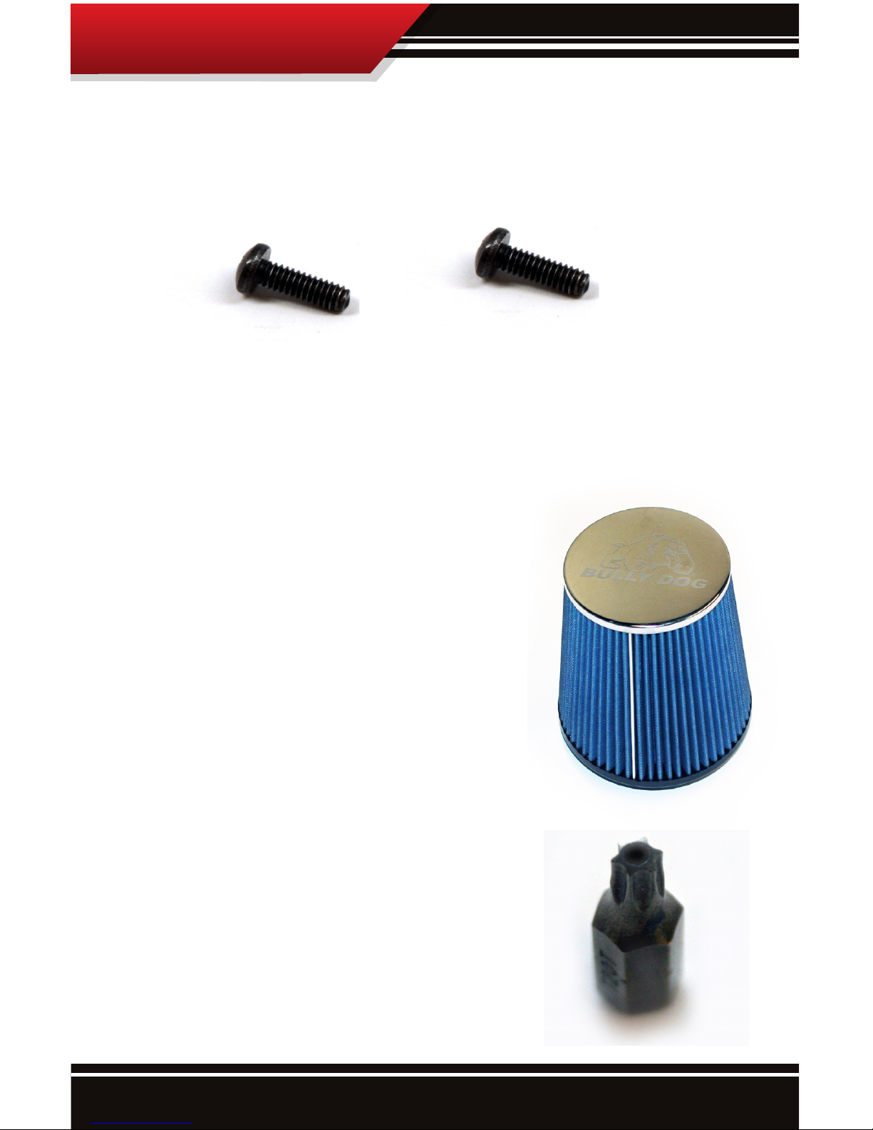
Stainless Black Oxide Screws: The two Phillips style stainless black oxide screws are
included with the kit to secure the MAF sensor to the air intake tube.
Air Filter and Clamp: The air lter included is an ISO
5011 certied eight layer oil lter. The air lter is secured
onto the end of the air intake tube using the lter clamp
and a at-head screwdriver.
Security Torx Bit: This bit is included for convenience;
the mass air ow sensor is attached to the stock intake
tube using security Torx screws. If this bit is lost it can be
ordered.
Parts Description
Page 7

6
Installation Overview:
Installation is very simple, it is separated into three parts: Removing the Stock Intake,
Preparing the Rapid Flow Cold Air Intake for installation, and Installing the system. The complete installation of the Rapid Flow Cold Air Intake system should total about 20 minutes.
The assembly diagram below shows how the parts of the intake t together in sequence.
Stock Intake Overview Diagram: The stock intake can be seen in the picture below. Notice the important parts of the stock air intake that are labeled in the diagram below. These
items are referred to throughout these instructions.
Stock Intake Overview
Mass Air Flow Sensor
OEM intake tube
Stock Intake Lid
Installation Overview
Page 8

7
Stock Intake Removal:
1. Unplug the Mass Air Flow sensor: to do so properly rst pull the red tab located on the
bottom side of the sensor outward to release the locking mechanism. Disconnect the sensor plug from the mounted sensor.
2. Loosen both band clamps on the stock tube where the tube splits
Stock Intake Removal
band clamp
band clamp
Page 9

8
3. Remove the breather hose from the tting. A zip tie may need to be cut for removal.
4. Loosen the latches holding the stock lid on. Separate the stock turbo inlet tubes from the
coupler
Stock Intake Removal
Page 10

9
Stock Intake Removal
5. Remove the entire assembly together.
6. Remove the stock lter.
Page 11

10
Intake Install Prep
Intake Installation Prep
1. Snap Bully Dog tube in the Bully Dog lid, attach the lter and tighten the band clamp.
2. Remove the stock MAF sensor with the provided T20 security bit and install the MAF sensor onto the Bully Dog tube with the provided phillip screws.
DO NOT USE STOCK SCREWS
Page 12

11
Intake Install Prep
3. Slide silicon couplers and clamps onto the appropriate ends of the Bully Dog tube.
Page 13

12
Intake Installation
2. Secure stock latches onto the Bully Dog lid
Intake Installation
1. Guide the Bully Dog lid/tube assembly into the engine bay. Slide the tabs on the Bully
Dog lid into the stock box slots.
Page 14

13
Intake Installation
3. Position the tube and slide the silicone couplers onto the stock tube. Adjust for tment
then tighten clamps.
4. Install the silicon breather hose with clamps onto the Bully Dog tube and stock connection. Tighten the clamps.
Page 15

14
Intake Installation
4. Reconnect MAF sensor plug
Page 16

15
Filter Maintenance:
The intake system should be cleaned at least once every three months; in dusty climates the lter
should be cleaned more often. Use a prelter to extend time between cleaning. Cleaning the intake
is a two part process, the rst part of the process involves the physical cleaning of the lter with soap
and water and the second part involves oiling the lter. To properly clean the lter, a Bully Dog cleaning kit should be used. Cleaning kits are available at any Bully Dog
dealer.
PART 1, CLEANING THE FILTER:
1. Remove lter from lter housing. Clean the lter housing if
necessary.
2. Begin the cleaning process by ridding the lter of any dirt by
lightly tapping it. Then brush away any loose particles with a
soft-bristle brush. This step can usually be avoided with the
use of a prelter.
3. Spray cleaner generously over entire lter and let soak for
10 minutes.
4. Thoroughly rinse the lter with regular tap water (avoid
high-pressure hoses). Flush from the inside out or clean side
to the dirty side to prevent dirt from entering the lter.
5. Let the lter air dry before oiling, do not use any method to speed up the drying process. Using
a blow dryer or compressed air can cause the lter to disgure which would then allow particles
to pass through the lter.
PART 2, OILING THE FILTER:
1. Apply a small amount of oil to the soft bristle brush and spread the oil over the lter. Be sure to
apply a small amount of force so not to damage the lter element.
2. Continue applying oil to the lter using a soft bristle brush until the entire lter is covered in an
even amount of oil, just enough to give the lter a solid blue color. Apply enough oil to make the
lter a solid and uniform blue, but do not go beyond that.
3. Allow oil to sit for 20 minutes. Re-oil any dry spots that appear. Do not oil lter excessively. Exces-
sive oiling can cause damage to intake sensors.
Filter Maintenance
Part # 229000
Page 17

16
AIR FILTER PREFILTER
• Extend Time Between Cleanings
• Hydrophobic Material Repels Water
• Protects Cone Filter from Large Debris
• Maintains Filter Airflow Between Cleanings
Bully Dog PreFilter (Part # 51200-8 for your intake)
The time between scheduled lter maintenance can be extended. Using a prelter will prevent
all large debris from getting into the ribs of the lter. When using the prelter, only ne dust
particles make it through the prelter and onto the exterior of the lter. Thus when using a prelter,
scheduled cleaning easy much easier and lter life is positively eected.
Prelter
Page 18

17
Trouble Shooting
The OEM air intake sensor does not t in the Bully Dog air intake tube
because it is a dierent shape.
Check the year of the vehicle, the 2011 and 2012 Ford F150 3.5L ecoboost have dierent air intake
sensors which are dramatically dierent in shape and size. Bully Dog part number 51202 only ts the
2011 F150 Ecoboost.
Page 19

18
Page 20

Clothing
Triple Dog GT Prelter
Check out more of our ADRENALIN PUMPING products!
Cleaning Kits
Doc.# 51202 V3.0
Free Technical Support at: 1-940-783-9915
See More at: bullydog.com
GT Diesel is not legal for sale or use in California on pollution-controlled vehicles.
 Loading...