

Page 1

INSTRUCTIONS
AND
PARTS MANUAL
STEPPER MODULE
BUG-9870 120 VAC
BUG-9872 240 VAC
BUG-9874 42 VAC
Please record your equipment identication information below for future reference. This information can be
found on your machine nameplate.
Model Number:
Serial Number:
Date of Purchase:
Whenever you request replacement parts or information on this equipment, always supply the information
you have recorded above.
LIT-STPR-IPM-0415
Bug-O Systems is guided by honesty, integrity and
ethics in service to our customers and in all we do.
A DIVISION OF WELD TOOLING CORPORATION
280 TECHNOLOGY DRIVE CANONSBURG, PENNSYLVANIA 15317-9564 USA
PHONE: 412-331-1776 http://www.bugo.com FAX: 412-331- 0383
Page 2
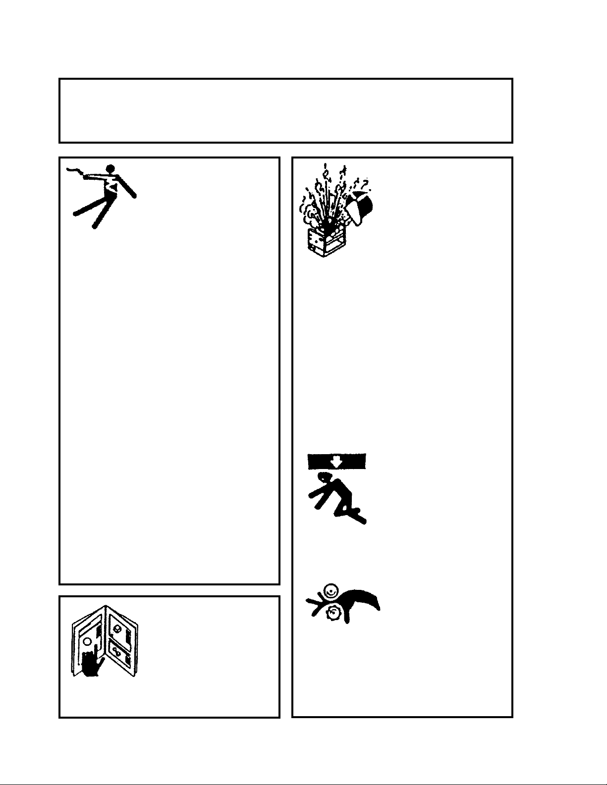
SAFETY
PROTECT YOURSELF AND OTHERS FROM SERIOUS INJURY OR DEATH.
KEEP CHILDREN AWAY. BE SURE THAT ALL INSTALLATION, OPERATION,
MAINTENANCE AND REPAIR PROCEDURES ARE PERFORMED ONLY BY
ELECTRIC SHOCK can kill.
1) The equipment is not waterproof.
Using the unit in a wet environ-
ment may result in serious injury.
Do not touch equipment when wet
or standing in a wet location.
2) The unused connectors have
power on them. Always keep the
unused connectors covered with
the supplied protective panels.
Operation of the machine without
the protective panels may result in
injury.
QUALIFIED INDIVIDUALS.
EQUIPMENT DAMAGE
POSSIBLE.
1) Do not plug in the power cord without
rstverifyingtheequipmentisOFF
and the cord input voltage is the same
as required by the machine or serious
damage may result.
2) Always verity both the pinion and
wheels are fully engaged before apply ing power or equipment damage may
occur.
3) Never open the equipment without
rstunpluggingthepowercordor
serious injury may result.
4) Verify the customer-supplied power
connections are made in accordance
with all applicable local and national
electrical safety codes. If none exist,
use International Electric Code (IEC)
950.
5) Never remove or bypass the equip ment power cord ground. Verify the
equipment is grounded in accor dance with all applicable local and
national electrical safety codes. If
none exist, use International Electric
Code (IEC) 950.
READ INSTRUCTIONS.
3) Do not leave the equipment
unattended.
4) Remove from the work site and store in
a safe location when not in use.
FALLING EQUIPMENT
can cause serious
personal injury and
equipment damage.
Faultyorcarelessuserinstallationis
possible. As a result, never stand or
walk underneath equipment.
MOVING PARTS can
cause serious injury.
1) Never try to stop the pinion from mov ing except by removing power or by
using the STOP control.
Read the instruction manual before
installing and using the equipment.
2
2) Do not remove any protective panels,
covers or guards and operate equip ment.
Page 3

HIGH FREQUENCY WARNINGS
SPECIAL PRECAUTIONS ARE REQUIRED WHEN USING PLASMA,
TIG OR ANY WELDING PROCESS THAT USES HIGH FREQUENCY
TO STRIKE AN ARC.
WARNING: HIGH FREQUENCY CAN EFFECT MACHINE
OPERATION AND THEREFORE, WELD QUALITY.
Read the precautions below before installing and using the equipment.
PRECAUTIONS:
1) Some plasma or welding cables are strong sources of high frequency interference.
NEVER lay a plasma or welding cable across the controls of the machine.
2) Always physically separate the plasma or welding cable leads from the
machinecables.Forexample,theplasmaorweldingcableleadsshould
NEVER be bundled with a pendant cable or the machine power cord. Maximize
the separation between any machine cables and the plasma or welding cables.
3) Strictlyfollowthegroundingproceduresspeciedfortheplasmaorwelding
unit. NOTE: Some plasma and welding units produce exceptionally large
amounts of high frequency noise. They may require a grounding rod be
driven into the earth within six feet (2 meters) of the plasma or welding unit to
become compatible with an automatic cutting or welding process.
4) If the high frequency is produced using a spark gap, adjust the points so the
gap is as small as possible. The larger the gap, the higher the voltage and
the higher the interference.
5) Some plasma or welding units will inject high frequency interference into the
AC power line. Use separate power line branches whenever possible to power
the plasma or welding source and the machine. Do not plug them into the
same outlet box.
6) High frequency noise may enter the machine through the plasma or welding
supply remote contactor leads. Some plasma and welding sources can
produce noise spikes of up to several thousand volts. These sources are not
compatible with automated cutting and welding equipment. It is recommended
that the remote contactor leads on these plasma or welding sources not be
connected to the machine. An alternate solution is to purchase a separate
remote contactor isolation box.
3
Page 4

STEPPER MODULE
BUG-9870 120 VAC
BUG-9872 240 VAC
BUG-9874 42 VAC
INSTRUCTIONS AND PARTS MANUAL
TABLE OF CONTENTS
PAGE
5.............. Introduction / Technical Data / Items Supplied / Specications
6.............. Setup
6.............. BUG-9875 Stepper Module Switch Assembly / Parts List / Wiring Diagram
7.............. Operating Instructions
8.............. BUG-987X Stepper Module / Exploded View
9.............. BUG-987X Stepper Module / Parts List
10............ Wiring Diagram / Electrical Component Chart
11 ............ Troubleshooting
12............ Warranty
4
Page 5

INTRODUCTION
The BUG-O Stepper Module is an adjustable, timed output, power control, that is typically used to
overlay the surface of a shaft mounted in a lathe or on turning rolls where a weld bead is continuously
laid down, side by side, with each revolution.
Advance of the weld bead is a function of how long the BUG-O, or other tractor, is powered by the
Stepper Module when limit switch is activated and the speed of the BUG-O.
TECHNICAL DATA
Voltages: BUG-9870 120/VAC/50-60Hz/1Ph
BUG-9872 240/VAC/50-60Hz/1Ph
BUG-9874 42/VAC/50-60Hz/1Ph
Output Current
Capacity: 3.25 AMPs
Net Weight: 3.5 lbs. (1.5 kg)
L W H
Dimensions: 5.75" x 5.75" x 3.5"
(147 mm x 147 mm x 89.3 mm)
Timer range: 0.1 to 9.9 seconds
ITEMS SUPPLIED
Complete Stepper Module Assembly including one (1) BUG-9875 Stepper Module Switch Assembly
with 8' (2.4 m) long cable.
SPECIFICATIONS
Set time is displayed digitally as #.# and ranged from a minimum setting of 0.1 to a maximum setting of
9.9 seconds.
The Limit Stitch must be securely mounted in-line with a trip mechanism (such as a weld bead, screw
head or ag) that will actuate the limit switch once per revolution of the part. This trip mechanism
actuates the limit stitch and powers the BUG-O to move. Based on the Stepper Module’s set time and
the speed setting on the BUG-O tractor, the BUG-O will move and stop, advancing the weld. Welding
does not stop when the BUG-O moves.
This sequence continues until the operator manually stops the BUG-O and/or the welding process.
NOTE: Limit Switch must be “released” to reset for the next sequence. If the limit switch is not
“released”, the BUG-O will not advance. Check setup and conrm the limit switch resets.
5
Page 6

SETUP
Mount Stepper module to the BUG-O tractor using two (2) ¼-20 x screws, hex head, socket head or
cap screws (not supplied), using the mounting holes on the BUG-O carriage.
Mount Limit Switch to work where a trip mechanism will actuate the limit switch with each revolution of
the work piece. “Trip” can be a screw head, ag, spot weld or any other item that will activate the limit
switch / BUG-O. Mounting brackets used to install the Limit Switch are of your own make or purchase
that is appropriate to the specic application.
Plug power cord of Stepper Module into main power supply.
BUG-9875 STEPPER MODULE SWITCH ASSEMBLY / PARTS LIST / WIRING DIAGRAM
PART NO. QTY DESCRIPTION
900-4-001 96" Power Cord, SJO 18/2-250,
300V
BUG-1417 1 Cross Roller Plunger Actuated
BUG-9217-P 1 Cord Grip
BUG-9857 1 Cable Connector, 2-7, M
6
Page 7

OPERATING INSTRUCTIONS
Now that limit switch is mounted, screw the amphenol end of the limit switch cable into the amphenol
connector on the Stepper Module. The Stepper Module is mounted to the BUG-O tractor, BUG-O tractor is plugged into the power cable of Stepper Module. Input power is connected to Stepper Module. It
is time to test set-up.
Turn timer adjustment to display 3 seconds (3.0), this is an arbitrary value for this testing. Without turning your lathe or turning rolls on, manually trigger the limit switch, make sure to completely release the
limit switch (see “NOTE” below). The BUG-O should move until the relay completes the timed cycle,
then stops. Now, trigger the limit switch a second time, the BUG-O should move the same distance and
stop. Timer adjustment can now be set to desired time.
Timer Adjustment
Display
NOTE: If the limit switch is not completely released, the
timer will not reset. If not completely released activating
the limit switch will not result in the BUG-O moving.
Make certain that the limit switch mount will allow the
limit switch to completely reset. Revise the mounting or
adjust the limit so that the limit switch resets.
7
Page 8

BUG-987X STEPPER MODULE / EXPLODED VIEW
7
1
2
14
31
27
28
32
9
21
23
29
30
4
33
11
24
30
8
23
17
18
34
19
5
3
13
15
16
22
11
26
20
29
22
35
25
10
36
8
Page 9

BUG-987X STEPPER MODULE / PARTS LIST
ITEM QTY PART NO. DESCRIPTION
1 18" 900-4-019 16/3 SJTOW 300V, Pvc
2 1 BUG-2924 Reset Seal, Transparent
3 1 BUG-2929 Circuit Breaker 4 A
4 1 BUG-9216 Cord Grip
5 1 BUG-9453 V-Lock Power Inlet
6* 1 See pg. 10 V-Lock Power Cord
7 1 See pg. 10 Receptacle
8 1 BUG-9856 Panel Connector, 2-T, F
9 1 BUG-1338 Nameplate
10 1 BUG-9866 Stepper Base Plate
11 1 BUG-9871 Stepper Mod Enclosure
12 1 BUG-9875 Stepper Module Switch Assembly
13 4 FAS-0104 4-40 x 3/8 Pan Head, Black
14 2 FAS-0235 Rnd Hd Scr 10-24 x 1/2
15 1 MDS-1011 Display Bezel
16 1 MDS-1013 Display Filter
17 1 MDS-1018 Knob Straight Knurl, Black
18 1 MDS-1046 Knob Seal (Black)
19 1 MDS-1052 10K Potentiometer
20 4 MET-0143-SS Pan Hd Phil Scr M3 x 10
21 1 MET-0559-SS Soc Hd Cap Scr M4 x 20
22 6 MET-0943 Flt Hd Soc M3 x 10
23 6 MET-1340-SS M3 Hex Nut
24 1 MET-1350-SS M4 Hex Nut
25 1 See Chart Digital Stepper Module
26 4 SCF-1001 4-40 Self-Clinching Nut
27 2 WAS-0230 #10 Sae Flat Washer
28 2 Was-0232 #10 Split Lock Washer
29 6 WAS-5540-SS M3 Washer
30 6 WAS-5541-SS M3 Lock Washer
31 1 WAS-5550-SS M4 Washer
32 1 WAS-5551-SS M4 Lock Washer
33 2 See Chart Voltage Label
34 1 BUG-2005 Label, Bug-O
35 2 FAS-0559 Soc Hd Cap 1/4- 20 x 1
36 2
FAS-1351 Hex Nut 1/4- 20
* = Not Shown
9
Page 10

BUG-987X STEPPER MODULE / WIRING DIAGRAM
ELECTRICAL COMPONENT CHART
ITEM* DESCRIPTION BUG-9870 120
6 V-Lock Power Cord BUG-9454 BUG-9454-240 BUG-9454-42
7 Receptacle BUG-2847 BUG-9594 BUG-2847
25 Digital Stepper Module PCB-1219 PCB-1219 PCB-1219-42
33 Voltage Label BUG-9234 BUG-9233 BUG-9492
3 Circuit Breaker BUG-2929
5 V-Lock Power Inlet
8 Panel Connector BUG-9856
12 Limit Switch in BUG-9875
Stepper Module Switch Assembly
19 Potentiometer MDS-1052
* See Exploded View for Item Number relations
10
VAC
BUG-9872
240 VAC
BUG-9453
BUG-9454
BUG-1417
BUG-9874
42 VAC
Page 11

TROUBLESHOOTING
PROBLEM
Unit will not
move.
Weld beads
are spaced
too far
apart.
POSSIBLE CAUSE TEST BASE SYSTEM TEST PROCEDURE / REMEDY
Mechanical checks: A1
A2
A3
Electrical checks: B1
B2
B3
B4
B5
Stepper Module checks: C1
C2
Tractor speed
Timer settingD1D2
Make certain that there are no obstructions preventing
movement.
Make certain that wheels of carriage are properly installed
on BUG-O Rail.
Make certain that Pinion and Rack are properly engaged
and locked in place.
Proper Power is supplied to BUG-O.
BUG-O is turned “ON.”
BUG-O direction switch is set to move and in proper
direction.
Display on Stepper Module is illuminated.
Reset BUG-O Circuit Breaker.
Make certain that “FLAG” is actuating limit switch and that
limit switch has room to reset.
With welder off, turn speed of BUG-O to mid range and set
Timer to display 1.0 (1 second) and activate limit switch.
Slow speed of BUG-O.
Reduce Timer setting. This bring beads closer together.
Weld bead
is not
spaced far
enough
apart.
Tractor speed
Timer settingE1E2
Increase speed of BUG-O.
Increase Timer setting. This will move weld bead further.
11
Page 12

WARRANTY
Model _____________________________
Limited 3-Year Warranty
For a period ending one (1) year from the date of invoice, Manufacturer warrants that any new machine or part
is free from defects in materials and workmanship and Manufacturer agrees to repair or replace at its option, any
defective part or machine. HOWEVER, if the invoiced customer registers the Product Warranty by returning the
Warranty Registration Card supplied with the product within 90 days of the invoice date, or by registering on-line at
www.bugo.com, Manufacturer will extend the warranty period an additional two (2) years which will provide three
(3) total years from the date of original invoice to customer. This warranty does not apply to machines which, after
Manufacture’s inspection are determined by Manufacturer to have been damaged due to neglect, abuse, overloading, accident or improper usage. All shipping and handling charges will be paid by the customer.
The foregoing express warranty is exclusive and Manufacturer makes no representation or warranty (either express or implied) other than as set forth expressly in the preceding sentence. Specifically, Manufacturer makes
no express or implied warranty of merchantability or fitness for any particular purpose with respect to any goods.
Manufacturer shall not be subject to any other obligations or liabilities whatsoever with respect to machines or parts
furnished by Manufacturer.
Manufacturer shall not in any event be liable to Distributor or any customer for any loss of profits, incidental or consequential damages or special damages of any kind. Distributor’s or customer’s sole and exclusive remedy against
Manufacturer for any breach of warranty, negligence, strict liability or any other claim relating to goods delivered
pursuant hereto shall be for repair or replacement (at Manufacturer’s option) of the machines or parts affected by
such breach.
Serial No. __________________________
Date Purchased: ____________________
Where Purchased:___________________
Distributor’s Warranty:
In no event shall Manufacturer be liable to Distributor or to any customer thereof for any warranties, representations or promises, express or implied, extended by Distributor without the advance written consent of Manufacturer,
including but not limited to any and all warranties of merchantability or fitness for a particular purpose and all warranties, representations or promises which exceed or are different from the express limited warranty set forth above.
Distributor agrees to indemnify and hold Manufacturer harmless from any claim by a customer based upon any
express or implied warranty by Distributor which exceeds or differs from Manufacturer’s express limited warranty
set forth above.
HOW TO OBTAIN SERVICE:
If you think this machine is not operating properly, re-read the instruction manual carefully, then call your
Authorized BUG-O dealer/distributor. If they cannot give you the necessary service, write or phone us to
tell us exactly what difculty you have experienced. BE SURE to mention the MODEL and SERIAL numbers.
12
 Loading...