

www.buffalotech.com/wireless
User Manual
Wireless
Cable/DSL Router-G
WBR2-G54

Introduction
1.1 AirStation Broadband Router Base Station (WBR2-G54)
Welcome to AirStation, the easy way to ultra fast wireless networking.
This manual, which describes the most common confi gurations, introduces you to the AirStation
Cable/DSL Router, and will help you connect to your network quickly.
The WBR2-G54 router, is a wireless 4-port router small/medium business (SMB) network device
that complies with the 2.4GHz IEEE 802.11g standard specifi cation on wireless LANs. The WBR2G54 supports enhanced built-in NAT/SPI fi rewall functions and is used as a multi-functional router/
link between wired and wireless LAN computers.
Summary of the AirStation WBR2-G54 features:
• Wi-Fi™ (Wireless Fidelity) certifi ed by the Wi-Fi Alliance as an 802.11b/g device. AirStation will
communicate with other IEEE 802.11b/g/Wi-Fi compliant wireless LAN products.
• Support for Wi-Fi Protected Access™ (WPA), 802.1x, TKIP, AES, and WEP.
• Automatic Transmit Rate Select mechanism transmits at speeds of 54, 36, 24, 11, 5.5, 2 and 1
Mbps.
• Supports Frame Bursting for enhanced performance.
• DHCP client/server function.
• Auto roaming, supports seamless roaming over multiple channels.
• VPN pass-through, for secure communications.
• Packet Filtering for eliminating unwanted communications.
2

Introduction
• SOHO/SMB routing and fi rewall functions provide a safer private networking environment, including support for MS NetMeeting and MSN-Messenger.
• Additional SPI Firewall Functions - DMZ, intrusion detection and notifi cation
• Syslog transmits some or all system activities to a central Syslog server.
• Extended range, with optional add-on antennas or WDS (Wireless Distribution System).
• Auto Media Dependent Interface/Crossover (MDI/X) port, allows connection by standard and
crossover CAT5 cables.
• Supports Universal Plug and Play (UPnP).
• Buffalo’s AOSS System for easy, secure wireless client confi guration.
1.2 AirStation Wireless Network Features
• Enhanced security features:
- SPI Firewall and DMZ zone functions to prevent unknown intruders.
- Intrusion Detector Firewall (NAT) with a pop-up or email alert warning unwanted attacks.
- Dynamic packet fi ltering.
- WPA, 802.1x, TKIP, AES, and WEP.
- VPN (IPSec, PPTP and L2TP) pass-through
- Packet monitoring and fi ltering by MAC address, IP address and port.
- PPPoE support
3

Introduction
- WDS support
• Buffalo’s easy web interface confi guration
• Broadband router static and dynamic routing methods between WAN and LAN based on updated
routing tables. An economical way to bridge multiple networks.
• Optional external antennas for boosting range and signal quality.
• Buffalo’s AOSS System for easy, secure wireless client confi guration.
1.3 Home Networking 1
For the future home entertainment applications that carry hard drives for storing hundreds of titles,
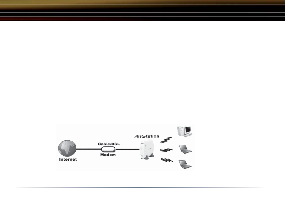
IEEE 802.11g can transmit three channels of CD-quality voice to every room in the home simultaneously. Buffalo AirStation wireless access points enable sharing broadband by simply connecting
the AirStation to a DSL or CATV modem to:
• Share fi les and printers
• Access and share the Internet
• Share media fi les
1.4 SOHO/SMB Networking
4
Introduction
With high-speed DSL or CATV connections readily available, many users can work effectively from
a home offi ce, connected securely to a corporate network. Buffalo’s solutions are ideal for home
networks that require secure, high-speed access to the corporate LAN. Tools that play an integral
part in Buffalo’s solutions include VPN connectivity for secure access to corporate resources, which
enable the remote employee to handle information from clients or coworkers as if they were in the
offi ce. Connect the Buffalo AirStation Broadband router AP to a CATV or DSL modem in order to:
•Share broadband access
•Share fi les and printers
•Bridge between multiple networks and multiple computer platforms
•Provide easy and secure access to home or company networks from remote locations
1.5 System Requirements
Figure 1.4
SOHO/SMB
Networking
5

Introduction
• Broadband (High-Speed) Internet connection or existing Local area connection
• Any Wi-Fi (wireless) compatible computer with a Web Browser Internet Explorer or Netscape 4.5
or later. (Safari 1.0 is supported with Macintosh OS X.2)
1.6 AirStation WBR2-G54 Package Contents
The AirStation WBR2-G54 package consists of the following items.
1. WBR2-G54 Base Station
2. AC adapter and power cable
3. CAT5 LAN cable
4. Utility CD with Manual
5. Quick Setup Guides
6. Warranty Statement
6

The LAN or Wired MAC address is
the default ESS-ID (SSID) of the
AirStation. The LAN MAC address
is clearly labeled on the back of the
AirStation.
1.7 Product Views
Power - Lit when the device is powered on.
Wireless - Lit when the wireless radio is on. Flashes when
wireless traffi c is present.
WAN - Lit when connection to Cable/DSL modem is present.
Flashes when internet traffi c is present.
Diag - Flashes red when performing diagnostic functions.
AOSS - Flashes when in AOSS mode.
Ethernet - 1, 2, 3, or 4 lit when ethernet clients are connected.
Flashes when ethernet traffi c is present.
Introduction
7

Introduction
1.8 About the AirStation CD
The AirStation does not require any software to be installed on your computer for confi guration.
The AirStation CD contains client drivers for Buffalo Wireless Adapters (i.e. Notebook Adapter and
Desktop PCI Adapter) and the AirStation documentation.
Prior to copying or installing any software, please read the Software License Agreement “license.
txt”, located in the root folder of the CD. By installing, copying or using the AirStation software, you
are consenting to the terms of this agreement. If you do not agree to all of the terms of the Software
License Agreement, do not download, copy or install the AirStation software.
It is the policy of Buffalo Technology to improve products as new technology, components, software
and fi rmware become available.
Please consult the AirStation wireless website (http://www.buffalotech.com/wireless) to download
and install the latest fi rmware for your product.
8
Installation / Setup
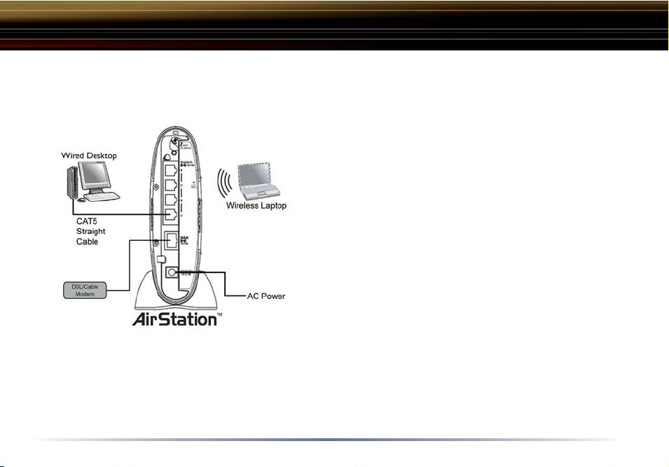
Follow these simple steps to connect the AirStation to your Broadband Internet connection allowing
you to combine and share wired and wireless computers and printers with the high-speed internet
connection.
1. Power down the cable or DSL modem and
the computer which will be used to confi gure the
AirStation router.
2. Plug the cable or DSL’s LAN Ethernet cable into
the AirStation’s WAN port. Initially, you may need
to unplug this cable from your computer, hub or
other router.
3. Plug the provided Ethernet cable into a LAN
port on the AirStation and plug the other end into
your computer Ethernet adapter’s (NIC) port. If
you plan to initially confi gure the AirStation via a
wireless connection, (not recommended), you may
skip this step.
4. Power on your cable or DSL modem, wait one full minute, Power on the AirStation router, wait
another full minute and then power on the computer which will be used to confi gure the AirStation. If the red DIAG light on the AirStation is lit or fl ashing after several minutes of being powered on, please consult Buffalo Technical Support.
9

Standard Settings
3.1 Introduction
Confi guring the AirStation using a standard web browser requires basic wireless confi guration
knowledge. Setup includes manual wireless confi guration and basic administrative management.
3.2 Setup Preparation
Make note of the AirStation’s wired MAC address (found on the back of the WBR2-G54). It is also
recommended you record any other broadband ISP information such as global IP address, subnet
mask address, default gateway address, DNS server address and PPPoE parameters.
3.3 Setup Overview
Buffalo recommends using a wired connection, meaning your computer is physically connected to
the AirStation with a CAT5 straight cable plugged into one of the four LAN ports This type of setup
will eliminate possible setup problems due to any issues with the wireless adapter on the computer
being used to confi gure the AirStation.
A Web browser version 4.5 or later can be used to confi gure the AirStation.
Advanced settings for security, fi ltering and other features will be explained in later sections.
10
Antenna Installation
The WHR2-G54 has two internal antennas. One has a
vertical orientation while the other has a horizontal orientation. This setup is ideal because it allows for proper antenna
polarization with both desktop and notebook style wireless
adapter antennas.
However, it may be necessary to increase your range further
by installing an external, higher-gain antenna. External
antennas come in all shapes and sizes. Antennas also
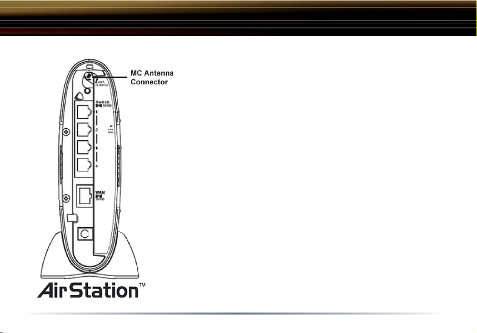
come with different connectors. The WHR2-G54 has an ‘MC
Connector’ on it. Thus, the antenna must also have an MC
connector.
To install the antenna, slide the antenna connector door on
the back of the WHR2-G54 to the right. This will expose the
MC Connector. Attaching the antenna is simple, just insert
the antenna’s MC Connector into the WHR2-G54’s MC Connector and fi rmly push it in until it snaps into place. Once
snapped, the antenna’s connector will swivel with ease. It is
important not to push the antenna connector in at an angle.
To remove the antenna, pull the antenna connector out. It is
important not to pull the antenna connector out at an angle.
11
Standard Settings
3.4 Open the Setup Screen
• Connect the WBR2-G54 according to the wiring instructions in Section 2.
• The WBR2-G54 has a default LAN IP address of 192.168.11.1 and Subnet Mask of
255.255.255.0.
Fig ure 3.4
Initial
Settings
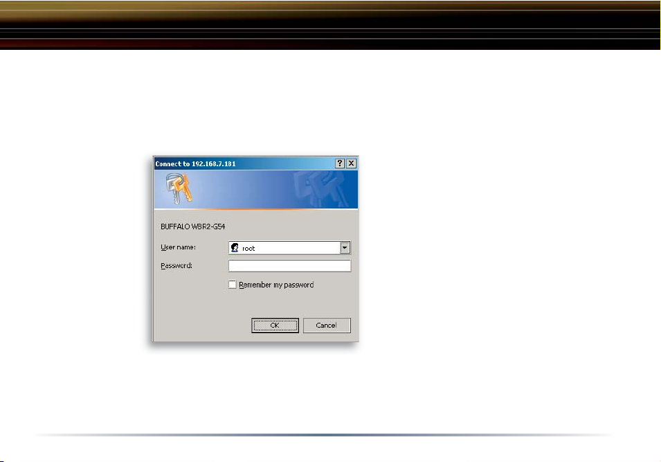
Login
Enter “root” as the User ID and leave the password fi eld blank.
■ Note: These are the factory default settings
■ Note: The computer used to confi gure
the AirStation should be set to obtain an
IP address automatically using a DHCP
server. The Quick Setup Guide enclosed
with the product contains detailed instructions on how to confi gure your computer
for initial confi guration.
On the computer used to confi gure the
AirStation, launch a Web Browser 4.5 or
later.
- Enter 192.168.11.1 into the URL fi eld.
- A window will open prompting you to
enter a User ID and Password
12
Standard Settings
Fig ure 3.5
Initial
Settings
Screen
Fig ure 3.5.1
Initial DSL
button
Screen
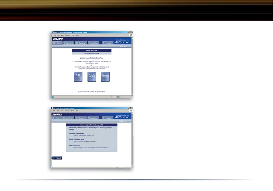
3.5 Enter ISP information
• Click the appropriate button to select the type
of broadband access. (Usrs more experienced
in networking may choose to select the Advanced button and skip to Section 4.)
• For supplementary tools, use the tabs along
the top of the screen.
3.5.1 DSL Button
Select the appropriate connection method.
Automatic IP Assignment by ISP
- The DHCP server of the ISP assigns an IP address automatically.
13
Standard Settings
Fig ure
3.5.1a
Manual DSL
IP Settings
Screen
Fig ure
3.5.1b
DSL PPPoE
Settings
Screen
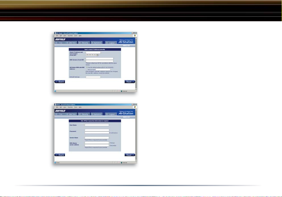
Enter IP address manually
- Enter the IP address given by the ISP.
- Use ‘Enter IP address manually’ if the ISP
requires use of a static IP address.
PPPoE Connection
- Enter the PPPoE information provided by the
ISP.
14
Standard Settings
Fig ure 3.5.2
Initial CATV
Settings
Screen
Fig ure 3.5.2a
Manual IP
Address
Settings
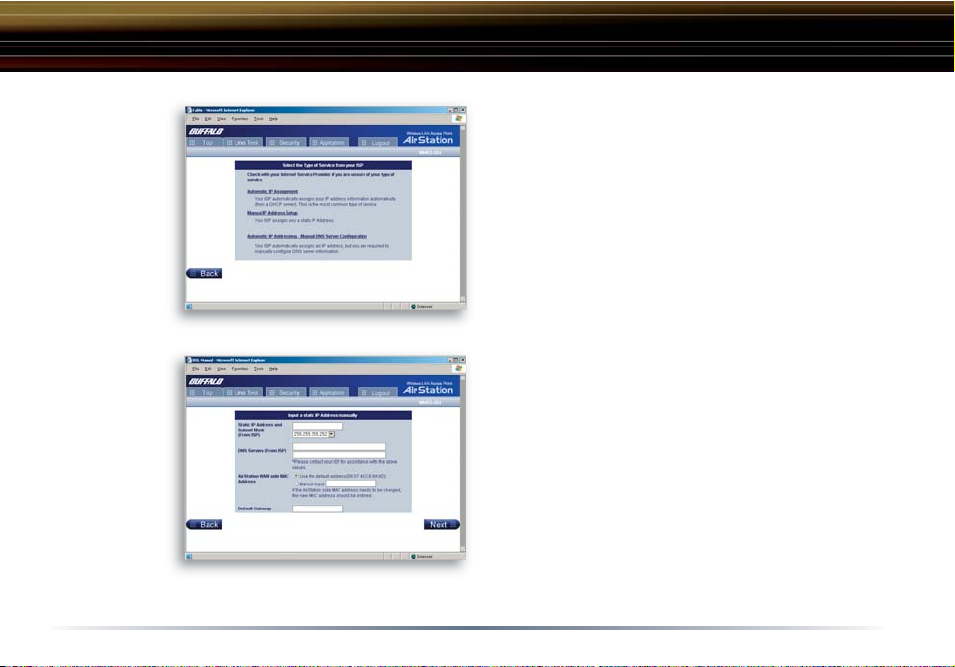
3.5.2 CATV (Cable) Button
Select the appropriate connection method.
Automatic IP Assignment by ISP
- Select ‘Automatic IP Assignment by ISP’ if
your ISP’s DHCP server assigns an IP address
automatically.
Enter IP address manually
- Select ‘Enter IP address manually’ if the ISP
requires use of a static IP address.
15
Standard Settings
Fig ure 3.5.2b
Auto IP/
Manual DNS
Settings
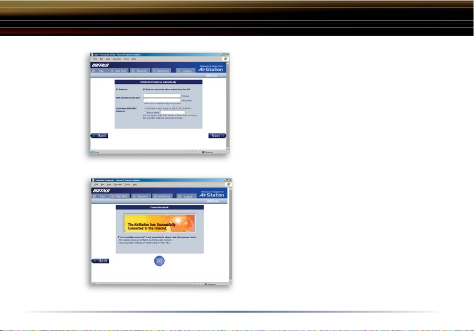
Fig ure 3.5.3
Line
Test Tab
The IP address is acquired
au to mat i cal ly but DNS server address
is entered manually
-
Select ‘IP address is acquired automatically
but DNS server address is entered manually’ if
the ISP’s DHCP server supplies an IP address
but not DNS server addresses.
3.5.3 Line Test Tab
Tests the connection to the Internet.
16
Standard Settings
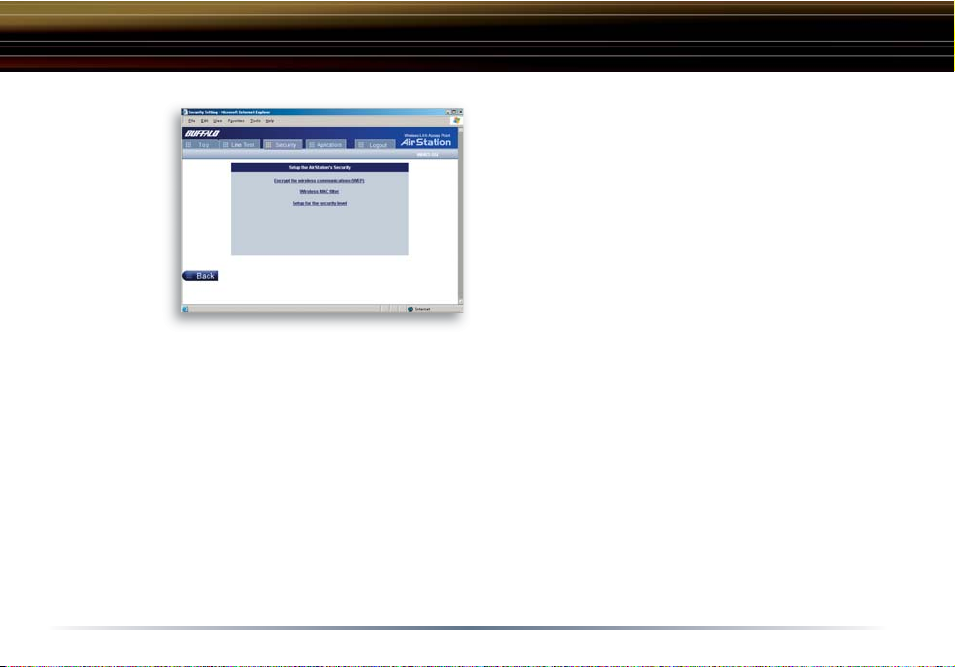
Fig ure 3.5.4
Security Tab
3.5.4 Security Tab
The Security Tab offers three Simple Security
Settings. Follow the in struc tions in each screen
to enter WEP keys, MAC Address Filtering and
the degree of fi rewall security for the AirStation.
17
Standard Settings
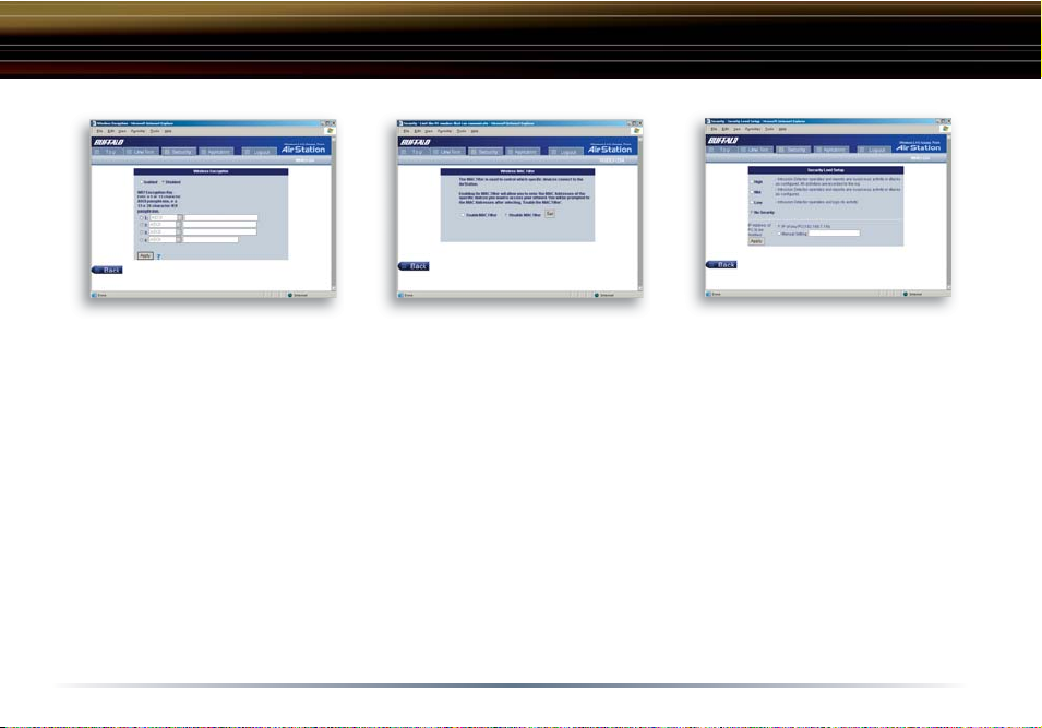
Fig ure 3.5.4a
Simple WEP Setup.
- Select the desired encryption and
enter an appropriate WEP key to
encrypt your network. See the
section on Wireless LAN Security
starting on ‘Page 22’ for more
information on encryption.
Fig ure 3.5.4b
Simple MAC Address Filter.
- Select ‘Limit’ to use MAC fi lter-
ing. See ‘Page 30 for more information on MAC Address Filtering.
18
Fig ure 3.5.4c
Simple Security Setup.
- See ‘Page 49’ for more information
on Intrusion Detector.
Standard Settings
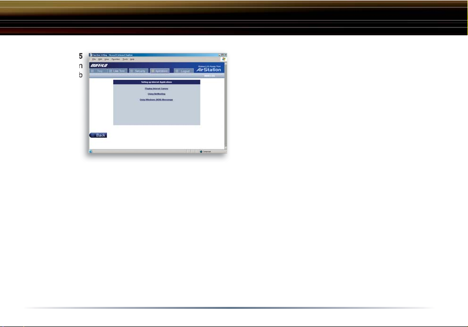
Fig ure 3.5.5
Ap pli ca tion
Ta b
Although your AirStation will function fi ne using only the settings from Section 3, you may wish to
explore more advanced options. Chapter 4 explains each function in the Advanced settings area.
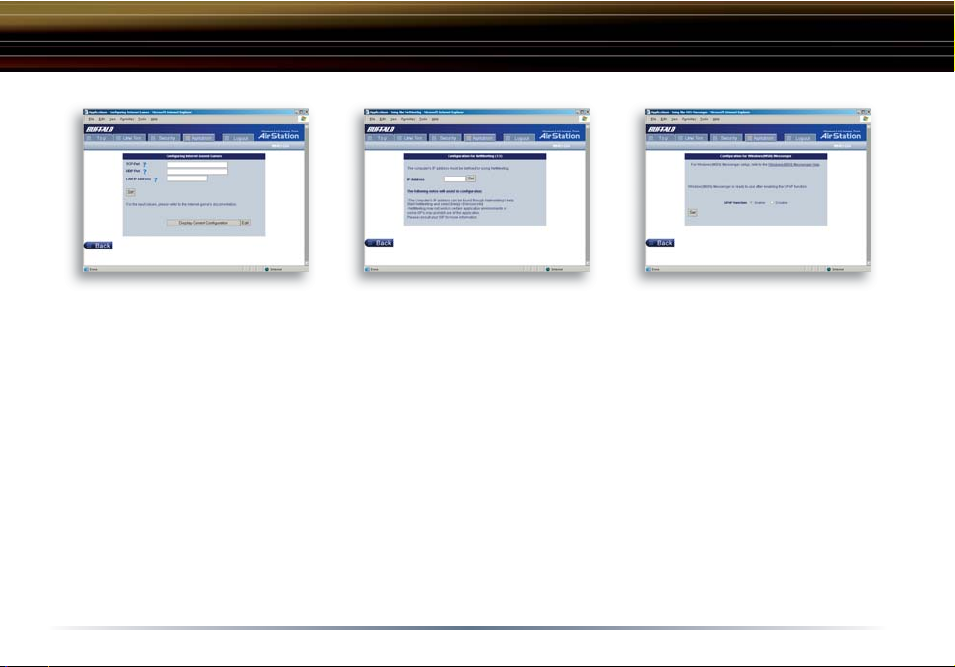
3.5.5 Application Tab
The Application Tab offers setup for special
applications such as games, MS NetMeeting
and MSN Messenger. Follow the instructions
in each screen.
19
Standard Settings
Fig ure 3.5.5a
Web Gaming Setup
-Enter the ports(refer to Game
documentation) the game runs
on, and enter the Local IP Address of the PC that plays the
game.
Fig ure 3.5.4b
NetMeeting Setup
-Enter the IP Address of the PC
that will use Netmeeting.
20
Fig ure 3.5.4c
MSN Messenger Setup
-Refer to the on-screen help for
information about Messenger.
AOSS
AOSS (AirStation One-Touch Secure System) is a simple, one-touch setup for connecting wireless
clients to an access point while setting up the most secure possible connection. Users no longer
need to worry about choosing the proper security protocols, IP addresses, or ESS-ID's. The
intelligence of AOSS determines the most optimal connection and confi gures itself in seconds.
■ NOTE: AOSS automatically creates a secure connection between your AOSS Access Point and
client. You must have a Buffalo AOSS enabled wireless client device to use the AOSS features of
your AOSS Access Point/Router.
◗ Confi gure your WBR2-G54's internet con-
nection by referring to the instructions in
the WBR2-G54's Quick Setup Guide.
◗ Once the WBR2-G54 has been confi g-
ured, follow the directions to install your
wireless client device and its drivers if
necessary. Certain wireless client adapters require client software to confi gure
them. If your device has a Client Manager, then install it as well.
■ NOTE: If the wireless client adapter is
installed on a PC, then the AOSS client
manager will need to be installed as well. If your wireless client adapter is a standalone device that
does not require a PC, then just power up the device.
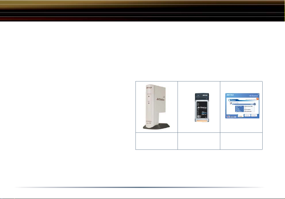
Standalone Devices: Ethernet Converters and Access Point Bridges
Client Manager Devices: CardBus, USB, and PCI Adapters.
Standalone
AOSS Device
21
Client Manager
Device
Client Manager
Software
AOSS
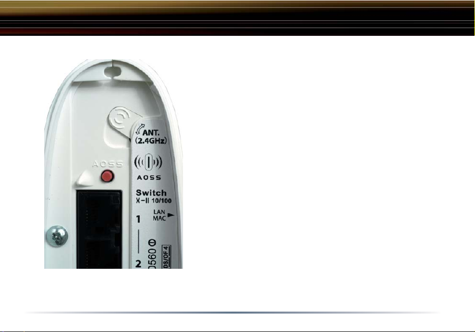
◗ Now that the WBR2-G54 and wireless client adapter are
installed, you can use AOSS to confi gure them.
◗ To begin the confi guration, press the AOSS button on
the back of the WBR2-G54 for 3-5 seconds. The AOSS
light will begin to fl ash when the AOSS mode has been
enabled. You can stop pressing the button at this point.
■ NOTE: AOSS mode will stay active for a period of
two minutes. This is the time-slot required to initiate the
wireless client adapter. The AOSS LED will stop fl ashing
when AOSS mode has stopped or timed out.
◗ Refer to your wireless client adapter's AOSS
supplement to initiate the wireless client adapter's AOSS
mode.
◗ It typically takes 10-15 seconds for the AOSS light to
stop fl ashing after the AOSS button has been pressed
on the wireless client adapter. Once confi guration is
complete, the AOSS light will remain steady. Please
refer to your wireless client adapter's supplement for the
remainder of the setup.
22

Additional AOSS Information:
◗ Only one AOSS wireless client adapter can be confi gured to the AOSS router at a time. Thus,
the button will need to be repressed for each additional AOSS wireless client adapter that will be
connected.
◗ It is not necessary to AOSS client devices that have already been confi gured via AOSS, unless
signifi cant changes have been made to the wireless network.
◗ Do not attempt to confi gure two separate AOSS networks at the same time, as it may cause
undesired confi gurations.
◗ If an undesired client has connected via AOSS, it can be disconnected from within the WBR2-
G54's advanced confi guration menus.
23
Click the Top tab and click the Advanced button.
Advanced Settings
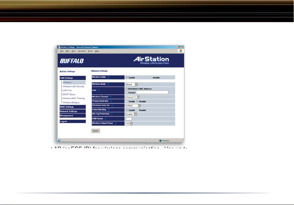
Fig ure 4.1.1
Wireless
Settings
4.1 LAN Settings
Set up LAN connections.
4.1.1 Wireless
Wireless Function - Enable or
disable wireless LAN computer
communication.
ESS-ID (SSID) - Allows administrator to alter the ESS-ID
of the AirStation. To communicate with a specifi c AP
only, the AP’s ESS-ID must be
entered in the client computer.
The client computer looks for
the specifi c AP (or ESS-ID) for wireless communication. Use up to 32 al pha nu mer ic characters for
the ESS-ID (case sensitive). By default the ESS-ID is the LAN Mac address of the AirStation.
■ Note: Roaming - When multiple AirStations have an identical ESS-ID, WEP key (if WEP is used),
(and channel in WDS mode) , client computers may Roam between the AirStations.
Wireless Channel - Select the channel used for wireless communication. There are 11 overlapping channels. Channels 1, 6 and 11 are non-overlapping.
24

Advanced Settings
If there are multiple APs in close proximity using the same channel, there may be interference. In
this case, change to a non-overlapping channel.
Privacy Separator - Enable or disable communication between wireless clients. If you choose to
use this feature, every wireless client that is associated to the AirStation will not be able to communicate with any other wireless clients.
■ Note: If this function is used, wired clients can still communicate with wireless clients.
BSS (Basic Service Set) Basic Rate Set - The transmission data rates offered by the AirStation.
It is recommended to use the ‘Default’ selection to accomidate 802.11 and 802.11b rate sets. It is
NOT recommended to use the ‘All’ selection, as some devices may not understand all of the rate
sets offered by the AirStation.
Frame Bursting - This function increases 802.11b communication throughput by transferring packets more effi ciently. The following conditions affect this function:
• The wireless LAN client adapter must support Frame Bursting (and it must be enabled). If
the wireless LAN client adapter does not support Frame Bursting, or Frame Bursting is not
enabled, then it will operate at non-Frame Bursting speeds.
It is recommended to leave Frame Bursting enabled as it can only help throughput, not hurt it.
DTIM Period - An access point transmits beacon signals to nearby clients at a preset interval. This
parameter sets the beacon transmission interval time (1-255 seconds). Se lec tion of a larger number may conserve energy for the client computer (when client power management is enabled), but
may delay wireless communication. The default value of 1 is recommended.
25
Advanced Settings
Wireless output power - Confi gure output power of the AirStation. Decrease wireless output
power to shrink the wireless communication range. The default setting of 100% is recommended
unless decreased range is desired
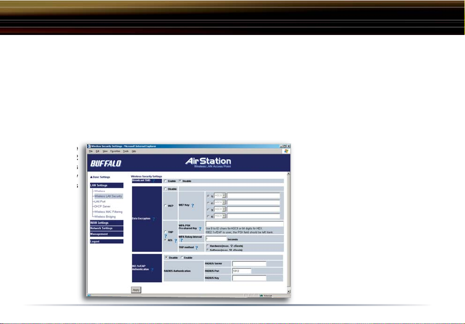
4.1.2 Wireless LAN Security
Broadcast SSID - Enable or Disable the SSID (ESS-ID) from being broadcasted. If denied, the
AirStation will not be found unless the specifi c AirStation’s SSID is entered in the client computer
manually.
Fig ure
4.1.2
Wireless
Security
Settings
Data Encryption - Disable
to have no encryption of the
wireless data. This will make
accessing the AirStation and
the network very easy. It is
important to note, that without
encryption it is easy for strangers to connect to your network,
especially if the AirStation is
broadcasting its SSID.
Select the type of data encryption:
26

Advanced Settings
• Disabled - Disable data encryption.
- WEP - Uses WEP encryption. Encryption key should be entered.
- TKIP - Uses TKIP (Temporal Key Integrity Protocol) for data encryption.
The encryption key is renewed every “Re-key interval” when “TKIP” is selected.
WEP - When the WEP (Wired Equivalent Protection) encryption standard is implemented into a
wireless network, a WEP key is used between the client and access point to successfully encrypt,
transmit and decrypt data. For this reason, the same WEP key must be used for communication
between the client and the AirStation.
An access point and client may both carry multiple WEP keys. It is necessary for not only the WEP
keys to match, but also the WEP key’s order. If a wireless client cannot support multiple WEP keys,
the AirStations must be confi gured to transmit key number 1 for a connection to take place.
Examples of WEP key:
64-bit ASCII: 5 digits of alphanumeric characters, “ab34Y”
128-bit ASCII: 13 digits of alphanumeric characters, “123456abcdef7”
■ Note: ASCII WEP keys are case sensitive.
64-bit HEX: 10 digits, using characters 0-9 and a-f, “00234ABCDE”
128-bit HEX: 26 digits, using characters 0-9 and a-f, “20123456789abcdeabcdeabcde”
TKIP - TKIP (Temporal Key Integrity Protocol) is a WEP expanded encryption technique. TKIP has
27
 Loading...