

Page 1
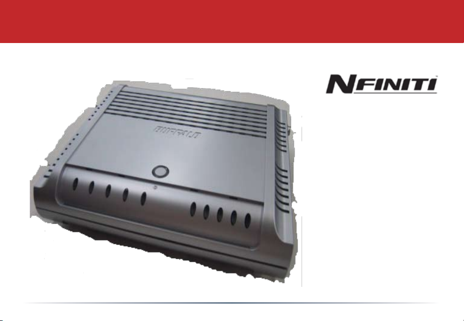
User Manual - AirStation Draft-N WZR-AG300NH
Nniti Wireless Router & AP
www.buffalotech.com
v. 1.00
Page 2

Table of Contents
Introduction . . . . . . . . . . . . . . . . . . . . . . . . . . . 5
Basic Setup . . . . . . . . . . . . . . . . . . . . . . . . . . . . . . 6
AOSS . . . . . . . . . . . . . . . . . . . . . . . . . . . . . . . . . . . . . . . . 12
Router Access Point Mode . . . . . . . . . . . . . . . . . . . . . . . . . . . 14
AirStation Conguration Tool . . . . . . . . . . . . . . . . . . . . . . . . 17
Home . . . . . . . . . . . . . . . . . . . . . . . . . . . 17
Port Mapping . . . . . . . . . . . . . . . . . . . . . . . . . . . 18
Firewall . . . . . . . . . . . . . . . . . . . . . . . . . . . 19
Windows (MSN) Messenger. . . . . . . . . . . . . . . . . . 20
Encryption . . . . . . . . . . . . . . . . . . . . . . . . . . . 21
Wireless Channel . . . . . . . . . . . . . . . . . . . . . . . . . . . 22
Firmware Update . . . . . . . . . . . . . . . . . . . . . . . . 23
Internet Connection Reset . . . . . . . . . . . . . . . . . . . . . 24
Advanced Settings . . . . . . . . . . . . . . . . . . . . . . . . . . . 25
WAN Conguration . . . . . . . . . . . . . . . . . . . . . . . . 26
WAN port . . . . . . . . . . . . . . . . . . . . . . . . . . . . . 26
PPPoE. . . . . . . . . . . . . . . . . . . . . . . . . . . . .27
LAN Conguration . . . . . . . . . . . . . . . . . . . . . . . 28
LAN Port . . . . . . . . . . . . . . . . . . . . . . . . 28
2
Page 3

Table of Contents
DHCP Server . . . . . . . . . . . . . . . . . . . . . 29
Manual Assignment of IP Address . . . 30
Network Conguration. . . . . . . . . . . . . . . . . . . . . 31
Route information . . . . . . . . . . . . . . . . . . . . 31
Address Translation . . . . . . . . . . . . . . . . . . . . . . . . . . 33
IP Filter . . . . . . . . . . . . . . . . . . . . . . 35
Intrusion Detector . . . . . . . . . . . . . . . . . 38
UPnP . . . . . . . . . . . . . . . . . . . . . . . . . . . 39
Wireless Conguration . . . . . . . . . . . . . . . . . . . . . . . . 40
AOSS. . . . . . . . . . . . . . . . . . . . . . . . . 40
802.11a . . . . . . . . . . . . . . . . . . . . . . 41
802.11g . . . . . . . . . . . . . . . . . . . . . . 44
MAC access limit . . . . . . . . . . . . . . . . . . . . . . . . 47
Edit Registration List. . . . . . . . . . . . . . . . . . . . . . . . 48
Admin Conguration . . . . . . . . . . . . . . . . . . . . . . . . . . . . . . . . . 49
Password . . . . . . . . . . . . . . . . . . . . . . . . . . . . . . . . 49
Date/NTP . . . . . . . . . . . . . . . . . . . . . . . . . . . . . . 50
3
Page 4

Table of Contents
Syslog Transfer . . . . . . . . . . . . . . . . . . . . . . . . . . . 51
Save/Load Conguration . . . . . . . . . . . . 52
Initialize/Reboot . . . . . . . . . . . . . . . . . . . . . . . . . . . 53
Firmware Update. . . . . . . . . . . . . . . . . . . . . . 54
Diagnostic. . . . . . . . . . . . . . . . . . . . . . . . . . . . . . . . . . . . 55
System Information. . . . . . . . . . . . . . . . . . . . . . 55
Log Info. . . . . . . . . . . . . . . . . . . . . . 56
Packets Info. . . . . . . . . . . . . . . . . . . . . . 57
Client Monitor. . . . . . . . . . . . . . . . . . . . . . 58
Ping Test. . . . . . . . . . . . . . . . . . . . . . 59
Connecting to an Existing Network. . . . . . . . . . . . . . . . . . . . . . 60
Specications . . . . . . . . . . . . . . . . . . . . . . . . . 61
Troubleshooting . . . . . . . . . . . . . . . . . . . . . . . . . . . . . . . 64
Glossary . . . . . . . . . . . . . . . . . . . . . . . . . . . . . . . . . . .67
FCC/CE/R&TTE . . . . . . . . . . . . . . . . . . . . . . . . 74
Warranty Information. . . . . . . . . . . . . . . . . . . . . 78
Contact Information . . . . . . . . . . . . . . . . . . . . . 79
4
Page 5

Introduction
Work and play - further and faster! Eliminate dead spots and enjoy faster connections with
vastly extended range from Buffalo Technology’s amazing wireless solution, the AirStation
Draft-N Nniti Wireless Router & AP.
System Requirements
• A high-speed (Broadband) Internet connection or existing local area connection.
• A computer with a network connection (wired or wireless) and a good web browser. The
screenshots in this manual were taken with Firefox, but Netscape and Internet Explorer
are also supported in versions 4.5 or later, and Safari 1.0 and later are supported with
Macintosh OS X 10.2 and later.
AirStation WZR-AG300NH Package Contents
The AirStation WZR-AG300NH package contains the following items:
• WZR-AG300NH AirStation
• AC adapter and power cable
• CAT5 LAN cable
• Utility CD with Manual
• Quick Setup Guides
• Warranty Statement
5
Page 6

Basic Setup
Begin by nding a good place to set up your router/access point. Some things to
consider:
• You’ll need to be able to plug your internet connection into it, so it should go within
reach of the LAN cable from your DSL or Cable modem. You’ll also want a power outlet
nearby.
• Keep the access point as central in your work area as possible. Signal strength and
speed fall off with distance.
• Higher is often better. For instance, set it up on the top shelf of a bookcase rather than
the bottom one, if possible.
6
Page 7
Getting Ready
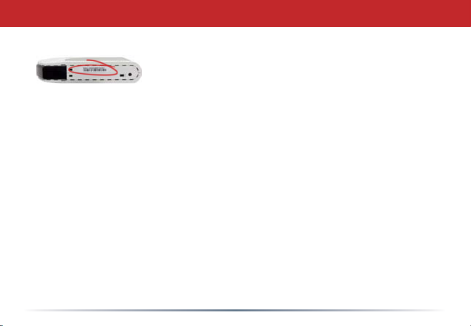
Make note of the AirStation’s wired MAC address. The LAN
or Wired MAC address is the default SSID (wireless network
name) of the AirStation. You can find it on the bottom of the
AirStation.
You may also wish to contact your ISP to ask if other information, such as global IP
address, subnet mask address, default gateway address, DNS server address, or PPPoE
parameters, is necessary to access your internet connection. Write down any necessary
information that your ISP requires for connection.
Buffalo recommends using a wired network connection, where your computer is
physically connected to the AirStation with a CAT5 straight cable plugged into one of the
four LAN ports, to initially set up your router. This type of setup will eliminate possible
setup problems with the wireless adapter on the computer being used to congure the
AirStation.
The computer used to congure the AirStation should be set to obtain an IP address
automatically using a DHCP server. The WZR-AG300NH has a default LAN IP address of
192.168.11.1 and Subnet Mask of 255.255.255.0.
7
Page 8
Connecting your AirStation
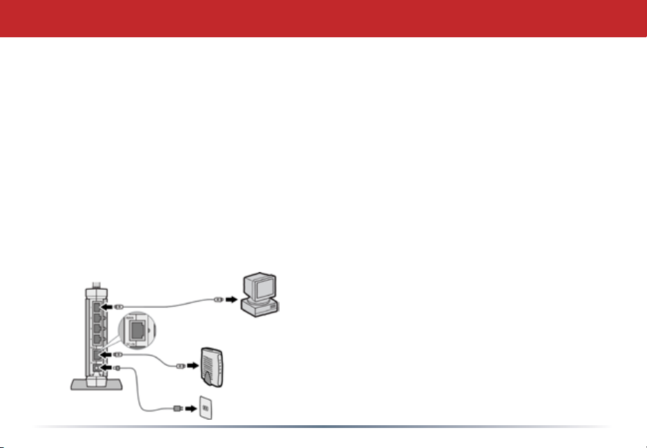
1. Power down the Cable or DSL modem and the computer which will be used to
congure the AirStation router.
2. Plug the Cable or DSL’s LAN Ethernet cable into the AirStation’s WAN port. Initially,
you may need to unplug this cable from your computer, hub or other router.
3. Plug the provided Ethernet cable into a LAN port on the AirStation and plug the other
end into your computer’s Ethernet adapter (NIC). If you plan to initially congure the
AirStation wirelessly (not recommended), you may skip this step.
4. Power on your cable or DSL modem and wait one full minute, then power on the
AirStation router and wait one full minute, and nally power on the computer which
will be used to congure the AirStation. If the red DIAG light on the AirStation is lit or
ashing after several minutes of being powered on, please consult Buffalo Technology
Technical Support.
8
Page 9
Log in to the Conguration Tool
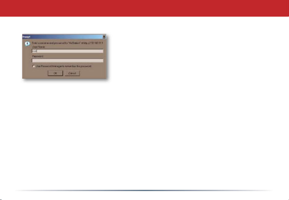
Launch a web browser on the computer that you’re
going to use to congure the AirStation.
Enter 192.168.11.1 into the URL eld. Naturally, if you
change your AirStation’s IP address, you’ll have to enter
the new address instead.
A window will open, prompting you to enter a User ID
and Password.
Enter root as the User name and leave the password
eld blank.
9
Page 10
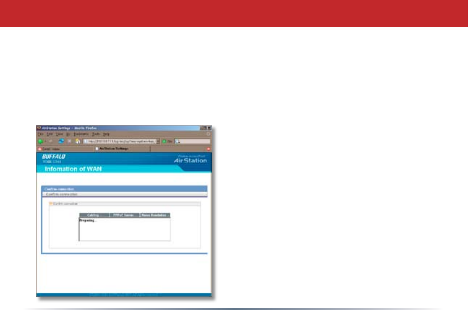
Detecting Your Broadband Connection
Your AirStation’s SmartRouter technology will determine the type of internet
connection you have automatically, and ask you for any needed information. If
your ISP assigns IPs automatically (most cable providers do), their DHCP server
will give your router an IP address. If additional login information is required
to connect to the internet, the wizard will ask for it. Enter any required login
information if asked. Contact your DSL
provider for any missing login information.
If your DSL provider requires that PPPoE
information be entered manually, see page
25.
10
Page 11
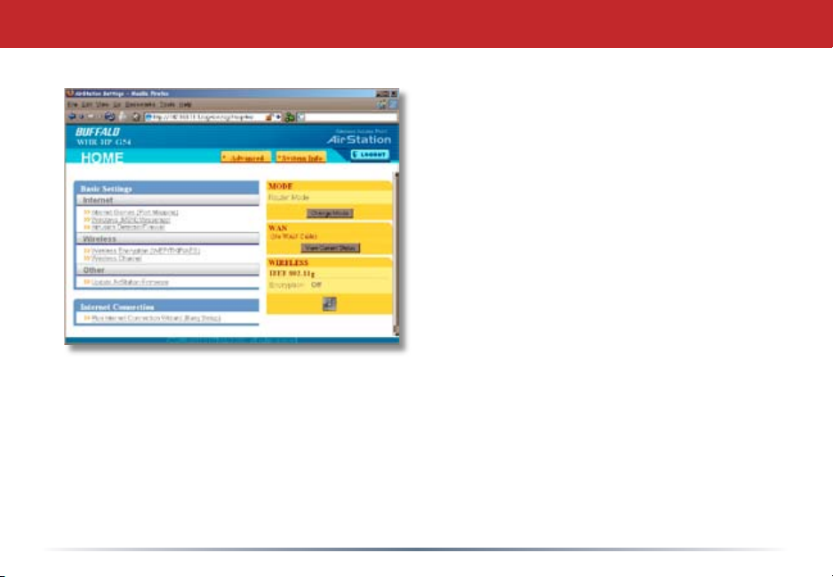
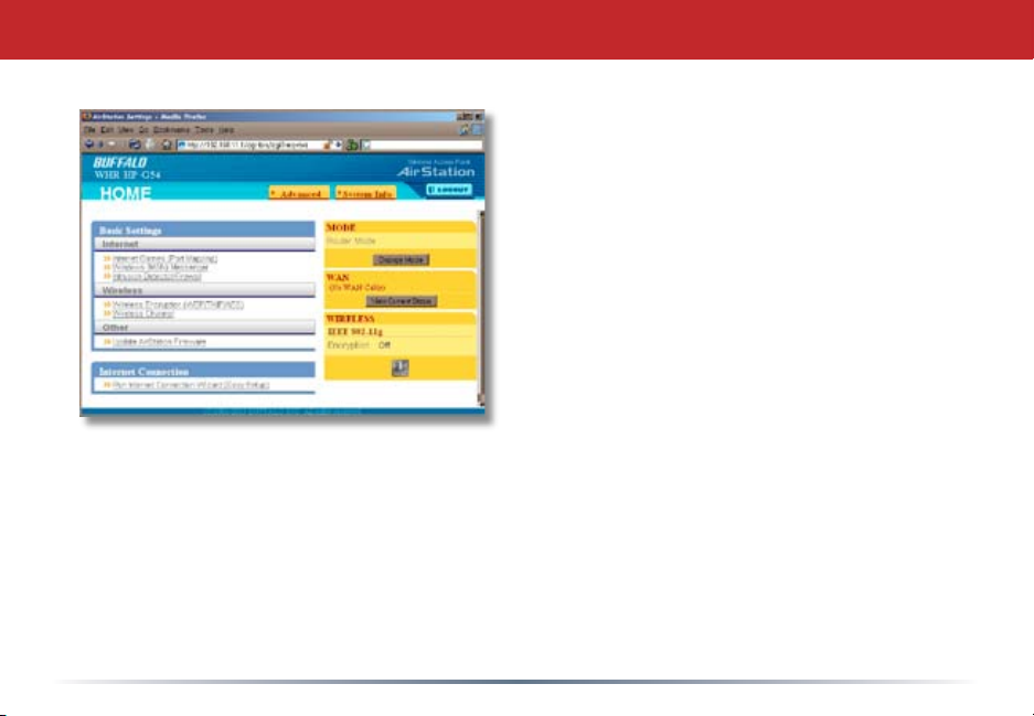
Home
This is the opening page of your
AirStation’s conguration tool. You
can always get to it from within the
conguration screens by clicking on
Home. From here, you can congure
port mapping for your internet games,
turn on UPnP for Windows (MSN)
Messenger, congure your Firewall,
setup Encryption, choose your Wireless
channel, update your AirStation’s
rmware, and reset your Internet
connection’s conguration. As you
explore the conguration tool, you can
usually get context sensitive help by clicking on the Help link at the top right of
the page.
To go to Advanced Settings (page 25), click on the Advanced tab. To get the
system information you need to set up a wireless client that doesn’t support
AOSS, click on the System Info tab. See page 17 for more on Home.
11
Page 12
AOSS
AOSS
AOSS (AirStation One-Touch Secure System) is a simple system for conguring
your wireless network securely. If your router and your client device are
installed and both support AOSS, then making a secure wireless connection
between them is very easy.
Push the AOSS button on the top of your router and hold it in for a few
seconds. The AOSS light will begin to ash amber. You now have two minutes
to push the AOSS button on your client device and nish the connection.
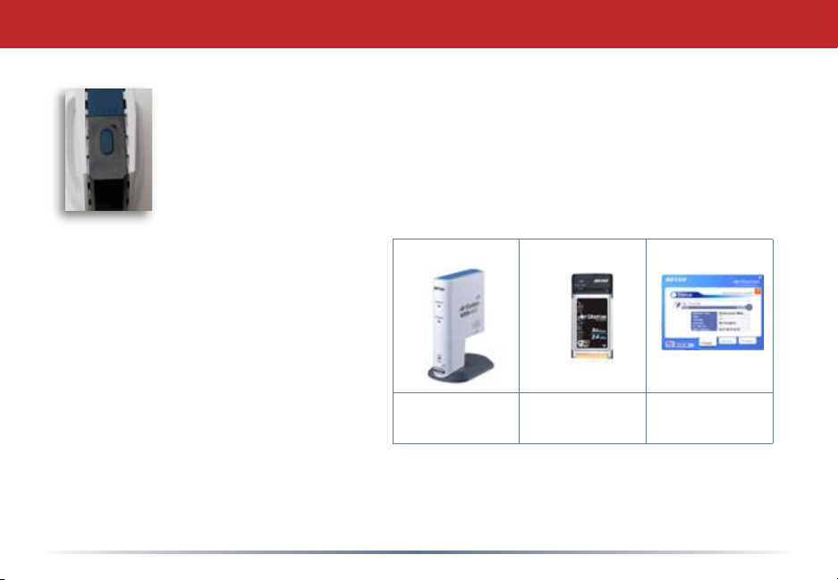
If you have a standalone client device,
it will probably have a little red button
labled “AOSS” on it. Push the button!
About 15 seconds later, you’ll have a
secure network connection.
If your client device is a PC card,
CardBus, or PCI adaptor, the AOSS
button will probably be in its Client
Manager Software. Check your client
device’s user manual for instructions
on where to push or click the AOSS
button.
After you’ve pressed both buttons, it will take about 15 seconds for the connection to
complete. When it’s nished, the AOSS light witll glow a solid amber. You now have a
secure network connection!
standalone
client device
PC card Client Manager
Software
12
Page 13

AOSS Notes
Some things to keep in mind with AOSS:
• Only one AOSS wireless client adapter can be congured with the AOSS router at a
time. The buttons will need to be re-pressed to connect each additional AOSS wireless
client adapter.
• It is not necessary to AOSS client devices that have already been congured via AOSS,
unless signicant changes have been made to the wireless network.
• Do not attempt to congure two separate AOSS networks at the same time, as it may
cause undesired congurations.
• If an undesired client has connected via AOSS, it can be disconnected from within the
WZR-AG300NH’s advanced conguration menus.
13
Page 14
Router/Access Point Mode
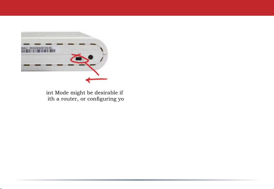
This AirStation supports quickly changing the
product from a wireless router to a conventional
access point.
Put your Airstation into Access Point Mode
by moving the switch on the bottom of your
AirStation from AUTO to BRI. This changes
the default IP address of the AirStation from
192.168.11.1 to 192.168.11.100, and DHCP,
NAT, and the WAN port are disabled.
Access Point Mode might be desirable if you’re adding wireless capability to an existing
network with a router, or conguring your AirStation as part of a bridge setup. It is not
suitable for most home congurations. If you plan to use the AirStation as an normal
wireless router, make sure that this switch is in the normal (AUTO) position!
To set up your AirStation as a bridge, ip the switch to BRI.
14
Page 15
Manual Client Conguration
If your wireless client doesn’t support
AOSS, you’ll have to congure it
manually. From the Home page, click
on the System Info tab.
15
Page 16

System Info
This page gives you all the information
you might need to congure your
non-AOSS wireless client. Probably
you’ll just need the SSID, encryption
type, and password. Consult your
wireless client’s documentation for
more information on conguring it if
necessary.
You can get here from Home by
clicking the System Info tab.
16
Page 17
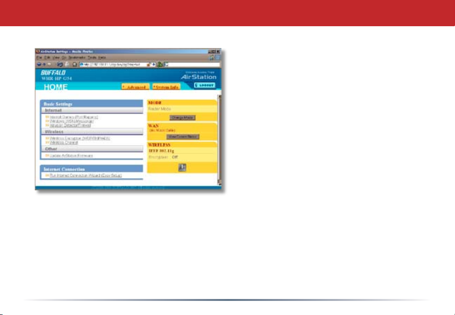
AirStation Conguration Tool (Home)
When you rst open your AirStation
Conguration Tool, it will take you to Home
(see also page 11). From Home, you can
congure port mapping for your internet
games, set UPnP for Windows (MSN)
Messenger, congure your rewall, setup
encryption, choose your wireless channel,
update your AirStation’s rmware, and reset
your Internet Connection’s conguration.
Clicking the Advanced tab gives you access
to all of the AirStation’s conguration tools.
You can get back to Home from anywhere
in the management tool by clicking on the
Home button at the top left of the screen.
Let’s begin exploring advanced settings by
clicking on Internet Games (Port Mapping).
17
Page 18
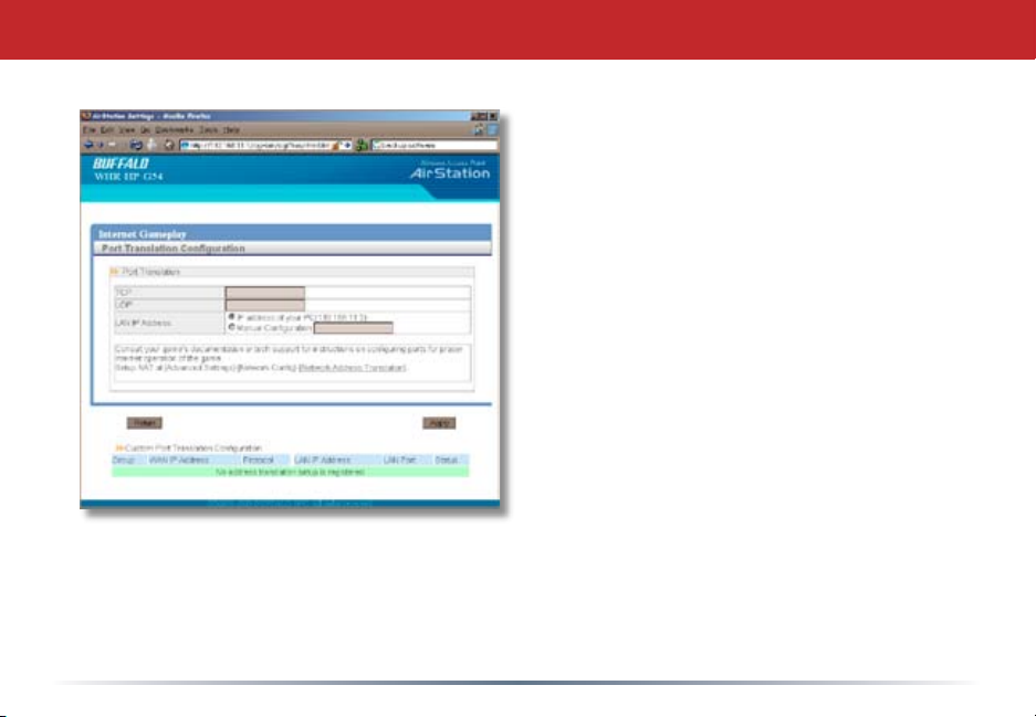
Internet Games (Port Mapping)
Select any ports that need to be
opened for your internet games to
function correctly. Consult your
game’s documentation for more
information on what ports need to be
congured.
18
Page 19
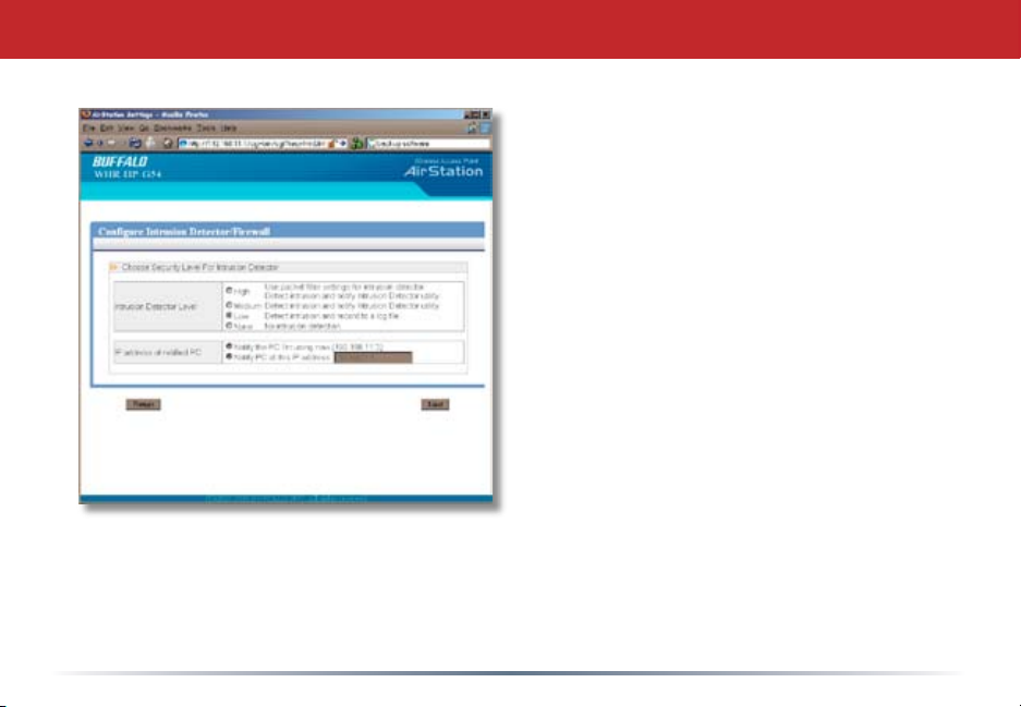
Firewall/Intrusion Detector
From this page, choose the level of rewall
security you desire. You may also choose
to have alerts sent to a different PC, if you
like. Click Next when done to restart the
router.
Get to this page from Home by clicking on
Firewall/Intrusion Detector.
19
Page 20
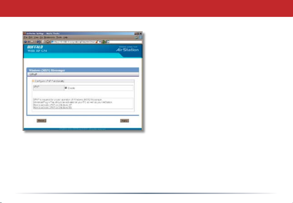
Windows (MSN) Messinger/UPnP
Windows (MSN) Messinger requires
UPnP for proper operation. You may
Enable UPnP here. UPnP may need to be
congured on your PC as well.
If you need to congure UPnP on your PC,
the links at the bottom of the page have
instructions for doing so on Windows ME
and XP computers.
Get to this page from Home by clicking on
Windows (MSN) Messinger.
20
Page 21
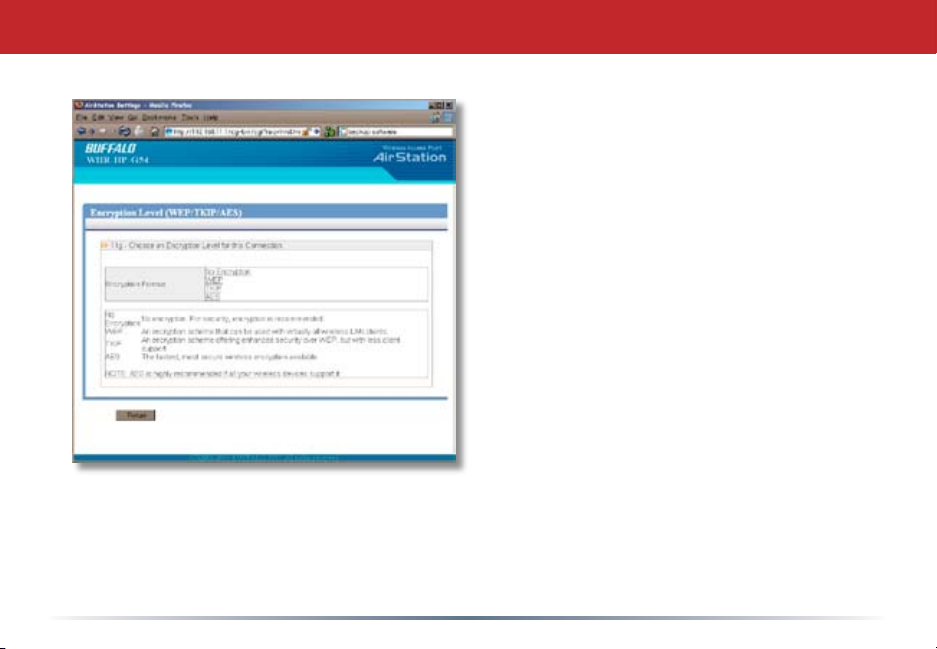
Wireless Encryption
This page is available from Home by selecting
Wireless Encryption. Here, you can manually
select the type of wireless encryption you’d
like to use. Your AirStation supports three
different encryption schemes; choose the best
one that all your clients support.
Virtually all wireless clients support WEP. It’s
a lot better than nothing.
TKIP is much more secure than WEP, but
slower.
AES is even more secure than TKIP, and the
fastest of all. Highly recommended if all of
your wireless clients support it.
21
Page 22
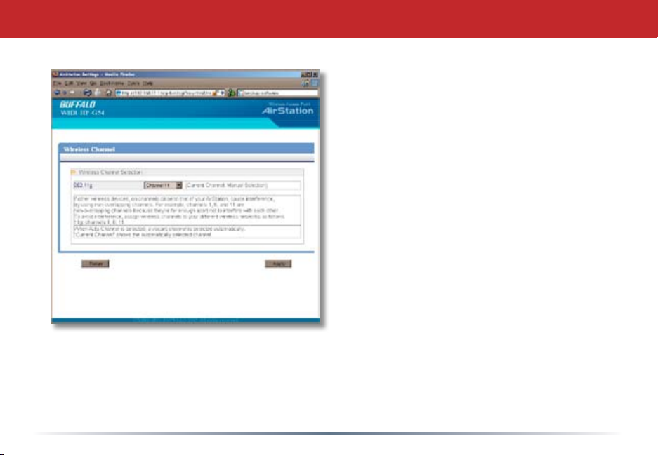
Wireless Channel
This page is available from Home by
selecting Wireless channel. With Auto
Channel selected, your AirStation will
choose the best channel available.
Current channel will show the channel
that your AirStation is currently using.
You may also select any channel from
1-11 manually. This Draft-N router
expands to use more channels then
the channel selected. This happens
automatically. This channel selection
is to choose the primary channel.
Buffalo Technology recommends
leaving this settings set to Auto
Channel unless you know a specic
channel you want to place the
AirStation on.
22
Page 23
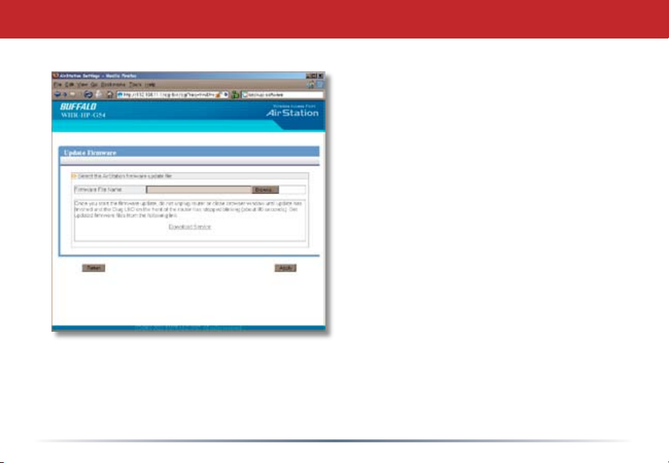
Firmware Update
This page is available from Home
by selecting Firmware update. Use
Browse to select your rmware
update le, and then click on Apply.
Firmware update may take several
minutes to complete. Don’t power
down your AirStation until the diag
LED has gone out.
23
Page 24
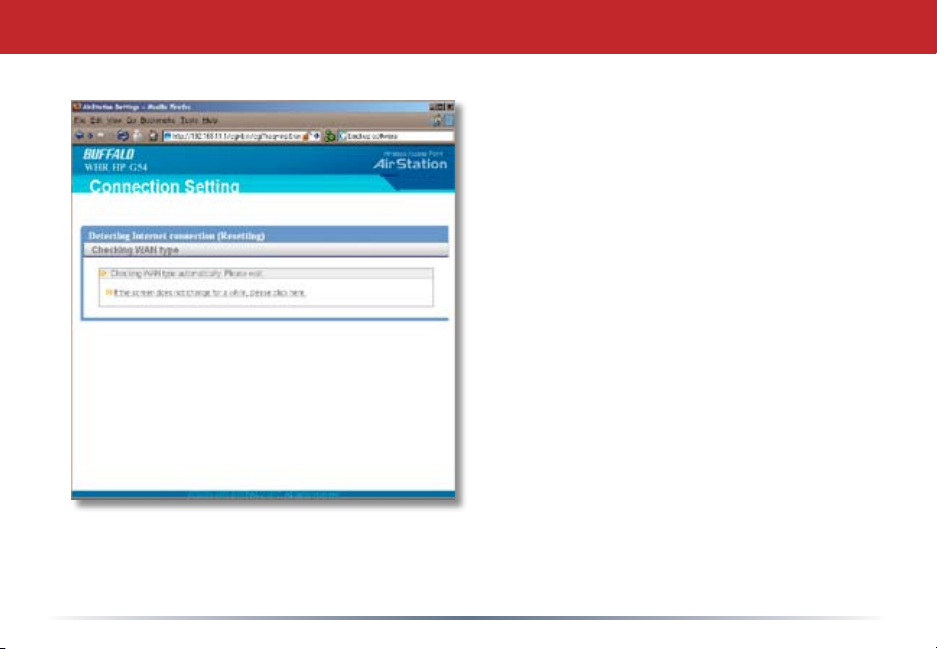
Internet Connection (Multisession Reset)
From Home, selecting the Internet
Connection Wizard (Multisession Reset)
tab will begin the Internet Connection
Wizard.
The Internet Connection Wizard will
only function correctly in simple
networks, where your cable or DSL
modem is plugged directly into your
AirStation’s WAN port. If you have
a complicated existing network that
you’re adding the AirStation to, see
page 58.
24
Page 25
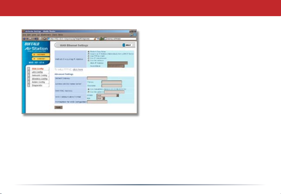
Advanced Settings
Advanced Settings lets you congure
every element of your AirStation. Get
to Advanced Settings from Home
by clicking the Advanced Tab. You
may return to Home by clicking on
the yellow > Home link in the top left
corner.
Click Help in the top right corner for
more information about any of the
pages in Advanced Settings.
To begin, click on WAN Cong. The
rst page in WAN Cong, WAN Port,
will open.
25
Page 26
WAN Cong (WAN Port)
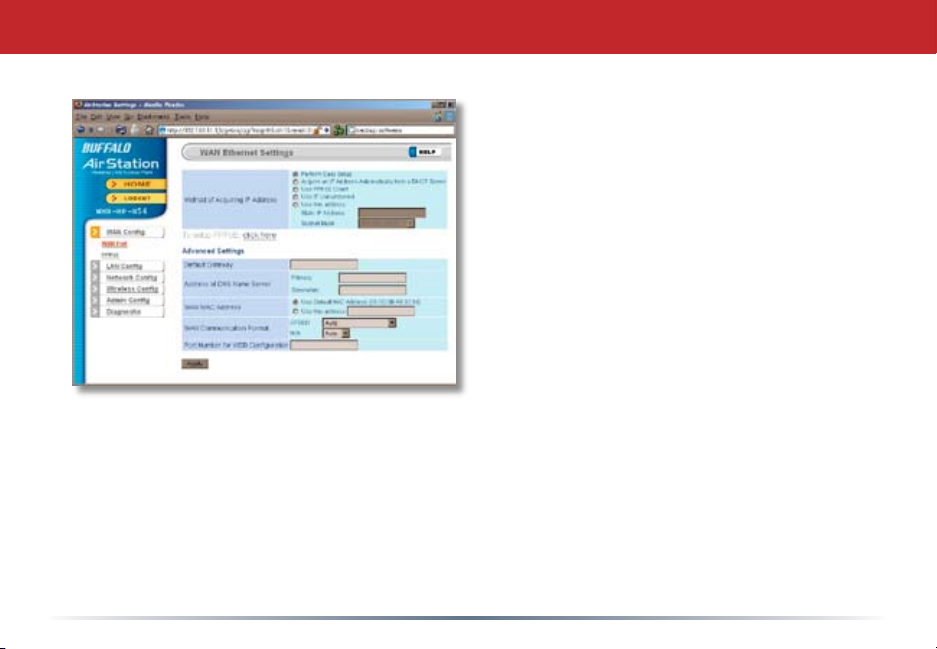
Here, you may choose how the AirStation
acquires an IP address. Normally, the
internet connection wizard will set this for
you if you have a cablemodem or DSL. If
you’re not sure what to choose, perform
Easy Setup.
To setup PPPoE manually, click on click
here and turn to page 27.
Also on this page, under Advanced Setup,
you may manually set the Default Gateway,
DNS server, WAN MAC address, WAN
format, and WEB port number.
Click Apply when nished.
26
Page 27
PPPoE
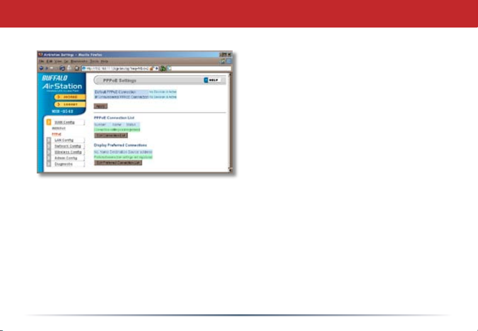
Many DSL connections require a PPPoE
Connection in order to log in to an internet
connection. Normally, the Easy Detection
Wizard will help you congure that, but
you may manually congure one here.
Consult your ISP for more information
on correctly conguring your PPPoE
connection.
To add a new PPPoE connection, click Edit
Connection List. To choose your preferred
connection, click on Edit Preferred
Connection List.
27
Page 28
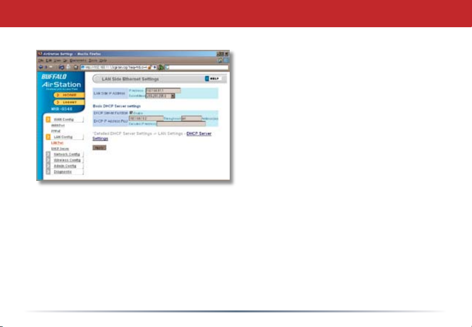
LAN Cong (LAN Port)
Default for the LAN side IP address is
192.168.11.1. To add the AirStation to an
existing LAN, specify a unique IPaddress, not
used elsewhere in the network.
The default Subnet Mask is 255.255.255.0.
To connect AirStation to an existing LAN,
specify the Subnet Mask that the LAN uses.
If there’s more than one DHCP server on
a network, disable all but one of them.
To have DHCP assign addresses from a
specic range, enter a begining address by
Assigned IP Address and give the number
of addresses to assign in the Addresses box. To exclude specic addresses from being
assigned by DHCP, specify them in the Excluded IP Address box. Multiple IP addresses
may be specied by seperating them with a comma, e.g. 192.168.11.7,192.168.11.9. You
can also specify an IP address range by start and end address connected by a dash, e.g.
192.168.11.15-192.168.11.21. The ‘,’ and ‘-’ can be used at the same time, e.g. 192.1
68.11.7,192.168.11.9,192.168.11.15-192.168.11.21, up to a total string length of 128
characters.
Click the Help link in the top right corner for more information.
28
Page 29
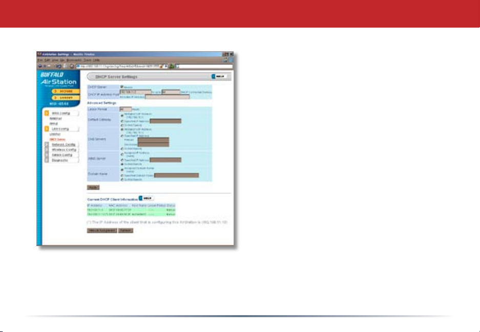
Advanced DHCP Settings
This page offers the same DHCP settings as
the previous one, and in addition, offers you
the chance to change the Lease Period, De-
fault Gateway, DNS servers, WINS server, and
Domain Name. Click Apply when you have
the settings the way you want them.
To manually assign an IP address, click
Manual Assignment.
29
Page 30
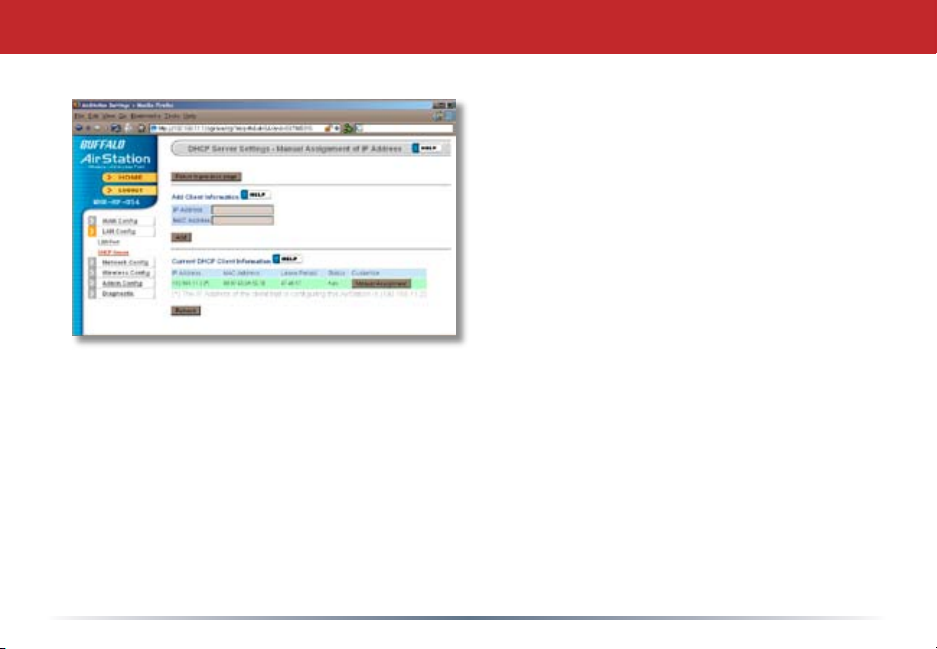
DHCP Server (Manual Assignment of IP Address)
To manually link a LAN address to a MAC
address, enter them under Add Client Infor-
mation and click Add.
Current DHCP Client Information shows
all LAN addresses currently assigned by
AirStation’s DHCP. You may congure a
specic client to always recieve the same
IP address by clicking Manual Assignment
to the right of its MAC Address. Clicking
Delete returns a manually assigned client
to normal DHCP operation. Edit allows
you to manually adjust a linked IP Address
and Mac Address in the Client Information
window above.
30
Page 31
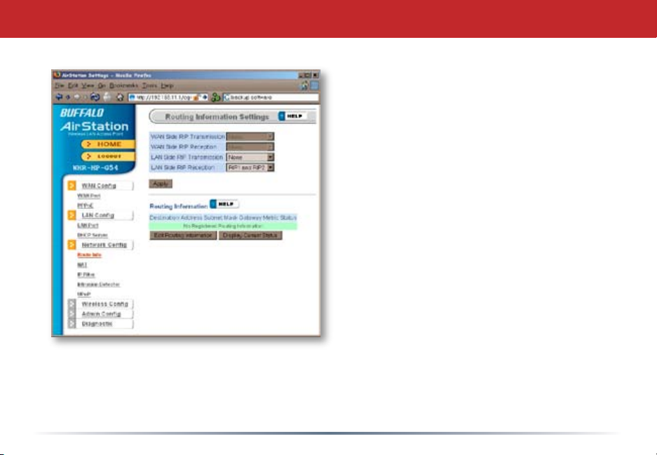
Network Cong (Route Info)
By default, the AirStation receives RIP
(Route Information Protocol) information
only from your local network, and
doesn’t broadcast RIP at all. For large,
complicated network congurations,
you may wish to modify this behavior.
Click Apply when you have your desired
conguration.
Lower on the page, routing information
is displayed. Click Edit Routing
Information to add a new route
manually.
31
Page 32
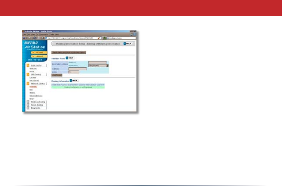
Network Conguration (Edit Routing Information)
To congure a route manually, enter its
Destination Address and Gateway. Enter
a maximum number of hops allowable in
Metric and click Add.
32
Page 33
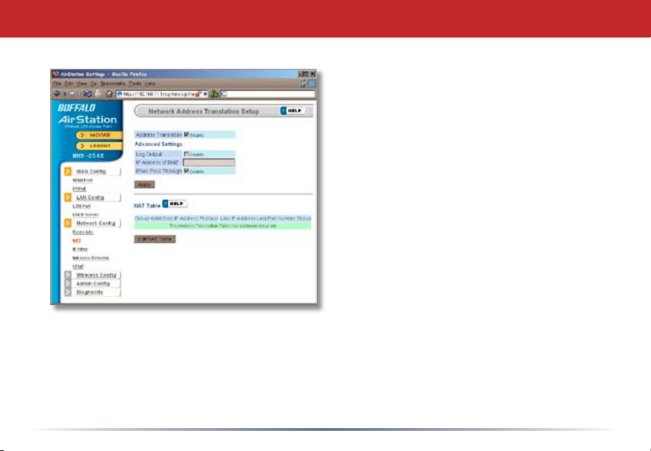
NAT
You may disable Network Address
Translation and IPsec passthrough by
unchecking the appropriate Enable boxes.
If you have a DMZ, enter its IP address
in the IP Address of DMZ box. Incoming
packets containing no recognizable
destination port information will be
redirected to the DMZ’s IP address.
Click Apply when done.
To set a NAT table entry manually, click
Edit NAT Table.
33
Page 34
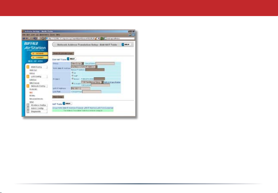
NAT (Manual Entry)
From this page you may manually add
entries into the Address Translation
Table. Click Add New Group when each is
complete.
34
Page 35
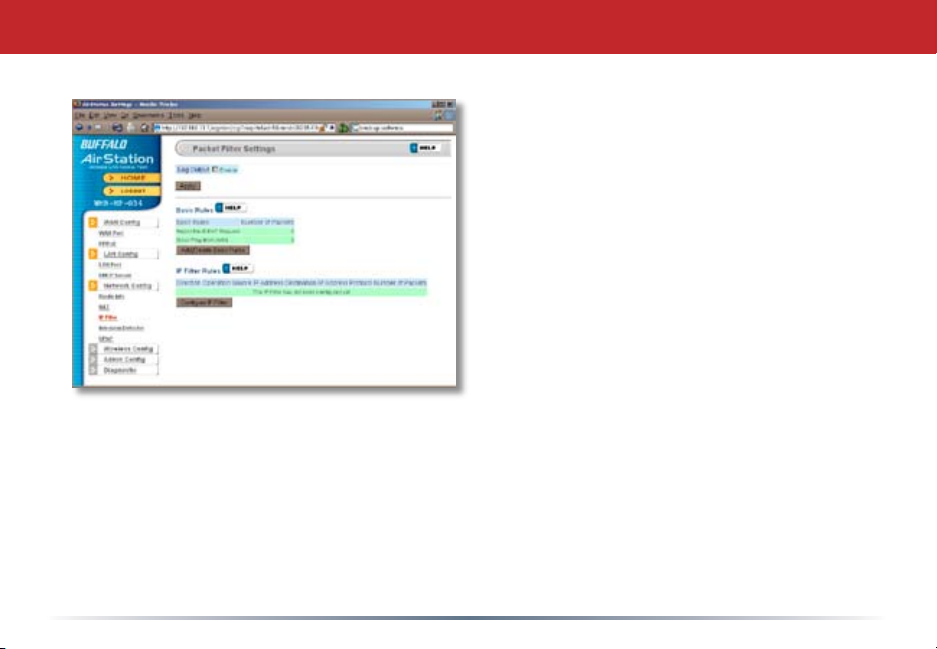
IP Filter
Your AirStation comes pre-congured
with basic rules. You may choose which
of these to use by clicking on Add/Delete
Basic Rules and turning to page 36.
To make a custom rule, click on Congure
IP Filter (page 37).
35
Page 36
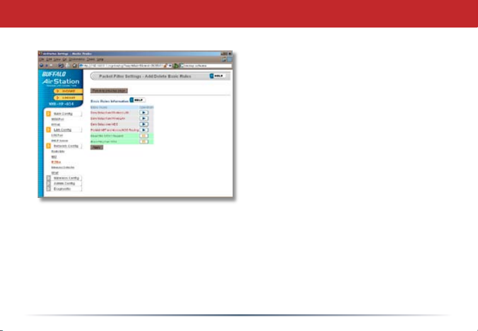
IP Filter (Add/Delete Basic Rules)
Get here by clicking on Add/Delete Basic
Rules (see page 35). You may choose which
of AirStation’s precongured basic rules
are enabled or disabled. Active rules are
displayed with a green background, and
disabled rules are shown in red. Choose
the rules you want to use by clicking under
Operation. When your choices are complete,
click on Initialize.
36
Page 37
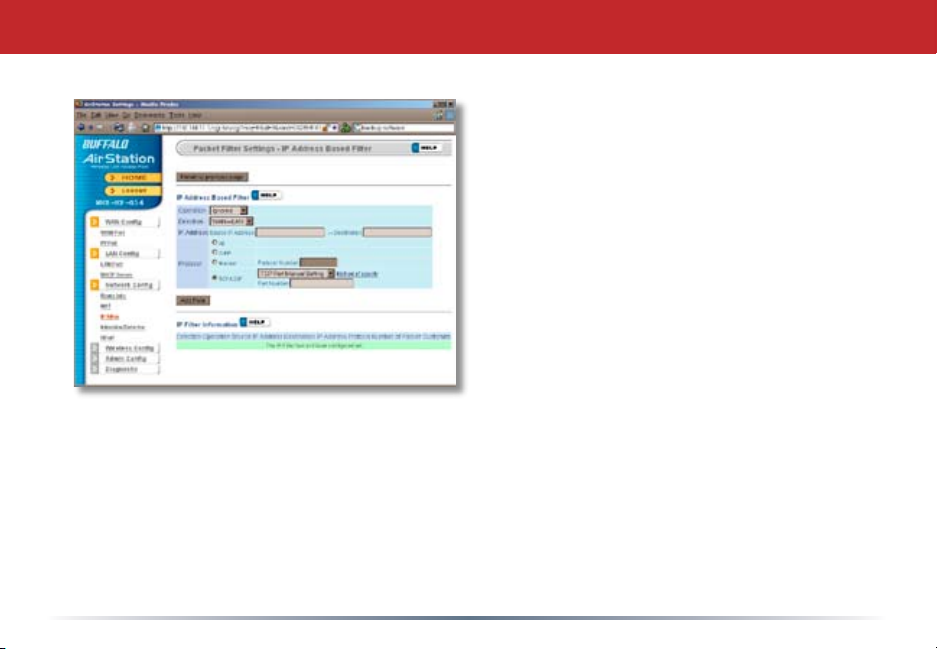
IP Filter (Congure IP Filter)
Clicking on Congure IP Filter from the IP
lter page (page 35) will bring you to this
page, where you can make your own rules.
Click Add Rule when you have each rule
congured the way you want it.
37
Page 38
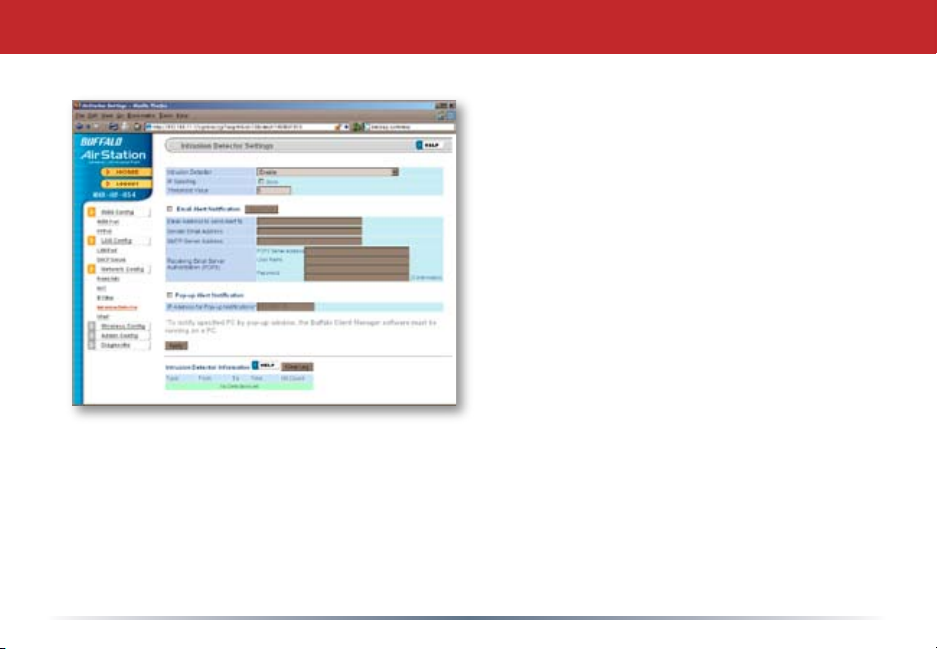
Network Conguration (Intrusion Detector)
To enable intrusion detector, choose
Enable or Enable (Apply packet lter rules)
from the Intrusion Detector drop-down
box. If packet lter rules are applied,
packets will be ltered with packet lter
rules before Intrusion Detector is applied.
Blocking IP spoong blocks packets from
devices using an IP address that is not
their own.
In the Threshold Value box, enter the
number of times an event has to occur
before you receive notication.
To congure your email alerts, enter your
email address and mail server information.
You may make up a sender email address,
such as “[email protected]”. Alert emails will appear to come from this address.
Intrusion detector also blocks unauthorized access attempts and suspicious trafc from
WAN-side devices (the internet).
38
Page 39
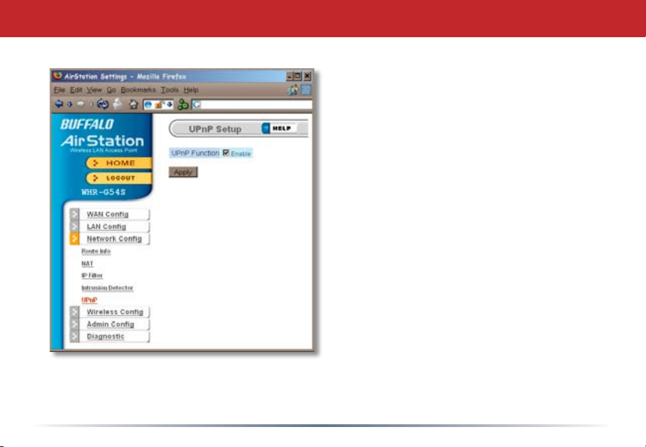
UPnP
You may disable Universal Plug and
Play functionality by unchecking
Enable here. Note that Windows (MSN)
Messenger will not function correctly
with UPnP disabled.
39
Page 40
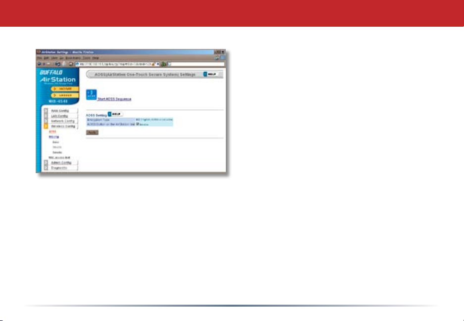
AOSS
Clicking Start AOSS Sequence has the same
function as pushing the AOSS button on the
router: it initiates the AOSS process.
If all your clients support AOSS, it’s very
simple to set them up. Press the AOSS
button on the router, or the one on this
page, and then push the AOSS button on
the client device.
Each client device will have to be set up
seperately. Wait for each AOSS process to
nish before starting the next one.
Consult your client device’s documentation
for the location of its AOSS button.
40
Page 41
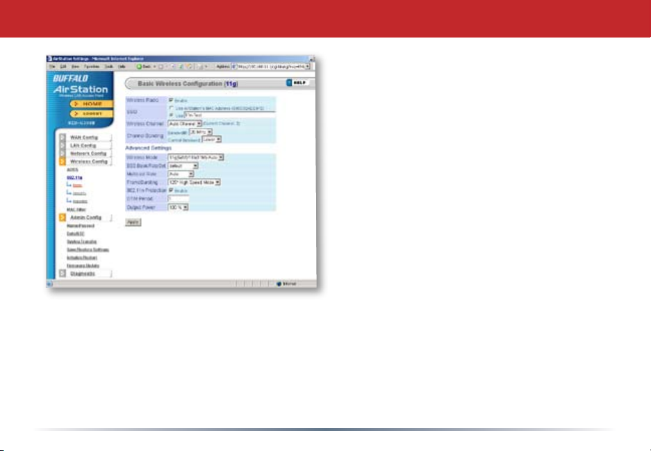
802.11a (Basic)
The SSID or network name can be changed
by entering a custom SSID and pressing
the Apply button.
41
Page 42
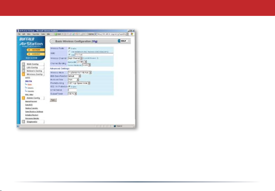
802.11a (Advanced)
If y ou h a ve a mi xed m ode net w ork,
w i t h D r a f t - N , 802.11a clients, i t ’
s r ecom men ded tha t y ou c hec k 1 1 n
prote ction to ensur e t hat s low er 11 a
clients connect properly.
42
Page 43
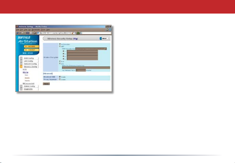
802.11a (Security)
Buf fal o r eco mme nds th at yo u c h oos e
th e st rongest fo rm o f en cryptio n th at’s
supported by all your client devices.
• WEP is a lot be tter than nothing, and
almost every wireless device ever made
supports it.
• TKIP is slower than WEP but much more
secure.
• AES is the most secure of all, and the
quickest as well. Use it if you can.
Setting the key renewal period too short
can decrease network performance.
By default, the AirStation broadcasts its SSID. This makes it easier for clients to connect
to the AirStation. To disable broadcasting, uncheck this box.
Privacy Seperator prevents wireless clients from being able to browse each other’s
computers. Check Enable to turn it on.
43
Page 44
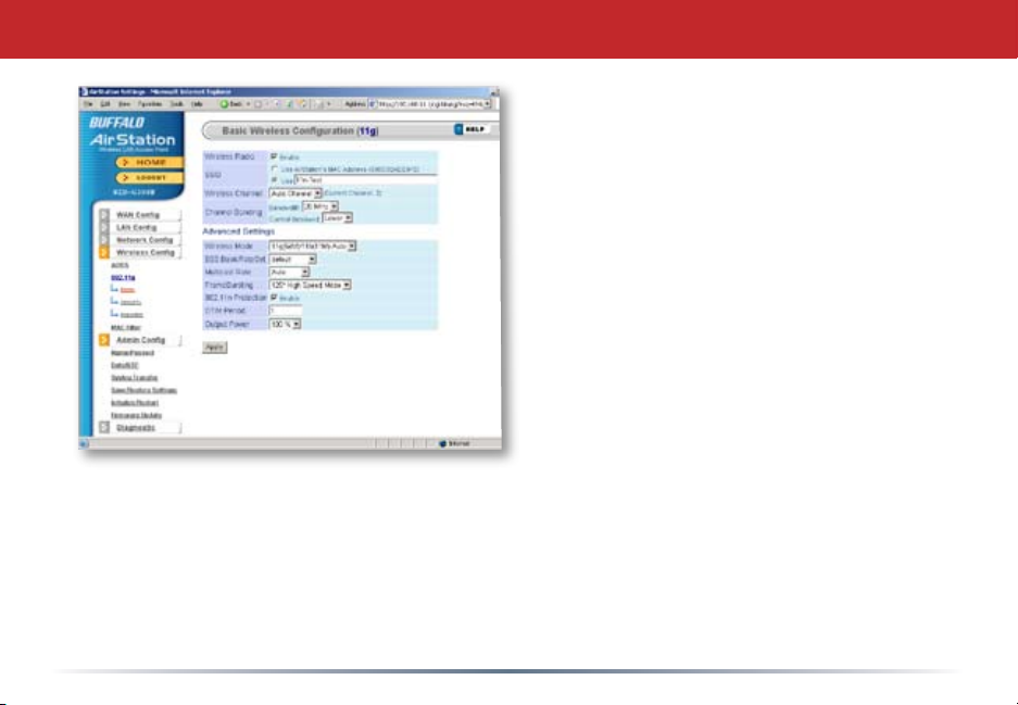
802.11g (Basic)
The SSID is the name of your wireless
network. This is what you’ll see
when performing a wireless scan or
survey from a wireless client. You
may change this to something easy to
remember, like “MYNETWORK”.
Channel Selection - You may nd it
necessary to change the AirStation’s
channel to avoid interference with
other 2.4 Ghz sources, such as
cordless phones, neighboring Wi-Fi
networks, baby monitors, etc. By
default, the Auto Channel mode will
attempt to locate the clearest channel
possible.
Channel Bonding modes are specic for Draft-N. The 20 MHz mode uses less
available wireless bandwith, which results in less interference to other 2.4 GHz
wireless devices as well as slower wireless transfer speeds. The 40 MHz mode
uses more bandwith, resulting in potentially more interference but signicantly
more performance. Control Sideband instructs the AirStation to use channels
towards the lower end of the spectrum or the higher end.
44
Page 45
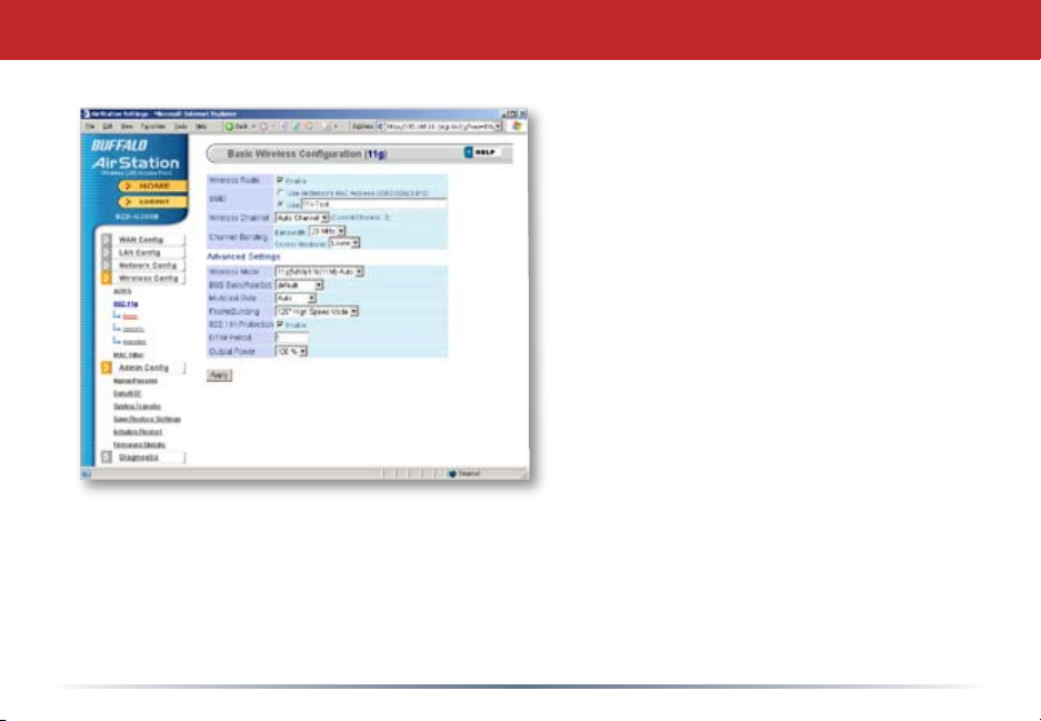
802.11g (Advanced)
If you have a mixed mode network, with
Draft-N, 802.11b and 802.11g clients,
it’s recommended that you check 11n
protection to ensure that slower 11b and
11g clients connect properly.
Choosing Auto for Wireless mode lets
Draft-N, 802.11b and 802.11g clients
connect to the network. If you would
prefer to allow only one of the modes to
connect, you have those options as well.
45
Page 46
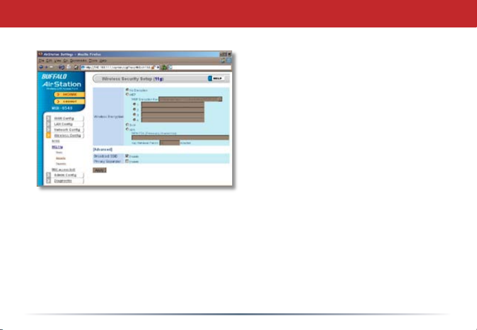
802.11g (Security)
Buffalo recommends that you choose
the strongest form of encryption that’s
supported by all your client devices.
• WEP is a lot better than nothing, and
almost every wireless device ever made
supports it.
• TKIP is slower than WEP but much more
secure.
• AES is the most secure of all, and the
quickest as well. Use it if you can.
Setting the key renewal period too short
can decrease network performance.
By default, the AirStation broadcasts its SSID. This makes it easier for clients to connect
to the AirStation. To disable broadcasting, uncheck this box.
Privacy Seperator prevents wireless clients from being able to browse each other’s
computers. Check Enable to turn it on.
46
Page 47
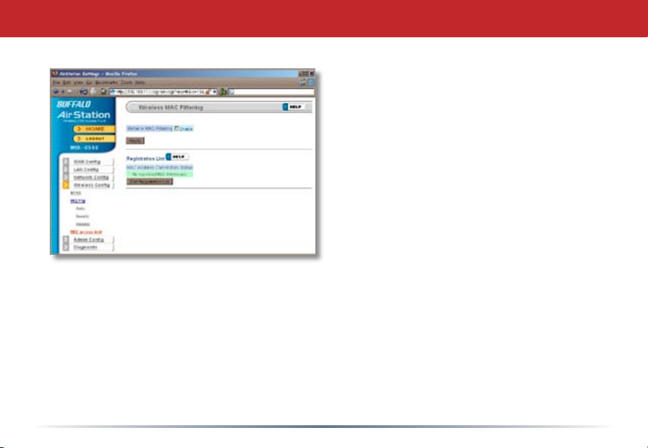
MAC Access Limit
To setup a bridge between two or more
wireless access points, select Enable
and click on Apply.
47
Page 48
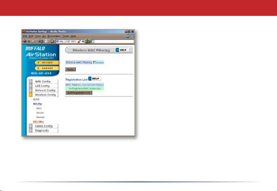
MAC Access Limit (Edit Registration List)
You may limit access to your wireless
network to specic computers.
Computers not listed on your MAC
Registration List will not be able to
connect to the network. If you enable
this, click Edit Registration List to add
MAC addresses to your registration list.
Enter a MAC address and click Apply
for each client that’s going to be
accessing the network.
48
Page 49
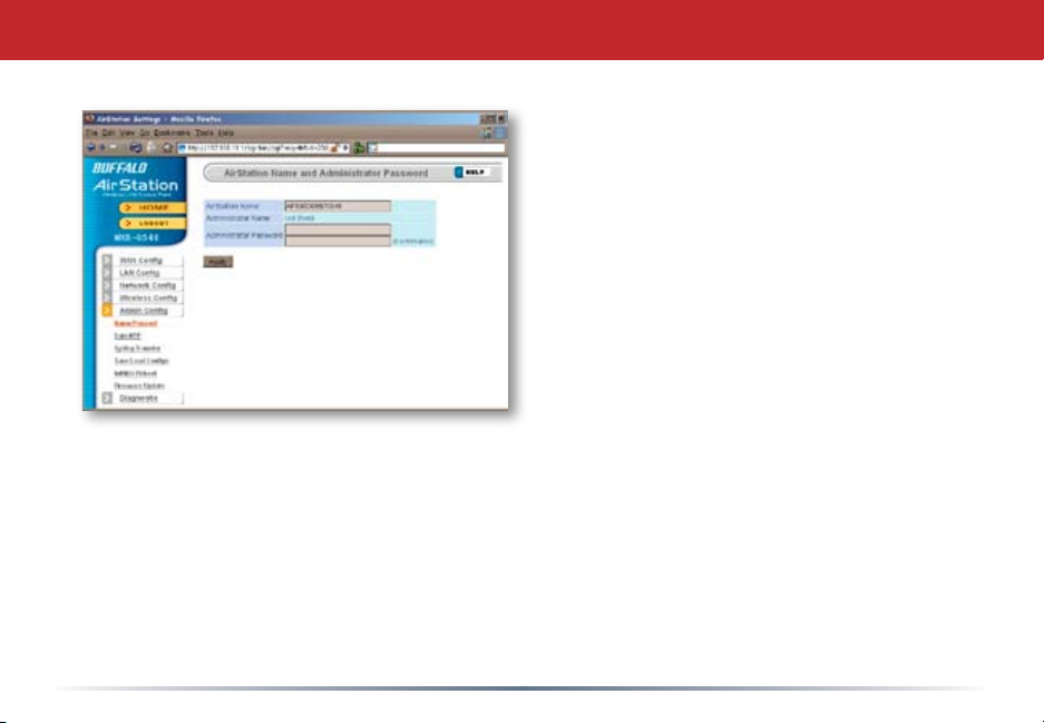
Admin Conguration (Name/Password)
Here, you can change your AirStation’s
name on your network and the
administrator password. The name of
the administrator account is xed as
“root”. If you have many AirStations on
your network, having clear, descriptive
names for each can make them much
easier to administrate.
49
Page 50
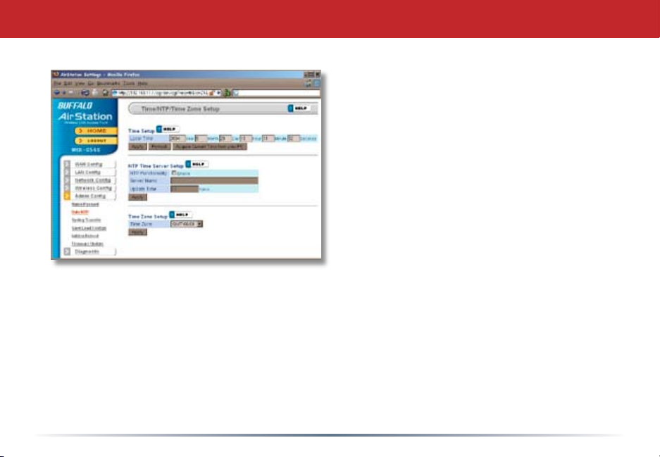
Admin Cong (Date/NTP)
You may set the time and date on your
AirStation by entering it manually, and then
clicking Apply.
You may also click Acquire Current Time from
your PC to set time and date automatically
to match the PC you’re using to set it up.
If you have an NTP time server on your
network, Enable NTP functionality and enter
your NTP Server Name. Choose how often
you want time updated and click Apply.
If you’re setting time manually, you’ll need
to select your Time Zone and click Apply.
50
Page 51
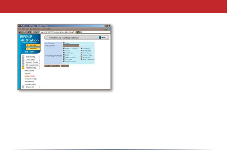
Syslog Transfer
If you have a syslog server on your
network, you may send logs to it.
Check Enable to have logs transferred.
Enter the address of your Syslog
Server, check the logs you want
transferred, and click Apply.
51
Page 52
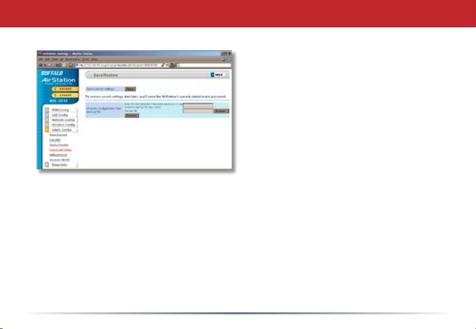
Save/Load Conguration
Once your AirStation’s congured
the way you want it, you can save
the conguration here. You’ll need
the current administrator password
to restore the conguration from the
backup le later.
Click Help at the top right corner
of the page for more information on
backing up and recovering system
conguration les.
52
Page 53
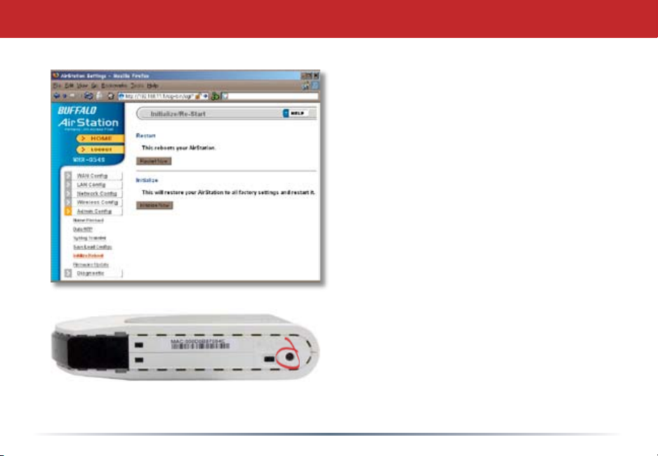
Initialize/Reboot
Click Restart Now to restart your
AirStation. Click Initialize Now to
restore your AirStation to factory
defaults and restart it.
You may also initialize your AirStation
by holding down the Init button on the
bottom of the router for 3 seconds.
53
Page 54
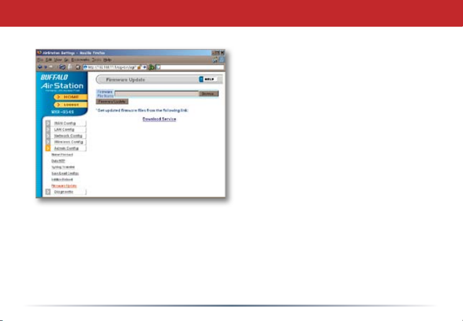
Firmware Update
Click Browse to select your rmware
update le. Then, click the Firmware
Update button to update rmware.
Firmware Update may take several
minutes to complete. Do not power
down the router until Firmware
Update is nished and the diag light
on the front of the router has stopped
blinking.
When available, updated rmware
may be downloaded from
www.buffalotech.com.
54
Page 55
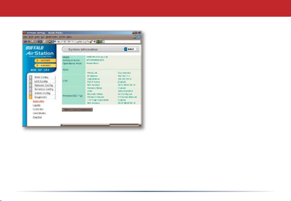
System Information
The System Information page lists all the
setup information for your AirStation. It
can be very handy for setting up clients
that don’t support AOSS.
55
Page 56
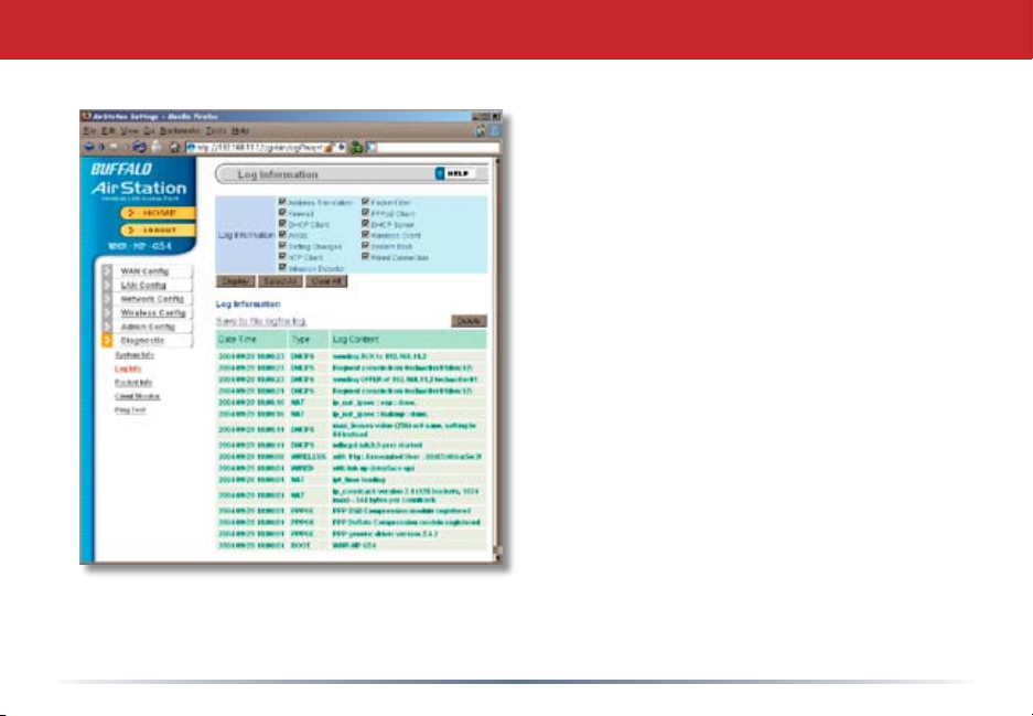
Log Information
Here you can choose what information
gets logged and see recent log entries.
56
Page 57
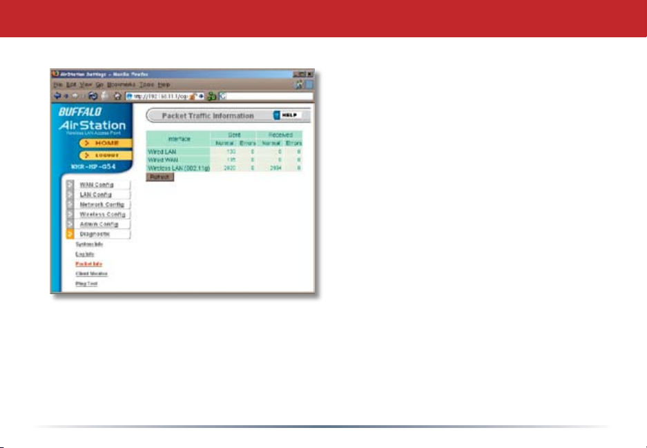
Packet Trafc Information
Here, you can see the packets and
errors for each of your networks.
57
Page 58
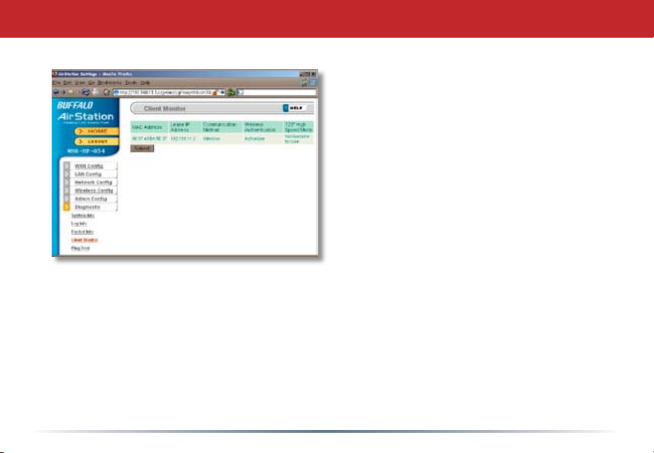
Client Monitor
Client Monitor shows you a list of all
clients currently connected to the
wireless network.
58
Page 59
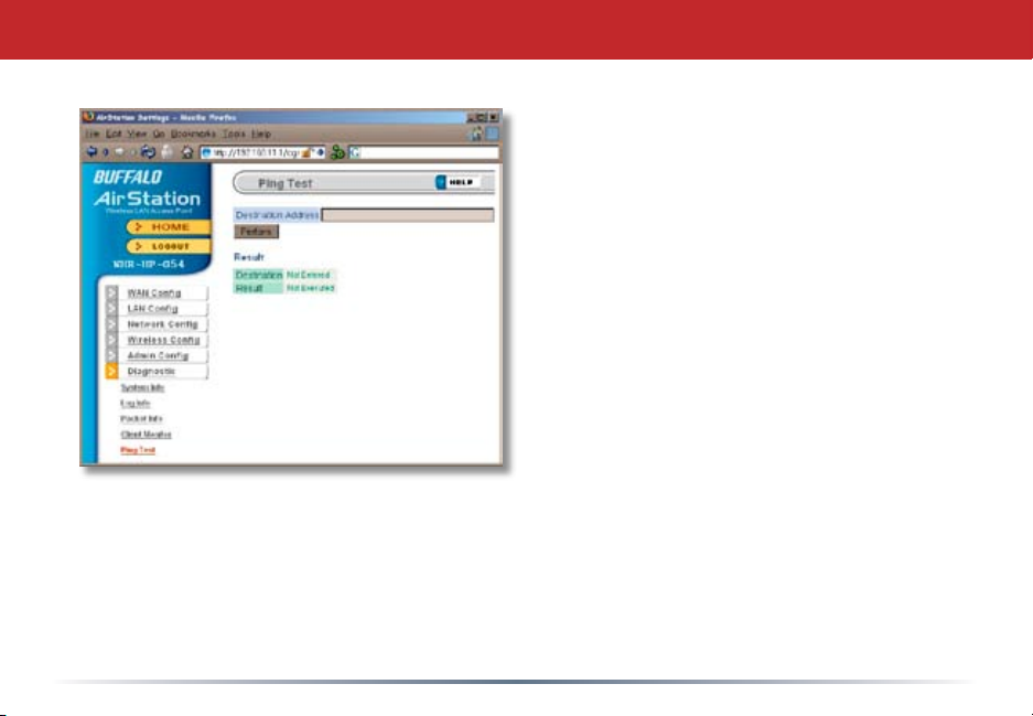
Ping Test
To perform a Ping test, enter a target
(such as 192.168.11.2 or www.
buffalotech.com) and click Execute.
Successful pings return “64 bytes
from . . .” messages. If the ping
returns “Connection failed” or other
errors, something is preventing you
from communicating successfully with
your target.
59
Page 60

Connecting to a Preexisting Network
Add an AirStation without changing your existing LAN conguration
1. Set the AirStation into Access Point Mode by moving the switch on the bottom from
AUTO to BRI.
2. Connect one of the AirStation’s LAN ports to an existing router or switch on your
network. Nothing should be plugged into the WAN port.
3. Open LAN Settings - LAN Port Settings and congure the following settings:
IP Address =[192.168.11.1] (Specify an unused network address from the existing
LAN.)
Subnet Mask=[255.255.255.0] (Use the same Subnet Mask as the existing LAN.)
DHCP Server Function=[Disable]
4. Restart PC.
60
Page 61

Specications
For more information, FAQ’s, and updates, consult the AirStation website at
http://www.buffalotech.com.
WZR-AG300NH AirStation Specications
Physical Specications
Dimensions 8.1 x 7.0 x 2.0 in. (210 x 175 x 50mm)
Weight 19.0 oz. lb. (540g)
Temperature & Humidity
Operation 0˚ to 40˚ C
Maximum humidity 85%
Transit/Storage 0˚ to 40˚ C maximum humidity 85% (no condensation)
Power Characteristics
Power Supply: 100-240V AC Universal, 50/60 Hz
Power Consumption about 10 Watts (Max)
61
Page 62

Specications
Regulatory Information
Wireless communication is often subject to local radio regulations. Although AirStation
wireless networking products have been designed for operation in the license-free 2.4 GHz
band, local radio regulations may impose limitations on the use of wireless communication
equipment.
Network Compatability
Draft-N support built off of the Draft Specication 1.0 for 802.11n.
IEEE802.11a/g/b Standard for Wireless LANs.
Host Operating System
Microsoft Windows® 98SE/ME/NT4.0/2000/XP, Unix, Linux and MacOS
Media Access Protocol
Wired - CSMD/CD (Collision Detection)
Wireless - CSMD/CA (Collision Avoidance) with Acknowledgment (ACK)
62
Page 63

Specications
AirStation IEEE 802.11 Channel Sets
The range of the wireless signal is related to the Transmit Rate of the wireless
communication. Communications at a lower Transmit range may travel longer distances.
Center Channel ID FCC
1 2412 2 2417 3 2422 4 2427 5 2432 6 2437 7 2442 8 2447 9 2452 10 2457
11 2462 11 default channel
63
Page 64

Troubleshooting
Common Problems
• Out of range, client cannot connect to the AirStation.
• Conguration mismatch, client cannot connect to the AirStation.
• Absence or conict with the Client Driver.
• Conict of another device with the AirStation hardware.
LED Activity
Monitoring LED activity helps identify problems.
• Power LED should be Green,
• Wireless LED should be Green if the line is active. If is it blinking Green, wireless
communication is active.
• Ethernet LED should be Green (100Mbps) or Amber (10Mbps) while the communication
is active.
• The Red Diag LED will ash during boot and rmware updates.
DIAG LED Activity
Unplug the power for three seconds. Plug the power back in to monitor the Diag LEDs
during start-up.
64
Page 65
Troubleshooting
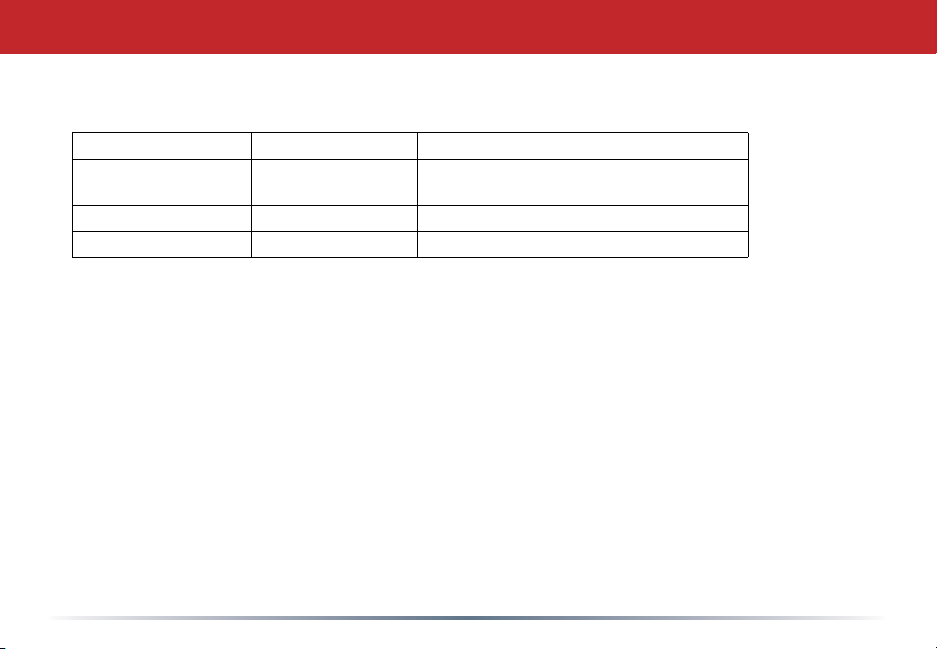
DIAG LED Activity Table
DIAG LED Display Time Description/Action
Continuous Red Starting RAM Error Red ash, 2 times Starting Flash
ROM Error
Red ash, 3 times Starting A problem on the wired LAN side
Red ash, 4 times Starting A problem on the wireless LAN side
LEDs Work But Client PC Cannot Connect to Network
If the LEDs indicate that the network is working properly (Power LED is on, Transmit/
Receive LED blinks), check the TCP/IP settings of the network.
Changing Client TCP/IP Settings in Windows
Consult the LAN Administrator for correct TCP/IP settings.
To add or change TCP/IP Settings:
1. On the Windows task bar, click Start.
2. Select Settings, then Control Panel.
3. Double-click on the Network icon to view Network Properties.
4. From the list of installed components, verify the TCP/IP => wireless LAN adapter
protocol is installed.
65
Page 66

Troubleshooting
• If the wireless adapter protocol is not yet installed, click the Add button and select
the TCP/IP protocol from the list. Refer to Windows Help for more information.
• If the wireless adapter protocol is installed, select the protocol and click the
Properties button. Verify that the parameters match the settings provided by your
LAN Administrator. Make changes if necessary, and click OK.
5. If prompted, restart your computer.
Other Problems
Please refer to www.buffalotech.com for further reference materials.
66
Page 67

Glossary
10BaseT: 802.3 based Ethernet network
that uses UTP (Unshielded twisted pair)
cable and a star topology. 10 Mbps data
tansmission speed.
100BaseT: 802.3 based Ethernet network
that uses UTP (Unshielded twisted pair)
cable and a star topology. 100 Mbps data
tansmission speed.
1000BaseT: 802.3 based Ethernet
network that uses UTP (Unshielded twisted
pair) cable and a star topology. 1000 Mbps
data tansmission speed.
802.1x: The standard for wireless LAN
authentication used between an AP and a
client. 802.1x with EAP will initiate key
handling.
Access Point: A hardware device that acts
as a communication hub for Clients (users
of wireless devices) to connect to a wired
LAN.
Ad-Hoc Network: A network based on
peer-to-peer communication rather than a
router, switch, or hub.
Bandwidth: The transmission capacity of
a computer or a communication channel,
usually stated in Megabits per second
(Mbps).
Bridge: A device which forwards trafc
between network segments with a common
network layer address, based on data link
layer information.
Client: A PC, workstation, or other device
that connects to a network wirelessly
through an Access Point.
Cross-Over Cable: A UTP cable that has its
transmit and receive pair crossed to allow
communications between two devices.
Default Gateway: The IP Address of either
the nearest router or server for the LAN.
67
Page 68

Glossary
Destination Address: The address portion
of a packet that identies the intended
recipient station.
DHCP (Dynamic Host Conguration
Protocol): Based on BOOTP, it uses a pool
of IP addresses, which it assigns to each
device connected to it, and retrieves the
address when the device becomes dormant
for a period of time.
DNS (Domain Name System): System
used to map readable machine names into
IP addresses.
Driver: Software that interfaces a
computer with a specic hardware device.
Dynamic IP Address: An IP address that
is automatically assigned to a client station
in a TCP/IP network, typically by a DHCP
server.
Ethernet: The most widely used
architecture for Local Area Networks
(LANs). It is a shared-media network
architecture. The IEEE 802.3 standard
details its functionality.
Ethernet cable: A wire similar to telephone
cable that carries signals between Ethernet
devices. It is designed to connect a single
device’s NIC to a router, switch, or hub.
See also Crossover cable.
File and Print Sharing: A Microsoft
application that allows computers on a
network to share les and printers.
Firmware: Computer programming
instructions that are stored in a readonly memory unit rather than being
implemented through software.
Frame: A xed block of data, transmitted
as a single entity. Also referred to as a
packet.
68
Page 69

Glossary
Full-Duplex: To transmit on the same
channel in both directions simultaneously.
Half-duplex: To transmit on the same
channel in both directions, one direction at
a time.
Hub: A device which allows connection
of computers and other devices to form a
LAN.
IEEE (Institute of Electrical and
Electronics Engineers): The professional
organization which promotes development
of electronics technology.
IP (Internet Protocol) Address: A unique
32-binary-digit number that identies each
sender or receiver of information sent in
packets.
Infrastructure: A wireless network or
other small network in which the wireless
network devices are made a part of the
network through the Access Point.
ISP (Internet Service Provider): A
company that provides access to the
Internet and other related services.
IV (Initialization Vector): The header
section of an encrypted message packet.
LAN (Local Area Network): A group
of computers and peripheral devices
connected to share resources.
LED (Light Emitting Diode): The lights
on a hardware device representing the
activity through the ports.
MAC (Medium Access Control) Address:
The unique number that distinguishes
every network interface card.
Mbps (Mega Bits Per Second): A
measurement of millions of bits per
second.
MDI/X (Media Dependent Interface/
Cross-over): Port on a network hub or
switch that crosses the incoming transmit
lines with the outgoing receive lines.
69
Page 70

Glossary
MHz (MegaHertz): One million cycles per
second.
NAT (Network Address Translation): An
internet standard that enables a LAN to
use one set of IP addresses for internal
trafc and a second set for external trafc.
NIC (Network Interface Card): An
expansion card connected to a computer
so the computer can be connected to a
network.
Packet: A block of data that is transferred
as a single unit, also called a frame or a
block.
Packet Filtering: Discarding unwanted
network trafc based on its originating
address or its type.
PCI (Peripheral Component
Interconnect): A bus that is connected
directly to the CPU.
PCMCIA (Personal Computer Memory Card
International Association) Card: Removable
module that adds features to a portable
computer.
Peer-to-peer: This simple network is formed by
connecting computers directly, without use of
routers or hubs. A crossover cable is plugged
into an Ethernet port in each computer,
connecting them directly.
Ping (Packet Internet Groper): An Internet
utility used to determine whether a particular
IP address is accessable.
Plug and Play: Hardware that, once physically
installed, nishes its installation automatically
and may immediately be used, as opposed
to hardware that requires further manual
conguration.
PoE (Power over Ethernet): A mechanism
to send DC power to a device using a CAT5
Ethernet cable.
70
Page 71

Glossary
PPPoE (Point-to-Point Protocol over
Ethernet): A specication for connecting
users on an Ethernet line to the Internet
through a common broadband medium.
Protocol: A standard way of exchanging
information between computers.
RADIUS (Remote Authentication Dial
In User Service): A server that issues
authentication keys to clients.
RAM (Random Access Memory): Non-
permanent memory.
Repeater Hub: A device that collects,
strengthens and transmits information to
all connected devices, allowing the network
to be extended to accommodate additional
workstations. See also Bridge.
RC4: The encryption algorithm used by
WEP.
RJ-45 connector: An 8-pin connector
used between a twisted pair cable and a
data transmission device.
ROM (Read Only Memory): Memory
hardware that allows fast access to
permanently stored data but prevents
addition to or modication of the data.
Router: A device in a network that
handles message transfer between
computers. Similar to a hub, but with
added functionality and efciency.
Roaming: The ability to use a wireless
device while moving from one access point
to another without losing the connection.
Server: Any computer that makes les or
peripheral devices available to users of the
network and has a resident Network OS.
SMTP (Simple Mail Transfer Protocol):
The protocol used to dene and deliver
electronic mail (E-mail) from one location
to another.
71
Page 72

Glossary
SNMP (Simple Network Management
Protocol: An application layer protocol
that outlines the formal structure for
communication among network devices.
Static IP Address: A permanent IP
address is assigned to a node in a TCP/IP
network. Also known as global IP.
STP (Shielded Twisted Pair): Twisted Pair
cable wrapped in a metal sheath to provide
extra protection from external interfering
signals.
Subnet Mask: An eight-byte address
divided into 4 parts separated by periods.
TCP/IP (Transmission Control Protocol/
Internet Protocol: Protocol used by
computers when communicating across
the Internet or Intranet.
TKIP (Temporal Key Integrity Protocol):
An encryption method replacing WEP.
TKIP uses random IV and frequent key
exchanges.
Topology: The shape of a LAN (Local Area
Network) or other communications system.
Twisted Pair: Cable that comprises 2
or more pair of insulated wires twisted
together.
UDP (User Datagram Protocol): A
communication method (protocol)
that offers a limited amount of service
when messages are exchanged between
computers in a network. UDP is used as
an alternative to TCP/IP.
Uplink: Link to the next level up in a
communication hierarchy.
UTP (Unshielded Twisted Pair) cable:
Two or more unshielded wires twisted
together to form a cable.
WAN (Wide Area Network): A networking
system covering a wide geographical area.
72
Page 73

Glossary
WEP (Wired Equivalent Privacy): A
security protocol for wireless local area
networks dened in the 802.11b standard,
using a 64 bit or 128 bit key. WEP was
designed to provide the same level of
security as that of a wired LAN. However, it
has been found that WEP is not as secure
as once believed.
Web Browser: A software program that
allows viewing of web pages.
Wi-Fi (Wireless Fidelity): An organization
that tests and assures interoperability
among WLAN devices.
Wire Speed: The maximum speed at
which a given packet can be transferred
using Ethernet and Fast Ethernet standard
specications.
WLAN (Wireless LAN): A LAN topology
using wireless devices.
VPN (Virtual Private Network): A security
method to connect remote LAN users to a
corporate LAN system.
73
Page 74

FCC / CE / R&TTE
Federal Communication Commission Interference Statement
This equipment has been tested and found to comply with the limits for a Class B digital
device, pursuant to Part 15 of the FCC Rules. These limits are designed to provide reasonable
protection against harmful interference in a residential installation. This equipment generates,
uses and can radiate radio frequency energy and, if not installed and used in accordance with
the instructions, may cause harmful interference to radio communications. However, there
is no guarantee that interference will not occur in a particular installation. If this equipment
does cause harmful interference to radio or television reception, which can be determined by
turning the equipment off and on, the user is encouraged to try to correct the interference by
one of the following measures:
• Reorient or relocate the receiving antenna.
• Increase the separation between the equipment and receiver.
• Connect the equipment into an outlet on a circuit different from that to which the receiver
is connected.
• Consult the dealer or an experienced radio/TV technician for help.
FCC Caution: To assure continued compliance, (example - use only shielded interface cables
when connecting to computer or peripheral devices). Any changes or modifications not expressly
approved by the party responsible for compliance could void the user’s authority to operate
this equipment.
This device complies with Part 15 of the FCC Rules. Operation is subject to the following two
conditions: (1) This device may not cause harmful interference, and (2) this device must accept
any interference received, including interference that may cause undesired operation.
74
Page 75
FCC / CE / R&TTE
FCC RF Radiation Exposure Statement:
This equipment complies with FCC RF radiation exposure limits set forth for an uncontrolled
environment. This equipment should be installed and operated with a minimum distance
of 20 centimeters between the radiator and your body.
This transmitter must not be co-located or operating in conjunction with any other antenna
or transmitter.
Europe – EU Declaration of Conformity
This device complies with the essential requirements of the R&TTE Directive 1999/5/EC.
The following test methods have been applied in order to prove presumption of compliance
with the R&TTE Directive 1999/5/EC:
•
EN 60950: 2000
Safety of Information Technology Equipment
•
EN 300 328-2 V1.2.1 (2001-12)
Technical requirements for spread-spectrum radio equipment
•
EN 301 489-17 V1.1.1 (2000-09)
EMC requirements for spread-spectrum radio equipment
75
Page 76

FCC / CE / R&TTE
Safety
This equipment is designed with the utmost care for the safety of those who install and
use it. However, special attention must be paid to the dangers of electric shock and static
electricity when working with electrical equipment. All guidelines of this manual and of
the computer manufacturer must therefore be allowed at all times to ensure the safe use
of the equipment.
Intended use
This device is a 2.4 GHz and 5 GHz wireless LAN transceiver, intended for indoor home
and ofce use in USA, Canada, all EU and EFTA member states.
EU Countries intended for use
This device is intended for indoor Home and ofce use in the following countries:
Austria, Belgium, Germany, Denmark, Spain, Greece, France, Finland, Italy, Ireland,
Luxembourg, The Netherlands, Portugal, Sweden, United Kingdom, Cyprus, Czech
Republic, Estonia, Hungry, Latvia, Lithuania, Malta, Poland, Slovak Republic and
Slovenia.
The device is also authorised for use in all EFTA member states Iceland, Liechtenstein,
Norway and Switzerland.
76
Page 77

FCC / CE / R&TTE
EU countries not intended for use
None
Potential restrictive use
This device is a 2.4 GHz and 5 GHz wireless LAN transceiver, intended for indoor home
and ofce use in all EU and EFTA member states, except in France, Belgium and Italy
where restrictive use applies.
In Italy the end-user should apply for a license at the national spectrum authorities in
order to obtain an authorization to use the device for setting up outdoor radio links.
In Belgium there is a restriction in outdoor use. The frequency range in which outdoor
operation in Belgium is permitted is 2460 – 2483.5 MHz.
In France only channels 10,11,12 and 13 are available.
This device may not be used for setting up outdoor radio links in France. For more
information see http://www.anfr.fr/ and/or http://www.art-telecom.fr
77
Page 78

Warranty Information
Buffalo Technology (Melco Inc.) products come with a two-year limited warranty from the
date of purchase. Buffalo Technology (Melco Inc.) warrants to the original purchaser the
product; good operating condition for the warranty period. This warranty does not include
non-Buffalo Technology (Melco Inc.) installed components. If the Buffalo product malfunctions
during the warranty period, Buffalo Technology/(Melco Inc.) will, replace the unit, provided
the unit has not been subjected to misuse, abuse, or non-Buffalo Technology/(Melco Inc.)
authorized alteration, modications or repair.
All expressed and implied warranties for the Buffalo Technology (Melco Inc) product line
including, but not limited to, the warranties of merchantability and tness of a particular
purpose are limited in duration to the above period.
Under no circumstances shall Buffalo Technology/(Melco Inc.) be liable in any way to the
user for damages, including any lost prots, lost savings or other incidental or consequential
damages arising out of the use of, or inability to use the Buffalo products.
In no event shall Buffalo Technology/(Melco Inc.) liability exceed the price paid for the product from direct, indirect, special, incidental, or consequential damages resulting from the
use of the product, its accompanying software, or its documentation. Buffalo Technology
(Melco Inc.) does not offer refunds for any product.
@ 2003-2006 Buffalo Technology (Melco, Inc.)
78
Page 79

Contact Information
Buffalo Technology (USA), Inc.
4030 West Braker Lane, Suite 120
Austin, TX 78759-5319
GENERAL INQUIRIES
Monday through Friday
8:30am-5:30pm CST
Direct: 512-794-8533 | Toll-free: 800-456-9799 | Fax: 512-794-8520 | Email:
TECHNICAL SUPPORT
North American Technical Support by phone is available 24 hours a day, 7 days a week.
79
Page 80

Contact Information
Buffalo Technology (Europe), Inc.
176 Buckingham Avenue,
Slough, Berkshire, SL1 4RD
United Kingdom
GENERAL INQUIRIES
Email: [email protected]
TECHNICAL SUPPORT
Technical Support in Europe is available between the hours of 9am-6pm (GMT) Monday to
Thursday and 9am-4:30pm (GMT) Friday for this product. Customers in Europe can obtain
Technical Support using the following information:
E-mail: [email protected] | Web: www.buffalo-technology.com
80
 Loading...