

Page 1
SECTION I–MAINTENANCE
SUBJECT PAGE NO.
1. Specifications . . . . . . . . . . . . . . . . . . . . . . . . . . . . . . . . . . . . . . . . . . . . . . . . . . . . . . . . . . . 3
2. Side Views. . . . . . . . . . . . . . . . . . . . . . . . . . . . . . . . . . . . . . . . . . . . . . . . . . . . . . . . . . . . . . 4
3. Fluid Requirements. . . . . . . . . . . . . . . . . . . . . . . . . . . . . . . . . . . . . . . . . . . . . . . . . . . . . . . 6
4. Clutch . . . . . . . . . . . . . . . . . . . . . . . . . . . . . . . . . . . . . . . . . . . . . . . . . . . . . . . . . . . . . . . . . 7
5. Rear Preload Adjustment . . . . . . . . . . . . . . . . . . . . . . . . . . . . . . . . . . . . . . . . . . . . . . . . . . 8
6. Ignition Timing. . . . . . . . . . . . . . . . . . . . . . . . . . . . . . . . . . . . . . . . . . . . . . . . . . . . . . . . . . . 9
This section explains procedures unique to 1997 model S1 Lightnings. Any procedures not found
in this supplement are covered in the 1996 S1 Lightning Service Manual (Part No. 99490-96Y).
1
Page 2
NOTES
2
Page 3
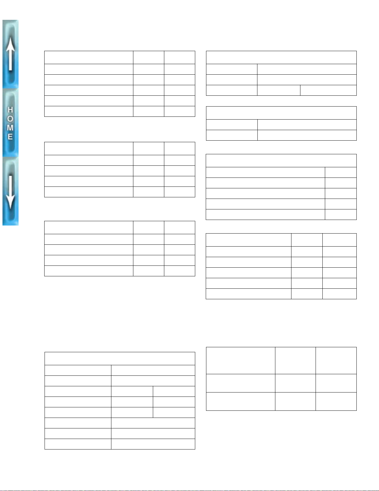
SPECIFICATIONS
DIMENSIONS IN. MM
I
IGNITION SYSTEM
Wheel base 55 1397
Overall length 79.5 2019
Overall width 30 762
Road clearance 5.2 132
Seat height 29.5 749
CAPACITIES U.S. LITERS
Fuel tank (including reserve) 4.0 gallons 15.14
Reserve 0.6 gallons 2.27
Oil tank 2.0 quarts 1.89
Transmission 1.0 quart 0.95
WEIGHT LBS. KG
S1 shipping weight 446 202
GVWR 820 372
GAWR - Front 340 154
GAWR - Rear 480 218
Spark plugs No. 6R12
Size 12 mm
Gap 0.038-0.045 in. 0.97-1.14 mm
TRANSMISSION
Type Constant Mesh, Foot Shift
Speeds 5 Forward
NUMBER OF SPROCKET TEETH
Engine 35
Clutch 56
Transmission 27
Rear wheel 61
Belt 128
TRANSMISSION GEAR RATIOS FINAL* OVERALL**
First (low) gear 2.69 9.717
Second gear 1.97 7.118
Third gear 1.43 5.180
NOTE
Gross Vehicle Weight Rating (GVWR) (maximum allowable
loaded vehicle weight) and corresponding Gross Axle Weight
Ratings (GAWR) are given on an information decal located on
the front frame steering head.
ENGINE
Number of cylinders 2
Type 4-Cycle, 45 Degree V-Type
Bore 3.498 in. 88.849 mm
Stroke 3.8125 in. 96.838 mm
Piston displacement 73.4 cu. in. 1203 cc
Compression ratio 10.0 to 1
Horsepower @ RPM 91 @ 5800
Torque ft-lb @ RPM 87 @ 5200
Fourth gear 1.18 4.269
Fifth (high) gear 1.00 3.615
*Final gear ratios indicate number of mainshaft revolutions
required to drive output sprocket one revolution.
**Overall gear ratios indicate number of engine revolutions
required to drive rear wheel one revolution.
PRESSURE
TIRE AND POSITION
Front-Dunlop Sportmax
Radial II 120/70 ZR 17
Rear-Dunlop Sportmax
Radial II 170/60 ZR 17
Do not inflate any tire beyond its maximum inflation
pressure as specified on tire sidewall. Overinflation may
cause tire to suddenly deflate leading to personal injury.
1
WARNING
FOR SOLO
RIDING
32 PSI
(2.2 bar)
36 PSI
(2.5 bar)
PRESSURE
AT GVWR
36 PSI
(2.5 bar)
38 PSI
(2.8 bar)
3
Page 4
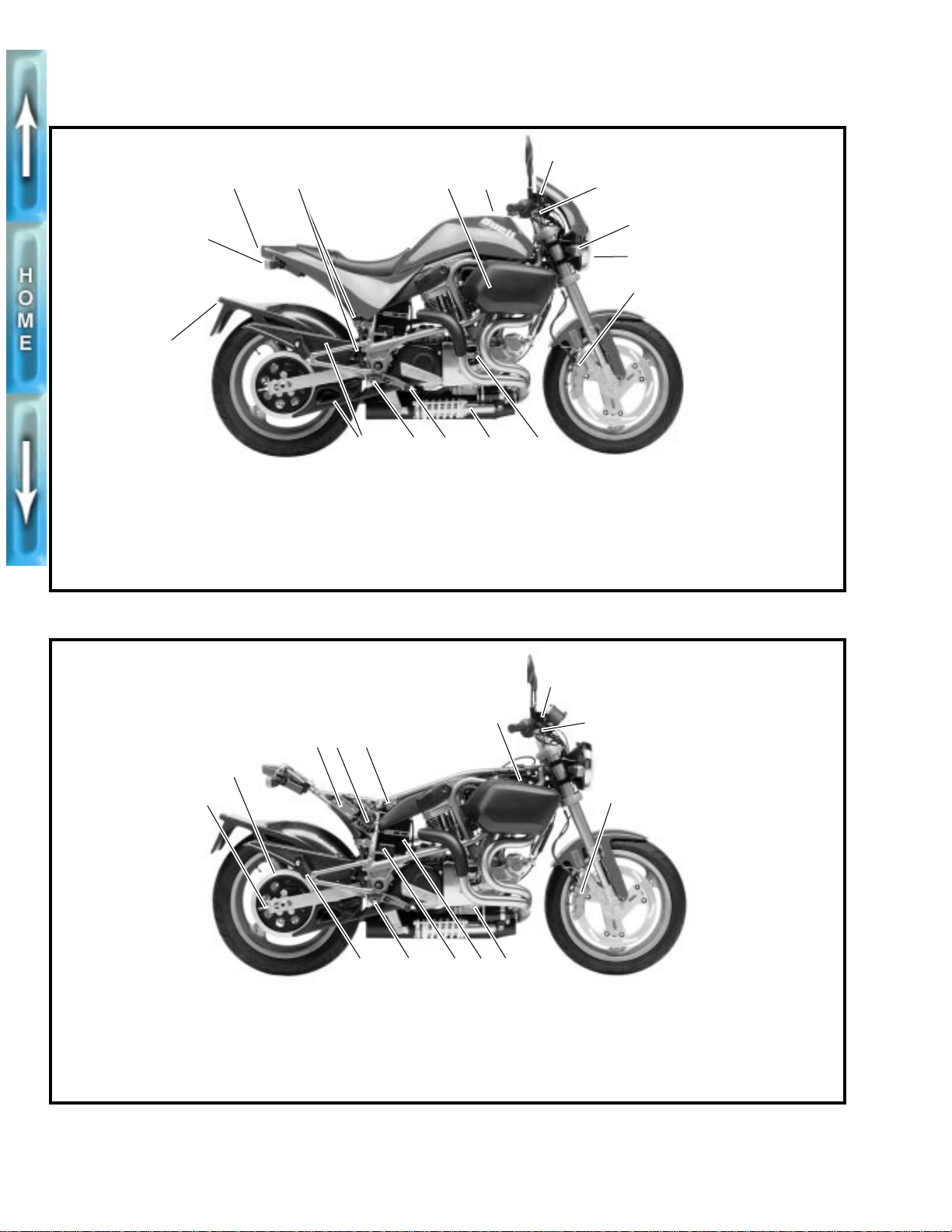
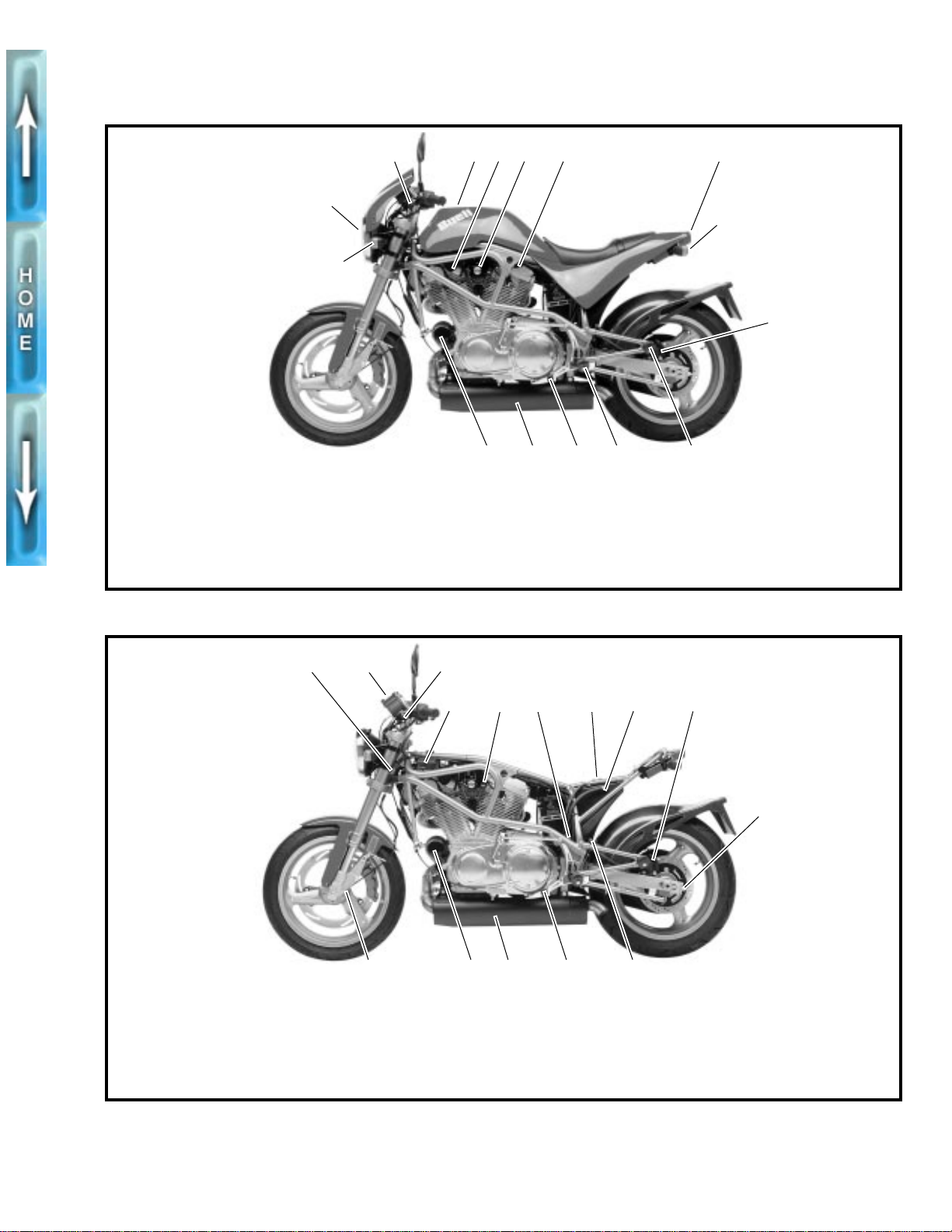
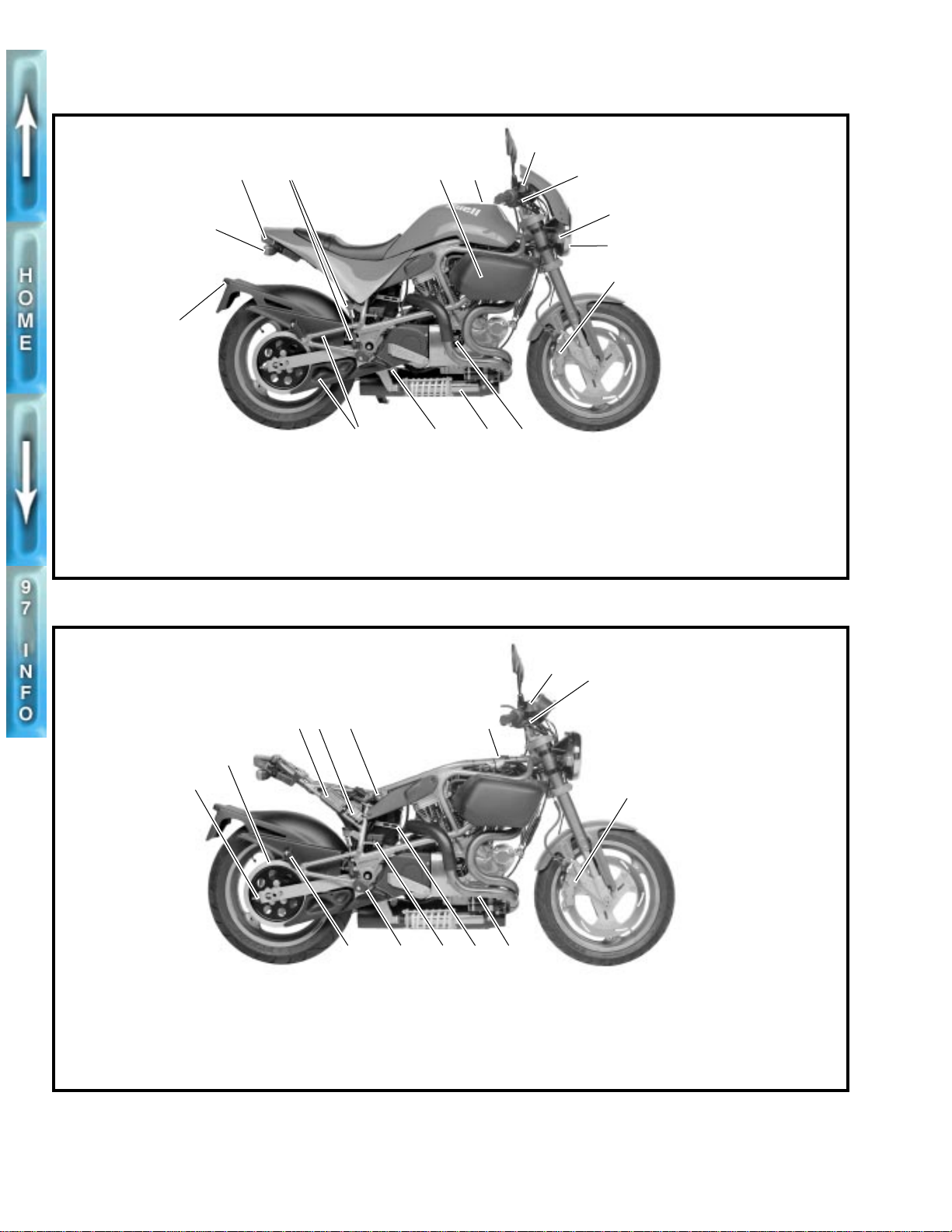
SIDE VIEWS
5806
1
16
1. Right rear turn signal
2. Tail/stop lamp
3. Rear brake master cylinder/
reservoir
4. Air cleaner cover
5. Fuel filler cap
32
6. Front brake master cylinder
7. Front brake hand lever
8. Right front turn signal
9. Headlamp
10. Front brake caliper
11. Timer cover
4
6
5
7
8
9
10
1112131415
12. Rear shock absorber
13. Rear brake pedal
14. Rider footrest
15. Belt guard(s)
16. License plate light
5808
2
1
1. Rear axle adjuster nut
2. Rear sprocket and secondary
drive belt
3. Ignition module
4. Fuse block and spare fuse
Figure 1. 1997 S1 Lightning, Right Side View
7
6
3
4 5
1011121314
5. Turn signal flasher
6. Remote idle adjuster
7. Front brake master cylinder
8. Front brake hand lever
9. Front brake caliper
10. Oil pump
11. Battery
12. Voltage regulator
13. Rider footrest
14. Passenger footrest
8
9
Figure 2. 1997 S1 Lightning, Right Side View (Body Removed)
4
Page 5
5807
3 6 7 8
54
2
9
1
10
1112131415
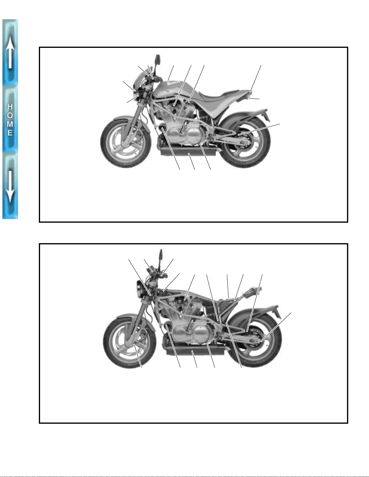
1. Left front turn signal
2. Headlamp
3. Clutch hand lever
4. Fuel filler cap
5. Horn
5809
6. Ignition/headlamp key switch
7. Fuel supply valve
8. Tail/stop lamp
9. Left rear turn signal
10. Rear brake caliper
Figure 3. 1997 S1 Lightning, Left Side View
2 31
6 84
5 9
7
11. Passenger footrest
12. Rider footrest
13. Gear shift lever
14. Exhaust muffler
15. Oil filter
10
1. Steering head lock
2. Instruments
3. Clutch hand lever
4. Ignition coil
5. Enrichener knob
15
6. Starter relay
7. Oil filler plug/dipstick
8. Oil tank
9. Rear brake caliper
10. Rear axle adjuster nut
Figure 4. 1997 S1 Lightning, Left Side View (Body Removed)
11121314
11. Oil tank drain hose
12. Gear shift lever
13. Exhaust muffler
14. Oil filter
15. Speedometer drive
5
Page 6
FLUID REQUIREMENTS
GENERAL
United States System
Unless otherwise specified,
in this Service Manual are expressed in United States
(U.S.) units-of-measure
●
1 pint (U.S.) = 16 fluid ounces (U.S.)
●
1 quart (U.S.) = 2 pints (U.S.) = 32 fl. oz. (U.S.)
●
1 gallon (U.S.) = 4 quarts (U.S.) = 128 fl. oz. (U.S.)
all fluid volume measurements
. See below:
Metric System
Fluid volume measurements in this Service Manual include
the metric system equivalents. In the metric system, 1 liter
(L) = 1,000 milliliters (mL). Should you need to convert from
U.S. units-of-measure to metric units-of-measure (or vice
versa), refer to the following:
●
fluid ounces (U.S.) x 29.574 = milliliters
●
pints (U.S.) x 0.473 = liters
●
quarts (U.S.) x 0.946 = liters
gallons (U.S.) x 3.785 = liters
●
milliliters x 0.0338 = fluid ounces (U.S.)
●
●
liters x 2.114 = pints (U.S.)
●
liters x 1.057 = quarts (U.S.)
liters x 0.264 = gallons (U.S.)
●
STEERING HEAD BEARING GREASE
Use WHEEL BEARING GREASE (Part No. 99855-89).
BRAKE FLUID
FRONT FORK OIL
Use only WP FORK OIL, 5 WEIGHT.
FUEL
Use a good quality leaded or unleaded gasoline (91 pump
octane or higher). Pump octane is the octane number usually
shown on the gas pump.
ENGINE OIL
Use the proper grade of oil for the lowest temperature
expected before the next oil change.
Table 1. Recommended Oil Grades
°
F
°
°
°
COLD
WEATHER
STARTS
BELOW
50° F
Excellent
Good
Poor
Poor
HARLEY-
DAVIDSON TYPE
H.D. Multi-Grade
H.D. Multi-Grade
H.D. Regular Heavy
H.D. Extra Heavy
VISCOSITY
SAE
10W40
SAE
20W50
SAE
50
SAE
60
HARLEY-
DAVIDSON
RATING
HD 240
HD 240
HD 240
HD 240
LOWEST
AMBIENT
TEMP.
Below 40
(4°C)
Above 40
(4°C)
Above 60
(16°C)
Above 80
(27°C)
PRIMARY DRIVE/TRANSMISSION LUBRICANT
Use only SPORT-TRANS FLUID (Part No. 98854-96 quart
size or Part No. 98855-96 gallon size).
1
WARNING
D.O.T. 5 SILICONE HYDRAULIC BRAKE FLUID can cause
eye irritation. In case of contact with eyes, flush with
plenty of water and get medical attention. KEEP BRAKE
FLUID OUT OF THE REACH OF CHILDREN!
Use only D.O.T. 5 SILICONE HYDRAULIC BRAKE FLUID
(Part No. 99902-77).
6
Page 7
CLUTCH
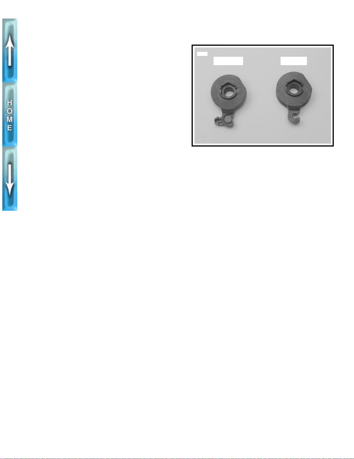
MODEL YEAR CHANGE
See Figure 5. All 1997 model year motorcycles use the new
style clutch release ramp introduced on late 1996 vehicles.
The clutch adjustment and lever freeplay procedures remain
the same. The change was made to provide additional clearance between the coupler and the primary cover.
5671
New style Old style
Figure 5. Ramp Change
7
Page 8
REAR PRELOAD ADJUSTMENT
GENERAL
Rear suspension spring preload must be adjusted before any
other adjustments can be attempted. This adjustment assures
that the rear suspension has the proper amount of travel.
Spring preload is the most important suspension adjustment
on the S1 Lightning. Improper preload will adversely affect
both the handling and motorcycle ride. Correct preload setting will result in motorcycle handling that suits the rider’s size
and weight.
ADJUSTMENT
You will need three people to carry out this adjustment.
1. Verify correct front and rear tire pressure. See SPECIFI-
CATIONS on page 3.
2. Remove all accessories from motorcycle including tank
bag and/or saddlebags.
3. Take the motorcycle off the side stand and bounce the
rear up and down a few times to be sure the suspension
is free and not binding.
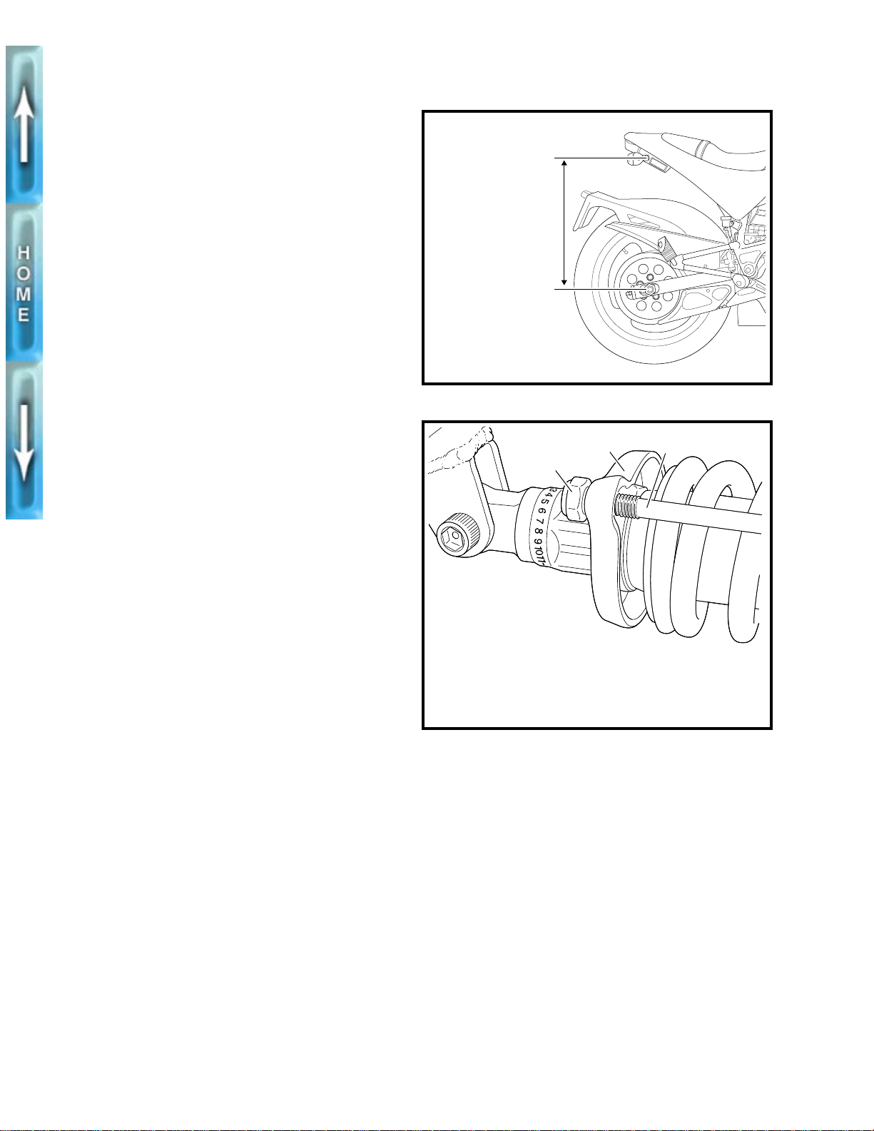
4. See Figure 6. Measure the distance from the center of the
rear axle nut to the rear turn signal mounting bolt
rider/passenger/cargo/accessories on the motorcycle.
5. Install items removed in Step 2. Load all cargo.
6. Bounce a few times on the seat to be sure the suspen-
sion is free and not binding.
7. With the help of an assistant, take the same measure-
ment with the vehicle fully loaded (rider/passenger/luggage/cargo). The assistant should help balance the
motorcycle so the rider can keep both feet on the footrests.
8. Subtract the second measurement from the first. The dif-
ference, which is the squat, should be 0.25-0.75 in. (6.4-
19.1 mm). If it is not, you will have to adjust the spring
preload.
1
CAUTION
Be sure to apply the same number of turns to each
●
preload adjusting nut to ensure that the drawing
rings do not become misaligned. Misaligned drawing
rings will cause the shock absorber spring to bind
against the adjustment rods
Be sure the drawing rings are parallel within 1/64 in.
●
(0.4 mm). Misaligned drawing rings will cause the
shock absorber spring to bind against the adjustment rods.
9. See Figure 7. Change the spring preload by adjusting
both preload adjusting nuts (1) (metric) behind the rear
drawing ring (2).
a. Increase the preload by tightening the nuts.
b. Decrease the preload by loosening the nuts.
without
b0269xox
Rear turn signal
mounting bolt
Rear axle nut
Figure 6. Checking Rear Preload
2 3
1
1. Preload adjusting nut (2) (metric)
2. Rear drawing ring
3. Adjustment rod (2)
Figure 7. Adjusting Rear Preload
b0283x2x
8
Page 9
IGNITION TIMING
MODEL YEAR CHANGE
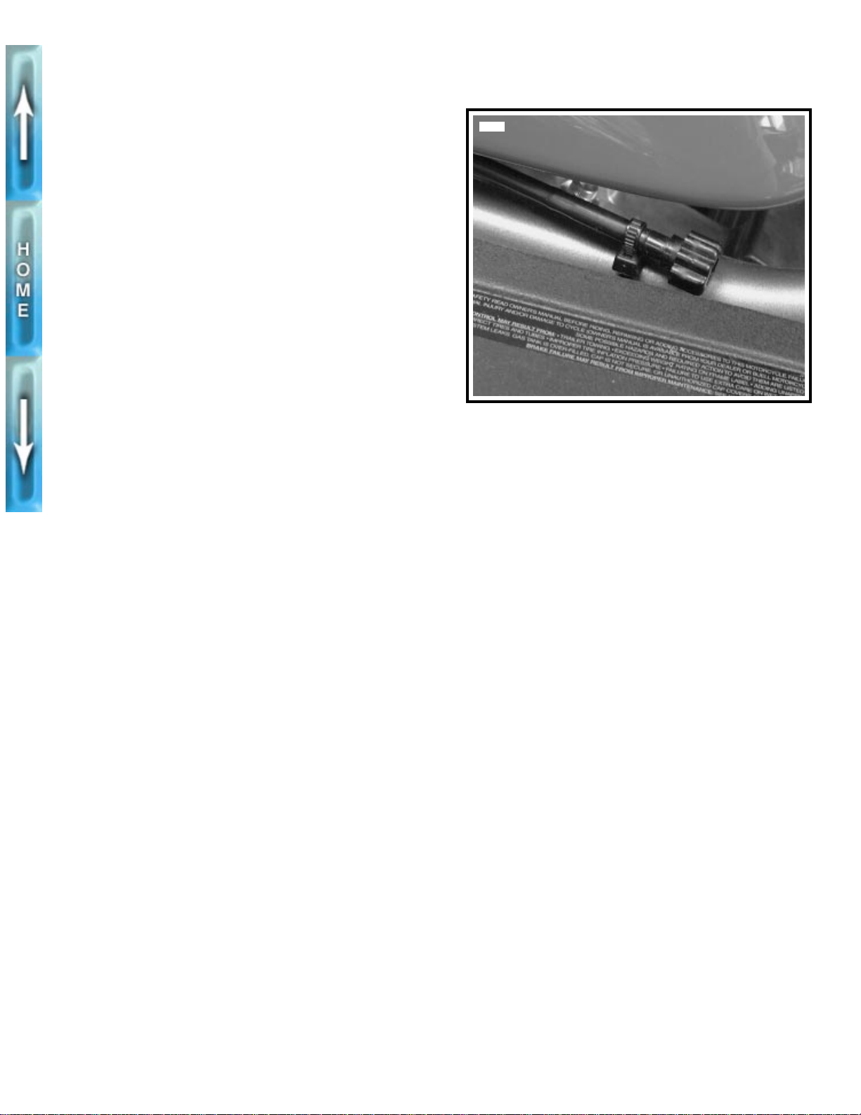
See Figure 8. All 1997 model year motorcycles have the
remote idle adjuster introduced on late 1996 vehicles. Using
this adjuster, it is no longer necessary to use the CARBURE-
TOR IDLE ADJUSTMENT TOOL (Part No. HD-33413) and
TIP (SNAP-ON Part No. TMP23A) to adjust engine idle
speed.
NOTE
The new idle adjuster changes Step 4 of IGNITION TIMING,
INSPECTION in Section 1 the 1996 manual.
See REMOTE IDLE ADJUSTER on page 21 for more infor-
mation.
5853
Figure 8. Remote Idle Adjuster
9
Page 10
NOTES
10
Page 11
SECTION II–CHASSIS
SUBJECT PAGE NO.
1. Vehicle Identification Number . . . . . . . . . . . . . . . . . . . . . . . . . . . . . . . . . . . . . . . . . . . . . . . 13
2. Front Wheel. . . . . . . . . . . . . . . . . . . . . . . . . . . . . . . . . . . . . . . . . . . . . . . . . . . . . . . . . . . . . 14
3. Front Brake Caliper . . . . . . . . . . . . . . . . . . . . . . . . . . . . . . . . . . . . . . . . . . . . . . . . . . . . . . . 15
4. Swingarm . . . . . . . . . . . . . . . . . . . . . . . . . . . . . . . . . . . . . . . . . . . . . . . . . . . . . . . . . . . . . . 16
This section explains procedures unique to 1997 model S1 Lightnings. Any procedures not found
in this supplement are covered in the 1996 S1 Lightning Service Manual (Part No. 99490-96Y).
11
Page 12
NOTES
12
Page 13
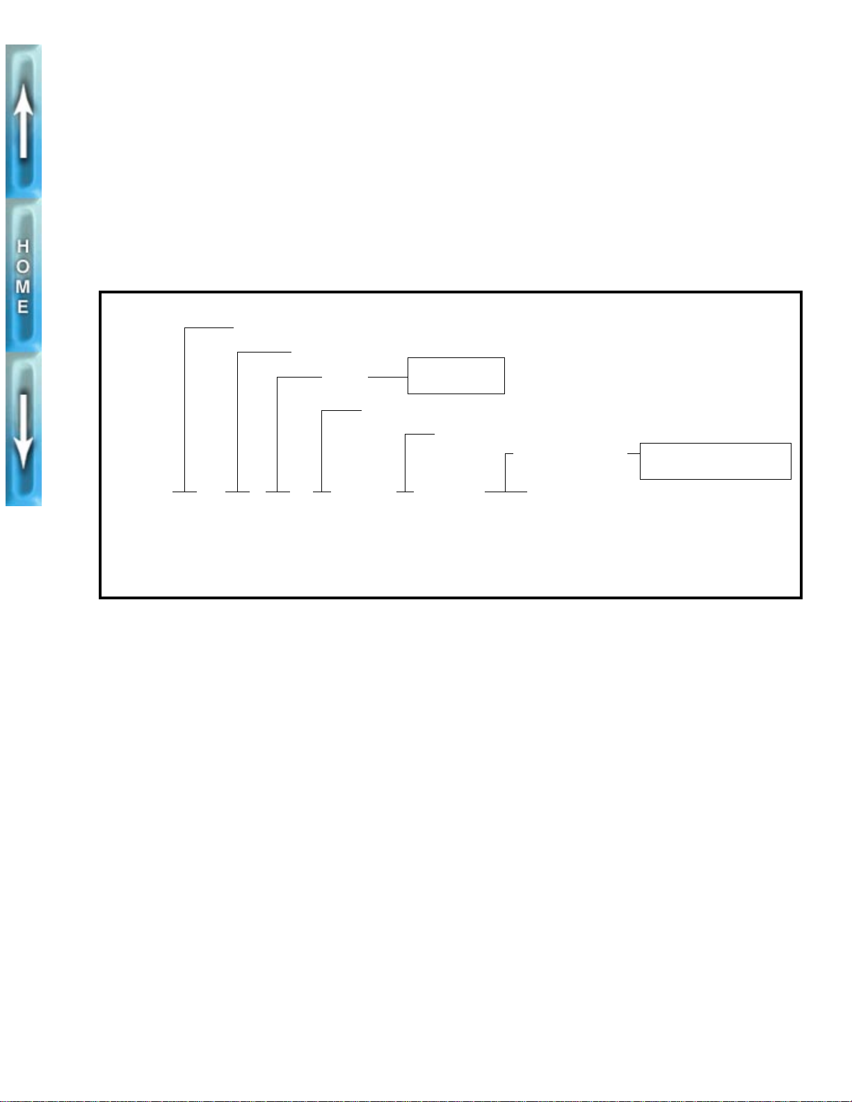
VEHICLE IDENTIFICATION NUMBER
MODEL YEAR CHANGE
See Figure 9. A 17-digit serial number, or Vehicle Identifica-
tion Number (V.I.N.), is stamped on the right side of the steering head (ex., 4MZSS11J1V3200001). Also affixed to the
steering head at this location is an information decal bearing
the V.I.N. code.
Manufacturer: Buell Motorcycle Company
Type Designation
Engine
Horsepower Code
4MZSS 11 J* V 32 00001
Varies - can be 0 thru 9 or X
*
11 = World
56 = California
Model Year - 1997
An abbreviated V.I.N. is stamped on the front left side of the
crankcase.
NOTE
Always give the V.I.N. or abbreviated V.I.N. when ordering
parts or making inquiries about your Buell motorcycle.
Sequential Number
00001-20000 = World
20001-25000 = California
Sample V.I.N. as it appears on the steering head - 4MZSS11J1V3200001
Sample abbreviated V.I.N. as it appears on the left side crankcase- SS11V200001
Figure 9. Vehicle Identification Number (V.I.N.)
13
Page 14
FRONT WHEEL
MODEL YEAR CHANGE
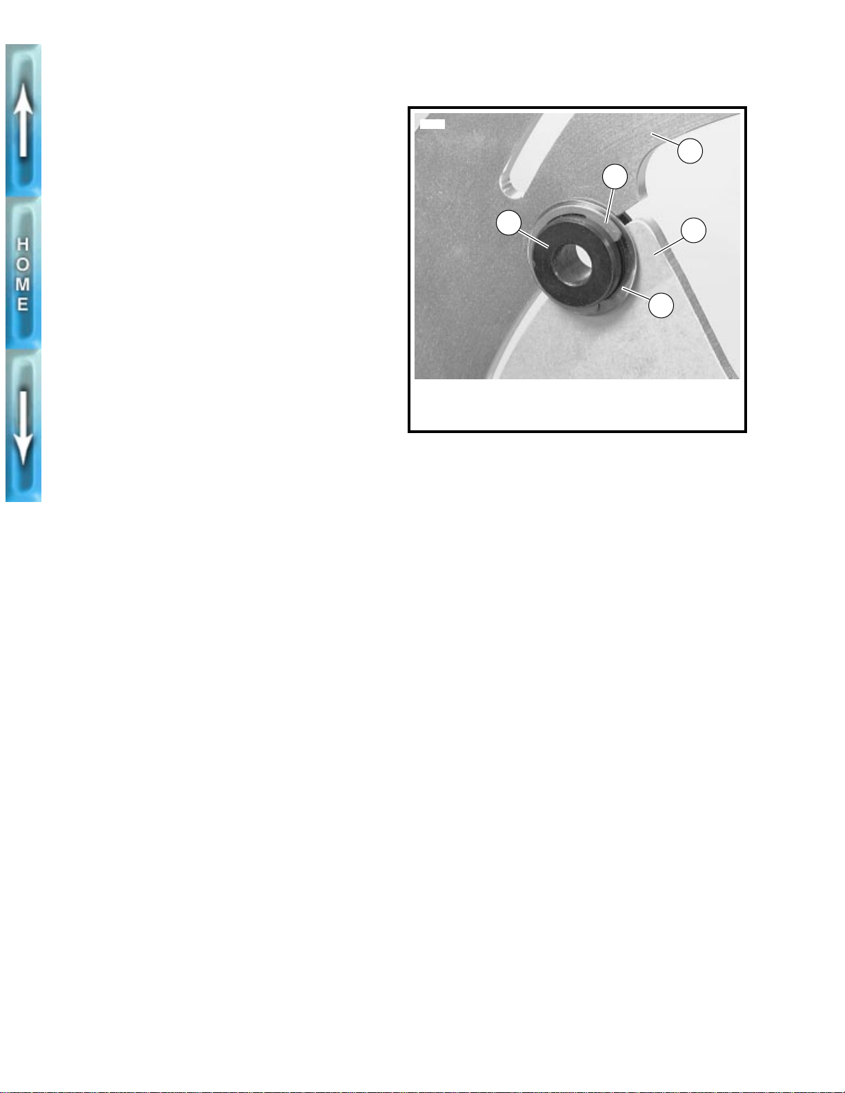
See Figure 10. All 1997 model year motorcycles have new
fasteners on the front brake rotor/carrier assembly.
Separate the carrier from the rotor only when necessary. Use
new
clips when reassembling.
NOTE
The new rotor/carrier assembly changes Step 4 of FRONT
WHEEL, REMOVAL and Step 2 of FRONT WHEEL, ASSEMBLY in the 1996 manual.
REMOVAL/INSTALLATION
1. See Figure 10. Remove and discard the clip (2).
2. Remove the wave washer (3).
3. Remove the drive pin (1). Repeat this procedure for the
other five fasteners to separate the carrier (4) from the
rotor (5).
4. Assemble in reverse order. Use
new
clips upon assembly.
5874
2
1
1. Drive pin (6)
2. Clip (6)
3. Wave washer (6)
Figure 10. 1997 Rotor to Carrier Fastener
4. Carrier
5. Rotor
5
4
3
14
Page 15
FRONT BRAKE CALIPER
TOOL INFORMATION
Use the BRAKE CALIPER PISTON REMOVER (Part No. B-
42079) to simplify front caliper piston removal.
NOTE
The following instructions expand upon Step 9 of FRONT
BRAKE CALIPER, REMOVAL/DISASSEMBLY in the 1996
manual.
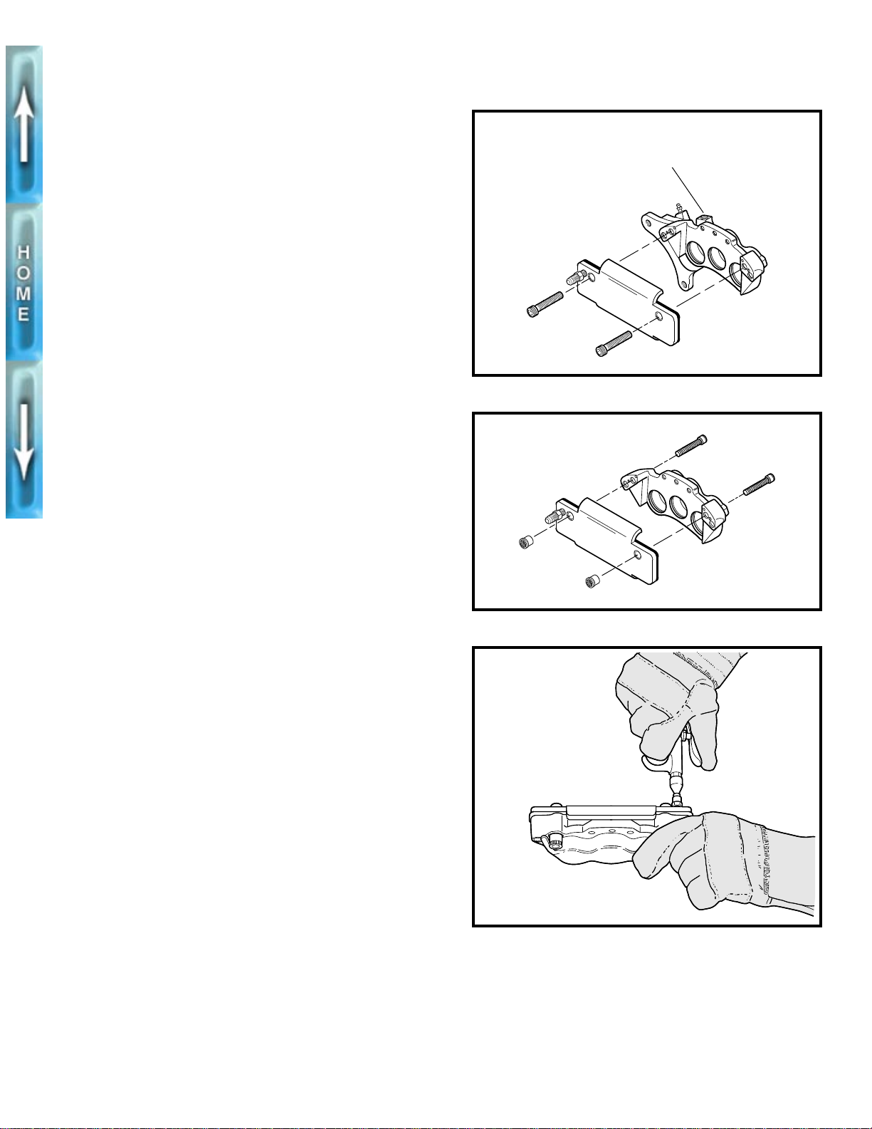
1. Attach caliper half to tool.
a. See Figure 11. Attach outside caliper half using two
screws.
b. See Figure 12. Attach inside caliper half using two
screws and two nuts.
WARNING
1
When using air pressure to remove pistons from caliper,
pistons may be ejected with considerable force. Wear
safety glasses and heavy gloves to prevent personal
injury.
1
CAUTION
Exercise care to avoid dropping piston on hard surface.
Any damage requires piston replacement.
2. If removing pistons from outside caliper half, place a
gloved finger over the banjo bolt hole.
3. See Figure 13. Apply low pressure air to force the pistons
from the caliper bores.
b0265x2x
Banjo bolt hole
Figure 11. Outside Caliper Half
b0266x2x
Figure 12. Inside Caliper Half
b0297x2x
Figure 13. Using Air Pressure to Remove Pistons
15
Page 16
SWINGARM
MODEL YEAR CHANGE
All 1997 model year motorcycles use a revised swingarm
pivot assembly. The modifications allow preload to be
adjusted without using the PIVOT SHAFT BEARING
ADJUSTER (Part No. B-41175).
NOTE
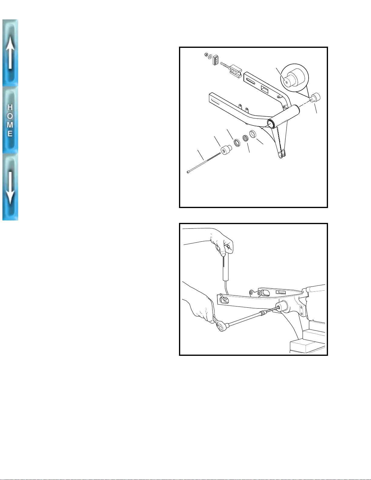
See Figure 14. The threaded rod (1) replaces a pivot shaft
used on 1996 models. This new part changes the SWING-
ARM, ASSEMBLY and SWINGARM, INSTALLATION proce-
dures in the 1996 manual.
ASSEMBLY
1. See Figure 14. If necessary, draw
cups (5) into swingarm using BEARING INSTALLATION
BOLT (Part No. B-35316-5) and STEERING HEAD
BEARING RACE INSTALLER (Part No. HD-39302).
NOTE
Timkin roller bearing assemblies should be replaced as a
unit. Do not intermix components. Mark all components so
they may be correctly installed.
2. Coat bearing components with WHEEL BEARING
GREASE (Part No. HD-99855-89) and assemble.
3. Install a
4. Slide swingarm assembly into position.
See Figure 14. The left side bearing adjustment bolt (6) has
additional internal threads.
5. Install both bearing adjustment bolts (2, 6) and the
threaded rod (1). Insert the rod from the air cleaner side
of the motorcycle.
6. Tighten the left pinch screw on the swingarm mount
block. Do not tighten the right side pinch screw at this
time.
new
swingarm seal (3) flush to the swingarm.
NOTE
new
roller bearing
3
2
1
1. Threaded rod
2. Bearing adjustment
bolt, right
3. Swingarm seal (2)
Figure 14. Swingarm
b0290a2x
Threads
6
5
4
4. Roller bearing (2)
5. Bearing cup (2)
6. Bearing adjustment
bolt, left
b0294x2x
INSTALLATION
1. See Figure 15. Adjust swingarm preload by tightening
the threaded rod. Preload should measure 3.5-5.5 lbs
(1.6-2.5 kg).
2. Follow the remaining installation instructions in the 1996
manual.
16
Figure 15. Adjusting Preload
Page 17
SECTION III–ENGINE
All engine procedures in the 1996 S1 Lightning Service Manual (Part No. 99490-96Y) apply to
1997 models.
17
Page 18
NOTES
18
Page 19
SECTION IV–FUEL SYSTEM
SUBJECT P AGE NO .
1. Remote Idle Adjuster. . . . . . . . . . . . . . . . . . . . . . . . . . . . . . . . . . . . . . . . . . . . . . . . . . . . . . 21
2. Air Cleaner . . . . . . . . . . . . . . . . . . . . . . . . . . . . . . . . . . . . . . . . . . . . . . . . . . . . . . . . . . . . . 22
This section explains procedures unique to 1997 model S1 Lightnings. Any procedures not found
in this supplement are covered in the 1996 S1 Lightning Service Manual (Part No. 99490-96Y).
19
Page 20
NOTES
20
Page 21
REMOTE IDLE ADJUSTER
GENERAL
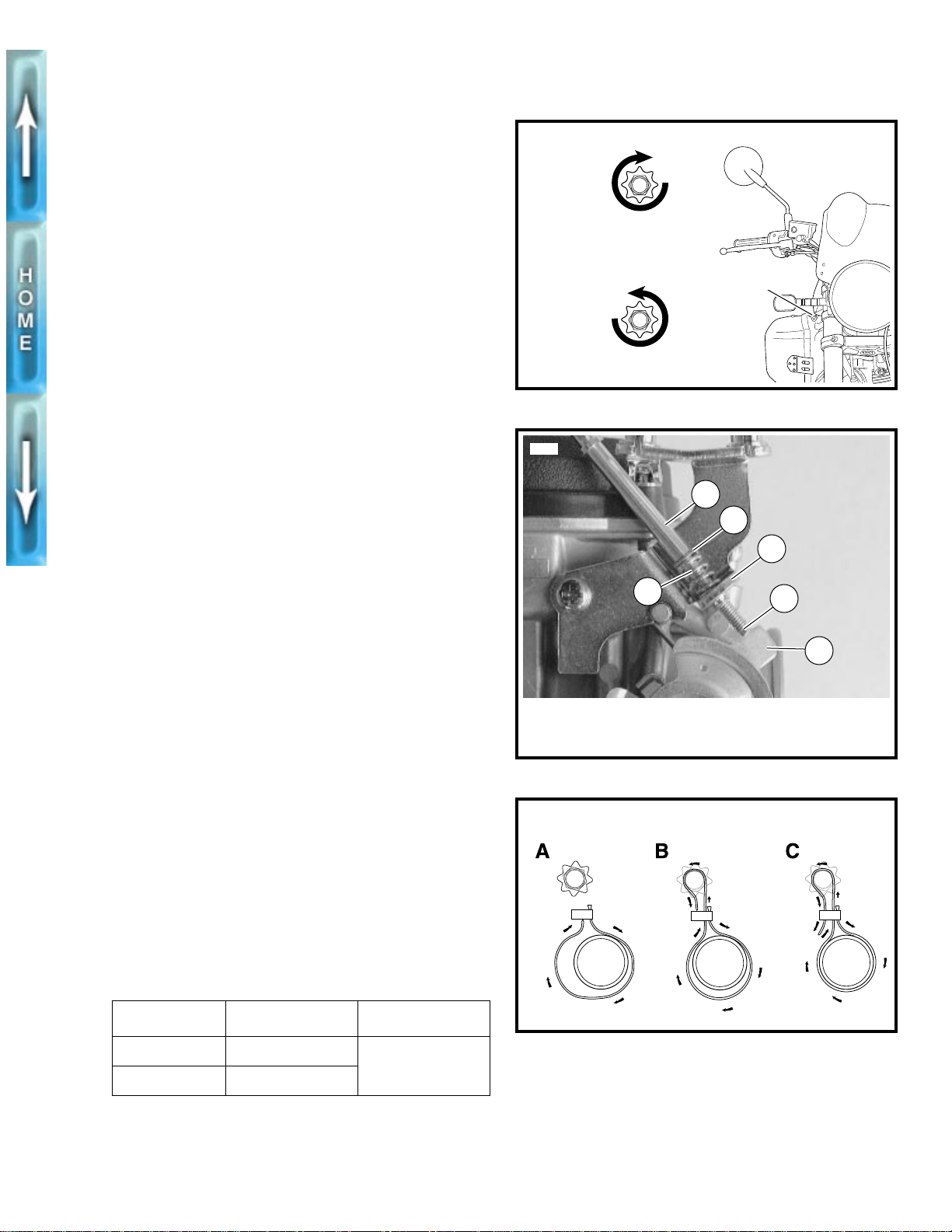
See Figure 16. The remote idle adjuster allows idle adjust-
ments without use of tools. Idle speeds are listed in Table 2.
REMOVAL
1. Remove seat and fuel tank. See FUEL TANK, REMOVAL
in Section 4 of the 1996 manual.
2. Remove cable strap holding adjuster to frame.
3. See Figure 17. Unthread adjuster assembly from bracket
(4). Remove spring (3) and washer (2).
NOTE
If remote idle adjuster is permanently removed, install idle
adjuster screw, spring and two washers. See the 1996 S1
LIGHTNING PARTS CATALOG (Part No. 99571-96Y).
INSTALLATION
1. See Figure 17. Thread remote adjuster (1), spring (3)
and washer (2) into bracket (4). Adjuster shaft (5) must
touch stop plate (6).
2. See Figure 18. Secure adjuster to frame with a figure-8
cable strap.
a. Wrap cable strap around inside of frame, then up
and through the slot.
b. Contine cable strap over adjuster.
c. Run cable strap through the other side of the slot.
Strap should be tight enough that the adjuster turns
easily.
b0291xox
Increase
idle speed
Decrease
idle speed
5900
Adjuster
Figure 16. Idle Speed Adjuster
1
2
4
3
5
6
1
WARNING
After installing seat, pull upward on front of seat to be
sure it is locked in position. If seat is loose, it could shift
during vehicle operation and startle the rider, causing
loss of control and personal injury.
3. Install fuel tank and seat. See FUEL TANK, INSTALLA-
TION in Section 4 of the 1996 manual.
4. Start vehicle and warm engine to normal operating tem-
perature.
5. See Figure 16. Set idle speed by turning adjuster. See
Table 2.
a. Turn clockwise to increase idle speed.
a. Turn counterclockwise to decrease idle speed.
Table 2. Engine Idle Speed
MODEL REGULAR IDLE FAST IDLE
World Model 950-1050 RPM
California 1150-1250 RPM
2000 RPM
1. Remote adjuster
2. Washer
3. Spring
Figure 17. Removal/Installation
b0302x4x
Figure 18. Cable Strap
4. Bracket
5. Shaft
6. Stop plate
21
Page 22
AIR CLEANER
MODEL YEAR CHANGE
All 1997 model year motorcycles use a modified air cleaner
assembly. The new design increases serviceability.
REMOVAL
1
CAUTION
Do not run engine without filter element in place. Debris
could be drawn into the engine causing damage.
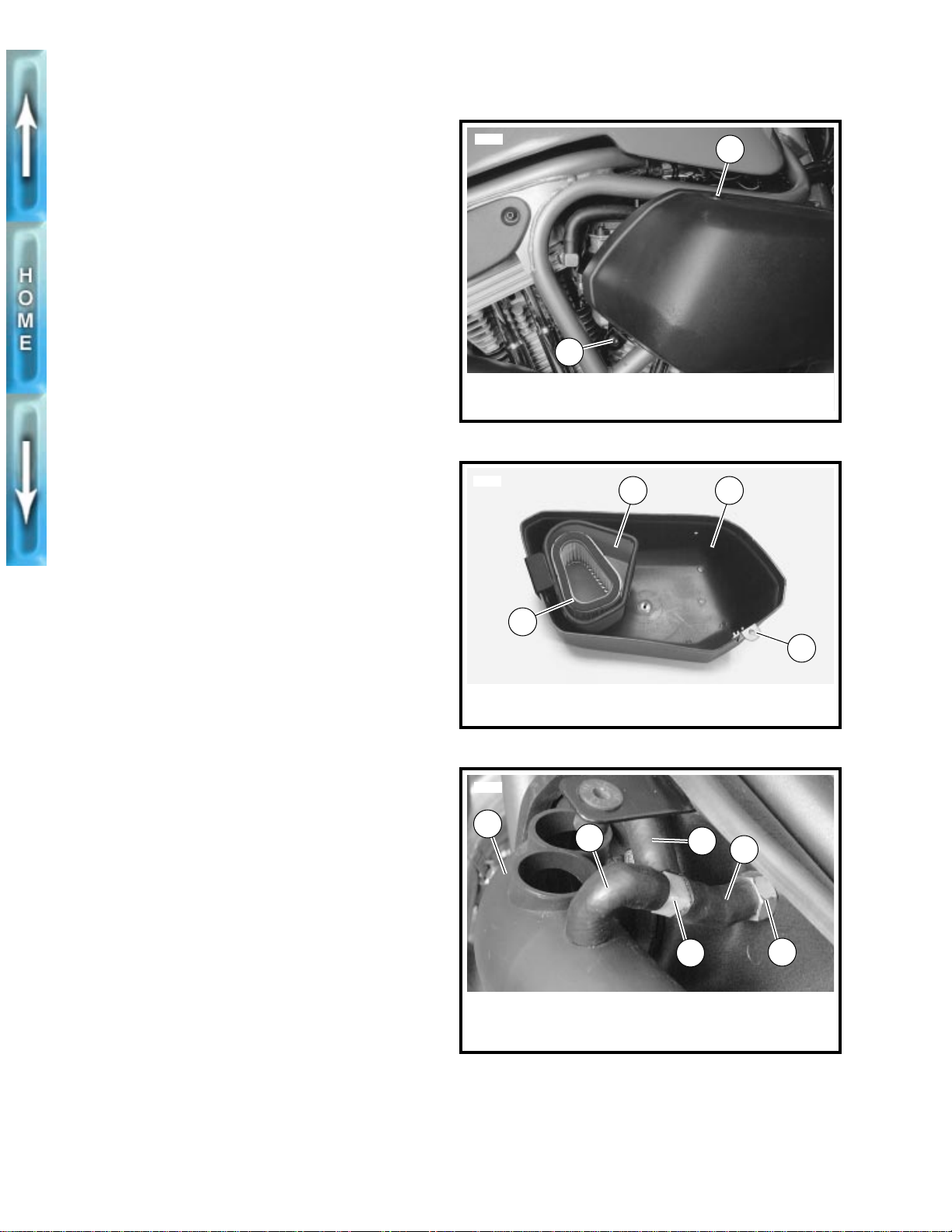
1. See Figure 19. Remove screw and nylon washer (1) on
top of air cleaner cover.
2. Remove screw and lockn ut (2) at rear of air cleaner cov er .
3. See Figure 20. Remove cover (3) with attached filter box
(2) and filter (1).
4. See Figure 21. Remove backplate hoses.
a. Detach rear breather hose (4) from tee fitting (3).
b. Detach snorkel breather hose (2) at snorkel (1).
c. Remove hoses (2, 5) and tee fitting (3) from front
breather bolt (6).
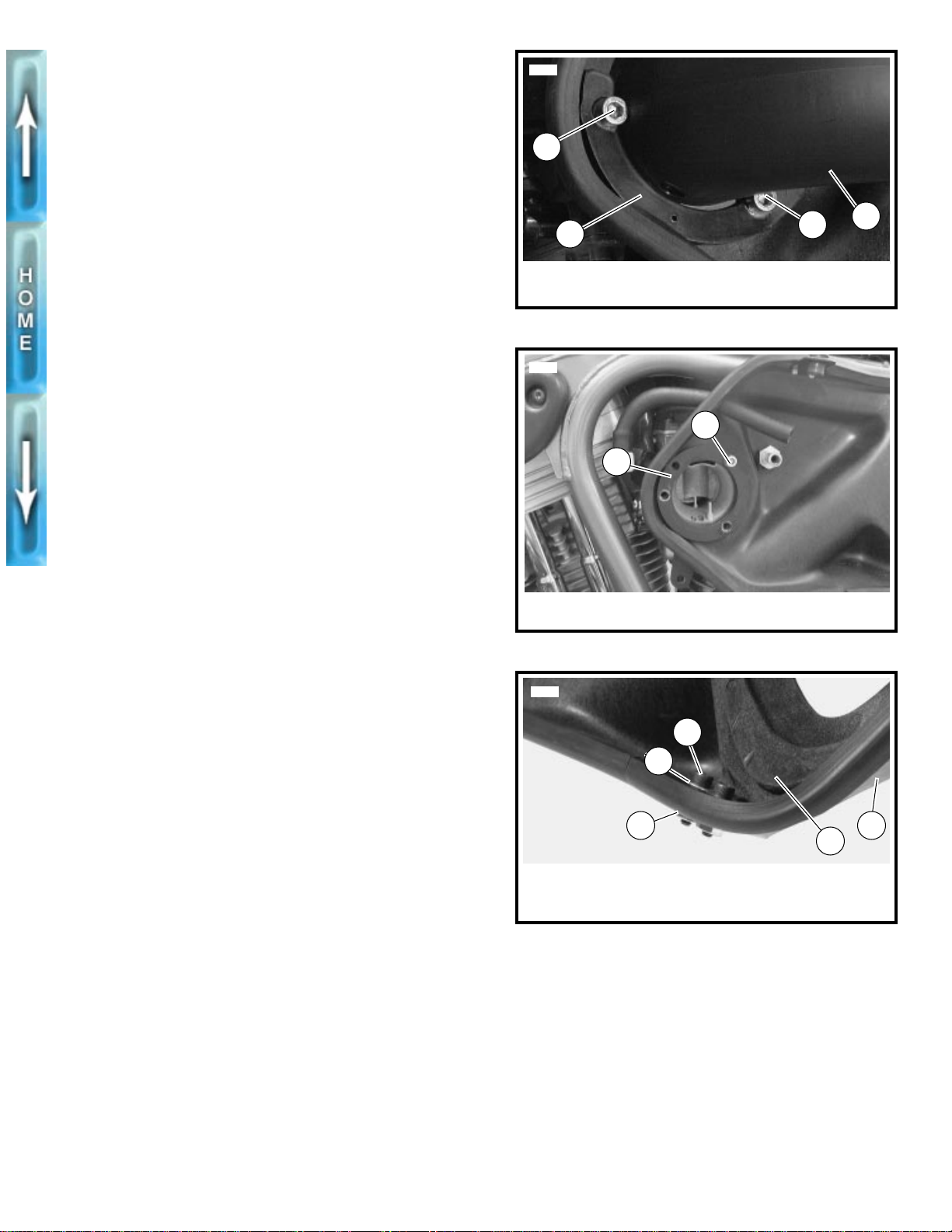
d. On California models, slide fresh air hose from can-
ister through backplate.
5. See Figure 22. Remove two screws and snorkel plate.
6. Remove snorkel.
7. See Figure 23. Remove screw with spacer and gasket.
8. Remove backplate.
a. See Figure 24. Remove two bolts (1), washers (2)
and nuts (3).
b. Draw rear breather hose through backplate.
c. Remove front breather bolt. Detach backplate from
motorcycle.
9. If necessary, remove air cleaner support ring.
a. Detach breather hose from rear cylinder head
breather bolt.
b. Loosen rear bolt.
c. Slide air cleaner support ring upward and remove.
5705
2
1. Screw and nylon washer
2. Screw and locknut
Figure 19. Air Cleaner Cover
5883
2
1
1. Filter
2. Filter box
Figure 20. Inside of Air Cleaner Cover
5881
1
2
1
3
3. Cover
4. Rear mount
4
5
4
NOTE
Air cleaner support ring fits around breather bolts. Fitting on
rear breather bolt may not clear the frame if bolt removal is
attempted. Do not remove rear breather bolt unless absolutely necessary.
22
1. Snorkel
2. Snorkel breather
3. Tee fitting
Figure 21. Breather Hoses
3
4. Rear head breather
5. Front head breather
6. Front breather bolt
6
Page 23
INSTALLATION
1. Install backplate.
a. Apply HYLOMAR to threads of breather bolts.
b. Install air cleaner support ring and backplate using
breather bolts. Tighten breather bolts to 10-15 ft-lbs
(13.6-20.3 Nm).
5884
1
c. Attach rear breather hose to rear breather bolt.
d. See Figure 24. Install two bolts (1), washers (2) and
nuts (3) through backplate into isolator mount.
2. See Figure 21. Install breather hoses.
a. Slide rear breather hose through backplate.
b. Attach front breather hose (5, with attached tee and
snorkel breather hose) to front breather bolt (6).
c. Connect rear breather hose (4) to tee fitting (3).
d. On California models, insert fresh air hose from can-
ister through backplate.
3. See Figure 23. Apply LOCTITE THREADLOCKER 242
(blue) to screw. Install ring with screw through backplate.
Tighten to 7-9 ft-lbs (9.5-12.2 Nm).
4. See Figure 22. Apply LOCTITE THREADLOCKER 242
(blue) to screws. Fasten snorkel tube with ring and two
screws. Tighten to 6-8 ft-lbs (8.1-10.8 Nm).
5. Connect snorkel hose to snorkel tube.
6. See Figure 20. Check air cleaner filter. Place filter inside
filter box. Place cover assembly over backplate.
2
1. Screw (2)
2. Snorkel plate
Figure 22. Snorkel Ring
5897
3. Snorkel
2
1
1. Air cleaner spacer with gasket
2. Screw
Figure 23. Air Cleaner Spacer
1
3
7. See Figure 19. Install screw and washer into top well nut.
8. Install screw and locknut at rear mount. Tighten to 6-8 ftlbs (8.1-10.8 Nm).
5898
1
2
3
1. Bolt (2)
2. Washer (2)
3. Nut (2)
Figure 24. Front Isolator Mount Attachment
4. Backplate
5. Isolator mount
5
4
23
Page 24
NOTES
24
Page 25
SECTION V–ELECTRIC ST ARTER
SUBJECT PAGE NO.
1. Starting System Diagnosis . . . . . . . . . . . . . . . . . . . . . . . . . . . . . . . . . . . . . . . . . . . . . . . . . 27
This section explains procedures unique to 1997 model S1 Lightnings. Any procedures not found
in this supplement are covered in the 1996 S1 Lightning Service Manual (Part No. 99490-96Y).
25
Page 26
NOTES
26
Page 27
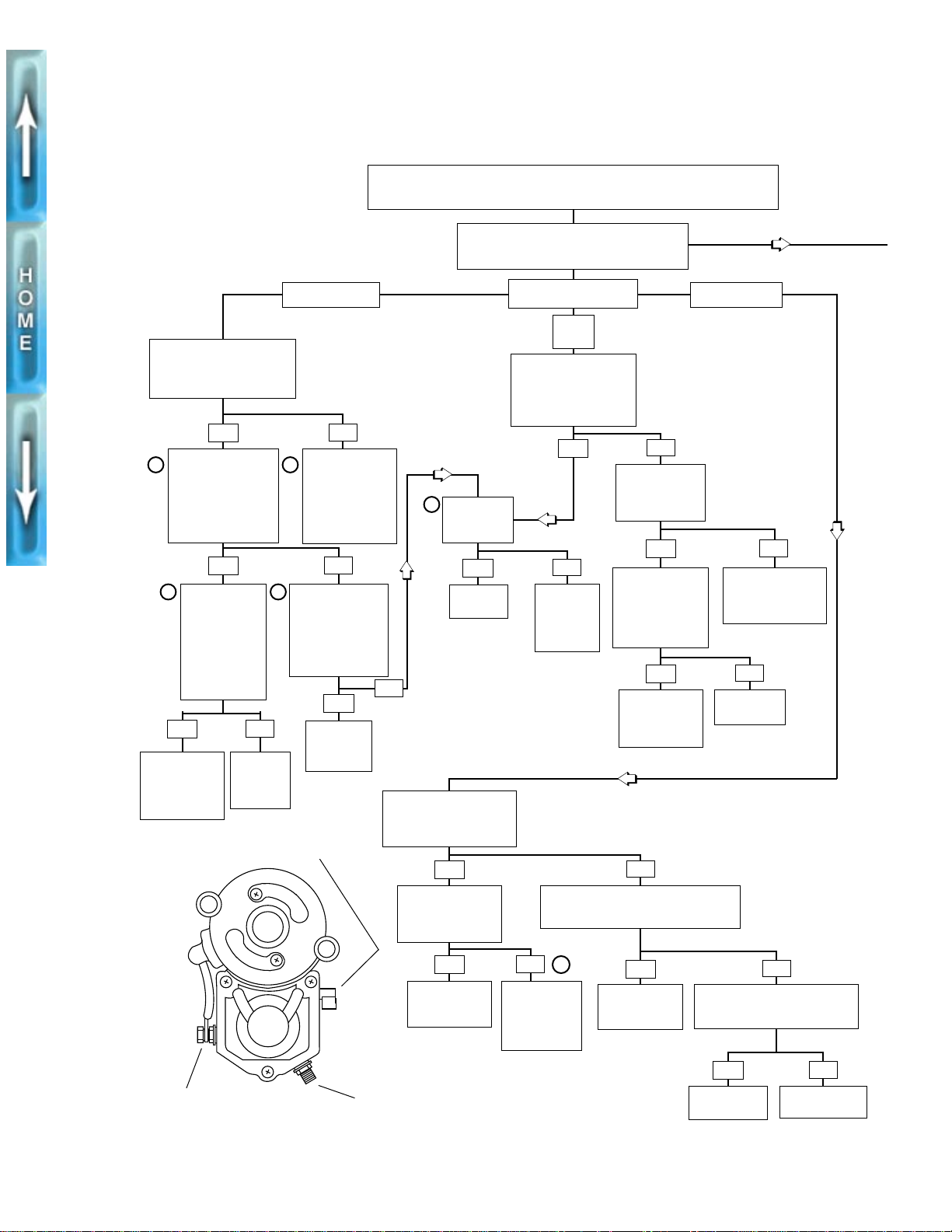
STARTING SYSTEM DIAGNOSIS
Perform V oltage Drop Tests
Between Battery and
“Relay” Terminal on
Solenoid. Less Than 1 Volt?
YES
Perform V oltage Drop
2
Tests from Battery
(Pos. +) to Starter
“Motor”Terminal.
Crank Engine. Is
Voltage Greater than
1 Volt?
YES
2
Perform V oltage
Drop Tests from
Battery (Pos. +)
to Starter Motor
“M” (Battery)
Terminal. Crank
Engine. Is
Volta ge Greater
than 1 Volt?
YES
Repair
Connection
Between
Battery and
Starter.
2
NO
Repair or
Replace
Solenoid
(Contacts).
Relay terminal
Solenoid Clicks.
NO
Backtrack to
2
Pinpoint Poor
Connections or
Relay Contact
Problems Using
Voltage Drop
Tests.
NO
Perform V oltage
Drop Test
Between Battery
(Neg. -) and Starter
Studs or Bolts.
Is Volta ge Greater
than 1 Volt?
YES
Clean
Ground
Connections
● VISUAL ● VOLTAGE ● LOAD
— BATTERY TESTS —
Check Connections at Battery
and Starter Components.
Nothing Clicks.
NO
Starter Relay.
1
Does Starter
Motor Turn if
Jumped?
YES
Replace
Solenoid.
NO
Check for Battery Voltage
at Relay T erminal 86 Fr om
Starter Button. Battery
Voltage Present?
YES
Check for
Ground at Relay
Terminal 85.
Ground Present?
INOPERATIVE
Relay
Clicks.
Test for Voltage at
Solenoid Terminal. Is
12V Present When
Starter Button is
Pressed?
YES
Test for Voltage
to Relay. Is 12V
Present on
Relay Terminal
YES
NO
Test Starter
Motor for
Opens,
Shorts or
Grounds.
Check for Battery Voltage from Starter
Button BK/R Wire. Battery Voltage
Present With Starter Button Pressed?
Test for Voltage
from Relay . Is 12V
Present on Relay
Terminal 87 When
Starter Button is
Pressed?
YES
Repair Open
on GN Wire
Between Relay
and Solenoid.
NO
Continued on
Next Page
NO
Repair Open on
R/BK Wire Feeding
Terminal 30 on
Starter Relay.
NO
Replace
Motor terminal
YES
Substitute
Good Relay
or Test Relay.
Battery terminal
5
NO
Inspect Starter
Interlock
Circuit or
Correct Relay
Ground.
YES
Repair Wiring
From Starter
Button to Relay.
NO
Check for Battery Voltage to
Starter Button W/BK Wire.
Battery Voltage Present?
YES
Replace
Starter Button.
Repair Wiring to
Starter Button.
NO
27
Page 28
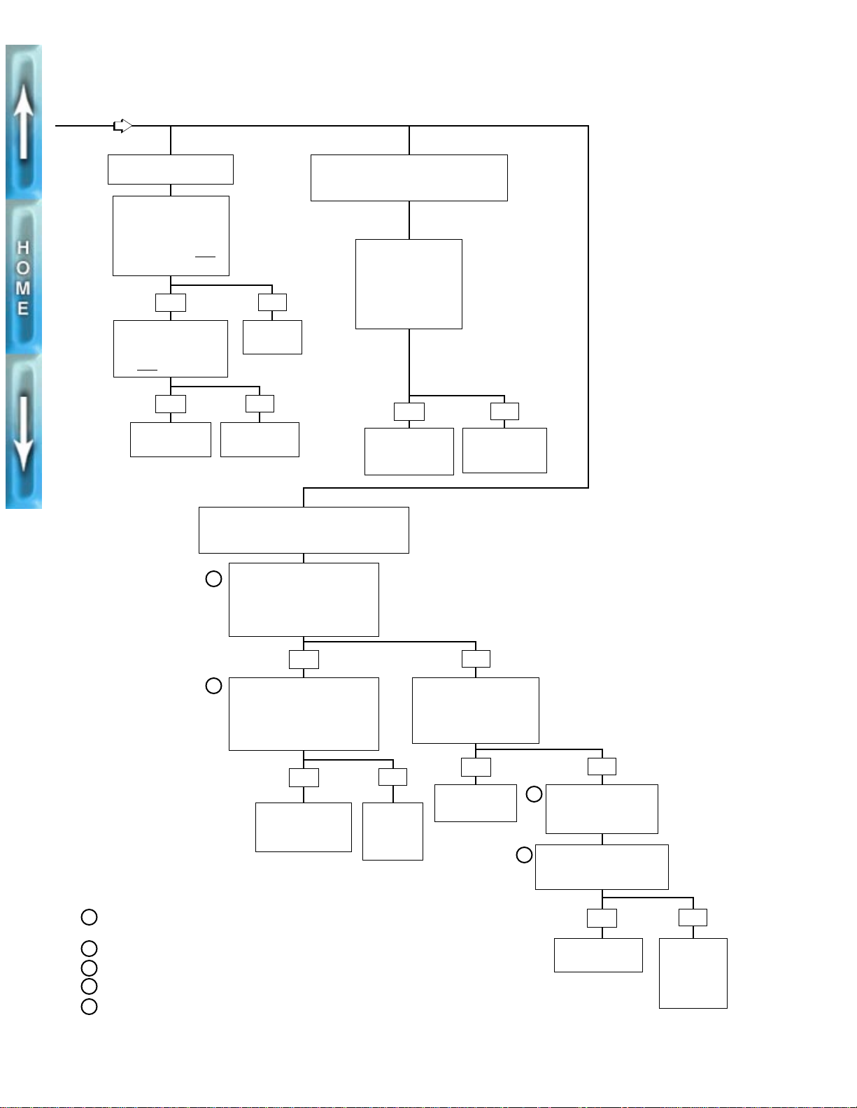
Continued from
Previous Page
RUN-ON
Disconnect Solenoid
“Relay” Terminal from
Solenoid. Is 12V Present
at GN Wire Terminal with
Starter Button NO
Pressed?
YES
Is 12V Present on
Starter Relay Terminal
86 with Starter Button
T Pressed?
NO
YES
Replace Starter
Button.
T
STARTER STALLS OR
STARTER SPINS, BUT
DOES NOT ENGAGE
Remove Starter.
Disassemble Drive
Housing Assembly.
Inspect for Damage
NO
Replace
Solenoid.
NO
Replace Starter
Relay.
to Armature Gear or
Idler Gear. Damage
Damaged Gear
SPINS TOO SLOWLY
Present?
YES
Replace
and Armature.
NO
Starter Clutch
Failure. Replace
Starter Clutch.
2
2
Perform V oltage Drop
Tests from Battery (Pos. +)
to Starter “Motor” Terminal.
Crank Engine. Is V oltage Greater
than 1 Volt?
YES
Perform V oltage Drop
Tests from Battery (Pos. +)
to Starter “Battery” Terminal.
Crank Engine. Is V oltage Greater
than 1 Volt?
YES
Repair Connection
Between Battery
and Starter.
(Contacts).
NOTES
Remove starter motor and connect jumper wires as
1
described in Free Running Current Draw Test.
2
See T roub leshooting/Diagnostics- V oltage drops.
3
See Starter Current Draw Test.
4
See Free Running Current Draw Test.
5
See Starter Interlock Circuit Test
NO
Repair or
Replace
Solenoid
NO
Perform V oltage Drop Test
Between Battery
(Neg. -) and Starter Studs
or Bolts. Is Voltage Greater
than 1 Volt?
YES
Clean Ground
Connections.
4
NO
3
Perform Starter Motor
Current Draw Test (on
Vehicle).
Perform Starter Motor
Free Draw Bench Test. Are
Test Results in Range?
YES
Inspect Engine or
Primary Drive.
NO
Test Starter
Motor
for Opens,
Shorts or
Grounds.
28
Page 29
SECTION VI–DRIVE/TRANSMISSION
All drive/transmission procedures in the 1996 S1 Lightning Service Manual (Part No. 99490-96Y)
apply to 1997 models.
29
Page 30
NOTES
30
Page 31
SECTION VII–ELECTRICAL
SUBJECT PAGE NO.
1. Handlebar Switches . . . . . . . . . . . . . . . . . . . . . . . . . . . . . . . . . . . . . . . . . . . . . . . . . . . . . . 33
2. Starter Interlock System . . . . . . . . . . . . . . . . . . . . . . . . . . . . . . . . . . . . . . . . . . . . . . . . . . . 34
3. Horn . . . . . . . . . . . . . . . . . . . . . . . . . . . . . . . . . . . . . . . . . . . . . . . . . . . . . . . . . . . . . . . . . . 36
4. Wiring Harness . . . . . . . . . . . . . . . . . . . . . . . . . . . . . . . . . . . . . . . . . . . . . . . . . . . . . . . . . . 37
This section explains procedures unique to 1997 model S1 Lightnings. Any procedures not found
in this supplement are covered in the 1996 S1 Lightning Service Manual (Part No. 99490-96Y).
31
Page 32
NOTES
32
Page 33
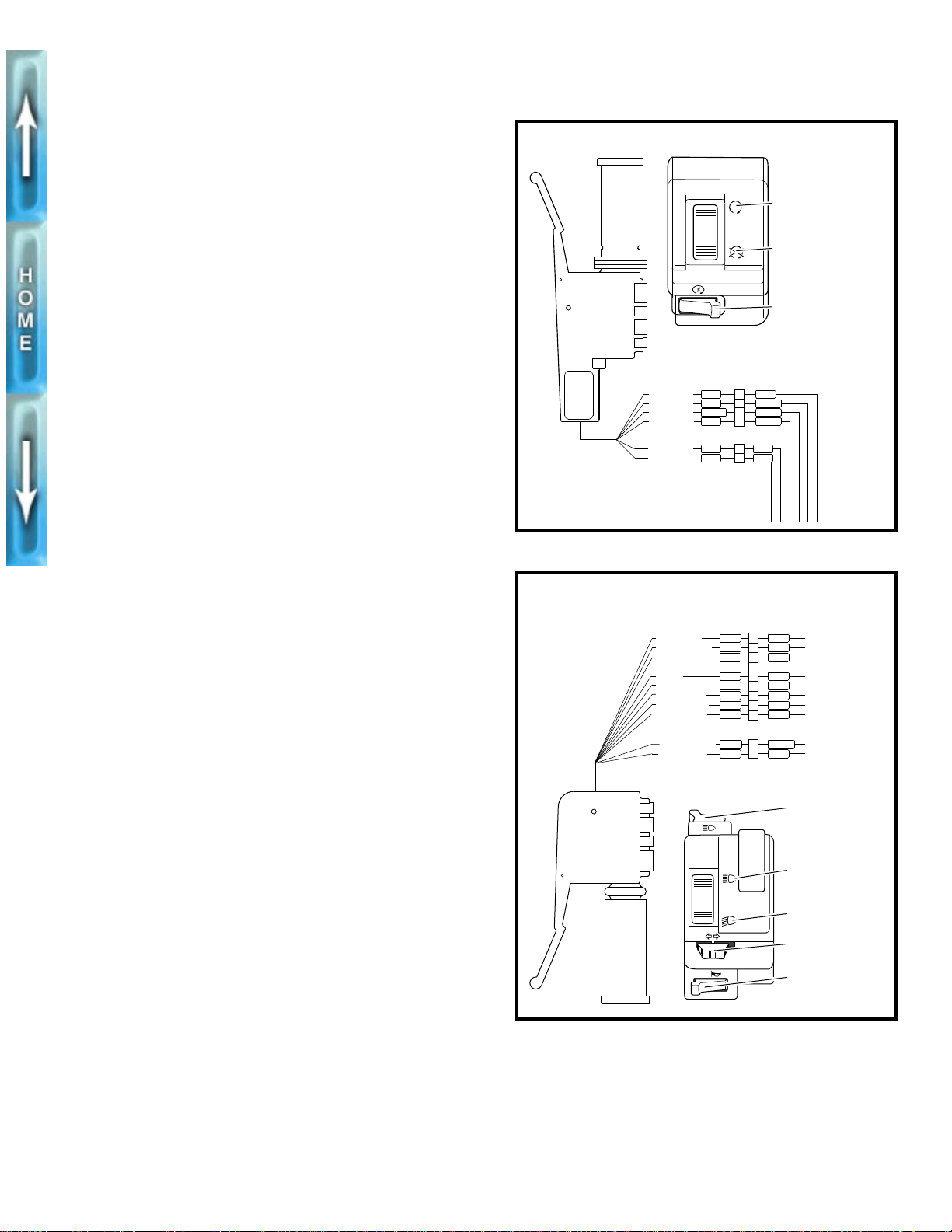
HANDLEBAR SWITCHES
MODEL YEAR CHANGE
All 1997 model year motorcycles use new handlebar
switches. The switches feature new icons, connectors and a
different pin numbering sequence.
NOTE
All HANDLEBAR SWITCHES, REMOVAL and HANDLEBAR
SWITCHES, INSTALLATION procedures remain the same.
The new switch assemblies are interchangeable between
1996 and 1997 models if the corresponding connector on the
wiring harness is changed.
See WIRING HARNESS on page 37 for more information.
Right Handlebar Switch
See Figure 25. The right handlebar switch [P1] contains:
Engine stop switch (ignition ON or OFF)
●
●
Electric starter switch
Left Handlebar Switch
See Figure 26. The left handlebar switch [P6] contains:
●
Passing lamp switch
Headlamp dimmer switch (headlamp HIGH or LOW
●
beam)
●
Turn signal switch
●
Horn switch
b0279x7x
b0274x7x
Ignition ON
Ignition OFF
Electric starter
RIGHT HANDLEBAR
SWITCH CONNECTOR
IGN POWER
IGN MODULE
FROM (2)
TO STARTER
ACC POWER
TO STOPLIGHT
BE
W/R
GN/BK
Y/R
P1
P2
GY
4
W/BK
3
W/BK
2
1
BK/R
O/WO/W
1
R/YR/Y
2
BRAKE SWITCH
Figure 25. Right Handlebar Switch [P1]
LEFT HANDLEBAR
SWITCH CONNECTOR
LT.B E
R/BE
BK
P6
1
2
3
4
5
6
7
8
9
P5
1
2
Y
BE
W
Y/BK
V/BN
V
BN
O/W
TN/GN
BK
W
BN
BK
GN
BE
O
GY
LOW BEAM
LIGHT POWER
HIGH BEAM
HORN
FROM FLASHER
LEFT TURN
RIGHT TURN
HORN POWER
FROM IGN RLY
TO GROUND
CLUTCH SWITCH
Passing lamp
HIGH beam
LOW beam
Turn signals
Horn
Figure 26. Left Handlebar Switch [P6]
33
Page 34
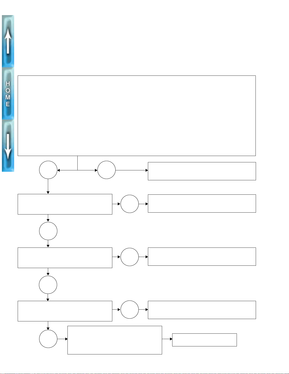
STARTER INTERLOCK SYSTEM
INSPECTION
The starter interlock system is designed to prevent unintended start-up and/or forward motion of the motorcycle with
the vehicle’s side stand not retracted. Use the following two
tests to check the system for proper operation.
The STARTER CIRCUIT and IGNITION CIRCUIT tests
should be performed in one continuous operation. Conduct
both tests one after the other in the sequence given without
interruption
NOTE
Starter Circuit
Raise rear wheel off floor using REAR WHEEL SUPPORT STAND (Part No. B-41174).
Remove GN wire from starter motor.
Connect a test light or voltmeter to the vehicle in series.
a. Attach one end to starter wire terminal.
b. Attach the other end to vehicle ground.
Set engine stop switch to RUN.
Turn ignition switch to IGN.
Place motorcycle in neutral.
Press starter button on right handlebar.
Is current present? (Current is present if test light illuminates or if voltmeter shows 12 VDC ± 1.0 VDC.)
Check neutral switch and circuit. See NEUTRAL INDI-
YES
NO
CATOR SWITCH in Section 7 of the 1996 manual.
Repeat entire interlock circuit test when finished.
Place motorcycle in first gear.
Press starter button on right handlebar.
Is current present?
NO
Disengage clutch lever by pulling lever in fully.
Press starter button on right handlebar.
Is current present?
YES
Release clutch lever.
Press starter button on right handlebar.
Is current present?
Starter circuit operating properly.
No
a. Turn ignition switch to LOCK.
b. Remove test light or voltmeter.
c. Reattach starter motor wire.
YES
NO
YES
Check neutral switch. See NEUTRAL INDICATOR
SWITCH in Section 7 of the 1996 manual. Repeat
entire interlock circuit test when finished.
Check clutch switch. See STARTER INTERLOCK in
Section 7 of the 1996 manual. Repeat entire interlock
circuit test when finished.
Check clutch switch. See STARTER INTERLOCK in
Section 7 of the 1996 manual. Repeat entire interlock
circuit test when finished.
Proceed to IGNITION CIRCUIT
on page 35.
34
Page 35
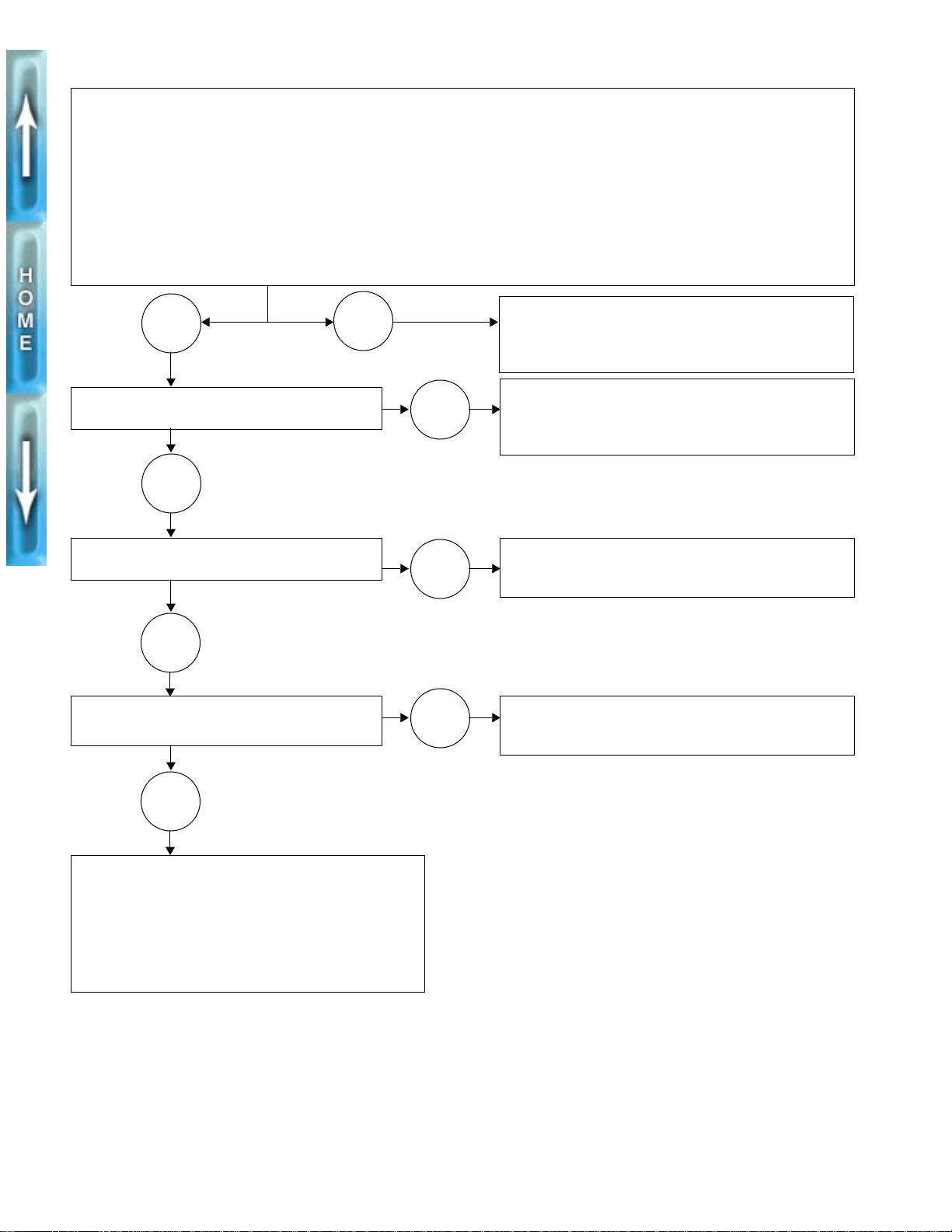
Ignition Circuit
Remove W/BK wire from ignition coil.
Connect a test light or voltmeter to the vehicle.
a. Attach one end to W/BK wire terminal.
b. Attach the other end to vehicle ground.
Turn ignition switch to IGN.
Set engine stop switch to RUN.
Place motorcycle in neutral. Is current present?
YES
Place motorcycle in first gear.
Is current present?
NO
Retract side stand.
Is current present?
YES
Extend side stand.
Pull-in clutch lever. Is current present?
NO
YES
NO
NO
Check neutral switch and circuit. See NEUTRAL INDI-
CATOR SWITCH in Section 7 of the 1996 manual.
Repeat entire ignition portion of interlock circuit test
when finished.
Check neutral switch. See NEUTRAL INDICATOR
SWITCH in Section 7 of the 1996 manual. Repeat
entire ignition portion of interlock circuit test when finished.
Check side stand switch. See STARTER INTERLOCK
in Section 7 of the 1996 manual. Repeat entire ignition
portion of interlock circuit test when finished.
Check clutch switch. See STARTER INTERLOCK in
Section 7 of the 1996 manual. Repeat entire ignition
portion of interlock circuit test when finished.
YES
Ignition circuit operating properly.
a. Turn ignition switch to LOCK.
a. Set engine stop switch to OFF.
b. Remove test light or voltmeter.
c. Reconnect W/BK wire to ignition coil.
d. Remove REAR WHEEL SUPPORT STAND.
35
Page 36
HORN
MODEL YEAR CHANGE
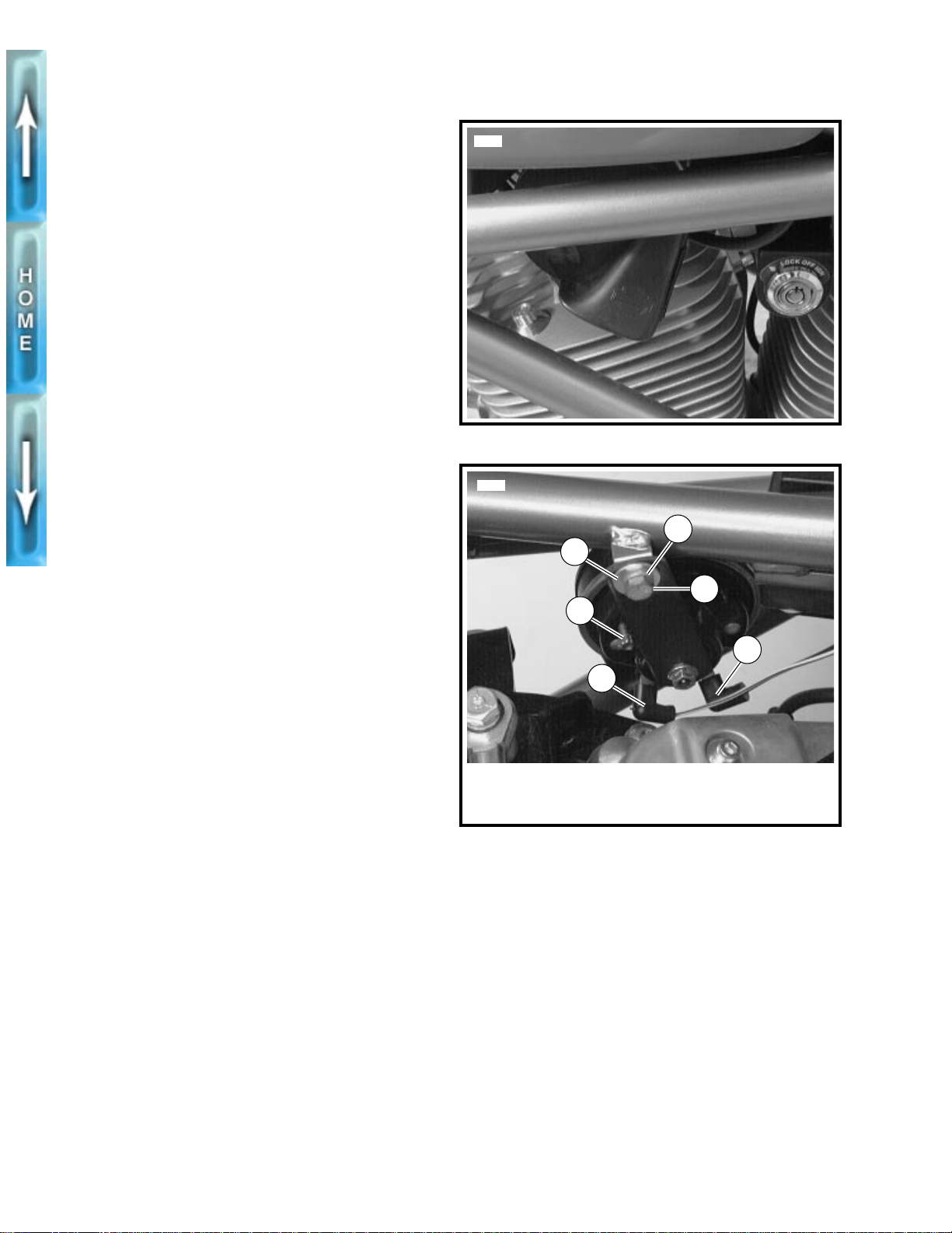
See Figure 27. All 1997 model year motorcycles have a new
horn in a new location.
NOTE
For troubleshooting information, see HORN, TROUBLE-
SHOOTING in Section 7 in the 1996 manual.
REMOVAL
1. Remove seat and fuel tank. See FUEL T ANK, REMOVAL
in Section 4 of the 1996 manual.
2. See Figure 28. Detach horn wires.
a. Disconnect Y/BK power wire (5).
b. Disconnect BK ground wire (6).
3. Remove bolt (1), lockwasher (2) and washer (3) to
detach horn and bracket from frame.
INSTALLATION
1. See Figure 28. Attach horn assembly to frame using
bolt (1), lockwasher (2) and washer (3).
2. Connect horn wires.
a. Attach Y/BK power wire (5).
b. Attach BK ground wire (6).
5882
Figure 27. Horn Location
5875
2
3
1
4
1
WARNING
After installing seat, pull upward on front of seat to be
sure it is locked in position. If seat is loose, it could shift
during vehicle operation and startle the rider, causing
loss of control and personal injury.
3. Install fuel tank and seat. See FUEL TANK, INSTALLA-
TION in Section 4 of the 1996 manual.
1. Bolt
2. Lockwasher
3. Washer
Figure 28. Horn Attachment
6
5
4. Adjuster
5. Power wire (Y/BK)
6. Ground wire (BK)
36
Page 37
WIRING HARNESS
MODEL YEAR CHANGE
The following changes were made to the wiring harness for
1997 model year motorcycles.
●
New connectors and a different pin numbering sequence
for the right handlebar switch [P1] and the left handlebar
switch [P6]. See HANDLEBAR SWITCHES on page 33.
●
Longer wires leading to the horn to accommodate the
new mounting position.
Table 3. Electrical Connectors
CONNECTOR
NUMBER
[P1] 4-place connector right handlebar switch housing-ignition power, module and starter
[P2] 2-place Amp Multilock front brake switch
[P3] 12-place Amp Multilock instruments and indicator lamps
[P4] 4-place Amp Multilock headlamp
[P5] 2-place Amp Multilock clutch switch
[P6] 8-place connector left handlebar switch housing-horn, turn signals, lights
[P7] 2-place Deutsch vacuum-operated electric switch
[P8] 4-place PED ignition/headlamp switch
[P9] 4-slot fuse block four 15 amp fuses-ignition, instruments, lights and accessories
[P10] 8-place Deutsch ignition module
[P11] 8-place Amp Multilock tail lamp and rear turn signals
[P12] 4-place relay ignition relay
[P13] 4-place relay starter relay
[P14] 2-place Amp Multilock side stand switch
DESCRIPTION COMPONENT(S)
[P15] 2-place Amp Multilock license plate light
[P16] 3-place Deutsch timer and pickup
[P17] 2-place plug voltage regulator
37
Page 38
38
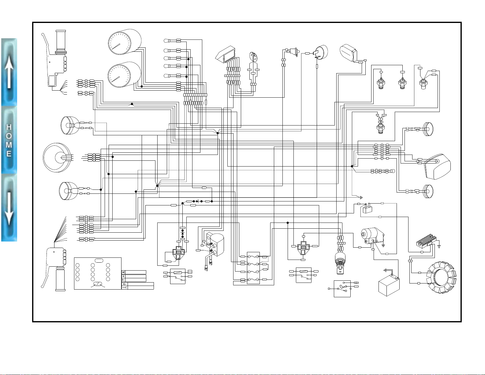
1997 BUELL WIRING DIAGRAM
S2
6/10/96
S7
LEFT TURN
RIGHT
TURN
HIGH BEAM
OIL
PRESSURE
SPEEDOMETER
TACHOMETER
NEUTRAL
W
GN/Y
O
BK
V
BK
O
W/GN
BK
PK
BK
BN
O/W
O
TN
123456789101112
O
O
BK
BK
VBNW
GN/Y
PK
TN
P10
P3
O/W
ELECTRONIC IGNITION
TIMER AND PICKUP
BK
PK
BK/W
GN/W
W/BK
R/W
V/W
12345678
BK
PK
BK/W
GN/W
W/BK
R/W
V/W
P16
/WGN
/WBK
CB
A
R/W
P7
BK
BK
21
KB
/WV
FLASHER
VACUUM SWITCH
O/W
V/BN
HORN
BK
/BYK
GN/Y
TN
OIL PRESSURE
SWITCH
NEUTRAL
SWITCH
R/Y
R/Y
O/W
REAR
STOPLIGHT
SWITCH
TN/WBK
BK W
P14
12
SIDE STAND
SWITCH
RIGHT REAR
TURN SIGNAL
1
2
3
4
5
6
7
8
P11
BK
BK
BK
V
R/Y
BN
V
O/W
BK
BK
R/Y
V
BK
BK
1
2
1
2
P15
BE BE Y
BK BK BK
LICENSE PLATE
LIGHT
MAIN CHASSIS GROUND
R/Y
BK
O/W
BE
R/BK
TAIL LAMP
LEFT REAR
TURN SIGNAL
BEBK
LT.BE
30A
MASTER
CIRCUIT
BREAKER
R
ABC
D
P8
P17
/RGY
/RGY
/BRK
R
/BR
R
K
BK
BK
BK
GN
VOLTAGE REGULATOR
BK
BK
BK
BK
STATOR
BATTERY
R
/BRK
/RGY
KEY SWITCH
LOCK
OFF
IGN
85
30
BK/R
R/BK
86
87
87A
GN
TN/GN
STARTER RELAY
P13
BK/R
GN
R/BK
TN/GN
VIEW FROM FUSE
INSERTION SIDE
GY/O
BE
O/W
O/W
O
O
R/BK
R/BK
R/BK
R/GY
INSTRUMENTS
15A
LIGHTS
15A
15A
ACCESSORIES
15A
IGNITION
FUSE BLOCK
P9
REAR PLUG
FRONT PLUG
COIL
PK
PK
W/BK
85
30
86
87
87A
GY/O
GY/O
TN/W
TN/W
GY
IGNITION RELAY
GY/O
GY/O
P12
S14
S15
TN/W
TN/W
TN/GN
GY
BK
1
2
BK
TN/GN
R/BE
P6
P5
CLUTCH SWITCH
LOW BEAM
HIGH BEAM
HORN
LIGHT POWER
LEFT TURN
FROM FLASHER
HORN POWER
RIGHT TURN
TO GROUND
FROM IGN RLY
1
3
4
5
6
7
8
9
2
BE
Y
O/W
BN
V/BK
Y/BK
W
W
BN
BK
GN
BE
O
LT.BE
GY
V
TN
TN/GN
TN/GN
TN/GN
S11
S10
S12S13
TN
S3
S1
S5
BKBE
VLT.BE
S9
S4
P4
W
BK
Y
2
3
4
O/W
1
BK
W
O/W
Y
POSITION LMP
HIGH BEAM
LOW BEAM
LMP GROUND
HEADLAMP
LEFT FRONT
TURN SIGNAL
RIGHT FRONT
TURN SIGNAL
BNR/BK
KBBE
S8
GY
W/BK
W/BK
BK/R
1
3
2
4
GN/BK
W/R
BE
Y/R
P1
P2
BRAKE SWITCH
1
2
O/W
O/W
R/Y
R/Y
TO STOPLIGHT
ACC POWER
IGN MODULE
FROM (2)
TO STARTER
IGN POWER
S6
BN
O/W
BN
LT.BE LIGHT BLUE
CABLE COLOR
BE
COLOR CODE:
BK
BN
GN
GY
O
BLUE
BLACK
BROWN
GREEN
GRAY
ORANGE
PINK
RED
TAN
VIOLET
WHITE
YELLOW
PK
R
TN
V
W
Y
STRIPE COLOR
XX XX
PIN CONNECTOR
SOCKET CONNECTOR
NO CONNECTION
CONNECTION
DIODE
b0245a7x
Figure 29. 1997 Wiring Diagram
Page 39
FOREWORD
GENERAL
This Service Manual Supplement has been prepared with two
purposes in mind. First, it will acquaint the user with the
construction of the 1997 Buell S1 Lightning and assist in the
performance of basic maintenance and repair. Secondly, it
will introduce to the professional Buell Technician the latest
field-tested and factory-approved major repair methods. We
sincerely believe that this Service Manual Supplement will
make your association with Buell products more pleasant and
profitable.
HOW TO USE YOUR SERVICE MANUAL SUPPLEMENT
1. Check the TABLE OF CONTENTS following this
FORWORD to find the desired subject.
2. If the information you seek is not in this supplement, refer
to the corresponding section in the Buell 1996
S1 Lightning Service Manual (Part No. 99490-96Y).
Check the TABLE OF CONTENTS or INDEX to find the
desired subject.
3. Information is presented in a definite order as follows:
PREPARATION FOR SERVICE
1
WARNING
Gasoline is extremely flammable and highly explosive.
Always stop the engine when refueling or servicing the
fuel system. Do not smoke or allow open flame or sparks
near the work site. Inadequate safety precautions may
result in personal injury.
Good preparation is very important for efficient service work.
A clean work area at the start of each job will allow you to
perform the repair as easily and quickly as possible, and will
reduce the incidence of misplaced tools and parts. A
motorcycle that is excessively dirty should be cleaned before
work starts. Cleaning will occasionally uncover sources of
trouble. Tools, instruments and any parts needed for the job
should be gathered before work is started. Interrupting a job
to locate tools or parts is an unnecessary distraction and
causes needless delay.
SERVICE BULLETINS
In addition to the information presented in this Service
Supplement, Buell Distribution Corporation will periodically
issue Service Bulletins to Buell dealers. Service Bulletins
cover interim engineering changes and supplementary
information.
Specifications
General/Model Y ear Change
Adjustment/T esting
Removal/Disassembly
Cleaning, Inspection, and Repair
Assembly/Installation
In figure legends, the number which follows the name of a
part indicates the quantity necessary for one complete
assembly.
NOTE
To avoid needless disassembly, carefully read all relative
service information before repair work is started.
USE GENUINE REPLACEMENT PARTS
1
WARNING
When replacement parts are required, use only genuine
Buell parts or parts with equivalent characteristics
(which include type, strength and material). Failure to do
so may result in product malfunction and possible injury
to the operator and/or passenger.
To ensure satisfactory and lasting repairs, carefully follow the
instructions and use only genuine Buell replacement parts.
This is your assurance that the parts you are using will fit
right, operate properly and last longer.
i.
Page 40
PRODUCT REFERENCES
1
WARNING
Follow the directions listed on all products. Carefully
read all labels, warnings and cautions before use.
Inadequate safety precautions may result in personal
injury.
When reference is made in this Service Manual Supplement
to a specific brand name product, tool or instrument, an
equivalent product, tool or instrument may be substituted.
Kent-Moore Products
All tools mentioned in this supplement with an “HD”, “J” or “B”
preface must be ordered through:
Kent-Moore
SPX Corporation
29784 Little Mack
Roseville, Michigan 48066-2298
Telephone: 1-800-345-2233
Sealing and Threadlocking Products
LOCTITE PRODUCTS
Some procedures call for the use of Loctite® products. If you
have any questions regarding Loctite product usage or
retailer/wholesaler locations, please call Loctite Corp. at 1800-323-5106.
CONTENTS
All photographs and illustrations may not necessarily depict
the most current model or component, but are based on the
latest production information available at the time of
publication.
Since product improvement is our continual goal, Buell
reserves the right to change specifications, equipment or
designs at any time without notice and without incurring
obligation.
WARNINGS AND CAUTIONS
Statements in this supplement preceded by the word
“1WARNING” or “1CAUTION”
these items alert you to situations where the possibility of
personal injury or vehicle damage exists, please take special
notice of them.
1
WARNING
A “WARNING” indicates the potential for personal injury,
whether to yourself or others.
CAUTION
1
A “CAUTION” indicates that vehicle damage can occur.
1
WARNING
●
Proper service and repair is important for the safe,
reliable operation of all mechanical products. The
service procedures recommended and described in
this Service Manual are effective methods for
performing service operations. Some of these
service operations require the use of tools specially
designed for the purpose. These special tools should
be used when and as recommended. It is important
to note that some warnings against the use of
specific service methods, which could damage the
motorcycle or render it unsafe, are stated in this
Service Manual. However, please remember that
these warnings are not all-inclusive.
●
Since Buell could not possibly know, evaluate or
advise the service trade of all possible ways in which
service might be performed, or of the possible
hazardous consequences of each method, we have
not undertaken any such broad evaluation.
Accordingly, anyone who uses a service procedure
or tool which is not recommended by Buell must first
thoroughly satisfy himself that neither his nor the
operator’s safety will be jeopardized as a result.
●
Wear eye protection when using hammers, arbor or
hydraulic presses, gear pullers, spring compressors,
slide hammers and similar tools. Be especially
cautious when using pulling, pressing or
compressing equipment. The forces involved can
cause parts to fly outward with considerable force,
possibly resulting in personal injury.
are very important. Since
Buell products are manufactured under one or more of the following patents: U.S. Patents – 2986161, 2987934,
2998809, 3116089, 3144531, 3144860, 3226994, 3229792, 3434887, 3559773, 3673359, 3709317, Des. 225 626.
ii.
Page 41
1
GENERAL
SERVICING A NEW MOTORCYCLE
1
WARNING
Always follow the listed service and maintenance
recommendations, since they affect the safe operation of
the motorcycle and the personal welfare of the rider.
Failure to follow recommendations may cause personal
injury.
Service operations to be performed before customer delivery
are specified in the applicable model year PREDELIVERY
AND SETUP MANUAL.
The performance of new motorcycle initial service is required
to keep warranty in force and to ensure proper emissions
systems operation.
After a new motorcycle has been driven its first 500 miles,
and again at 2500 mile intervals, a Buell dealer should
perform the service operations listed in the REGULAR
MAINTENANCE INTERVALS chart on page 1-9.
SAFE OPERATING MAINTENANCE
A careful check of certain equipment is necessary after
periods of storage, and frequently between regular service
intervals, to determine if additional maintenance is required.
1
CAUTION
●
Do not attempt to retighten engine head bolts.
Retightening can cause engine damage.
●
During the initial 500 mile (800 km) break-in period,
use only 20W50 engine oil. Failure to use the
recommended oil will result in improper break-in of
the engine cylinders and piston rings.
Do not lubricate the enrichment cable on C.V.
●
carburetors. The cable requires friction to operate
properly.
SHOP PRACTICES
Repair Notes
NOTE
●
General maintenance practices are given in this section.
●
Repair = Disassembly/Assembly.
●
Replace = Removal/Installation.
All special tools and torque values are noted at the point of
use.
All required parts or materials can be found in the appropriate
PARTS CATALOG.
Safety
Safety is always the most important consideration when
performing any job. Be sure you have a complete
understanding of the task to be performed. Use common
sense. Use the proper tools. Protect yourself and bystanders
with approved eye protection. Don’t just do the job – do the
job safely.
Removing Parts
Always consider the weight of a part when lifting. Use a hoist
whenever necessary. Do not lift heavy parts by hand. A hoist
and adjustable lifting beam or sling are needed to remove
some parts. The lengths of chains or cables from the hoist to
the part should be equal and parallel and should be
positioned directly over the center of the part. Be sure that no
obstructions will interfere with the lifting operation. Never
leave a part suspended in mid-air.
Always use blocking or proper stands to support the part that
has been hoisted. If a part cannot be removed, verify that all
bolts and attaching hardware have been removed. Check to
see if any parts are in the way of the part being removed.
When removing hoses, wiring or tubes, always tag each par t
to ensure proper installation.
Check:
1. Tires for abrasions, cuts and correct pressure.
2. Secondary drive belt for proper tension and condition.
3. Brakes, steering and throttle for responsiveness.
4. Brake fluid level and condition. Hydraulic lines and
fittings for leaks. Also, check brake pads and rotors for
wear.
5. Cables for fraying, crimping and free operation.
6. Engine oil and transmission fluid levels.
7. Headlamp, passing lamp, tail lamp, brake lamp and turn
signal operation.
Cleaning
If you intend to reuse parts, follow good shop practice and
thoroughly clean the parts before assembly. Keep all dirt out
of parts; the unit will perform better and last longer. Seals,
filters and covers are used in this vehicle to keep out
environmental dirt and dust. These items must be kept in
good condition to ensure satisfactory operation.
Clean and inspect all parts as they are removed. Be sure all
holes and passages are clean and open. After cleaning,
cover all parts with clean lint-free cloth, paper or other
material. Be sure the part is clean when it is installed.
Always clean around lines or cov ers before they are removed.
Plug, tape or cap holes and openings to keep out dirt, dust
and debris.
1-1
Page 42
Disassembly and Assembly
Bushings
Always assemble or disassemble one part at a time. Do not
work on two assemblies simultaneously. Be sure to make all
necessary adjustments. Recheck your work when finished.
Be sure that everything is done.
Operate the vehicle to perform any final check or
adjustments. If all is correct, the vehicle is ready to go back to
the customer.
REPAIR AND REPLACEMENT PROCEDURES
Hardware and Threaded Parts
Install helical thread inserts when inside threads in castings
are stripped, damaged or not capable of withstanding
specified torque.
Replace bolts, nuts, studs, washers, spacers and small
common hardware if missing or in any way damaged. Clean
up or repair minor thread damage with a suitable tap or die.
Replace all damaged or missing lubrication fittings.
Use Teflon pipe sealant on pipe fitting threads.
Wiring, Hoses and Lines
Replace hoses, clamps, electrical wiring, electrical switches
or fuel lines if they do not meet specifications.
Instruments and Gauges
Replace broken or defective instruments and gauges.
Replace dials and glass that are so scratched or discolored
that reading is difficult.
Bearings
Anti-friction bearings must be handled in a special way. To
keep out dirt and abrasives, cover the bearings as soon as
they are removed from the package.
Wash bearings in a non-flammable cleaning solution. Knock
out packed lubricant inside by tapping the bearing against a
wooden block. Wash bearings again. Cover bearings with
clean material after setting them down to dry. Never use
compressed air to dry bearings.
Coat bearings with clean oil. Wrap bearings in clean paper.
Be sure that the chamfered side of the bearing always faces
the shoulder (when bearings installed against shoulders).
Lubricate bearings and all metal contact surfaces before
pressing into place. Only apply pressure on the part of the
bearing that makes direct contact with the mating part.
Always use the proper tools and fixtures for removing and
installing bearings.
Bearings do not usually need to be removed. Only remove
bearings if necessary.
Do not remove a bushing unless damaged, excessively worn
or loose in its bore. Press out b ushings that must be replaced.
When pressing or driving bushings, be sure to apply pressure
in line with the bushing bore. Use a bearing/bushing driver or
a bar with a smooth, flat end. Never use a hammer to drive
bushings.
Inspect the bushing and the mated part for oil holes. Be sure
all oil holes are properly aligned.
Gaskets
Always discard gaskets after removal. Replace with
gaskets. Never use the same gasket twice. Be sure that
gasket holes match up with holes in the mating part.
new
Lip T ype Seals
Lip seals are used to seal oil or grease and are usually
installed with the sealing lip facing the contained lubricant.
Seal orientation, however, may vary under different
applications.
Seals should not be removed unless necessary. Only remove
seals if required to gain access to other parts or if seal
damage or wear dictates replacement.
Leaking oil or grease usually means that a seal is damaged.
Replace leaking seals to prevent overheated bearings.
Always discard seals after removal. Do not use the same seal
twice.
O-Rings (Preformed Packings)
Always discard O-rings after removal. Replace with
rings. To prevent leaks, lubricate the O-rings before
installation. Apply the same type of lubricant as that being
sealed. Be sure that all gasket, O-ring and seal mating
surfaces are thoroughly clean before installation.
new
O-
Gears
Always check gears for damaged or worn teeth.
Lubricate mating surfaces before pressing gears on shafts.
Shafts
If a shaft does not come out easily, check that all nuts, bolts or
retaining rings have been removed. Check to see if other
parts are in the way before using force.
Shafts fitted to tapered splines should be very tight. If shafts
are not tight, disassemble and inspect tapered splines.
Discard parts that are worn. Be sure tapered splines are
clean, dry and free of burrs before putting them in place.
Press mating parts together tightly.
Clean all rust from the machined surfaces of new parts.
1-2
Page 43
Part Replacement
Always replace worn or damaged parts with
new
parts.
●
Disconnect the air supply line to an air hammer before
attaching a bit.
●
Never point an air tool at yourself or another person.
CLEANING
Part Protection
Before cleaning, protect rubber parts (such as hoses, boots
and electrical insulation) from cleaning solutions. Use a
grease-proof barrier material. Remove the rubber part if it
cannot be properly protected.
Cleaning Process
Any cleaning method may be used as long as it does not
result in parts damage. Thorough cleaning is necessary for
proper parts inspection. Strip rusted paint areas to bare metal
before repainting.
Rust or Corrosion Removal
Remove rust and corrosion with a wire brush, abrasive cloth,
sand blasting, vapor blasting or rust remover. Use buffing
crocus cloth on highly polished parts that are rusted.
Bearings
Remove shields and seals from bearings before cleaning.
Clean bearings with permanent shields and seals in solution.
Clean open bearings by soaking them in a petroleum
cleaning solution. Never use a solution that contains chlorine.
Let bearings stand and dry. Do not dry using compressed air.
Do not spin bearings while they are drying.
●
Protect bystanders with approved eye protection.
Wrenches
●
Never use an extension on a wrench handle.
●
If possible, always pull on a wrench handle and adjust
your stance to prevent a fall if something lets go.
●
Never cock a wrench.
Never use a hammer on any wrench other than a
●
STRIKING FACE wrench.
Discard any wrench with broken or battered points.
●
●
Never use a pipe wrench to bend, raise or lift a pipe.
Pliers/cutters/prybars
Plastic- or vinyl-covered pliers handles are not intended
●
to act as insulation; don’t use on live electrical circuits.
Don’t use pliers or cutters for cutting hardened wire
●
unless they were designed for that purpose.
Always cut at right angles.
●
●
Don’t use any prybar as a chisel, punch or hammer.
Hammers
TOOL SAFETY
Air Tools
●
Always use approved eye protection equipment when
performing any task using air-operated tools.
●
On all power tools, use only recommended accessories
with proper capacity ratings.
Do not exceed air pressure ratings of any power tools.
●
●
Bits should be placed against work surface before air
hammers are operated.
Never strike one hammer against a hardened object,
●
such as another hammer.
Always grasp a hammer handle firmly, close to the end.
●
●
Strike the object with the full face of the hammer.
●
Never work with a hammer which has a loose head.
Discard hammer if face is chipped or mushroomed.
●
Wear approved eye protection when using striking tools.
●
●
Protect bystanders with approved eye protection.
1-3
Page 44
Punches/chisels
Never use a punch or chisel with a chipped or
●
mushroomed end; dress mushroomed chisels and
punches with a file.
●
Hold a chisel or a punch with a tool holder if possible.
When using a chisel on a small piece, clamp the piece
●
firmly in a vise and chip toward the stationary jaw.
Wear approved eye protection when using these tools.
●
●
Protect bystanders with approved eye protection.
Screwdrivers
Don’t use a screwdriver for prying, punching, chiseling,
●
scoring or scraping.
Use the right type of screwdriver for the job; match the tip
●
to the fastener.
●
Don’t interchange POZIDRIV®, PHILLIPS® or REED
AND PRINCE screwdrivers.
●
Screwdriver handles are not intended to act as
insulation; don’t use on live electrical circuits.
●
Don’t use a screwdriver with rounded edges because it
will slip – redress with a file.
Ratchets and Handles
●
Always support the ratchet head when using socket
extensions, but do not put your hand on the head or you
may interfere with the action of its reversing mechanism.
●
When breaking loose a fastener, apply a small amount of
pressure as a test to be sure the ratchet’s gear wheel is
engaged with the pawl.
Sockets
●
Never use hand sockets on power or impact wrenches.
Select the right size socket for the job.
●
Never cock any wrench or socket.
●
●
Select only impact sockets for use with air or electric
impact wrenches.
Replace sockets showing cracks or wear.
●
●
Keep sockets clean.
Always use approved eye protection when using power
●
or impact sockets.
Storage Units
●
Don’t open more than one loaded drawer at a time. Close
each drawer before opening up another.
Periodically clean and lubricate ratchet mechanisms with
●
a light grade oil. Do not replace parts individually;
ratchets should be rebuilt with the entire contents of
service kit.
●
Never hammer or put a pipe extension on a ratchet or
handle for added leverage.
●
Close lids and lock drawers and doors before moving
storage units.
Don’t pull on a tool cabinet; push it in front of you.
●
●
Set the brakes on the locking casters after the cabinet
has been rolled to your work.
1-4
Page 45
1996 S1 LIGHTNING SPECIFICATIONS
DIMENSIONS IN. MM
I
IGNITION SYSTEM
Wheel base 55 1397
Overall length 79.5 2019
Overall width 30 762
Road clearance 5.2 132
Seat height 29.5 749
CAPACITIES U.S. LITERS
Fuel tank (including reserve) 4.0 gallons 15.14
Reserve 0.6 gallons 2.27
Oil tank 2.0 quarts 1.89
Transmission 1.0 quart 0.95
WEIGHT LBS. KG
S1 shipping weight 446 202
GVWR 820 372
GAWR - Front 340 154
GAWR - Rear 480 218
Spark plugs No. 6R12
Size 12 mm
Gap 0.038-0.045 in. 0.97-1.14 mm
TRANSMISSION
Type Constant Mesh, Foot Shift
Speeds 5 Forward
NUMBER OF SPROCKET TEETH
Engine 35
Clutch 56
Transmission 27
Rear wheel 61
Belt 128
TRANSMISSION GEAR RATIOS FINAL* OVERALL**
First (low) gear 2.69 9.717
Second gear 1.97 7.118
Third gear 1.43 5.180
NOTE
Gross Vehicle Weight Rating (GVWR) (maximum allowable
loaded vehicle weight) and corresponding Gross Axle Weight
Ratings (GAWR) are given on an information decal located on
the front frame steering head.
ENGINE
Number of cylinders 2
Type 4-Cycle, 45 Degree V-Type
Bore 3.498 in. 88.849 mm
Stroke 3.8125 in. 96.838 mm
Piston displacement 73.4 cu. in. 1203 cc
Compression ratio 10.0 to 1
Horsepower @ RPM 91 @ 5800
Torque ft-lb @ RPM 87 @ 5200
Fourth gear 1.18 4.269
Fifth (high) gear 1.00 3.615
*Final gear ratios indicate number of mainshaft revolutions
required to drive output sprocket one revolution.
**Overall gear ratios indicate number of engine revolutions
required to drive rear wheel one revolution.
PRESSURE
TIRE AND POSITION
Front-Dunlop Sportmax
Radial II 120/70 ZR 17
Rear-Dunlop Sportmax
Radial II 170/60 ZR 17
Do not inflate any tire beyond its maximum inflation
pressure as specified on tire sidewall. Overinflation may
cause tire to suddenly deflate leading to personal injury.
1
WARNING
FOR SOLO
RIDING
32 PSI
(2.2 bar)
36 PSI
(2.5 bar)
PRESSURE
AT GVWR
36 PSI
(2.5 bar)
38 PSI
(2.8 bar)
1-5
Page 46
SIDE VIEWS
5745
1
15
1. Right rear turn signal
2. Tail/brake lamp
3. Rear brake master cylinder
and reservoir
4. Air cleaner cover
5. Fuel filler cap
32
6. Front brake master cylinder
7. Front brake hand lever
8. Right front turn signal
9. Headlamp
10. Front brake caliper
11. Timer cover
4
6
5
7
8
9
10
11121314
12. Rear shock absorber
13. Rear brake pedal
14. Belt guard(s)
15. License plate light
5746
2
1
1. Rear axle adjuster nut
2. Rear sprocket and secondary
drive belt
3. Ignition module
4. Fuse block and spare fuse
Figure 1-1. 1996 S1 Lightning, Right Side View
7
3
4 5 6
1011121314
5. Turn signal flasher
6. Horn
7. Front brake master cylinder
8. Front brake hand lever
9. Front brake caliper
8
9
10. Oil pump
11. Battery
12. Voltage regulator
13. Rider footrest
14. Passenger footrest
1-6
Figure 1-2. 1996 S1 Lightning, Right Side View (Body Removed)
Page 47
5747
1
2
4 5 6 7 8
9
10
111213
3
1. Left front turn signal
2. Headlamp
3. Instruments
4. Clutch hand lever
5. Fuel filler cap
6. Ignition/headlamp key switch
7. Fuel supply valve
8. Tail/brake lamp
9. Left rear turn signal
10. Rear brake caliper
11. Gear shift lever
12. Exhaust muffler
13. Oil filter
5748
6 84
2 31
7
11121314
10
5 9
15
1. Steering head lock
2. Instruments
3. Clutch hand lever
4. Ignition coil
5. Enrichener knob
6. Starter relay
7. Oil filler plug/dipstick
8. Oil tank
9. Rear brake caliper
10. Rear axle adjuster nut
11. Oil tank drain hose
12. Gear shift lever
13. Exhaust muffler
14. Oil filter
15. Speedometer drive
Figure 1-3. 1996 S1 Lightning, Left Side View
Figure 1-4. 1996 S1 Lightning, Left Side View (Body Removed)
1-7
Page 48
FLUID REQUIREMENTS
GENERAL
United States System
Unless otherwise specified,
in this Service Manual are expressed in United States
(U.S.) units-of-measure
1 pint (U.S.) = 16 fluid ounces (U.S.)
●
1 quart (U.S.) = 2 pints (U.S.) = 32 fl. oz. (U.S.)
●
1 gallon (U.S.) = 4 quarts (U.S.) = 128 fl. oz. (U.S.)
●
all fluid volume measurements
. See below:
Metric System
Fluid volume measurements in this Service Manual include
the metric system equivalents. In the metric system, 1 liter
(L) = 1,000 milliliters (mL). Should you need to convert from
U.S. units-of-measure to metric units-of-measure (or vice
versa), refer to the following:
●
fluid ounces (U.S.) x 29.574 = milliliters
●
pints (U.S.) x 0.473 = liters
●
quarts (U.S.) x 0.946 = liters
●
gallons (U.S.) x 3.785 = liters
●
milliliters x 0.0338 = fluid ounces (U.S.)
liters x 2.114 = pints (U.S.)
●
liters x 1.057 = quarts (U.S.)
●
liters x 0.264 = gallons (U.S.)
●
STEERING HEAD BEARING GREASE
Use WHEEL BEARING GREASE (Part No. 99855-89).
BRAKE FLUID
FRONT FORK OIL
Use only WP FORK OIL, 5 WEIGHT.
FUEL
Use a good quality leaded or unleaded gasoline (91 pump
octane or higher). Pump octane is the octane number usually
shown on the gas pump. See ENGINE in Section 3 for a
detailed explanation of alternative fuels.
ENGINE OIL
Use the proper grade of oil for the lowest temperature
expected before the next oil change.
Table 1-1. Recommended Oil Grades
°
F
°
°
°
COLD
WEATHER
STARTS
BELOW
50° F
Excellent
Good
Poor
Poor
HARLEY-
DAVIDSON TYPE
H.D. Multi-Grade
H.D. Multi-Grade
H.D. Regular Heavy
H.D. Extra Heavy
VISCOSITY
SAE
10W40
SAE
20W50
SAE
50
SAE
60
HARLEY-
DAVIDSON
RATING
HD 240
HD 240
HD 240
HD 240
LOWEST
AMBIENT
TEMP.
Below 40
(4°C)
Above 40
(4°C)
Above 60
(16°C)
Above 80
(27°C)
WARNING
1
D.O.T. 5 SILICONE HYDRAULIC BRAKE FLUID can cause
eye irritation. In case of contact with eyes, flush with
plenty of water and get medical attention. KEEP BRAKE
FLUID OUT OF THE REACH OF CHILDREN!
Use only D.O.T. 5 SILICONE HYDRAULIC BRAKE FLUID
(Part No. 99902-77).
PRIMARY DRIVE/TRANSMISSION LUBRICANT
Use only SPORT-TRANS FLUID (Part No. 98854-96 quart
size or Part No. 98855-96 gallon size).
1-8
Page 49
Table 1-2. Regular Maintenance Intervals
1
1
1
1
2
2
2
2
mi
km
3
7
0
5
0
0
0
mi
A
0
n
n
u
4
a
8
l
0
SERVICE DATA
0
0
0
4
4
0
0
0
km
30-40 in-lbs (3.4-4.5 Nm)-hold cables when tightening
Checking oil level
Check with vehicle at operating temperature, engine off, motorcycle upright
(not on side stand) on a level surface.
Oil level
Between upper and lower marks on dipstick (1/2 quart [0.47 liter] difference).
Oil capacity
2.0 quarts (1.9 liters)
D.O.T. 5 SILICONE HYDRAULIC BRAKE FLUID
Front master cylinder level
Above LOW mark on sight glass or within 1/8 in. (3.2 mm) of molded boss
when cover is removed.
Rear master cylinder level
Between upper and lower marks on reservoir.
1/8 in. (3.2 mm)
Pedal action should be smooth and not binding.
1/16 in. (1.6 mm)
Minimum front rotor thickness
0.17 in. (4.4 mm)
Minimum rear rotor thickness
0.19 in. (4.8 mm)
2
5
7
0
2
5
7
0
2
5
5
0
5
0
5
0
5
mi
km
0
0
0
0
0
mi
2
3
8
2
0
0
0
0
0
0
km
P
0
0
0
0
0
0
r
0
0
0
0
e
mi
mi
SERVICE OPERATIONS
AND SPECIAL TOOLS
r
i
d
e
8
0
0
km
Battery connections (page 1-13) I IIIIIIIIIIIII Torque
Engine oil (page 1-15)
OIL FILTER WRENCH (Part No. HD-41215)
Oil filter (page 1-16)
Brake fluid level and condition (page 1-17) I I I I I I I I Fluid type
Rear brake pedal height adjustment and freeplay
(page 1-17)
Brake pads and rotors for wear (page 1-17) I IIIIIIIIIIIII Minimum brake pad thickness
Condition of rear brake caliper mounting pins and boots
IRIRIRIRIRIRIRRSee Recommended Oil Grades on page 1-15.
R R R R R R R R Hand tighten filter 1/2-3/4 turn after gasket contacts surface.
II I I I I I I Maximum freeplay
mi
4
8
0
0
0
0
0
0
km
km
IL IL IL IL IL IL
mi
1
2
0
0
0
km
0
mi
1
6
0
0
0
km
0
mi
2
0
0
0
0
km
0
0
mi
2
4
0
0
0
km
5
0
0
mi
3
6
0
0
0
km
5
0
0
0
mi
4
0
0
0
0
km
1-9
Table Code:
A - Adjust.
I - Inspect, and if necessary, correct, adjust, clean or replace.
L - Lubricate with specified lubricant.
R - Replace or change.
T - Tighten to proper torque.
X - Perform.
Page 50
1-10
1
1
1
1
2
2
2
2
mi
km
3
7
0
5
0
0
0
mi
A
0
n
n
u
4
a
8
l
0
SERVICE DATA
0
0
0
4
4
0
0
0
km
1.0 quart (0.95 liter) of SPORT-TRANS FLUID
(Part No. 98854-96)
Fluid level
Lubricant should reach bottom of clutch spring with motorcycle upright
(not on side stand).
Drain plug torque
14-21 ft-lbs (19-28 Nm)
1/16-1/8 in. (1.6-3.2 mm)
Clutch inspection cover screw torque
7-9 ft-lbs (9-12 Nm)
7/8-1 in. (22.2-25.4 mm)
Rear axle nut torque
68-73 ft-lbs (89.5-98.9 Nm)
1/4-3/8 in. (6.4-9.5 mm)
Chain freeplay with cold engine
3/8-1/2 in. (9.5-12.7 mm)
Inspection screws torque
40-60 in-lbs (4.5-6.8 Nm)
3.5-5.5 ft-lbs (1.6-2.5 kg)
Lubricant
WHEEL BEARING GREASE (Part No. HD99855-89)
2
5
7
0
2
5
7
0
2
5
5
0
5
0
5
0
5
mi
km
0
0
0
0
0
mi
2
3
8
2
0
0
0
0
0
0
km
P
0
0
0
0
0
0
r
0
0
0
0
e
mi
mi
4
0
0
0
km
mi
8
0
0
0
km
SERVICE OPERATIONS
AND SPECIAL TOOLS
r
i
d
e
8
0
0
km
Tire pressure and inspect tire for wear/damage IIIIIIIIIIIIII See Tire Pressures on page 1-18.
Wheel bearings (page 1-18) I I I I Check for wear and corrosion. Replace in sets only.
Primary chaincase/transmission lubricant (page 1-19)
REAR WHEEL SUPPORT STAND (Part No. B-41174)
Clutch adjustment (page 1-20)
Rear belt deflection (page 1-21)
BELT TENSION GAUGE (Part No. HD-35381)
Primary chain (page 1-22)
Rear shock absorber (page 1-24)
Steering head bearing adjustment (page 1-25)
FRONT WHEEL SUPPORT STAND (Part No. B-41395)
& S1 ADAPTER (B-41686)
R IRIRIRIRIRIR Fluid type and amount
A A A A A A A Hand lever freeplay
IA I I I I I I Belt deflection with 10 lbs (4.5 kg) of upward force
I I I I I I I Chain freeplay with hot engine
I I I I I I I Check for bushing wear and loose mounting hardware.
I I IL I IL I IL Force to pull front wheel to center
mi
1
2
0
0
0
km
0
mi
1
6
0
0
0
km
0
mi
2
0
0
0
0
km
0
0
mi
2
4
0
0
0
km
5
0
0
mi
3
6
0
0
0
km
5
0
0
0
mi
4
0
0
0
0
km
Table Code:
A - Adjust.
I - Inspect, and if necessary, correct, adjust, clean or replace.
L - Lubricate with specified lubricant.
R - Replace or change.
T - Tighten to proper torque.
X - Perform.
Page 51
1
1
1
1
2
2
2
2
mi
km
3
7
0
5
0
0
0
mi
A
0
n
n
u
4
a
8
l
0
0
0
0
4
4
0
0
0
km
WP FORK OIL, 5 weight
Fluid level
4.33 in. (110 mm) from top with fork fully compressed
No. 6R12
Spark plug gap
0.038-0.045 in. (0.96-1.14 mm)
Lubricant
LOCTITE ANTI-SEIZE LUBRICANT
Torque
11-18 ft-lbs (15-24 Nm)
DO NOT lubricate the enrichener cable.
2000 RPM
Regular idle-49 state models
950-1050 RPM
Regular idle-California models
1150-1250 RPM
2
5
7
0
2
5
7
0
2
5
5
0
5
0
5
0
5
mi
km
0
0
0
0
0
mi
2
3
8
2
0
0
0
0
0
0
km
P
0
0
0
0
0
0
r
0
0
0
0
e
mi
mi
SERVICE OPERATIONS
AND SPECIAL TOOLS
r
i
d
e
8
0
0
km
Front fork oil (page 1-26)
FRONT WHEEL SUPPORT STAND (Part No. B-41395)
& S1 ADAPTER (B-41686)
PRO-LEVEL OIL GAUGE (Part No. B-59000A)
Spark plugs (page 1-27)
Air cleaner filter (page 1-28)
Throttle control grip sleeve, cables and speedometer cable (Section 2) I L L L L L L Check for damage and freeplay.
Front brake hand lever, throttle control cables, clutch control cable and
hand lever (Section 2)
Operation of throttle and enrichener controls (page 1-29)
Engine idle speed (page 1-30)
CARBURETOR IDLE ADJUSTMENT TOOL
(Part No. HD-33413)
TIP (Snap-on Part No. TMP23A)
Ignition timing (page 1-30)
TIMING MARK VIEW PLUG (Part No. HD-96295-65D)
INDUCTIVE TIMING LIGHT (Part No. HD-33813)
Vacuum-operated electric switch (V.O.E.S.) (page 1-32)
I R R R R R R Check more often in dusty conditions.
L L L L L L L Check for damage and freeplay.
IIIIIIIIIIIIII Controls must be smooth and not binding.
IIIIIIIIIIIIII Fast idle-all models
mi
4
8
0
0
0
0
0
0
km
km
I R I R I R Spark plug type
I I I I I I Ignition timing set at regular engine idle speed (listed above).
I I I I I I
0
mi
mi
1
1
2
6
0
0
0
0
0
0
km
km
R R R Fluid type
0
mi
2
0
0
0
0
km
0
0
mi
2
4
0
0
0
km
5
0
0
mi
3
6
0
0
0
km
5
0
0
0
mi
4
0
0
0
0
km
SERVICE DATA
1-11
Table Code:
A - Adjust.
I - Inspect, and if necessary, correct, adjust, clean or replace.
L - Lubricate with specified lubricant.
R - Replace or change.
T - Tighten to proper torque.
X - Perform.
Page 52
1-12
1
1
1
1
2
2
2
2
mi
km
3
7
0
5
0
0
0
0
0
mi
4
4
4
8
0
0
0
0
0
0
km
2
5
7
0
2
5
7
0
2
5
5
0
5
0
5
0
5
mi
km
0
0
0
0
0
mi
2
3
8
2
0
0
0
0
0
0
km
P
0
0
0
0
0
0
r
0
0
0
0
e
mi
mi
SERVICE OPERATIONS
AND SPECIAL TOOLS
r
i
d
e
8
0
0
km
Fuel supply valve, hoses and fittings for leaks (Section 4) I IIIIIIIIIIII
Fuel tank filter screen (Section 4) I I I I I I
Swingarm pivot bolt (Section 2) I I I I I I Lubricant
Swingarm bearings (Section 2)
Oil and brake lines (Section 2 and 3)
Side stand (Section 2) I L L L L L L
Engine mounts (Section 3) I I I I I I I
Operation of all electrical equipment and switches (Section 7) IIIIIIIIIIIIII
All fasteners except engine head bolts T T T T T T T
Road test XXXXXXXXXXXXXX
IIIIIIIIIIIIII Check for leaks and loose connections.
mi
4
8
0
0
0
0
0
0
km
km
I IL I IL I IL Lubricant
mi
1
2
0
0
0
km
0
mi
1
6
0
0
0
km
0
mi
2
0
0
0
0
km
0
0
mi
2
4
0
0
0
km
5
0
0
mi
3
6
0
0
0
km
5
0
0
0
mi
4
0
0
0
0
km
A
n
n
u
SERVICE DATA
a
l
LOCTITE ANTI-SEIZE LUBRICANT
WHEEL BEARING GREASE (Part No. HD99855-89)
Table Code:
A - Adjust.
I - Inspect, and if necessary, correct, adjust, clean or replace.
L - Lubricate with specified lubricant.
R - Replace or change.
T - Tighten to proper torque.
X - Perform.
Page 53
1
BATTERY
GENERAL
1
WARNING
Batteries contain sulfuric acid which can cause severe
●
burns. Avoid contact with skin, ey es or c lothing.
●
Batteries produce explosive hydrogen gas at all
times, especially when being charged. Keep cigarettes, open flame and sparks away from the battery
at all times. Ventilate area when charging battery.
Always protect hands and pr otect e y es with shield or
goggles when working near a battery or acid. KEEP
BATTERIES AND ACID OUT OF THE REACH OF CHILDREN!
The battery is below the seat in the center of the vehicle. The
battery can be removed from the left side of the motorcycle
without removing the tail section or fuel tank.
The battery requires no additional fluid at any time.
Check the battery:
At every scheduled service interval.
●
When storing or removing the motorcycle for the season.
●
CHARGING
The sealed, low maintenance battery has a very slow discharge rate. See Figure 1-6. If you suspect a battery problem,
test as described below.
1. Remove battery from motorcycle. See BATTERY,
REMOVAL on page 1-14.
2. Test battery voltage using a multimeter.
3. If battery voltage is below 12.66 Volts, use a 1-100 Amp,
12 Volt charger on battery. See Table 1-3.
1DANGER - EXPLOSIVE GASES
Cigarettes, flames or sparks could cause battery to
explode resulting in personal injury. Always shield
eyes and face from battery. Do not charge without
proper instruction and training. Securely connect
cables to the proper terminals.
POISON - CAUSES SEVERE BURNS
Contains sulfuric acid. Avoid contact with skin, eyes,
and clothing. In event of accident, flush with water and
call a physician immediately.
KEEP OUT OF REACH OF CHILDREN
Figure 1-5. Battery Warnings
b0188xox
12.9
12.6
12.3
12.0
Open Circuit Volts
11.7
11.4
0
Figure 1-6. Open Circuit Voltage vs. State of Charge
20 40 60 80 100
State of Charge, %
(No Charge Last 24 Hours)
Table 1-3. Charging Rates
CHARGER
OUTPUT
CURRENT
RATE
1 Amp 32 hours 48 hours 96 hours
2-5 Amps 16 hours 24 hours 48 hours
6-10 Amps 8 hours 12 hours 24 hours
OPEN CIRCUIT VOLTAGE
12.00 to
12.66 V olts
11.40 to
11.99 V olts
Less than
11.40 V olts
1-13
Page 54
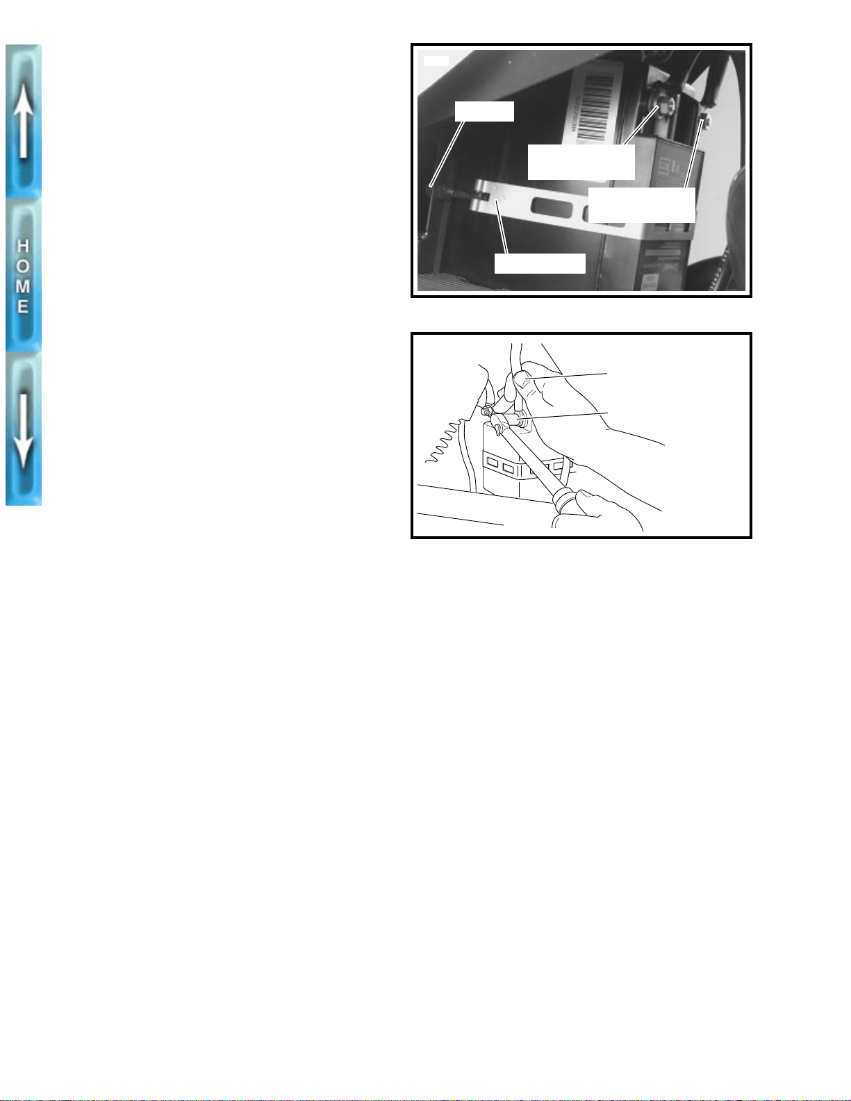
REMOVAL
WARNING
1
To avoid accidental start-up of vehicle and possible personal injury, disconnect the battery cables before proceeding. Always disconnect the negative cable first. If
the positive cable should contact ground with the negative cable installed, the resulting sparks may cause a battery explosion producing personal injury.
CAUTION
1
See Figure 1-8. Hold battery cable when loosening bat-
tery terminal hardware. Failure to hold cable will cause
battery damage.
1. Disconnect battery cables, negative cable first.
2. Remove battery strap locknut using 7/16 in. flex socket
(SNAP-ON Part No. TMU141) and handle (SNAP-ON
Part No. TM62B).
NOTE
On California models, detach carbon canister from bracket
before removing battery.
3. Remove battery from left side.
5548
b0189x7x
Locknut
Battery positive
terminal (metric)
Battery negative
terminal (metric)
Battery strap
Figure 1-7. Battery
Hold cable during
removal/installation
Tighten to 30-40 in-lbs
(3.4-4.5 Nm)
INSTALLATION
1. Clean cable connectors and battery terminals using a
wire brush or sandpaper to remove any oxidation.
1
WARNING
Always connect positive battery cable first. If the positive
cable should contact ground with the negative cable
installed, the resulting sparks may cause a battery explosion resulting in personal injury.
CAUTION
1
Connect cables to correct terminals of battery or serious
damage to motorcycle electrical system will occur.
2. Connect positive cable to positive (+) battery terminal.
Then, after positive cable has been connected to positive
terminal, connect negative cable to negative (-) battery
terminal.
CAUTION
1
See Figure 1-8. Hold battery cable when tightening bat-
tery terminal hardware. Failure to hold cable will cause
battery damage.
3. Tighten battery hardware to 30-40
4. Apply light coat of petroleum jelly or corrosion-retardant
material to both terminals.
in-lbs
(3.4-4.5 Nm).
Figure 1-8. Checking Battery Terminals
NOTE
On California models, attach carbon canister to bracket after
installing battery.
1-14
Page 55
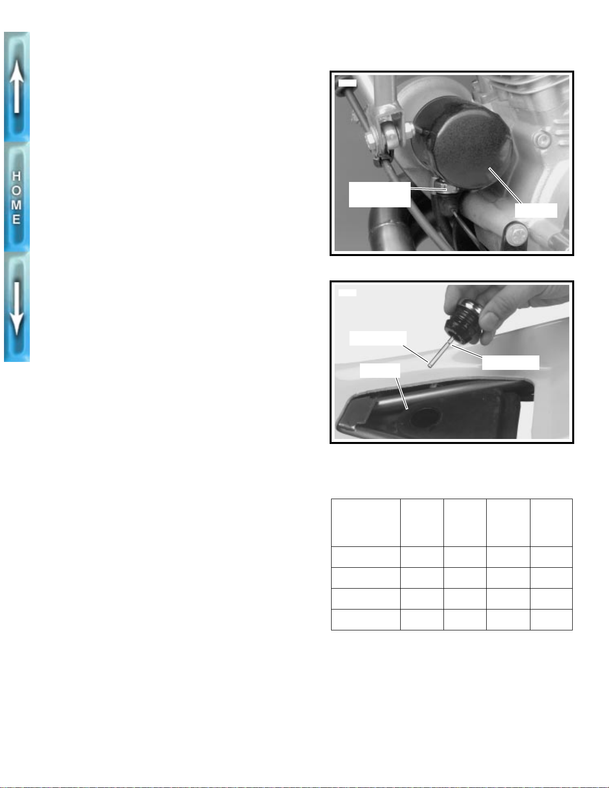
ENGINE LUBRICATION SYSTEM
CHECKING ENGINE OIL LEVEL
Check engine oil level:
At least once every 500 miles (800 km).
●
●
At every service interval.
NOTE
If engine uses more oil than normal or if vehicle is operated
under harsh conditions, check oil more frequently.
When checking or changing engine oil:
●
Warm vehicle to normal operating temperature.
●
Turn engine off.
●
Hold motorcycle upright (not leaning on side stand) on a
level surface.
1. Remove seat.
2. See Figure 1-10. Remove filler cap/dipstick from oil tank.
Wipe dipstick clean.
3. Install filler cap onto oil tank. Make sure cap is fully
seated on tank.
CAUTION
1
Do not switch oil brands indiscriminately because some
oils interact chemically when mixed. Use of inferior oils
or non-detergent oils can damage the engine.
5582
Oil pressure
switch
Oil filter
Figure 1-9. Oil Filter and Mount
5545
Lower mark
Upper mark
Oil tank
4. Remove filler cap again and check oil level on dipstick.
Oil level should be between lower and upper dipstick
level marks. If oil level in tank is below lower mark of dipstick, add oil to tank. Install filler cap/dipstick.
Recommended viscosity depends upon ambient temperature. See Table 1-4.
NOTE
Difference between upper and lower dipstick marks is
0.5 quart (0.47 liter).
1
WARNING
After installing seat, pull upward on front of seat to be
sure it is locked in position. If seat is loose, it could shift
during vehicle operation and startle the rider, causing
loss of control and personal injury.
5. Install seat.
Figure 1-10. Checking Oil Tank Level
Table 1-4. Recommended Oil Grades
HARLEY-
DAVIDSON TYPE
H.D. Multi-Grade
H.D. Multi-Grade
H.D. Regular Heavy
H.D. Extra Heavy
VISCOSITY
SAE
10W40
SAE
20W50
SAE
50
SAE
60
HARLEY-
DAVIDSON
RATING
HD 240
HD 240
HD 240
HD 240
LOWEST
AMBIENT
TEMP.
Below 40
(4°C)
Above 40
(4°C)
Above 60
(16°C)
Above 80
(27°C)
°
F
°
°
°
COLD
WEATHER
STARTS
BELOW
50° F
Excellent
Good
Poor
Poor
1-15
Page 56
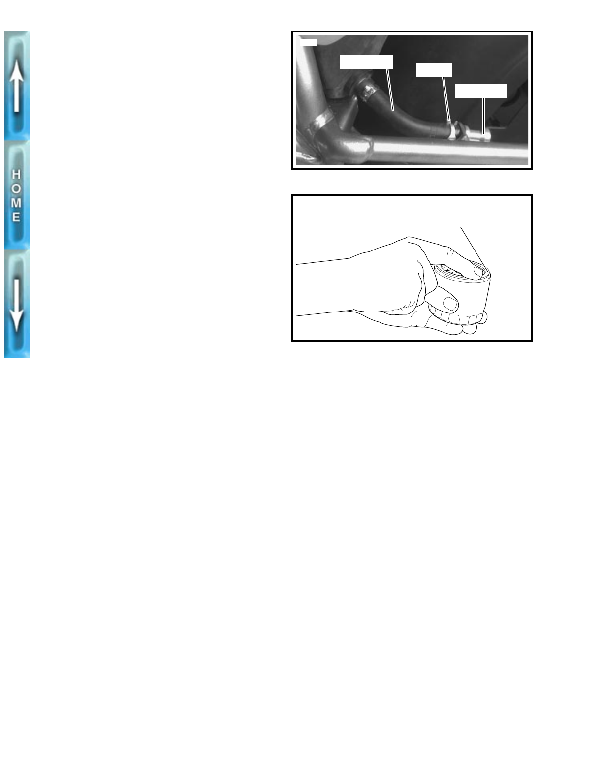
CHANGING ENGINE OIL AND FIL TER
Change engine oil:
●
At the 500 mile (800 km) service interval.
At every 5000 mile (8000 km) service interval thereafter.
●
●
When storing or removing the motorcycle for the season.
NOTE
The colder the weather, the shorter the recommended oil
change interval. A vehicle used only for short runs in cold
weather must have the engine oil drained more frequently.
5547
Drain hose
Clamp
Drain plug
1. Place a suitable container under the motorcycle.
2. See Figure 1-11. Compress clamp. Remove hose from
drain plug by pulling hose forward. Direct hose to container and completely drain oil tank.
3. Install drain hose on drain plug. Tighten clamp.
4. Remove oil filter using OIL FILTER WRENCH (Part No.
HD-41215).
5. Clean filter gasket contact surface on crankcase . Surface
should be smooth and free of any debris or old gasket
material.
6. See Figure 1-12. Apply a thin film of oil to gasket contact
surface on crankcase mounting plate and to
7. Pour 4.0 ounces (0.12 liter) of clean oil into
when changing oil.
8. Screw filter onto adapter until gasket contacts mounting
plate surface. Apply another 1/2-3/4 turn by hand.
WARNING
1
Be sure no oil gets on tires when changing oil and filter.
Traction will be adversely affected which may lead to a
loss of control and personal injury.
9. Fill oil tank with an oil from Table 1-4. Oil tank capacity is
2.0 quarts (1.90 liters) plus the 4.0 ounces (0.12 liter)
added in Step 7.
10. Install filler cap onto oil tank. Make sure filler cap is fully
seated.
new
oil filter.
new
filter
b0138aox
Figure 1-11. Oil Tank Drain Line
Apply a thin film of oil to new filter gasket
and crankcase mounting plate.
Figure 1-12. Oil Filter
1
WARNING
After installing seat, pull upward on front of seat to be
sure it is locked in position. If seat is loose, it could shift
during vehicle operation and startle the rider, causing
loss of control and personal injury.
11. Install seat.
12. Start engine. Verify that oil pressure signal light on dash
panel turns off when engine speed is 1000 RPM or
above.
13. Check for oil leaks at oil filter and drain hose.
14. Check oil level as described on page 1-15.
1-16
Page 57
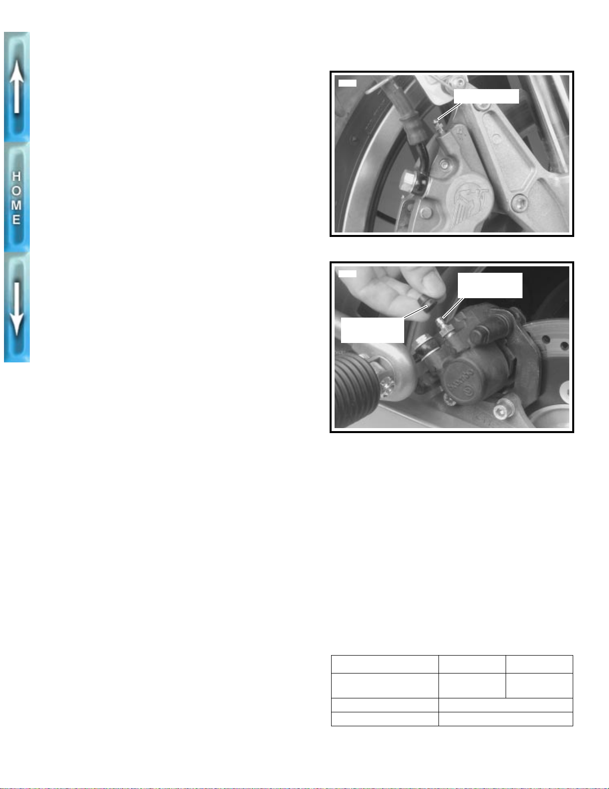
BRAKES
GENERAL
WARNING
1
Brake fluid can cause irritation of eyes and skin, and may
be harmful if swallowed. If fluid is swallowed, induce
vomiting by administering two tablespoons of salt in a
glass of warm water. Call a doctor. In case of contact with
skin or eyes, flush with plenty of water. Get medical
attention for eyes. KEEP BRAKE FLUID OUT OF THE
REACH OF CHILDREN.
Check brake fluid level and condition:
●
At the 500 mile (800 km) service interval.
At every 5000 mile (8000 km) service interval thereafter.
●
When storing or removing the motorcycle for the season.
●
Front brake hand lever and rear brake foot pedal must have a
firm feel when brakes are applied. If not, bleed system as
described.
BLEEDING BRAKES
NOTE
Hydraulic brake fluid bladder-type pressure equipment can be
used to fill brake master cylinder through the bleeder valve.
Remove master cylinder reservoir cover so that system cannot pressurize. Do not use pressure bleeding equipment
when the hydraulic system is sealed with master cylinder reservoir cover and gasket in place.
5565
Bleeder valve
Figure 1-13. Front Brake Caliper Bleeder Valve
5566
Protective
cap removed
Bleeder valve
(metric)
1. Install end of a length of plastic tubing over caliper
bleeder valve; place other end in a clean container.
Stand motorcycle upright.
a. Front brake caliper-Figure 1-13.
b. Rear brake caliper-Figure 1-14.
2. Add D.O.T. 5 SILICONE HYDRAULIC BRAKE FLUID to
master cylinder reservoir. Do not reuse brake fluid.
a. Bring fluid level to within 1/8 in. (3.2 mm) of molded
boss for front master cylinder reservoir .
b. Bring fluid level between upper and lower marks for
rear master cylinder reservoir.
3. Depress and hold brake lever/pedal to build up hydraulic
pressure.
4. Open bleeder valve about 1/2-turn counterclockwise;
brake fluid will flow from bleeder valve and through tubing. When brake lever/pedal has moved 1/2-3/4 of its full
range of travel, close bleeder valve (clockwise). Allow
brake lever/pedal to return slowly to its released position.
5. Repeat Steps 2-4 until all air bubbles are purged.
6. Tighten bleeder valves.
a. Front bleeder valve to 4-6 ft-lbs (5.4-8.1 Nm).
b. Rear bleeder valve to 6-9 ft-lbs (8.1-12.2 Nm).
7. Verify master cylinder fluid level as described in Step 2.
8. Tighten master cylinder reservoir cover screws to 9-13
in-lbs
(1.0-1.5 Nm). Install cover on rear reservoir.
Figure 1-14. Rear Brake Caliper Bleeder Valve
PADS, ROTORS AND LINKAGE
Check brake pads and rotors for minimum thickness. See
Table 1-5. See Section 2 for replacement procedures.
At the 500 mile (800 km) service interval.
●
At every service interval thereafter.
●
Check rear brake pedal height and freeplay. See Table 1-5.
See Section 2 for adjustment procedures.
Before every ride.
●
At the 500 mile (800 km) service interval.
●
At every 5000 mile (8000 km) service interval thereafter.
●
Table 1-5. Brake System Components
SPECIFICATION FRONT REAR
Minimum rotor thickness 0.17 in.
(4.4 mm)
Minimum pad thickness 1/16 in. (1.6 mm)
Hand lever/pedal freeplay 1/8 in. (3.2 mm) maximum
0.19 in.
(4.8 mm)
1-17
Page 58
TIRES AND WHEELS
TIRE INFLATION
WARNING
1
Do not inflate any tire beyond its maxim um inflation pressure as specified on tire sidewall. Overinflation may
cause tire to suddenly deflate leading to personal injury.
Check tire pressure and tread:
●
Before every ride.
●
At the 500 (800 km) mile service interval.
●
At every scheduled service interval.
Check for proper front and rear tire pressures when tires are
cold. Compare pressure against Table 1-6.
Table 1-6. Tire Pressures
TIRE AND POSITION
Front-Dunlop Sportmax
Radial II 120/70 ZR 17
Rear-Dunlop Sportmax
Radial II 170/60 ZR 17
PRESSURE
FOR SOLO
RIDING
32 PSI
(2.2 bar)
36 PSI
(2.5 bar)
PRESSURE
AT GVWR
36 PSI
(2.5 bar)
38 PSI
(2.8 bar)
WHEEL BEARINGS
Check wheel bearings:
Every time the wheel is removed.
●
At every 10,000 mile (16,000 km) service interval.
●
When storing or removing the motorcycle for the season.
●
Check wheel bearings and axle spacers for wear and corrosion. Excessive play or roughness indicates worn bearings.
Replace bearings in sets only.
SPEEDOMETER CABLE
Check speedometer cable:
●
Inspect before every ride.
●
Lubricate at every 5000 mile (8000 km) service interval.
Examine speedometer cable housing (outer sheath) for kinks
or other damage. Replace entire cable assembly if any damage is noted.
Lubricate inner cable with a good quality graphite grease.
Wipe off excess grease.
1-18
Page 59
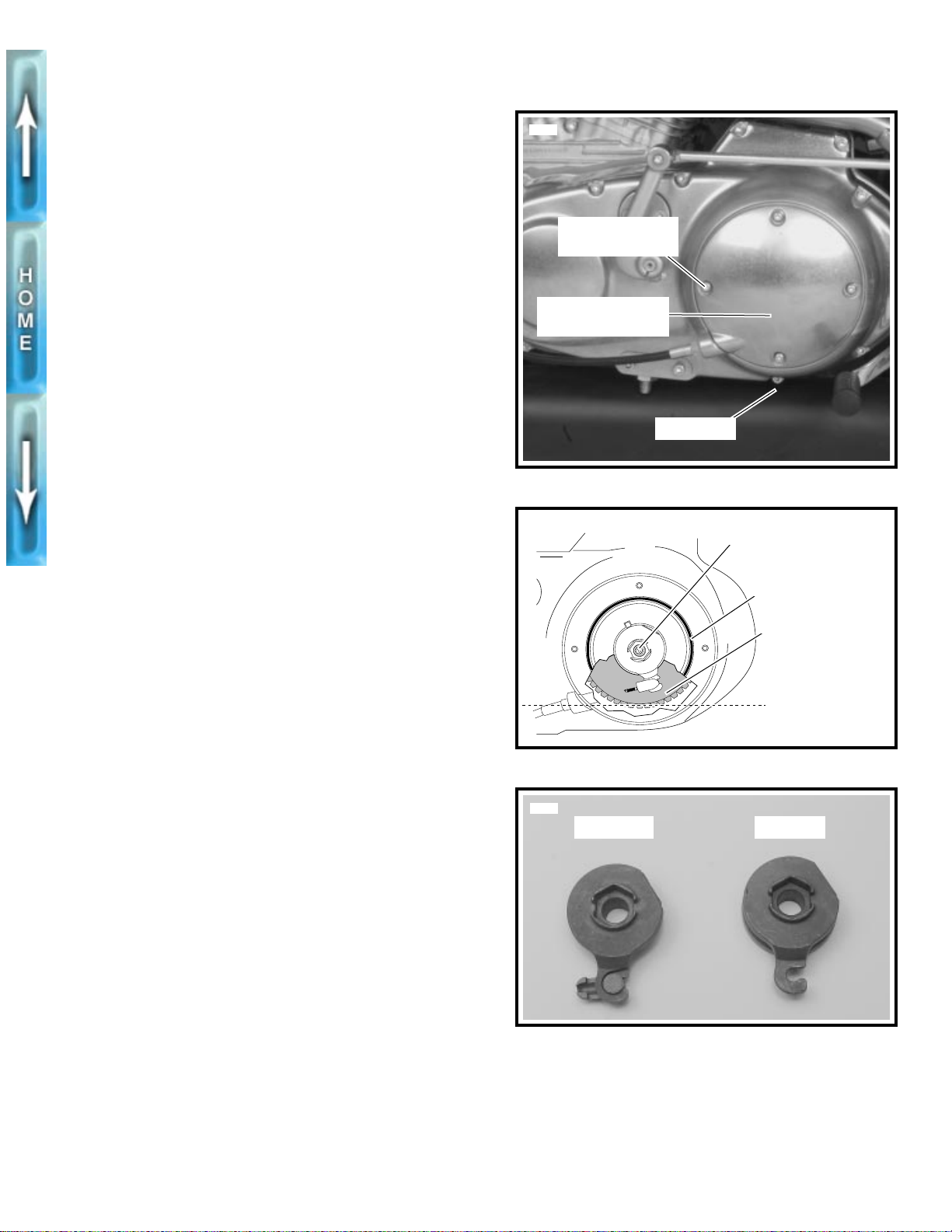
CLUTCH
TRANSMISSION FLUID
Check transmission fluid:
Replace at the 500 mile (800 km) service interval.
●
●
Inspect level at e v ery 2500 mile (4000 km) service interval.
●
Replace at every 5000 mile (8000 km) service interval.
Primary chaincase lubricant capacity is approximately 1.0
quart (0.95 liter). For best results, drain lubricant while hot.
1. Raise rear of vehicle off the floor using REAR WHEEL
SUPPORT STAND (Part No. B-41174) to prevent chain-
case lubricant from draining out of clutch cover opening
when refilled.
2. Remove muffler . See EXHAUST SYSTEM in Section 2.
3. See Figure 1-15. Position a suitable container under
transmission lubricant drain plug. Remove drain plug and
drain lubricant.
4. Remove foreign material from magnetic drain plug.
Reinstall plug and tighten to 14-21 ft-lbs (19-28 Nm).
5. Remove four TORX screws with washers from clutch
inspection cover. Remove clutch inspection cover from
primary cover. Do not damage or dislodge Quad ring
from primary cover.
5592
Torx screw with
washer (4)
Clutch inspection
b0190x6x
cover
Drain plug
Figure 1-15. Primary Cover
Clutch adjusting screw
Quad ring
Diaphragm spring
CAUTION
1
Do not overfill the primary chaincase with lubricant.
Overfilling may cause rough clutch engagement and
incomplete disengagement (or clutch drag).
6. Add SPORT-TRANS FLUID (Part No. 98854-96 quart
size; Part No. 98855-96 gallon size) as required until
lubricant is even with bottom of clutch diaphragm spring.
See Figure 1-16.
7. Install clutch inspection cover using four TORX screws
with washers. Tighten screws in a crosswise pattern to 79 ft-lbs (9-12 Nm).
8. Install muffler. See EXHAUST SYSTEM in Section 2.
PRODUCTION CHANGE
See Figure 1-17. Beginning with motorcycles built in early
January 1996, the outer clutch release ramp has been
changed. The clutch adjustment and lever freeplay procedures remain the same. The change was made to prevent an y
possible contact between the coupler and the primary cover.
Lubricant level
Figure 1-16. Lubricant Level
5671
New style Old style
Figure 1-17. Ramp Change
1-19
Page 60
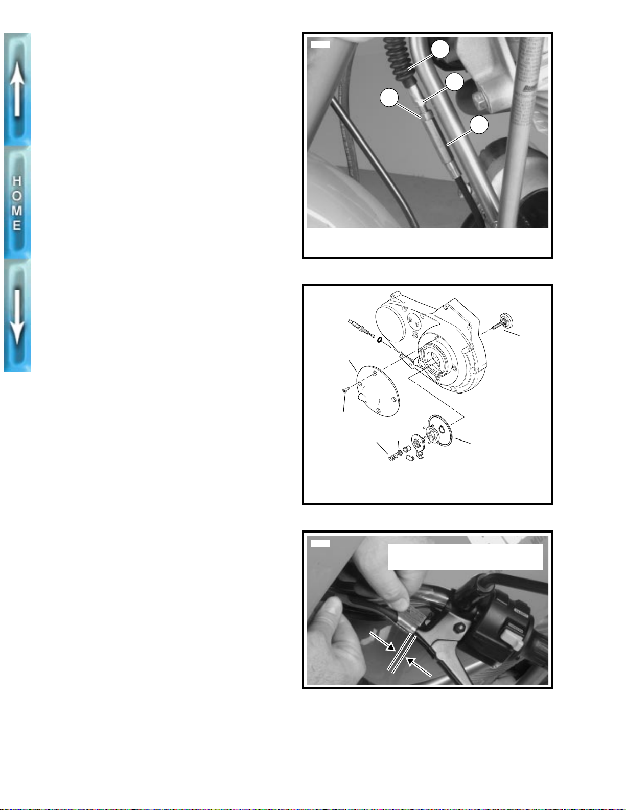
ADJUSTMENT
Check clutch adjustment:
●
At the 500 mile (800 km) service interval.
●
At every 5000 mile (8000 km) service interval thereafter.
If clutch slips under load or drags when released, first check
control cable adjustment. If cable adjustment is within specifications, adjust clutch mechanism as described below.
When necessary, lubricate cable with LUBIT-8 TUFOIL
CHAIN AND CABLE LUBE (Part No. HD-94968-85TV).
1. Raise rear of vehicle off the floor using REAR WHEEL
SUPPORT STAND (Part No. B-41174).
2. See Figure 1-18. Slide rubber boot (1) upward to expose
adjuster mechanism. Loosen jam nut (3) from adjuster
(4). Turn adjuster to shorten cable housing until there is a
large amount of freeplay at clutch hand lever.
3. See Figure 1-19. Remove TORX screws with w ashers (1)
from clutch inspection cover (2). Remove clutch inspection cover from primary cover, but leave Quad ring (3) in
place.
NOTE
Quad ring removed from primary cover for illustrative purposes only in Figure 1-19.
5594
1
2
3
4
®
1. Rubber boot
2. Cable end
Figure 1-18. Clutch Cable Adjuster Mechanism
b0152x6x
3. Jam nut
4. Adjuster
6
2
4. Remove spring (4) and adjusting screw lockplate (5).
Turn adjusting screw counterclockwise until it lightly bottoms.
5. Turn clutch adjusting screw (6) clockwise 1/4 turn. Install
lockplate (5) and spring (4) on adjusting screw flats. If
hex on lockplate does not align with recess in outer ramp ,
rotate adjusting screw clockwise until it aligns.
6. Squeeze clutch lever to maximum limit three times to set
ball and ramp mechanism. Pull outer cable conduit and at
the same time adjust cable adjuster to provide 1/16-1/8 in.
(1.6-3.2 mm) freeplay at hand lever. Adjust as follows.
a. See Figure 1-20. Pull clutch cable ferrule (end of
cable housing) away from clutch hand lever bracket.
Gap between ferrule and bracket should be 1/16-1/8
in. (1.6-3.2 mm).
b. See Figure 1-18. Adjust freeplay by turning cable
adjuster (4).
c. Tighten jam nut (3) against adjuster (4).
d. Slide boot (1) over cable adjuster mechanism.
7. Change or add transmission fluid if necessary.
8. Install clutch inspection cover (2). Tighten TORX screws
with washers (1) in a crosswise pattern to 7-9 ft-lbs (912 Nm).
1
5
4
1. Torx screw with washer
2. Clutch inspection cover
3. Quad ring
Figure 1-19. Clutch Release Mechanism
5595
Adjust for 1/16-1/8 in. (1.6-3.2 mm)
gap between ferrule and bracket
3
4. Spring
5. Lockplate
6. Adjusting screw
9. Check clutch cable freeplay. See Step 6 above.
1-20
Figure 1-20. Adjusting Clutch Freeplay
Page 61
REAR BELT DEFLECTION
INSPECTION
Check rear belt deflection:
● Inspect before every ride.
● Adjust at the 500 mile (800 km) service interval.
● Adjust at every 5000 mile (8000 km) service interval
thereafter.
The secondary drive belt should be checked for unusual
wear, cracking or loss of teeth. Check the belt sprocket for
unusual wear, broken teeth or damaged flange. When checking deflection, have:
● No rider or cargo weight on motorcycle.
● Transmission in neutral.
● Belt and sprockets at room temperature.
● Motorcycle upright (not on side stand).
1. See Figure 1-21. At the lower strand, position “A”, mid-
way between transmission sprocket and rear wheel
sprocket, apply 10 Ibs (4.5 kg) of upward force on lower
span of rear belt using BELT TENSION GAUGE (Part No.
HD-35381).
2. Measure belt deflection “B” several times, each time with
belt moved (by rotating rear wheel) to a different position
on sprockets. With sprockets rotated to tightest belt position, belt deflection “B” (measured at position “A”) should
be 7/8-1 in. (22.2-25.4 mm).
b0086x6x
Belt deflection should be
B
7/8-1 in. (22.2-25.4 mm)
Figure 1-21. Checking Belt Deflection
5574
Apply 10 lbs (4.5 kg)
A
of upward force
ADJUSTMENT
1. Adjust shock absorber spring preload. See REAR PRE-
LOAD ADJUSTMENT on page 1-23.
2. See Figure 1-22. Loosen rear axle nut (metric), if not
already performed.
NOTE
After you loosen the axle nut, turn the axle and nut so the rearmost flat on each side is parallel with the ends of the swingarm.
Check to be sure rear wheel axle is parallel with swingarm
pivot shaft.
3. See Figure 1-23. Measure each side from the flat to the
end of the swingarm, to be sure rear axle is correctly
located.
4. Turn axle adjuster nuts (metric) on each side of swing-
arm to adjust belt deflection.
a. Turn clockwise to decrease deflection (increase ten-
sion).
b. Turn counterclockwise to increase belt deflection
(decrease tension).
Turn each adjuster nut exactly the same number of turns
to maintain rear wheel alignment
5. Tighten axle nut (metric) to 66-73 ft-lbs (89.5-98.9 Nm).
Axle adjuster nut
Rear axle nut
Figure 1-22. Rear Axle
5585
Measure each side to
check wheel alignment
Figure 1-23. Checking Rear Wheel Alignment,
Right Side Shown
CLEANING
Keep dirt, grease, oil, and debris off the belt and sprockets.
Clean the belt with a rag which is slightly damp with light
cleaning agent.
1-21
Page 62
PRIMARY CHAIN
INSPECTION
Check primary chain:
● At the 500 mile (800 km) service interval.
● At every 5000 mile (8000 km) service interval thereafter.
Check primary chain for correct tension by measuring its vertical freeplay through the primary chain inspection cover
opening located near the top of the primary cover.
1. See Figure 1-24. Remove two scre ws from primary chain
inspection cover.
2. Remove primary chain inspection cover.
3. See Figure 1-25. Check primary chain tension by mea-
suring vertical freeplay (measuring midway between
sprockets) several times, each time with primary chain
moved (by rotating engine) to a different position on
sprockets.
4. Check primary chain tension against Table 1-7. If neces-
sary, adjust as described below.
NOTE
●
Measurements are taken with sprockets rotated to tightest chain position.
●
The initial primary chain vertical freeplay specification
used at the assembly plant is 1/4-1/2 in. (6.3-12.7 mm)
with a cold engine. The 1/4 in. (6.3 mm) minimum is only
allowed at the absolute tightest point in the drive, as
measured with specialized factory equipment. If a chain
has less than 1/4 in. vertical freeplay (with a cold
engine), adjust freeplay to the “field” specification of 3/81/2 in. (9.5-12.7 mm).The looser specification will avoid
overtightening, which might otherwise occur during
adjustment using “non-factory” equipment and methods.
Table 1-7. Primary Chain Tension
5583
b0085x6x
Primary chain
inspection cover
Screws
Figure 1-24. Primary Chain Inspection Cover
Front sprocket
Figure 1-25. Measuring Primary Chain Tension
Rear sprocket
ENGINE TEMPERA TURE FREEPLA Y
Cold 3/8-1/2 in.
(9.5-12.7 mm)
Hot (normal running temperature) 1/4-3/8 in.
(6.4-9.5 mm)
5. Install primary chain inspection cover. Tighten screws to
40-60 in-lbs (4.5-6.8 Nm).
ADJUSTMENT
NOTE
If vertical freeplay cannot be set within the limits specified,
then primary chain and/or chain adjuster are worn beyond
adjustment limits. Replace parts as necessary. See Section 6.
1. See Figure 1-26. Loosen locknut and turn adjusting
screw:
a. Turn clockwise (inward) to reduce freeplay.
b. Turn counterclockwise (outward) to increase free-
play.
2. Tighten locknut to 20-25 ft-lbs (27.1-33.9 Nm).
1-22
5592
Locknut
Adjusting screw
Figure 1-26. Primary Chain Adjustment
Page 63
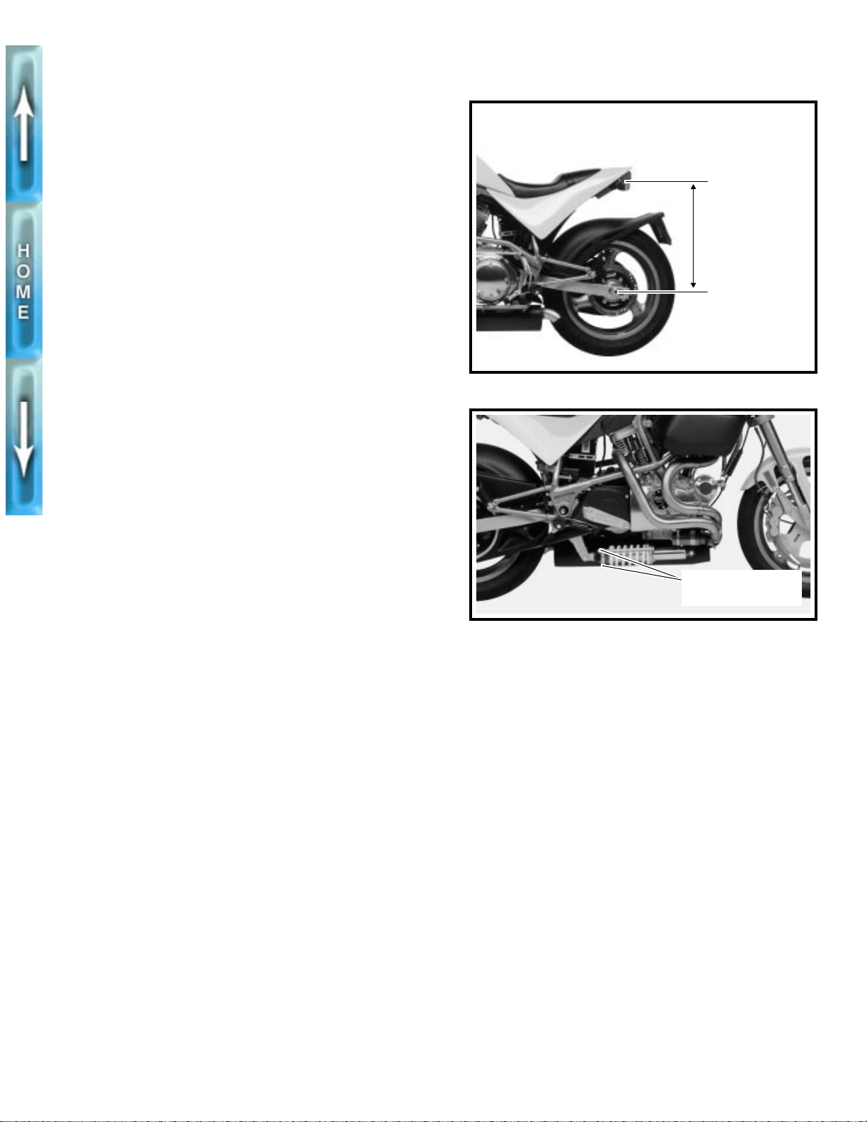
REAR PRELOAD ADJUSTMENT
GENERAL
Adjust rear preload:
● When a new rider buys the motorcycle.
● When there is a change in load (luggage, etc.)
● Before changing front fork or rear shock suspension
settings.
Rear suspension spring preload assures that the rear suspension has the proper amount of travel.
Spring preload is the most important suspension adjustment
on the S1 Lightning. Improper preload will adversely affect
both the handling and motorcycle ride. Correct preload setting will result in motorcycle handling that suits the rider’s size
and weight.
ADJUSTMENT
You will need three people to carry out this adjustment.
1. Verify correct front and rear tire pressure. See TIRES
AND WHEELS on page 1-18.
2. Remove all accessories from motorcycle including tank
bag and/or saddlebags.
3. Take the motorcycle off the side stand and bounce the
rear up and down a few times to be sure the suspension
is free and not binding.
4. See Figure 1-27. Measure the distance from the center
of the rear axle nut to the rear turn signal mounting bolt
without rider/passenger/cargo/accessories on the motorcycle.
5. Install items removed in Step 2. Load all cargo.
6. Bounce a few times on the seat to be sure the suspension is free and not binding.
7. With the help of an assistant, take the same measurement with the vehicle fully loaded (rider/passenger/luggage/cargo). The assistant should help balance the
motorcycle so the rider can keep both feet on the footrests.
8. Subtract the second measurement from the first. The difference, which is the squat, should be 0.25-0.75 in. (6.4-
19.1 mm). If it is not, you will have to adjust the spring
preload.
1CAUTION
● Be sure to apply the same number of turns to each
mechanical preload adjusting nut to ensure that the
end plates do not become misaligned. Misaligned
end plates will cause the shock absorber spring to
bind against the adjustment rods.
● Be sure the plates are parallel within 1/64 in. (0.4 mm).
Misaligned end plates will cause the shock absorber
spring to bind against the adjustment rods.
9. See Figure 1-28. Change the spring preload by adjusting
the mechanical preload adjusting nuts (metric) on the
rods that connect the end plates.
a. Increase the preload by tightening the nuts.
b. Decrease the preload by loosening the nuts.
5540
Rear turn signal
mounting bolt
Rear axle nut
Figure 1-27. Checking Rear Preload
Preload adjusting
nuts (metric)
Figure 1-28. Adjusting Rear Preload
1-23
Page 64
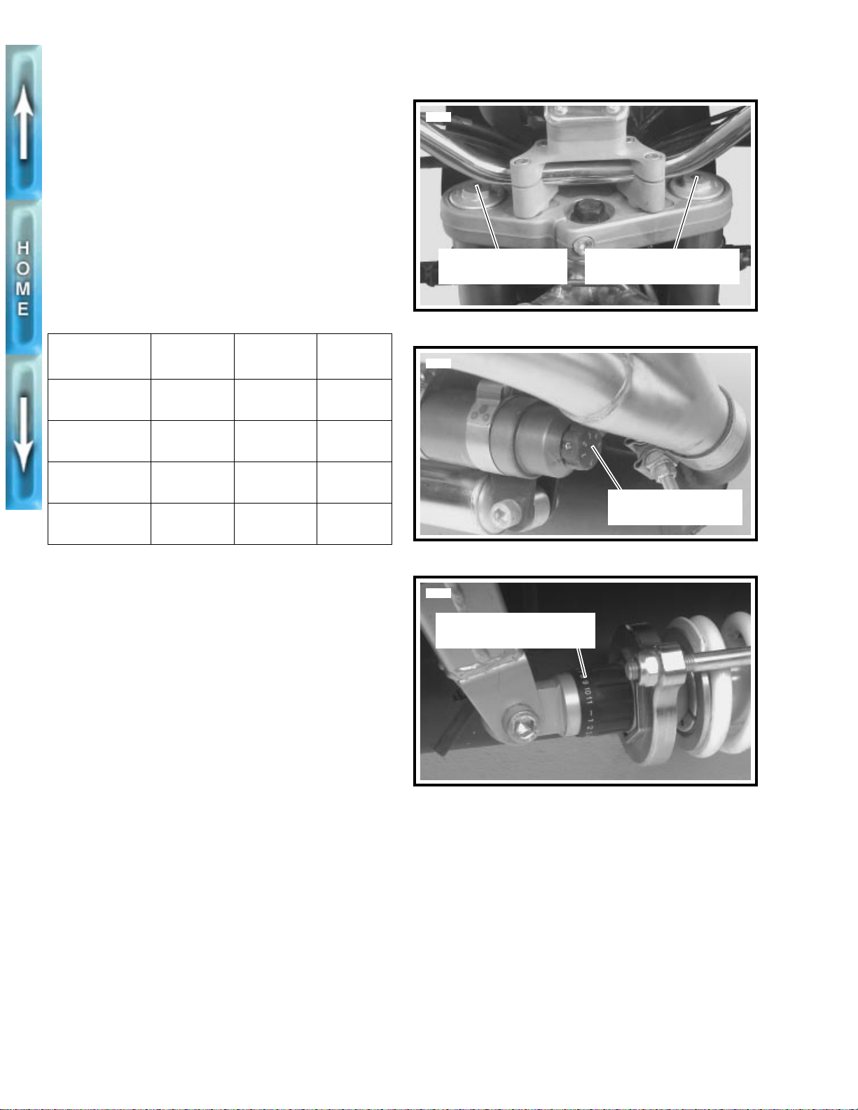
SUSPENSION
ADJUSTMENT
Adjust front forks by first turning the slotted dial clockwise with
a screwdriver until it stops. Then turn the dial counterclockwise the recommended 12 or 20 positions. A higher number
of clicks increases damping.
NOTE
Rear spring preload must be set before adjusting any other
suspension settings. See REAR PRELOAD ADJUSTMENT
on page 1-23.
Table 1-8. Suspension Settings
ADJUSTMENT
Front fork
compression
Front fork
rebound
Rear shock
rebound
Rear shock
compression
RANGE IN
CLICKS
28 20 1-29
28 12 1-29
731-30
11 5 1-31
F ACT OR Y
SETTING
SEE
FIGURE
5542
Front fork rebound
damping adjuster
Figure 1-29. Front Fork Adjustments
5572
Figure 1-30. Rear Shock Rebound Adjuster
Front fork compression
damping adjuster
Rear shock rebound
damping adjuster
REAR SHOCK
Check rear shock:
● At the 500 mile (800 km) service interval.
● At every 5000 mile (8000 km) service interval thereafter.
Inspect the rear shock absorber for loose mounting hardware ,
leaks or rod-to-spring contact. Tighten the front and rear
mounts 40-45 ft-lbs (54.2-61.0 Nm).
5571
Rear shock compression
damping adjuster
Figure 1-31. Rear Shock Compression Adjuster
1-24
Page 65
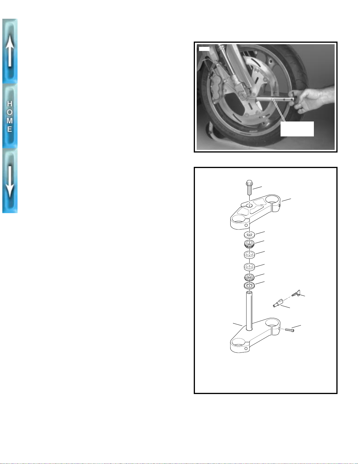
FRONT FORK
STEERING HEAD BEARINGS
Check steering head bearings:
● At the 500 mile (800 km) service interval.
● At every 5000 mile (8000 km) service interval thereafter.
● Lubricate every 10,000 mile (16,000 km) service interval.
1. See Figure 1-32. Lift motorcycle using FRONT WHEEL
SUPPORT STAND (Part No. B-41395) and S1 LIFT
ADAPTER (Part No. B-41686) so front wheel is off the
ground.
2. Turn front wheel to full right lock.
3. Hook a spring scale into the axle hole and pull front
wheel to center position.
It should take 3.5-5.5 lbs (1.6-2.5 kg) to pull front wheel
to center.
NOTE
Check that clutch and throttle cables do not bind when measuring bearing resistance.
Lubrication
At 10,000 miles (16,000 km) and every 10,000 miles
(16,000 km) thereafter, grease the steering head bearings
with WHEEL BEARING GREASE (Part No. 99855-89).
See FORK STEM AND BRACKET ASSEMBLY in Section 2
for lubrication procedure.
5591
3.5-5.5 lbs
(1.6-2.5 kg)
Figure 1-32. Checking Steering Head Bearings
b0031a2x
1
2
3
4
5
ADJUSTMENT
1. Raise front wheel off floor using FRONT WHEEL SUP-
PORT STAND (Part No. B-41395) and S1 LIFT
ADAPTER (Part No. B-41686).
2. Turn front wheel to full right lock.
3. See Figure 1-32. Hook spring scale into front axle hole.
Pull front wheel to center position. It should take 3.5-5.5
lbs (1.6-2.5 kg) to pull front wheel to center.
4. Loosen pinch screws (7) on upper and lower triple
clamps.
5. See Figure 1-33. Tighten or loosen fork stem bolt (1) to
set proper tension.
6. Recheck tension using spring scale. See Step 3.
7. Tighten triple clamp pinch screws (7) to 18-20 ft-lbs (24.4-
27.1 Nm).
6
1. Fork stem bolt
2. Upper triple clamp
3. Dust shield (2)
4. Roller bearing (2)
5. Bearing cup (2)
Figure 1-33. Steering Head Assembly
5
4
3
9
8
7
6. Lower triple clamp
7. Screw (5)
8. Steering head lock
9. Steering lock key
1-25
Page 66
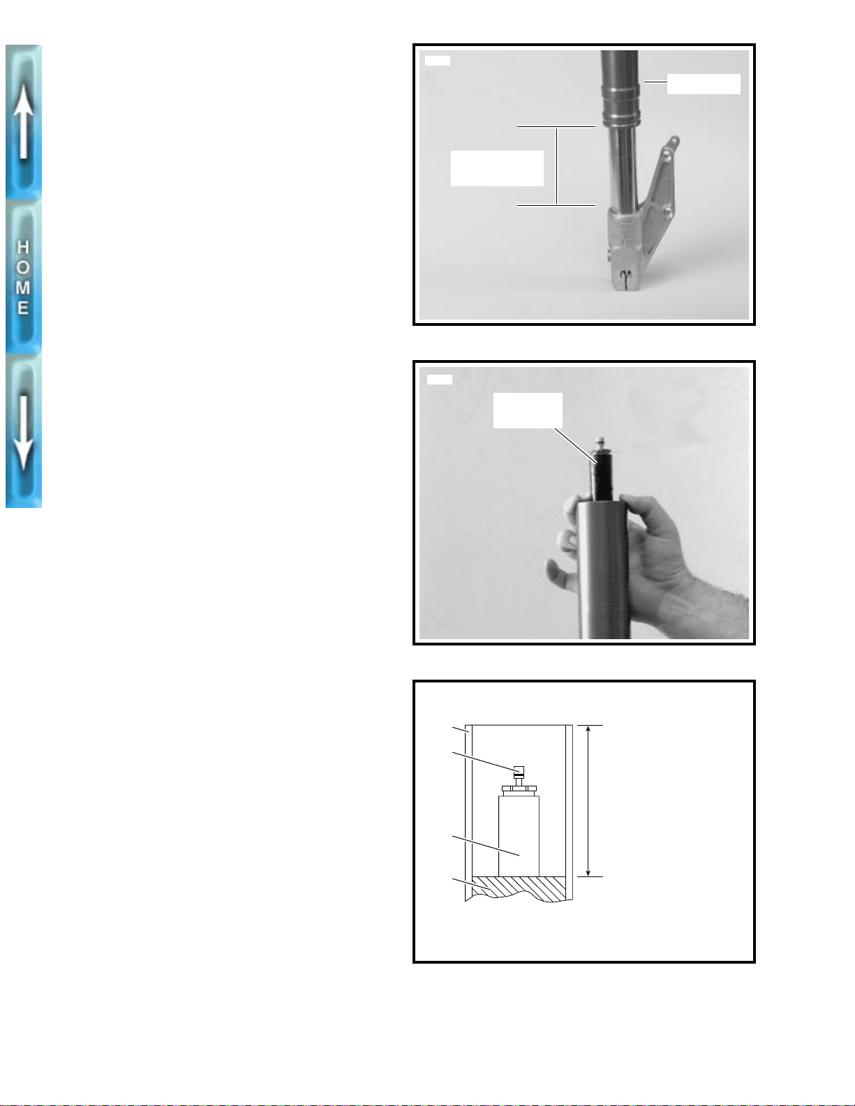
FORK OIL CHANGE
Replace fork oil:
● At every 10,000 mile (16,000 km) service interval.
● If fork should be submerged in water.
1. Remove and disassemble front forks. See FRONT FORK
in Section 2.
NOTE
If fork oil is emulsified, aerated or light brown in color, then it
has been contaminated by water. If this happens, replace the
fork oil seals.
2. Drain forks of oil.
5750
Outer tube
9 in. (229 mm)
maximum
3. With fork in fully compressed stage, add WP FORK OIL,
5 WEIGHT to above red retaining cap.
1CAUTION
See Figure 1-34. Raise outer tube no higher than 9 in.
(229 mm) or fluid loss will occur.
4. See Figure 1-35. Grasp damper assembly by the
adjuster. Pull damper assembly through several full
strokes to bleed air from the fork.
5. With front fork fully compressed, clamp vertically in
FRONT FORK HOLDING TOOL (Part No. B-41177).
6. Measure distance from fork oil surface to top of tube
using PRO-LEVEL OIL GAUGE (Part No. B-59000A).
Add or drain fork oil as needed until distance from top of
fork tube to oil surface measures 4.33 in. (110 mm). See
Figure 1-36.
7. Assemble front fork and install. See FRONT FORK in
Section 2.
Figure 1-34. Maximum Outer Tube Lift
5758
Damper
assembly
Figure 1-35. Bleeding Fork
b0038bx2x
1
1-26
2
3
4
1. Outer tube
2. Adjuster
Figure 1-36. Correct Fork Oil Level
Correct fork oil level is
4.33 in. (110 mm) below
top of fork tube
Use only
WP FORK OIL, 5 WEIGHT
3. Damper assembly
4. Fork oil level
Page 67
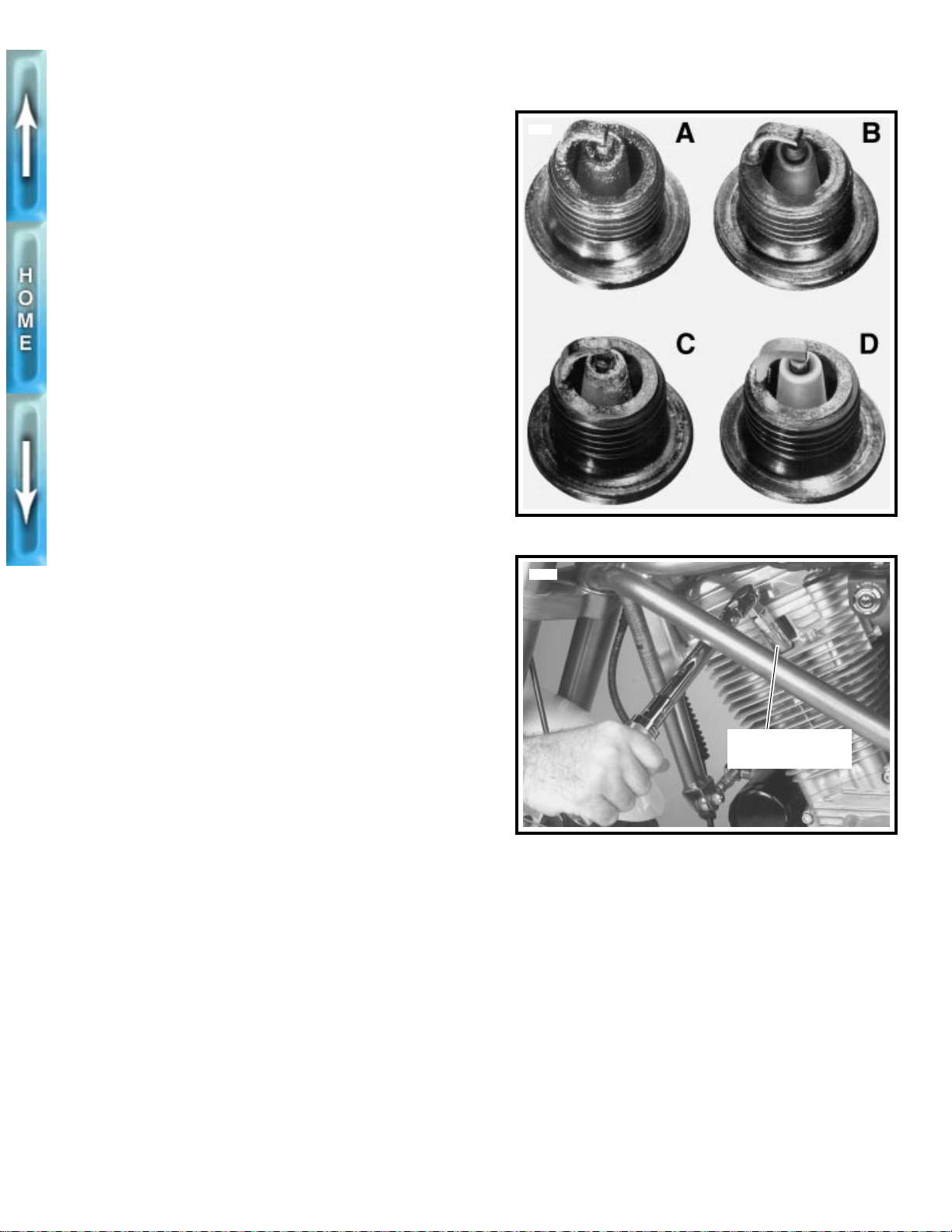
SPARK PLUGS
INSPECTION
Check spark plugs:
● Inspect at every 5000 mile (8000 km) service interval.
● Replace every 10,000 mile (16,000 km) service interval.
1. Disconnect cables from both spark plugs.
2. Remove spark plugs.
3. See Figure 1-37. Compare your observations of the plug
deposits with the descriptions provided below.
a. A wet, black and shiny deposit on plug base, elec-
trodes and ceramic insulator tip indicates an oil
fouled plug. The condition may be caused by one or
more of the following: worn pistons, worn piston
rings, worn valves, worn valve guides, worn valve
seals, a weak battery or a faulty ignition system.
b. A dry, fluffy or sooty black deposit indicates a carbu-
retor air-fuel mixture that is too rich, engine idling for
excessive periods of time and/or enrichener usage
for excessive periods of time.
c. A light brown, glassy deposit indicates an over-
heated plug. This condition may be accompanied by
cracks in the insulator or by erosion of the electrodes and is caused by an air-fuel mixture that is
too lean, a hot-running engine, valves not seating or
improper ignition timing. The glassy deposit on the
spark plug is a conductor when hot and may cause
high-speed misfiring. A plug with eroded electrodes,
heavy deposits or a cracked insulator must be
replaced.
4636
Figure 1-37. Typical Spark Plug Deposits
5581
d. A plug with a white, yellow, tan or rusty brown pow-
dery deposit indicates balanced combustion. Clean
off spark plug deposits at regular intervals.
4. If the plugs require cleaning between tune-ups, proceed
as follows:
a. Degrease firing end of spar k plug using ELECTRI-
CAL CONTACT CLEANER. Dry plug with compressed air.
b. Use a thin file to flatten spark plug electrodes. A
spark plug with sharp edges on its electrodes
requires 25%-40% less firing voltage than one with
rounded edges.
5. If the plugs cannot be cleaned, replace with No. 6R12
spark plugs.
6. Check electrode gap with a wire-type feeler gauge. Gap
should be 0.038-0.045 in. (0.96-1.14 mm).
7. See Figure 1-38. Apply LOCTITE ANTI-SEIZE to plugs.
Install and tighten spark plugs to 11-18 ft-lbs (15-24 Nm).
8. Connect spark plug cables. Verify that cables are
securely connected to coil and spark plugs.
Tighten to 11-18
ft-lbs (15-24 Nm)
Figure 1-38. Spark Plugs
1-27
Page 68
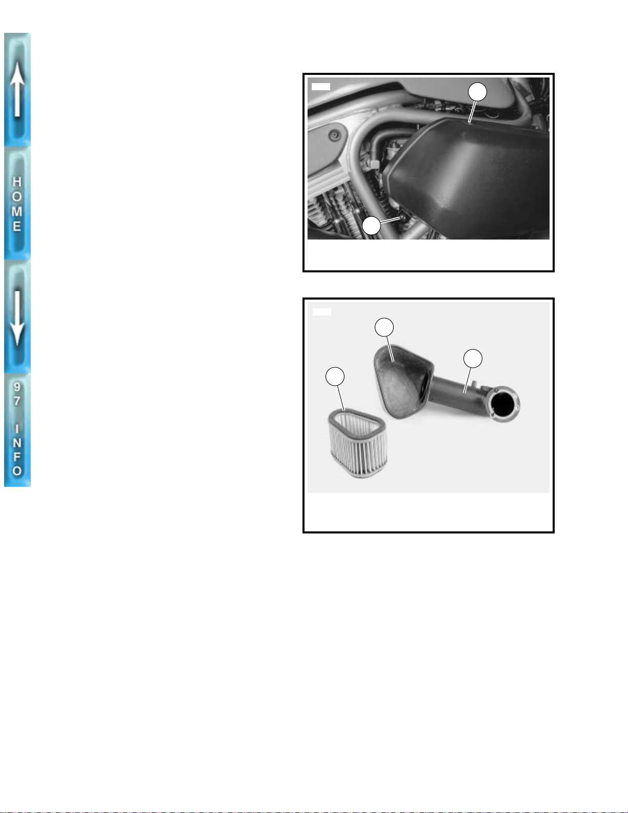
AIR CLEANER FILTER
REMOVAL
Check air cleaner filter:
● Inspect at the 500 mile (800 km) service interval.
● Replace at every 5000 mile (8000 km) service interval
thereafter.
NOTE
Service air cleaner more often if the motorcycle is run in a
dusty environment.
1CAUTION
Do not run engine without filter element in place. Debris
could be drawn into the engine causing damage.
1. See Figure 1-39. Remove screw and nylon washer on
top of air cleaner cover.
2. Remove screw, nylon washer and locknut at rear of air
cleaner cover. Remove cover.
3. See Figure 1-40. Remove filter box from snorkel tube.
4. Remove filter from filter box.
INSTALLATION
1. Replace filter element if damaged or if filter media cannot
be adequately cleaned.
5705
2
1. Screw and nylon washer
2. Screw, nylon washer and locknut
Figure 1-39. Air Cleaner Cover
5749
2
1
1
3
1WARNING
● Low pressure air can blow debris in your face and
eyes. Not wearing eye protection or a face shield
when using pressurized air may result in personal
injury.
● Do not use gasoline or solvents to clean the filter ele-
ment. Volatile/flammable cleaning agents may cause
an intake system fire which may result in personal
injury.
2. Wash element in luke warm water with a mild detergent.
Dry the filter element using low-pressure (32 psi/221 kPa
maximum) compressed air. Rotate element while moving
air nozzle up and down the element interior. Do not rap
the element on a hard surface.
Hold filter element up to strong light source. The element
can be considered sufficiently clean if light is uniformly
visible through the element.
3. Thoroughly clean backplate, filter box and inside of
cover.
4. See Figure 1-40. Place filter in filter box. Attach filter box
to snorkel tube.
5. See Figure 1-39. Place cover over backplate assembly.
Install top screw and nylon washer.
6. Install screw, nylon washer and locknut on rear mount.
Tighten to 6-8 ft-lbs (8.1-10.8 Nm).
1. Filter element
2. Filter box
3. Snorkel tube
Figure 1-40. Snorkel Tube
1-28
Page 69
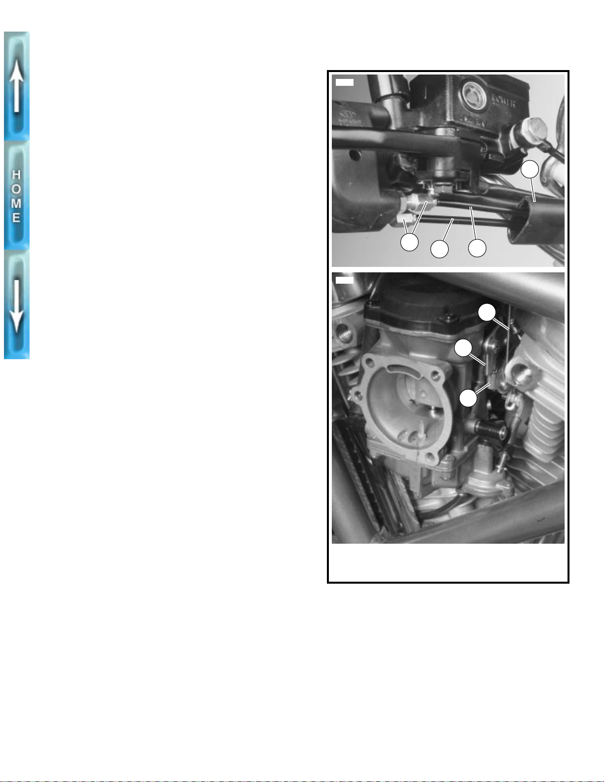
CARBURETOR
CABLE ADJUSTMENT
1WARNING
Throttle cables must not pull tight when handlebars are
turned fully to left or right fork stops. Be sure wires and
throttle cables are clear of fork stops at steering head so
they will not be pinched when fork is turned against stops.
Steering must be smooth and free with no binding or interference. Anything interfering with carburetor operation
may cause loss of vehicle control and per sonal injury.
Check throttle cable adjustment:
● Before every ride.
● At every scheduled service interval.
Check throttle cable adjustment with engine running. Turn
handlebars through full range of travel. If engine speed
changes during this maneuver, adjust throttle cables as follows:
1. Remove air cleaner. See AIR CLEANER, REMOVAL in
Section 4.
2. See Figure 1-41. Slide rubber boot (4) off cable
adjusters (3).
3. Loosen jam nut on each adjuster.
NOTE
Cable adjusters (3) and jam nuts are metric.
4. Turn adjusters in direction which will shorten cable housings to minimum length.
5. Point front wheel straight ahead. Twist throttle control grip
to fully open position; hold in position.
6. Turn adjuster (3) on throttle control cable (1) until throttle
cam stop (5) touches carburetor stop plate (6). Tighten
jam nut on throttle control cable (1) adjuster (3); release
throttle control grip.
7. Turn handlebars fully to right. Turn adjuster (3) on idle
control cable (2) until end of cable housing just touches
the carburetor cable guide.
8. Twist and release throttle control grip a few times. Carburetor throttle must return to idle position each time throttle grip is released. If this is not the case, turn adjuster (3)
on idle control cable (2) (shortening cable housing) until
throttle control functions properly.
9. Tighten jam nut on idle control cable (2) adjuster (3).
Recheck operation of throttle control (Step 7).
10. Slide rubber boot (4) over each cable adjuster (3).
Recheck engine slow idle speed; adjust if required.
11. Install air cleaner. See AIR CLEANER, INSTALLATION
in Section 4.
5587
3
5609
1. Throttle control cable
2. Idle control cable
3. Cable adjuster
Figure 1-41. Carburetor
2
1
1
6
5
4. Rubber boot
5. Throttle cam stop
6. Carburetor stop plate
4
IDLE ADJUSTMENT
Check idle adjustment:
● Before every ride.
● At every scheduled service interval.
See IGNITION TIMING on page 1-30.
1-29
Page 70
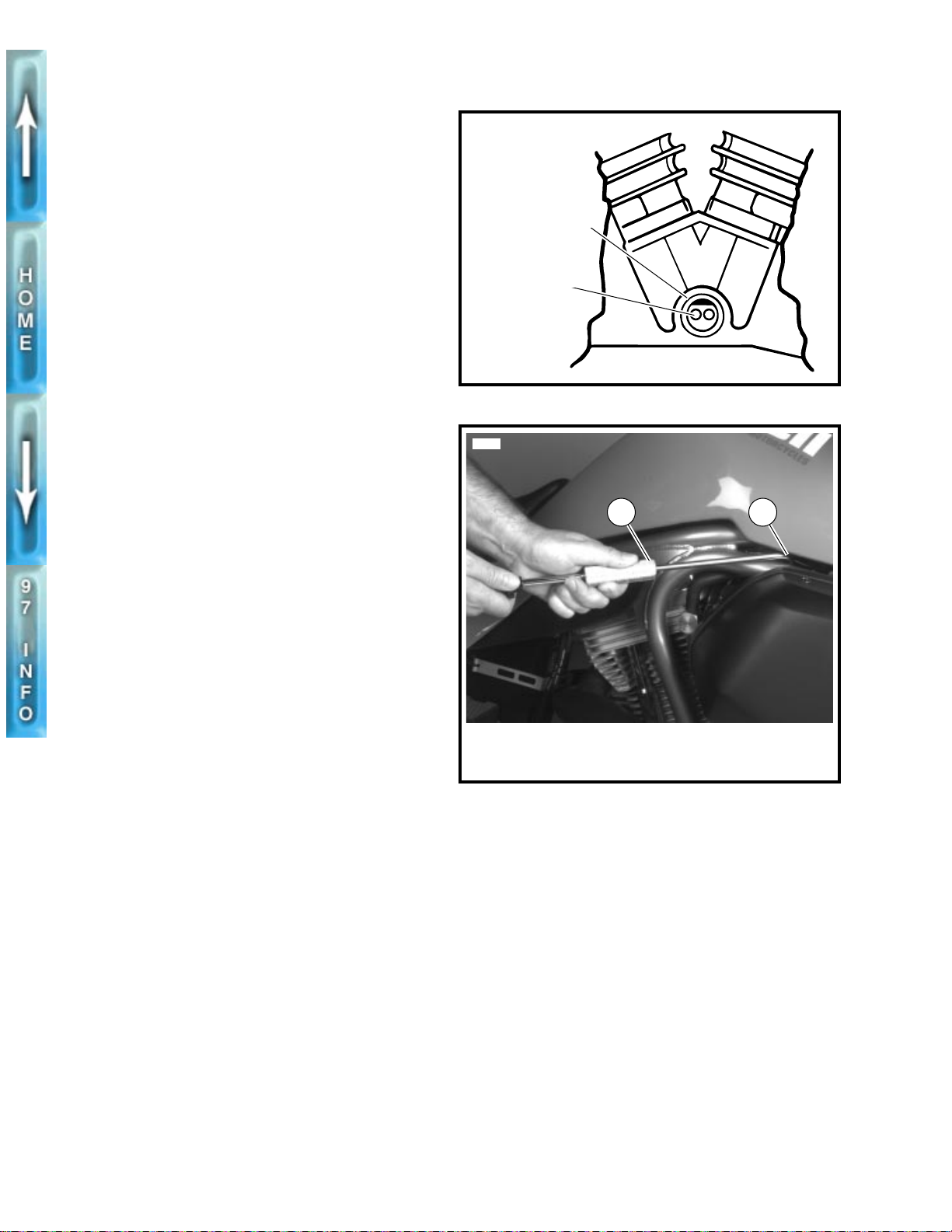
IGNITION TIMING
INSPECTION
Check ignition timing:
● At every 5000 mile (8000 km) service interval.
Check for proper RPM and ignition timing as follows:
1. See Figure 1-42. Thread TIMING MARK VIEW PLUG
(Part No. HD 96295-65D) into timing inspection hole. Be
sure view plug does not touch flywheel.
2. Connect leads of INDUCTIVE TIMING LIGHT (Part No.
HD-33813) to front spark plug cable, to battery positive
terminal and to ground.
3. Be sure vacuum hose is properly installed at carburetor
and at vacuum-operated electric switch (V.O.E.S.).
4. Start engine. Set engine speed by turning idle adjustment screw clockwise to increase speed or counterclockwise to decrease speed. Use CARBURETOR IDLE
ADJUSTMENT TOOL (Part No. HD-33413) and TIP
(SNAP-ON Part No. TMP23A) as shown in Figure 1-43.
a. On world models, idle speed is 950-1050 RPM.
b. On California models, idle speed is 1150-1250 RPM.
5. Timing light will flash each time ignition spark occurs.
Aim timing light into timing inspection hole. Front cylinder
advance timing mark should be centered in timing
inspection hole. If not, see ADJUSTMENT on page 1-31.
6. Set engine slow idle speed as described in Step 4 with
engine running at normal operating temperature and with
enrichener control knob pushed in fully.
NOTE
●
Buells have an enrichener circuit that will cause the
engine to idle at approximately 2000 RPM with the
engine at normal operating temperature and the
enrichener knob pulled out fully. The increase in idle
speed is intended to alert the rider that the engine is
warmed up to normal operating temperature and that the
enrichener knob should be pushed in all the way. Continuing to use the enrichener circuit when the engine is at
normal operating temperature will cause fouled plugs.
●
Be sure the engine is warmed up to normal operating
temperature and the enrichener knob is pushed all the
way in bef ore adjusting engine idle speed. Be aware that,
because there are variations in individual components, it
is possible for a properly warmed-up engine to idle at
2000 RPM with the enrichener knob pulled out partially.
x0001c2x
Inspection hole
Timing mark
Figure 1-42. Timing Inspection Hole
5599
1 2
1. Carburetor idle adjustment tool
(Part No. HD-33413)
2. Tip (Snap-On Part No. TMP23A)
Figure 1-43. Adjusting Idle Speed
1-30
Page 71
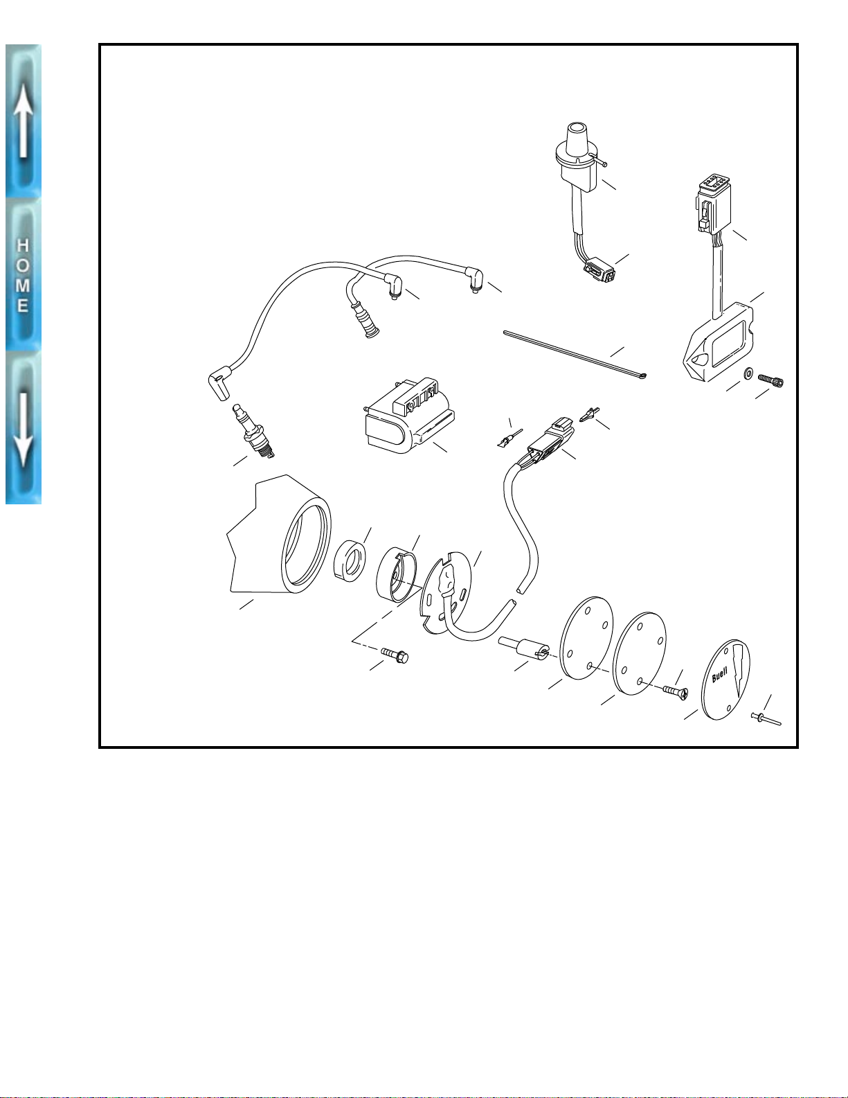
1. Pop rivet (2)
2. Timer cover
3. Screw (2)
4. Inner cover
5. Ignition gasket
6. Timer plate stud (2)
7. Bolt
8. Sensor assembly
9. Trigger rotor
10. Seal
11. Gearcase cover
12. Spark plug (2)
13. Ignition coil
14. Front spark plug cable
15. Rear spark plug cable
16. V.O.E.S. connector [P7]
17. V.O.E.S.
18. Cable strap
19. Terminal pin
20. Timer connector [P16]
21. Secondary lock
22. Ignition module connector [P10]
23. Ignition module
24. Washer (2)
25. Screw (2)
17
16
22
b0223x7x
12
11
15
14
18
23
24
19
25
21
10
13
9
20
8
3
7
6
1
5
4
2
Figure 1-44. Ignition System Components
ADJUSTMENT
1. See Figure 1-44. Remove outer cover pop rivets (1),
outer timer cover (2), inner cover screws (3), inner cover
(4) and gasket (5).
2. Loosen timer plate studs (6) just enough to allow sensor
assembly (8) to be rotated using a screwdriver in the
plate’s notch.
3. With timing light aimed into inspection hole, rotate sensor
assembly (8) until front cylinder advance timing mark is
centered in timing inspection hole.
4. Tighten timer plate studs (6).
5. Install gasket (5), inner cover (4), inner cover screws (3),
timer cover (2) and new outer cover rivets (1).
6. Remove TIMING MARK VIEW PLUG from timing inspection hole. Install hex socket timing plug.
1-31
Page 72
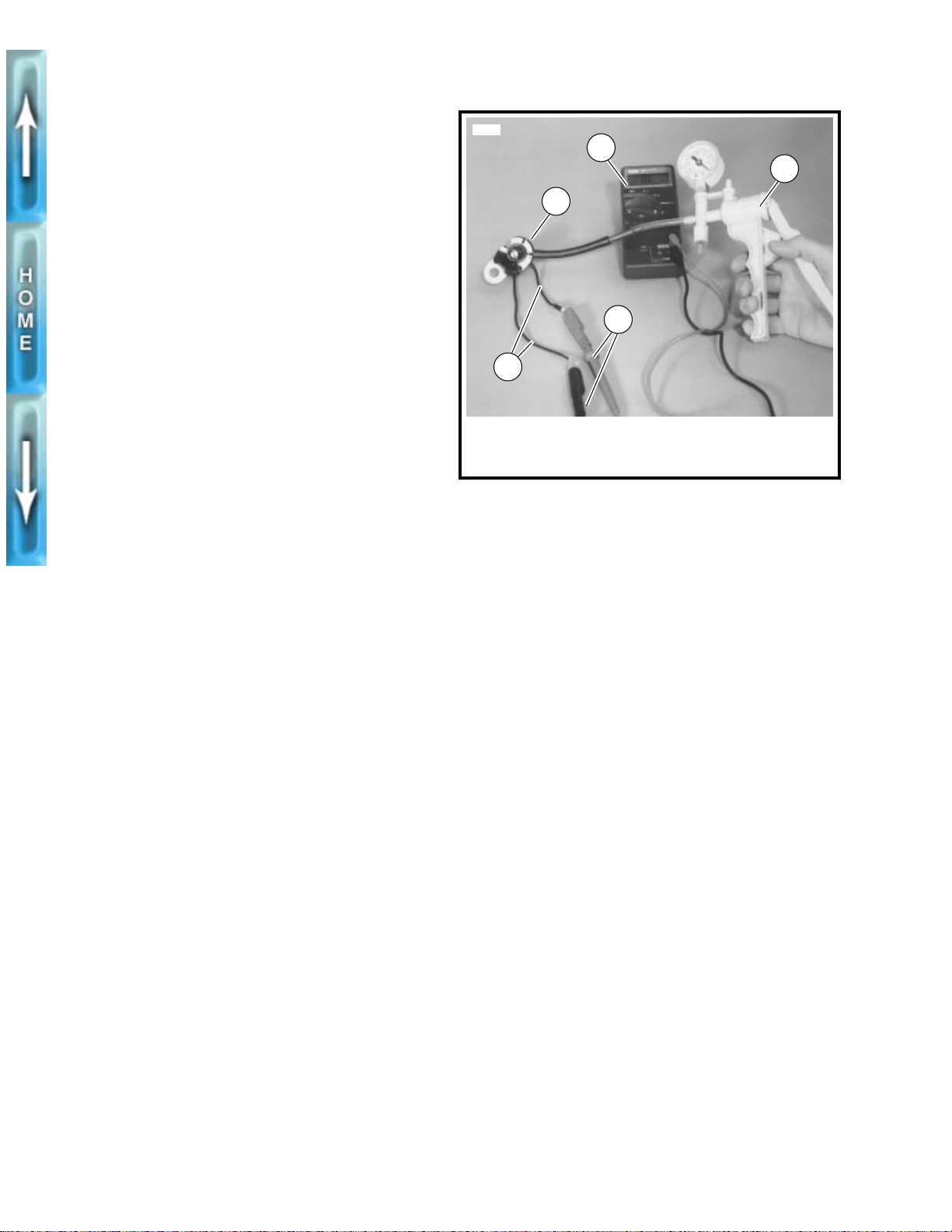
VACUUM-OPERATED ELECTRIC SWITCH (V.O.E.S)
ADJUSTMENT/TESTING
Timing Mark Method
Verify engine ignition timing. See IGNITION TIMING on
page 1-30. Adjust ignition timing, if necessary, and then per-
form the following V.O.E.S. check:
1. Run engine at regular idle. Disconnect V.O.E.S. vacuum
hose from carburetor fitting. See VACUUM-OPERATED
ELECTRIC SWITCH (V.O.E.S) in Section 7.
a. On world models, idle speed is 950-1050 RPM.
b. On California models, idle speed is 1150-1250 RPM.
2. Temporarily plug the open carburetor fitting. Ignition timing should retard (front cylinder advance timing mark disappears from view in timing inspection hole) and engine
RPM should decrease.
3. Connect V.O.E.S. vacuum hose to carburetor fitting. Timing mark should reappear and engine speed should
increase to previous RPM.
If speed does not first decrease and then increase as
described, check V.O.E.S. wire connection to ignition module.
2855
3
1
4
2
1. V .O .E.S.
2. V.O.E.S. leads
3. Ohmmeter
Figure 1-45. Checking V.O.E.S. Using Ohmmeter
and Vacuum Pump
4. Ohmmeter probes
5. Vacuum pump
5
Ohmmeter and Vacuum Pump Method
The V.O.E.S. can also be checked using an ohmmeter and a
VACUUM PUMP (Part No. HD-23738).
1. Remove V.O.E.S. from vehicle. See VACUUM-OPER-
ATED ELECTRIC SWITCH (V.O.E.S) in Section 7.
2. See Figure 1-45. Connect two ohmmeter leads to the two
V.O.E.S. leads.
3. Connect vacuum pump to V.O.E.S. vacuum fitting.
4. Slowly squeeze vacuum pump handle. Obser ve vacuum
gauge and ohmmeter readings. Ohmmeter should indicate switch closed (zero ohms) with an applied vacuum
of 5.0-6.0 in. (127.0-152.4 mm) mercury (Hg). If a vacuum reading of more than 6.0 in. (152.4 mm) Hg or less
than 5.0 in. (127.0 mm) Hg is required to close the
switch, then the switch must be replaced.
5. Install V.O.E.S. See VACUUM-OPERATED ELECTRIC
SWITCH (V.O.E.S) in Section 7.
1-32
Page 73
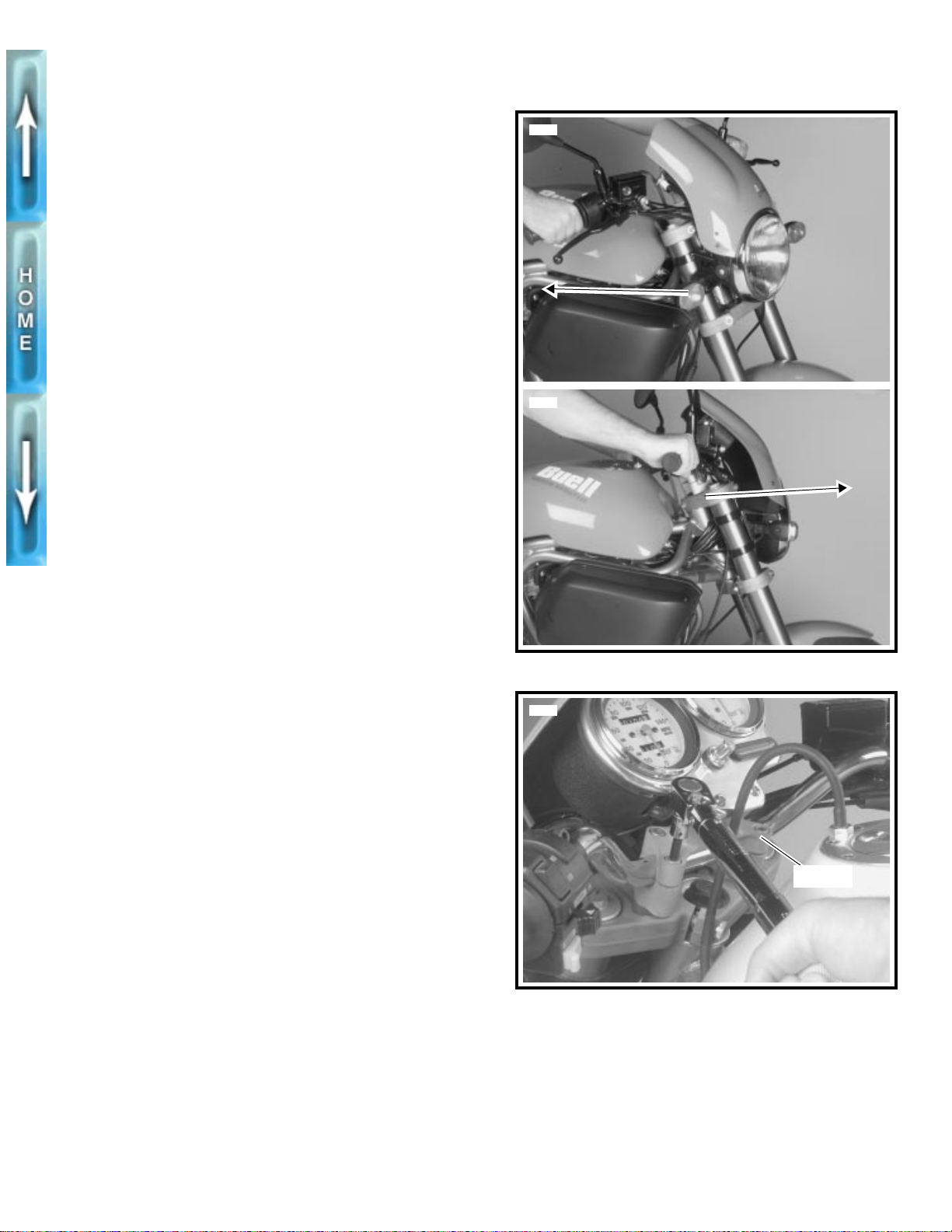
HANDLEBARS
INSPECTION
Check handlebar adjustment:
● Before every ride.
1. See Figure 1-46. Check steering motion range to both
fork stops. Each handlebar should be spaced equally
between the windscreen and fuel tank and parts should
not make contact.
2. Handlebars should be equally spaced between outside
edge of handlebar clamp and inside edge of mirror
mounts.
If necessary, adjust handlebars as described below.
ADJUSTMENT
CAUTION
1
Never adjust handlebars using excessive force or damage to handlebars might result.
NOTE
5589
5590
Windscreen and instrument support must be removed to
access front clamp screws.
1. Remove windscreen. See WINDSCREEN in Section 2.
2. Remove instrument support. See SPEEDOMETER AND
TACHOMETER in Section 2.
3. See Figure 1-47. Loosen clamp screws.
4. Move handlebar to desired position.
5. Tighten clamp screws to 10-12 ft-lbs (13.6-16.2 Nm).
NOTE
Tighten front clamp screws first.
6. Install instrument support. See SPEEDOMETER AND
TACHOMETER in Section 2.
7. Install windscreen. See WINDSCREEN in Section 2.
8. Check steering motion range to both fork stops. Each
handlebar should be spaced equally between windscreen and fuel tank and parts should not make contact.
If handlebar needs further adjustment, repeat ADJUST-
MENT beginning with Step 1.
Figure 1-46. Testing Handlebars
5576
Clamp
Figure 1-47. Adjusting Handlebars
1-33
Page 74
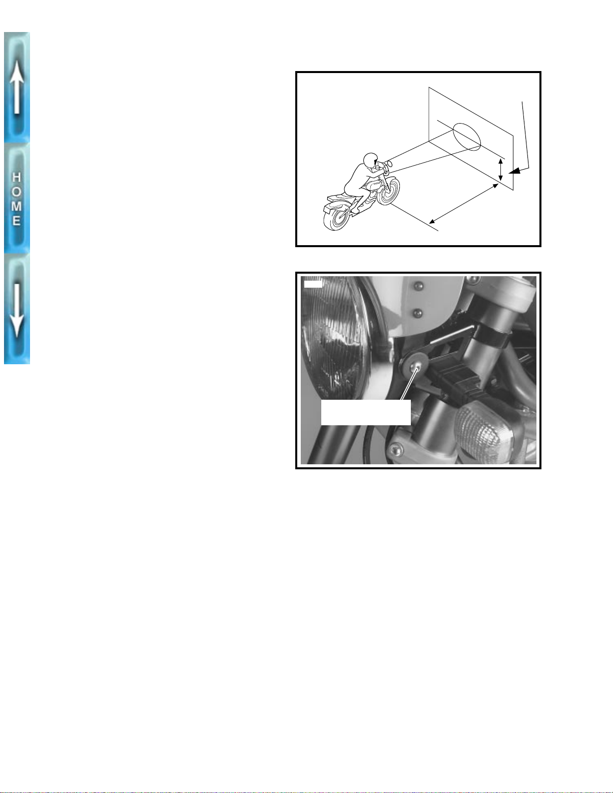
HEADLAMP
INSPECTION
1WARNING
Do not modify ignition wiring to permit motorcycle operation with headlamp off. Operating with headlamp off may
reduce your visibility to other motorists and could cause
an accident resulting in personal injury.
Check headlamp alignment:
● When a new rider buys the motorcycle.
● When there is a change in load (luggage, etc.)
Check headlamp beam for proper height and lateral alignment as follows:
1. Verify correct front and rear tire inflation pressure. See
TIRES AND WHEELS on page 1-18.
2. Place motorcycle on level floor (or pavement) in an area
with minimum light.
3. See Figure 1-48. Point front of motorcycle toward a
screen or wall which is 25 ft (7.62 M) away from front tire
contact patch on floor (i.e., directly below front axle).
4. Draw a horizontal line, on screen or wall, which is 35 in.
(889 mm) above floor.
b0008b7x
Figure 1-48. Checking Headlamp Alignment
5601
35 in.
(889 mm)
25 ft
(7.62 M)
5. Have a person whose weight is roughly the same as that
of the principal rider sit on motorcycle seat. Weight of
rider will compress vehicle suspension slightly.
6. Stand motorcycle upright with both tires resting on floor
and with front wheel held in straight alignment (directly
forward).
7. Turn ignition switch to IGN. Set handlebar headlamp
switch to HIGH beam position.
8. Check light beam for proper height alignment. Main
beam of light (broad, flat pattern of light) should be centered on horizontal line on screen or wall (i.e. equal area
of light above and below line).
9. Check light beam for proper lateral alignment. Main
beam of light should be directed straight ahead (i.e.
equal area of light to right and left of center).
ADJUSTMENT
If headlamp requires adjustment, perform the following:
1. See Figure 1-49. Loosen both adjuster screws (metric).
2. See Figure 1-48. Tilt headlamp up or down to aim it in
relation to the horizontal line. At the same time, turn
headlamp right or left to direct light beam straight ahead.
Headlamp adjuster
screw (metric)
Figure 1-49. Adjusting Headlamp
3. Tighten both adjuster screws (metric) to 6-8 ft-lbs (8.1-
10.8 Nm).
1-34
Page 75
STORAGE
GENERAL
If the motorcycle will not be operated for sev er al months , such
as during the winter season, there are several things which
should be done to protect parts against corrosion, to preserve
the battery and to prevent the buildup of gum and varnish in
the carburetor.
This work should be performed by your local Buell dealer
following Service Manual procedures.
1WARNING
Gasoline is flammable. Do not store motorcycle having
gasoline in tank within the home or garage where open
flames, pilot lights, sparks or electric motors are present.
Inadequate safety precautions may cause an accident
resulting in personal injury.
1. Fill fuel tank and add a gasoline stabilizer. Use one of
the commercially available gasoline stabilizers following
the manufacturer’s instructions. Run engine until
gasoline has had a chance to reach carburetor float
bowl. Turn fuel supply valve OFF.
2. Fill the oil tank. Pinch off (or remove and plug) the line
leading from the oil tank bottom to the oil pump feed
fitting. This prevents oil from seeping past the check ball
into the oil pump and filling the engine flywheel
compartment.
3. Remove the spark plugs, inject a few squirts of engine oil
into each cylinder and crank the engine 5-6 revolutions.
Reinstall spark plugs.
4. Adjust primary chain.
5. Adjust secondary drive belt.
6. Check tire inflation. If the motorcycle will be stored for an
extended period of time, securely support the motorcycle
under the frame so that all weight is off the tires.
1WARNING
Do not apply any oil to brake rotors or brake pads. Oil on
brake pads degrades braking efficiency and can result in
an accident causing personal injury.
7. Wash painted and chrome-plated surfaces. Apply a light
film of oil to exposed unpainted surfaces.
8. If motorcycle is to be covered, use a material that will
breathe, such as light canvas. Plastic materials that do
not breathe promote the formation of condensation.
REMOVAL FROM STORAGE
1
WARNING
After extended periods of storage and prior to starting
vehicle, place transmission in gear, disengage clutch and
push vehicle back and forth a few times to ensure proper
clutch disengagement. Improper clutch disengagement
could result in personal injury.
1. Remove and inspect spark plugs. Replace if necessary.
2. Clean air filter element and lubricate if necessary.
3. If fuel tank was drained, fill fuel tank with fresh gasoline.
4. If oil feed line was pinched off or plugged, unplug it and
reconnect.
5. Start the engine and run until it reaches normal operating
temperature. Check fluids and refill to proper levels if
required.
a. Check engine oil level.
b. Check the transmission lubricant level.
6. Perform all of the checks in the PRE-RIDING CHECK
LIST in the Owner’s Manual.
1-35
Page 76
TROUBLESHOOTING
GENERAL
The following check list can be helpful in locating most
operating troubles. Refer to the appropriate sections in this
Service Manual for detailed procedures.
ENGINE
Starter Motor Does Not Operate or Does
Not Turn Engine Over
1. Engine stop switch in OFF position.
2. Ignition key switch not ON.
3. Discharged battery or loose or corroded connections.
(Solenoid chatters.)
4. Starter control relay or solenoid not functioning.
5. Electric starter shaft pinion gear not engaging or overrunning clutch slipping.
Engine Turns Over But Does Not Start
1. Fuel tank empty.
2. Fuel supply valve turned OFF.
3. Fuel supply valve or filter clogged.
4. Discharged battery, loose or broken battery terminal
connections.
5. Fouled spark plugs.
6. Loose or shorting spark plug cables or connections.
7. Ignition timing badly out of adjustment.
8. Loose wire connection at coil or battery connection or
plug between ignition sensor and module.
9. Ignition coil not functioning.
10. Ignition module not functioning.
11. Ignition sensor not functioning.
12. Sticking or damaged valve or valves.
13. Engine flooded with gasoline as a result of overchoking.
14. Engine oil too heavy (winter operation).
Starts Hard
1. Spark plugs in bad condition, have improper gap or are
partially fouled.
2. Spark plug cables in bad condition and shorting.
3. Battery nearly discharged.
4. Loose wire connection at one of the battery terminals, at
coil or at plug between ignition sensor and module.
5. Carburetor controls not adjusted correctly.
6. Ignition coil not functioning.
7. Engine oil too heavy (winter operation).
8. Ignition not timed properly. See dealer.
9. Vapor vent valve plugged or carburetor fuel line closed
off restricting fuel flow.
10. Water or dirt in fuel system and carburetor.
11. Enrichener valve inoperative.
12. Air leak at intake manifold.
13. Valves sticking.
Starts But Runs Irregularly or Misses
1. Spark plugs in bad condition or partially fouled.
2. Spark plug cables in bad condition and shorting.
3. Spark plug gap too close or too wide.
4. Ignition coil not functioning.
5. Ignition module not functioning.
6. Ignition sensor not functioning.
7. Battery nearly discharged.
8. Damaged wire or loose connection at battery terminals
or coil.
9. Intermittent short circuit due to damaged wire insulation.
10. Water or dirt in fuel system and carburetor or filter.
11. Fuel tank filler cap vent plugged or carburetor float bowl
vent closed off.
12. Carburetor controls improperly adjusted.
13. Air leak at intake manifold or air filter.
14. Damaged intake or exhaust valve.
15. Weak or broken valve springs.
16. Incorrect valve timing.
Spark Plug Fouls Repeatedly
1. Incorrect spark plug.
2. Piston rings badly worn or broken.
3. Fuel mixture too rich for conditions (see CARBURETOR
TROUBLESHOOTING).
4. Valve stem seals worn or damaged.
5. Valve guides badly worn.
Pre-Ignition or Detonation (Knocks or Pings)
1. Excessive carbon deposit on piston head or combustion
chamber.
2. Incorrect heat range spark plug.
3. Spark plugs not firing.
4. Ignition timing advanced.
5. Fuel octane rating too low.
6. Intake manifold vacuum leak.
Overheating
1. Insufficient oil supply or oil not circulating.
2. Leaking valves.
3. Heavy carbon deposit.
4. Ignition timing retarded.
Valve T rain Noise
1. Hydraulic lifter not functioning properly.
2. Bent push rod.
3. Cam, cam gears or cam bushings worn.
4. Rocker arm binding on shaft.
5. Valve sticking in guide.
1-36
Page 77
Excessive Vibration
FUEL
1. Engine tie-bars loose, broken or improperly spaced.
2. Lower mounting bolts loose.
3. Broken frame.
4. Primary chain badly worn or links tight as a result of
insufficient lubrication.
5. Wheels not aligned and/or tires worn.
6. Internal engine problem.
ENGINE LUBRICATION SYSTEM
Oil Does Not Return To Oil Tank
1. Oil tank empty.
2. Return pump gears damaged.
3. Oil feed pump not functioning.
4. Restricted oil lines or fittings.
Engine Uses Too Much Oil or Smokes Excessively
1. Piston rings badly worn or broken.
2. Valve stem seals worn or damaged.
3. Valve guides worn.
Carburetor Floods
1. Excessive “pumping” of throttle control grip.
2. Inlet valve sticking.
3. Inlet valve and/or valve seat worn or damaged.
4. Dirt or other foreign matter between valve and its seat.
5. Float misadjusted or filled with fuel.
TRANSMISSION
Shifts Hard
1. Clutch dragging slightly.
2. Shifter forks (inside transmission) damaged.
3. Corners worn off shifter clutch dogs (inside
transmission).
Jumps Out of Gear
1. Shifter pawl improperly adjusted.
2. Shifter engaging parts (inside transmission) badly worn
and rounded.
3. Shifter forks bent.
4. Damaged gears.
Engine Leaks Oil From Cases, Push Rods,
Hoses, Etc.
1. Loose parts.
2. Imperfect seal at gaskets, push rod cover, washers, etc.
To aid locating leaks, use BLACK LIGHT LEAK
DETECTOR (Part No. HD-35457).
3. Restricted oil return line to tank.
4. Restricted breather passage(s) to air cleaner.
ELECTRICAL SYSTEM
Alternator Does Not Charge
1. Regulator-rectifier module not functioning.
2. Rectifier not grounded.
3. Engine ground wire loose or broken.
4. Loose or broken wires in charging circuit.
5. Stator not functioning.
6. Rotor not functioning.
Alternator Charge Rate Is Below Normal
1. Regulator-rectifier module not functioning.
2. Stator not functioning.
3. Rotor not functioning.
4. Weak battery.
5. Loose connections.
CLUTCH
Slips
1. Clutch controls improperly adjusted.
2. Worn friction plates.
Drags or Does Not Release
1. Clutch controls improperly adjusted.
2. Clutch plates excessively warped.
Chatters
1. Friction or steel plates worn, warped or dragging.
CHASSIS
Irregular/Inadequate Brake Action
1. Master cylinder low on fluid.
2. Brake line contains air bubbles.
3. Master or wheel cylinder piston worn.
4. Brake pads covered with grease or oil.
5. Brake pads badly worn (1/16 in. (1.6 mm) minim um lining
thickness).
6. Brake rotor badly worn or warped.
7. Brake pads dragging or excessive braking (brake fades
due to heat buildup).
8. Insufficient brake pedal or hand lever freeplay (brake
drags).
1-37
Page 78
Handling Irregularities
1. Tires improperly inflated. Check TIRES AND WHEELS
on page 1-18. Do not overinflate.
2. Loose wheel axle nuts. Tighten front nut to 48-53 ft-lbs
(65.1-71.9 Nm). Tighten rear nut to 66-73 ft-lbs (90-99
Nm).
3. Excessive wheel hub bearing play.
4. Rear wheel out of alignment with frame and front wheel.
5. Rims and tires out-of-true sideways (tire runout should
not be more than 0.080 in. (2.03 mm)).
6. Rims and tires out-of-round or eccentric with hub (tire
runout should not be more than 0.090 in. (2.29 mm)).
7. Irregular or peaked front tire tread wear.
8. Tire and wheel unbalanced.
9. Steering head bearings improperly adjusted. Correct
adjustment and replace pitted or worn bearings and
races. See FORK STEM AND BRACKET ASSEMBLY in
Section 2.
10. Shock absorber not functioning normally.
11. Heavy front end loading. Non-standard equipment on the
front end (such as heavy radio receivers, extra lighting
equipment or luggage) tends to cause unstable handling.
1-38
Page 79
2
SPECIFICATIONS
DIMENSIONS IN. MM
Wheel Base 55 1397
Overall Length 79.5 2019
Overall Width 30 762
Seat Height 29.5 749
CHASSIS IN. MM
Road Clearance 5.2 132
Front Wheel Travel 4.7 119.4
Rear Wheel Travel 4.9 124.5
Trail 3.9 99
Rake 25 degrees
WEIGHT LBS. KG
S1 Shipping weight 446 202
GVWR 820 372
GAWR - Front 340 154
GAWR - Rear 480 218
NOTE
Gross Vehicle Weight Rating (GVWR) (maximum allowable
loaded vehicle weight) and corresponding Gross Axle Weight
Ratings (GAWR) are giv en on an inf ormation decal located on
the front frame steering head.
CAPACITIES U.S. LITERS
Fuel Tank (including reserve) 4.0 gallons 15.14
Reserve 0.6 gallons 2.27
Oil T ank 2.0 quarts 1.89
Transmission 1.0 quart 0.95
PRESSURE
TIRE AND POSITION
Front-Dunlop Sportmax
Radial II 120/70 ZR 17
Rear-Dunlop Sportmax
Radial II 170/60 ZR 17
1
Do not inflate any tire beyond its maxim um inflation pressure as specified on tire sidewall. Overinflation may
cause tire to suddenly deflate leading to personal injury.
BRAKE ROTORS IN. MM
Front rotor minimum thickness 0.17 4.3
Rear rotor minimum thickness 0.19 4.8
FOR SOLO
RIDING
32 PSI
(2.2 bar)
36 PSI
(2.5 bar)
WARNING
PRESSURE
AT GVWR
36 PSI
(2.5 bar)
38 PSI
(2.8 bar)
2-1
Page 80
ITEM TORQUE NOTES
Clutch cable, primary
cover fitting
Clutch clamp screw 30-33
Drive support fastener 30-35 ft-lbs 40.7-47.4 Nm page 2-53
Exhaust manifold nuts 6-8 ft-lbs 8.1-10.8 Nm page 2-50
Fender mounting screw, lower 10-15
Fender mounting screw, upper 20-25
Front axle nut 48-53 ft-lbs 65.1-71.9 Nm
Front axle pinch screw 13-15 ft-lbs 17.6-20.3 Nm metric, page 2-10
Front brake caliper screw 26-28 ft-lbs 35.2-38.0 Nm 2 sizes, page 2-21
Front brake carrier screw 7.5-8.5 ft-lbs 10.2-11.5 Nm LOCTITE THREADLOCKER 242 (blue), page 2-9
Front brake line clamp screw 30-35
Front brake master cylinder
clamp screw
Front brake rotor carrier screw 20-22 ft-lbs 27.1-29.8 Nm LOCTITE THREADLOCKER 242 (blue), page 2-9
Front caliper banjo bolt 16-20 ft-lbs 21.7-27.1 Nm page 2-21, page 2-22
Front caliper bleeder valve 4-6 ft-lbs 5.4-8.1 Nm page 2-22
3-5 ft-lbs 4-6.87 Nm turn clockwise to install, page 2-45
80-90
in-lbs
in-lbs
in-lbs
in-lbs
in-lbs
3.4-4.0 Nm metric, page 2-45
1.1-1.7 Nm page 2-54
2.3-2.8 Nm metric, page 2-54
LOCTITE THREADLOCKER 242 (blue), metric,
page 2-6, page 2-10
3.4-4.0 Nm page 2-22
9.0-10.2 Nm metric, page 2-19
Front caliper center bolt 11-13 ft-lbs 14.9-17.6 Nm page 2-21
Front caliper mounting bolt 30-33 ft-lbs 40.7-44.7 Nm page 2-21
Front fork triple clamp screw 18-20 ft-lbs 24.4-27.1 Nm LOCTITE ANTI-SEIZE, page 2-31
Front master cylinder
banjo bolt
Front master cylinder
cover screw
Fuel tank screw 9-11 ft-lbs 12.2-14.9 Nm page 2-55
Handlebar bolt, lower clamp 30-33 ft-lbs 40.7-44.7 Nm page 2-49
Handlebar screw, upper clamp 10-12 ft-lbs 13.6-16.2 Nm page 2-49
Header tiebar screw 5-7 ft-lbs 6.8-9.5 Nm page 2-50
Headlamp adjusting screw 6-8 ft-lbs 8.1-10.8 Nm metric, page 2-56
Instrument support screw 7-9 ft-lbs 9.5-12.2 Nm page 2-46
Muffler clamp 50-55 ft-lbs 67.8-74.6 Nm discard after use, page 2-50
Muffler mounting bolt, front 22-25 ft-lbs 29.8-33.9 Nm page 2-50
Muffler mounting bolt, rear 22-25 ft-lbs 29.8-33.9 Nm page 2-50
Muffler support mounting
bolt, front
17-20 ft-lbs 23.0-27.1 Nm metric, page 2-19, page 2-22
9-13
in-lbs
30-33 ft-lbs 40.7-44.7 Nm page 2-50
1.0-1.5 Nm page 2-19, page 2-21
Muffler support mounting
bolt, rear
2-2
12-15 ft-lbs 16.3-20.3 Nm page 2-50
Page 81
ITEM TORQUE NOTES
Rear axle nut 66-73 ft-lbs 89.5-98.9 Nm metric, page 2-6, page 2-13
Rear brake caliper banjo bolt 9.5-12.5 ft-lbs 12.9-17.0 Nm metric, page 2-26, page 2-27
Rear brake caliper
bleeder valve
Rear brake caliper
mounting screw
Rear brake lamp switch 7-8 ft-lbs 9.5-10.8 Nm LOCTITE SEALANT WITH TEFLON, page 2-27
Rear brake line clamp screw 10-12 ft-lbs 13.6-16.2 Nm page 2-27
Rear brake reservoir
mounting screw
Rear brake rotor screw 35-40 ft-lbs 47.5-54.2 Nm
Rear master cylinder banjo bolt 10-12 ft-lbs 13.6-16.2 Nm metric, page 2-24, page 2-27
Rear master cylinder
mounting screw
Rear master cylinder rod to
brake pedal screw
Rear shock mounting screw 40-45 ft-lbs 54.2-61.0 Nm metric, page 2-37
Sprocket bolt 55-65 ft-lbs 74.6-88.1 Nm LOCTITE THREADLOCKER 272 (red), page 2-12
Sprocket cover mounting screw 12-17
Sprocket cover screw 4-6 ft-lbs 5.4-8.6 Nm page 2-53
6-9 ft-lbs 8.1-12.2 Nm metric, page 2-26, page 2-27
18-22 ft-lbs 24.4-29.8 Nm metric, page 2-26
12-15
in-lbs
8-10 ft-lbs 10.8-13.6 Nm page 2-24
10-12 ft-lbs 13.6-16.2 Nm page 2-24
in-lbs
1.4-1.7 Nm page 2-24
LOCTITE THREADLOCKER 242 (blue), metric,
page 2-12
1.4-1.9 Nm page 2-53
Swingarm pinch screw 27-30 ft-lbs 36.6-40.7 Nm LOCTITE THREADLOCKER 242 (blue), page 2-34
Swingarm/drive support screw 20-25 ft-lbs 27.1-33.9 Nm page 2-53
Switchgear housing screws,
left side
Switchgear housing screws,
right side
Tie bar bolt 30-33 ft-lbs 40.7-44.7 Nm page 2-34
Valve stem nut 42-44
25-33
12-17
in-lbs
in-lbs
in-lbs
2.8-3.7 Nm metric, page 2-45
1.4-1.9 Nm metric, page 2-43
4.7-5.0 Nm page 2-16
2-3
Page 82
TIRE SPECIFICATIONS
GENERAL
1
WARNING
Tires must be correctly matched to wheel rims. Only the
tires listed in the fitment tables below can be used for
replacement. Mismatching tires and rims can cause damage to the tire bead during mounting. Using tires other
than those specified can adversely affect motorcycle
handling and may result in personal injury.
Tire sizes are molded on the sidewall. Rim size and contour
are marked on the rim’s exterior surface.
Example:
MT
bead seat measured in inches. The
ter of the rim in inches, measured at the bead seat diameter.
DOT
Federal Motor Vehicle Safety Standards.
See the tables below.
MT 3.5 x 17.0 DOT
designates the rim contour. The
means that the rim meets Department of Transportation
Table 2-1. Tire Fitment – Tubeless Cast Marchesini Wheels
WHEEL SIZE
& POSITION
17 in. – Front MT 3.5 x 17.0 DOT 0.33 in. 120/70 ZR17
17 in. – Rear MT 5.0 x 17.0 DOT 0.33 in. 170/60 ZR17
CONTOUR &
RIM SIZE
RIM V AL VE
HOLE DIAMETER
DUNLOP SPORTMAX RADIAL II
Table 2-2. Tire Fitment – Tubeless Aluminum P/M Wheels
3.5
is the width of the
17.0
is the normal diame-
TIRE SIZE
WHEEL SIZE
& POSITION
17 in. – Front MT 3.5 x 17.0 DOT 0.33 in. 120/70 ZR17
17 in. – Rear MT 5.5 x 17.0 DOT 0.33 in. 170/60 ZR17
CONTOUR &
RIM SIZE
RIM V AL VE
HOLE DIAMETER
DUNLOP SPORTMAX RADIAL II
TIRE SIZE
2-4
Page 83
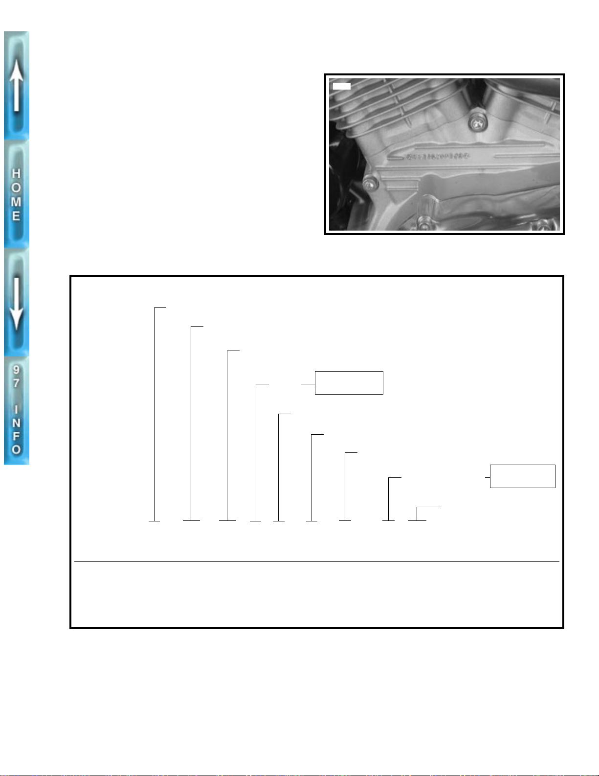
VEHICLE IDENTIFICATION NUMBER
GENERAL
A 17-digit serial number, or Vehicle Identification Number
(V.I.N.), is stamped on the right side of the steering head (ex.,
4MZSS11J1T3200001). Also affixed to the steering head at
this location is an information plate bearing the V.I.N. code.
See Figure 2-1. An abbreviated V.I.N. is stamped on the front
left side of the crankcase.
NOTE
Always give the V.I.N. or abbreviated V.I.N. when ordering
parts or making inquiries about your Buell motorcycle.
Motorcycle Made in U.S.A.
Manufacturer and Make: Buell Motorcycle Company
Model Designation: SS = S1 Lightning
5711
Figure 2-1. Abbreviated V.I.N. Location
Engine
4MZSS 11 J*T320 0001
*Varies - can be 0 through 9 or X
Sample V.I.N. as it appears on the steering head - 4MZSS11J1T3200001
Sample abbreviated V.I.N. as it appears on the left side crankcase- SS11T200001
Two market destination characters have been used beginning with sequential number 38.
Figure 2-2. Vehicle Identification Number (V.I.N.)
11 = 49 state
56 = California
Horsepower Code
Factory Check Digit: Can be 0-9 or x
Year of Manufacture: T = 1996
Market Designation
NOTE
See Note
Sequential Number
20 = World
22 = California
2-5
Page 84
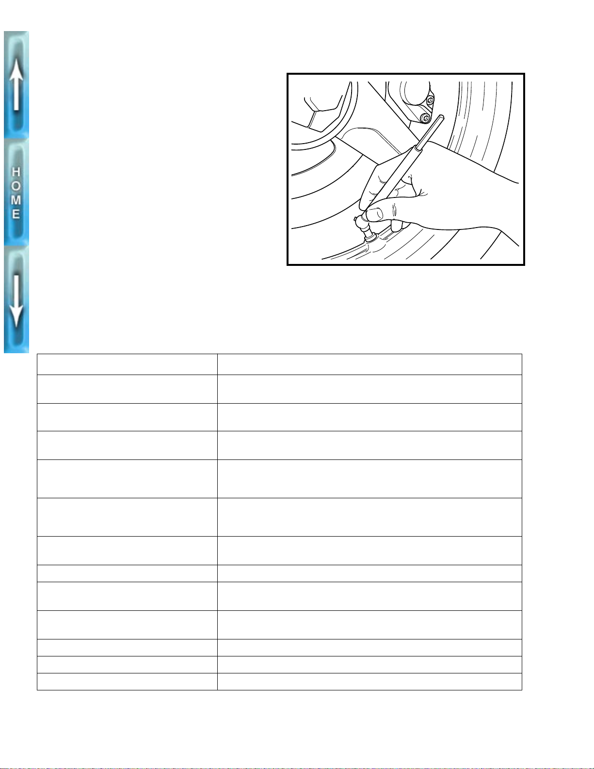
WHEELS
GENERAL
Good handling and maximum tire mileage are directly related
to the care of wheels and tires. Regularly inspect wheels and
tires for damage and wear. If handling problems occur, check
the TROUBLESHOOTING guide in Section 1 or see the table
below for a list of probable causes.
See TIRES AND WHEELS in Section 1. Keep tires inflated to
the recommended air pressure. Always balance the wheel
after replacing a tire.
1
WARNING
Do not inflate any tire beyond its maxim um inflation pressure as specified on tire sidewall. Overinflation may
cause tire to suddenly deflate leading to personal injury.
TROUBLESHOOTING
See Figure 2-3. Check tire inflation pressure at least once
each week. At the same time, inspect tire tread for punctures,
cuts, breaks and other damage. Repeat the inspection before
long trips.
Table 2-3. Wheel Service
b0195x2x
Figure 2-3. Checking Tire Inflation Pressure
CHECK FOR REMEDY
1. Loose axle nuts. Tighten front axle nut (metric) to 48-53 ft-lbs (65.1-71.9 Nm). Tighten rear
axle nut (metric) to 66-73 ft-lbs (89.5-98.9 Nm).
2. Excessive side-play or radial (up-and-
down) play in wheel hubs.
3. Alignment of rear wheel in frame or
with front wheel.
4. Rims and tires out-of-true sideways;
should not be more than 0.080 in.
(2.03 mm).
5. Rims and tires out-of-round or eccen-
tric with hub; should not be more than
0.090 in. (2.29 mm).
6. Irregular or peaked front tire wear. Replace as described under FRONT WHEEL (page 2-8), REAR WHEEL
7. Correct tire inflation. Inflate tires to correct pressure. See SPECIFICATIONS on page 2-1.
8. Correct tire and wheel balance. Static balance may be satisfactory if dynamic balancing facilities are not
9. Steering head bearings. Correct adjustment and replace pitted or worn bearings. See FORK STEM
Replace wheel hub bearings.
Check WHEEL BALANCING on page 2-17 or repair swingarm as described
under SWINGARM on page 2-33.
Replace rims. See TIRES, INSTALLATION on page 2-16.
See Item 4 above.
(page 2-11) and TIRES (page 2-15).
available. However, dynamic balancing is strongly recommended.
AND BRACKET ASSEMBLY on page 2-32.
10. Damper tubes. Check for leaks. See FRONT FORK on page 2-28.
11. Shock absorbers. Check damping action and mounts. See SWINGARM on page 2-33.
12. Swingarm bearings. Check for looseness. See SWINGARM on page 2-33.
2-6
Page 85
1
WARNING
To prevent personal injury, use the following guidelines
when installing a new tire or repairing a flat:
1. Always locate and eliminate the cause of the original
tire failure.
2. Do not patch or vulcanize a tire casing. These proce-
dures weaken the casing and increase the risk of a
blowout.
3. The use of tires other than those specified can
adversely affect handling resulting in personal injury.
4. Tires and wheels are critical safety items. Since the
servicing of these components requires special
tools and skills, Buell recommends that you see your
dealer for these services.
1
WARNING
Excessively worn tires adversely affect motorcycle traction, steering and handling and could result in personal
injury.
At regular intervals of 5000 miles (8000 km) or whenever handling irregularities are noted, perform the recommended service checks. See Table 2-3.
If tires must be replaced, same as original equipment tires
must be used. Other tires may not fit correctly and may be
hazardous to use.
2-7
Page 86
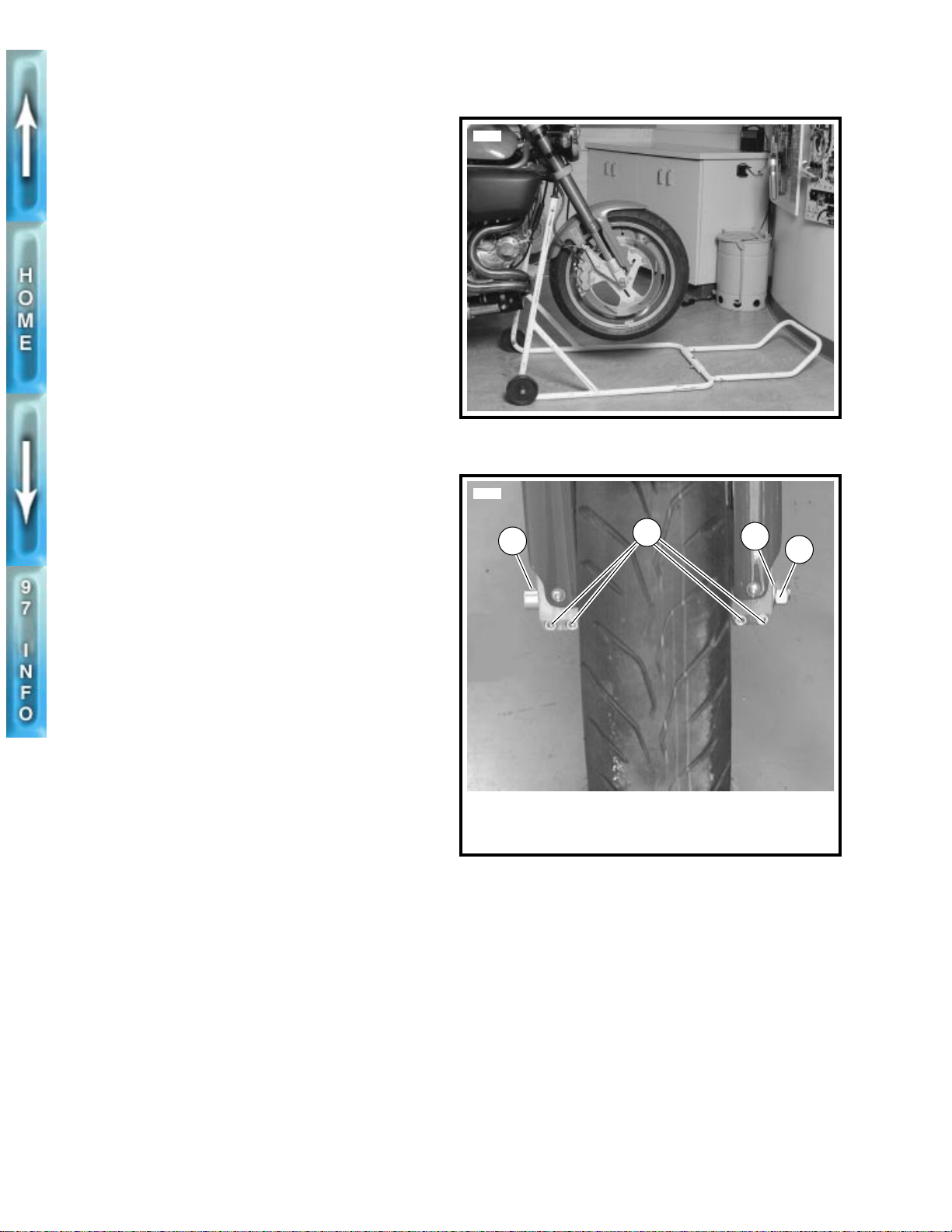
FRONT WHEEL
REMO V AL
1. See Figure 2-4. Raise front wheel off floor using FRONT
WHEEL SUPPORT STAND (Part No. B-41395) and S1
LIFT ADAPTER (Part No. B-41686).
2. Remove front brake caliper. See FRONT BRAKE CALI-
PER, REMOVAL/DISASSEMBLY on page 2-20.
NOTE
Do not operate front brake lever with front wheel removed or
caliper pistons may be forced out. Reseating pistons requires
caliper disassembly.
3. See Figure 2-5. Insert screwdriver/rod through hole in
axle (1) and loosen front axle nut (4) (metric).
4. Loosen pinch screws (2) (metric).
5. Remove front axle nut (4) and washer (3). Pull front axle
out of hub while supporting front wheel.
6. See Figure 2-6. Detach speedometer drive spacer (3)
and speedometer drive (4) from left side of wheel.
Remove front wheel.
DISASSEMBLY
1. See Figure 2-6. Move wheel to bench area. On the side
of the wheel opposite the brake rotor, remove left axle
spacer (5).
2. On brake rotor side of wheel, remove right axle
spacer (12).
3. Remove wheel bearings (6, 11) using BUSHING AND
BEARING PULLER (Part No. HD-95760-69A) and 3/4 in.
COLLET (Part No. HD-95767-69A).
4. Remove six locknuts (14), washers (21), spring washers
(20), screws (19) and brake drive pins (18). Remove
brake rotor (17).
5. Remove five screws (16) and front brake carrier (15).
6. Remove tire. See TIRES, REMOVAL on page 2-15.
5680
Figure 2-4. Front Wheel Support Stand (Part No. B-41395)
with S1 Lift Adapter (Part No. B-41686)
5710
1
2
3
4
CLEANING, INSPECTION AND REPAIR
1. Thoroughly clean all parts in solvent.
1
WARNING
Never use compressed air to “spin-dry” bearings. Very
high bearing speeds can damage unlubricated bearings.
Spinning bearings with compressed air can also cause a
bearing to fly apart, which may result in personal injury.
2. Inspect all parts for damage or excessive wear.
3. Inspect brake rotor. Replace rotor if warped or badly
scored. Measure rotor thickness for excessive wear. Minimum rotor thickness is 0.17 in. (4.4 mm).
2-8
1. Hole in front axle
2. Pinch screws (4)
(metric)
Figure 2-5. Front Wheel Mounting
3. Washer
4. Front axle nut (metric)
Page 87
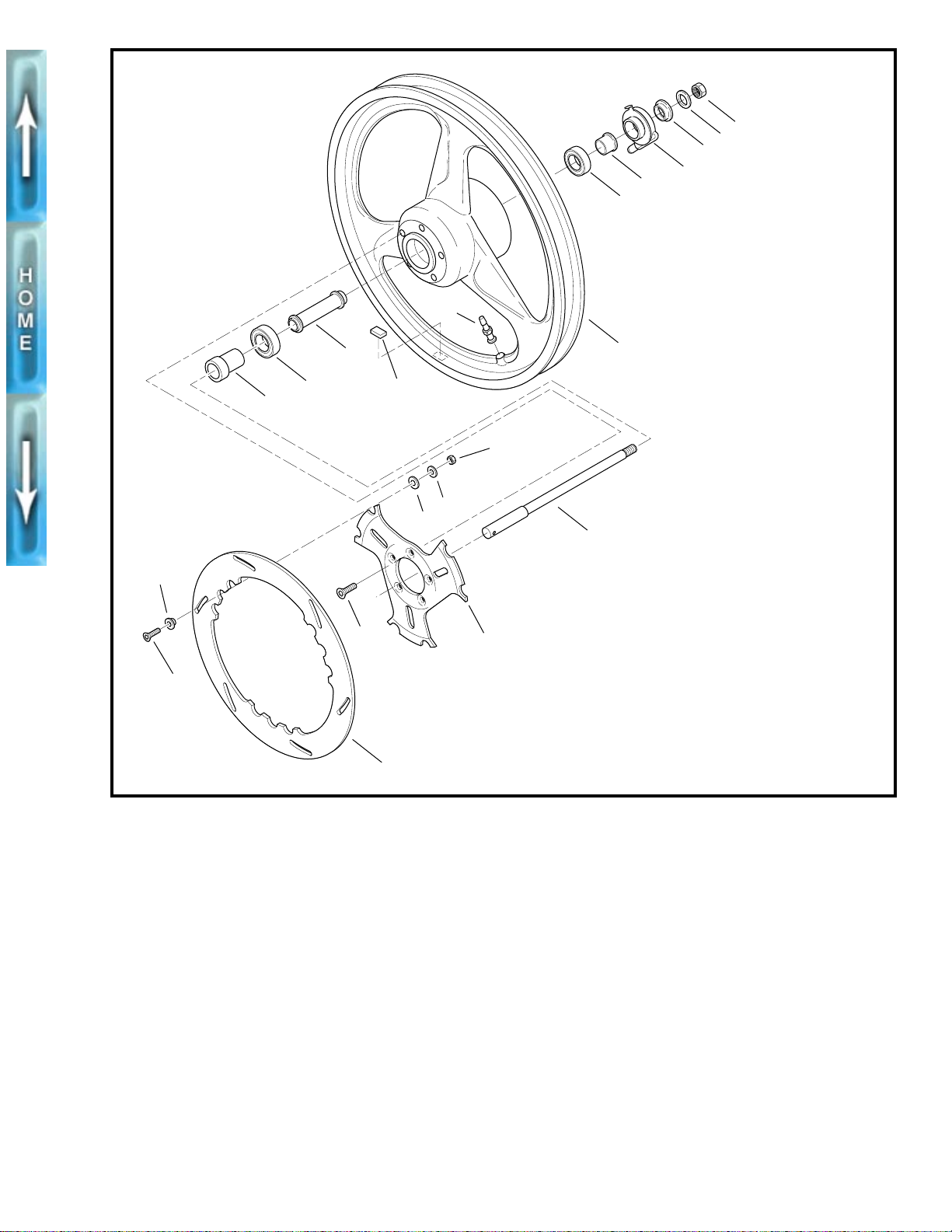
b0196x2x
1
2
3
4
5
6
8
18
19
12
11
10
16
17
7
9
1. Nut (metric)
14
21
20
13
15
2. Washer
3. Speedometer drive
spacer
4. Speedometer drive
5. Left axle spacer
6. Wheel bearing
7. Wheel
8. Valve stem
9. Wheel weight
10. Spacer
11. Wheel bearing
12. Right axle spacer
13. Front axle
14. Locknut (6)
15. Front brake carrier
16. Screw (5)
17. Front brake rotor
18. Brake drive pin (6)
19. Screw (6)
20. Spring washer (6)
21. Washer (6)
Figure 2-6. Front Wheel
ASSEMBLY
1
WARNING
Do not allow brake fluid, bearing grease, lubricants, etc.
to contact brake rotor or reduced braking ability will
occur, possibly resulting in personal injury.
1. See Figure 2-6. Verify that the front brake carrier is thor-
oughly clean. Apply LOCTITE THREADLOCKER 242
(blue) to each screw (16). Install carrier (15) on hub with
five screws. Tighten to 20-22 ft-lbs (27.1-29.8 Nm).
2. Verify that the brake rotor is thoroughly clean. Apply LOC-
TITE THREADLOCKER 242 (blue) to each screw (19).
Install rotor on front brake carrier with six screws, brake
drive pins (18), spring washers (20), washers (21) and
locknuts (14). Tighten to 7.5-8.5 ft-lbs (10.2-11.5 Nm).
3. Install spacer (10).
4. Install
5. On the side of the wheel opposite the brake rotor insert
6. On the right side of the wheel insert right axle spacer
7. Install tire, if removed. See TIRES, INSTALLATION on
8. Verify that wheel and tire are true. See CHECKING
new
wheel bearings (6, 10) into hub using suitable
driver. Press on outer race only.
left axle spacer (5) into hub until it seats in bore. Spacer
sleeve must not be cocked or tilted in bore.
(12) into hub until it seats in bore. Spacer sleeve must
not be cocked or tilted in bore.
page 2-16.
CAST RIM RUNOUT on page 2-14.
2-9
Page 88
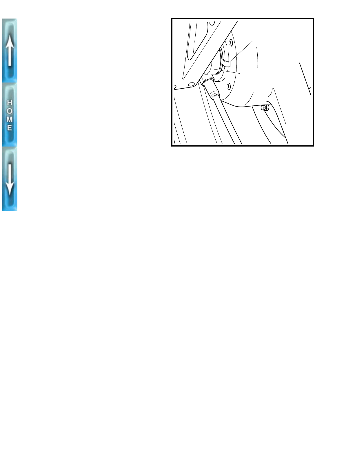
INSTALLATION
1. Apply LOCTITE ANTI-SEIZE LUBRICANT to axle.
2. Position wheel between forks with brake rotor on right
side of vehicle. With pinch screws (metric) loose, insert
threaded end of axle through right side fork. Push axle
through fork and wheel hub until axle begins to emerge
from left side of hub.
CAUTION
1
Speedometer drive tab must be properly inserted or damage to the unit will occur. If drive tab is damaged, it must
be replaced.
3. See Figure 2-7. Align speedometer drive tab and wheel
hub. Push axle through speedometer drive, speedometer
drive spacer and left fork leg.
b0197x2x
Speedometer
drive tab
Speedometer drive
4. Compress the front suspension to make sure it is free
and not binding.
5. See Figure 2-6. Apply LOCTITE THREADLOCKER 242
(blue) to axle nut. Install w asher (2) and axle nut (1) (metric) over threaded end of axle. Insert screwdriver or steel
rod through hole in axle on right side of vehicle. While
holding axle stationary, tighten axle nut to 48-63 ft-lbs
(65.1-71.9 Nm).
6. See Figure 2-5. Tighten the four front axle pinch screws
(2) (metric) to 13-15 ft-lbs (17.6-20.3 Nm).
7. Install front brake caliper. See FRONT BRAKE CALI-
PER, INSTALLATION on page 2-21.
Figure 2-7. Speedometer Drive
2-10
Page 89
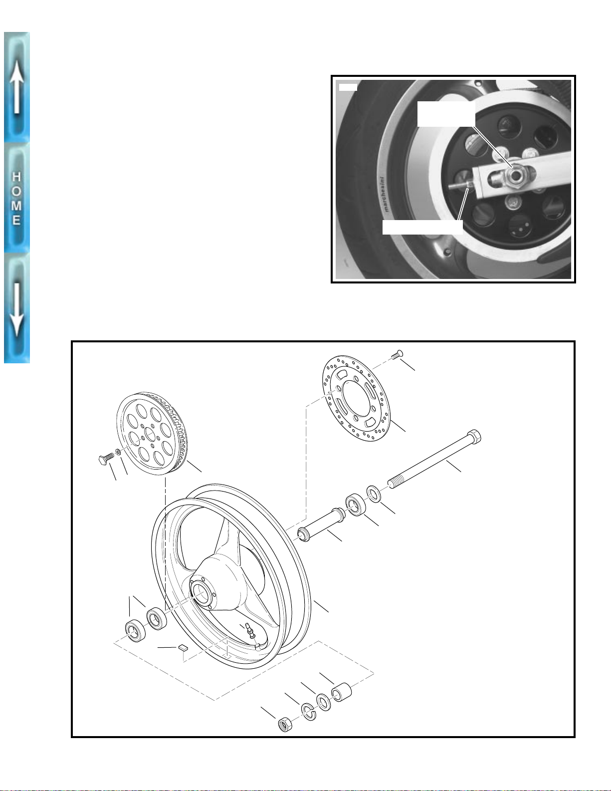
REAR WHEEL
REMO V AL
1. Raise rear wheel off floor using REAR WHEEL SUP-
PORT STAND (Part No. B-41174).
2. Remove rear fender. See FENDERS, REMOVAL/
INSTALLATION on page 2-54.
3. Remove rear brake caliper. See REAR BRAKE CALI-
PER, REMOVAL/DISASSEMBLY on page 2-25.
NOTE
Do not operate rear brake pedal with rear wheel removed or
caliper piston may be forced out. Reseating piston requires
caliper disassembly.
4. See Figure 2-8. Loosen rear axle nut (metric).
5. Loosen rear axle adjuster nuts. Push wheel as far for-
ward as possible.
6. Slip secondary drive belt from bottom of rear wheel
sprocket and remove.
7. See Figure 2-9. Remove rear axle nut (14) (metric), lock-
washer (13), and washer (12). Pull axle (3) and washer
(4) out from left side and remove wheel.
b0013a2x
5574
Rear axle
nut (metric)
Axle adjuster nut
Figure 2-8. Rear Wheel Mounting
17
16
10
1
2
15
3
4
5
6
8
7
9
11
12
13
14
1. Screw (4) (metric)
2. Rear brake rotor
3. Rear axle
4. Washer
5. Wheel bearing
6. Spacer sleeve
7. Wheel
8. Valve stem
9. Wheel weight
10. Bearings (2)
11. Right axle spacer
12. Washer
13. Lockwasher
14. Axle nut (metric)
15. Belt sprocket
16. Washer (5)
17. Bolt (5)
Figure 2-9. Rear Wheel
2-11
Page 90
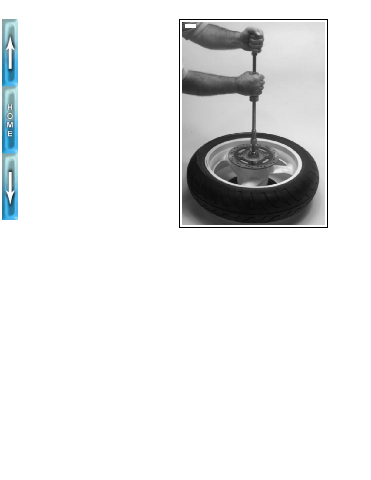
DISASSEMBLY
1. See Figure 2-10. Move wheel to bench area. On the
brake rotor side of the wheel, remove bearing using
BUSHING AND BEARING PULLER (Part No. HD95760-69A) and 1 1/8 in. COLLET (Part No. HD-95769-
69).
2. Remove two bearings from sprocket side of wheel.
3. See Figure 2-9. Remove four screws (1) (metric) to
remove rear brake rotor (2) from hub.
4. Remove five bolts (17) and w ashers (16) on belt sproc ket
(15). Remove belt sprocket from wheel.
CLEANING, INSPECTION AND REPAIR
1. Thoroughly clean all parts in solvent.
1
WARNING
Never use compressed air to “spin-dry” bearings. Very
high bearing speeds can damage unlubricated bearings.
Spinning bearings with compressed air can also cause a
bearing to fly apart, which may result in personal injury.
2. Inspect all parts for damage or excessive wear.
3. Inspect brake rotor. Replace rotor if warped or badly
scored. Measure rotor thickness for excessive wear. Minimum acceptable thickness (0.19 in. (4.8 mm)) is
stamped on side of rotor.
4878
ASSEMBLY
WARNING
1
Do not allow brake fluid, bearing grease, lubricants, etc.
to contact brake rotor or reduced braking ability will
occur, possibly resulting in personal injury.
1. See Figure 2-9. Verify that brake rotor (2) is thoroughly
clean. Apply LOCTITE THREADLOCKER 242 (blue) to
each screw (1) (metric). Fasten rotor to hub with four
screws. Tighten to 35-40 ft-lbs (47.5-54.2 Nm).
NOTE
P/M wheels use a nut (not shown) with each screw (1).
2. Apply two drops of LOCTITE THREADLOCKER 272
(red) to threads of each sprocket bolt (17). Install belt
sprocket (15) using five bolts (17) and washers (16).
Tighten bolts to 55-65 ft-lbs (74.6-88.1 Nm).
Figure 2-10. Removing Wheel Bearing Using Bushing/
Bearing Puller (Part No. HD-95760-69A) and
1 1/8 in. Collet (Part No. HD-95769-69)
3. On the sprocket side of the wheel, insert two bearings
(10) into hub until they contact shoulder for spacer
sleeve. Press bear ings in separately, pressing on outer
race only.
4. Insert spacer sleeve (6) into hub.
5. On the brake rotor side of the wheel, insert bearing (5)
into hub until it contacts end of spacer sleeve. Press on
outer race only.
6. Install tire, if removed. See TIRES, INSTALLATION on
page 2-16.
7. Verify that wheel and tire are true. See CHECKING
CAST RIM RUNOUT on page 2-14.
2-12
Page 91
INSTALLATION
1. Place wheel centrally in the swingarm with the brake
rotor in the caliper. Slide wheel far enough forward to slip
belt over sprocket and then slide wheel back.
2. See Figure 2-9. Apply LOCTITE ANTI-SEIZE LUBRI-
CANT to axle (3).
3. Insert axle (3) through washer (4), left side of swingarm,
rear brake caliper mount, wheel assembly, spacer (11)
and right side of swingarm.
4. Install washer (12), lockwasher (13), and axle nut (14)
(metric) on right side of axle. Do not fully tighten rear axle
nut at this time.
5. Install rear brake caliper. See REAR BRAKE CALIPER,
INSTALLATION on page 2-26.
6. Check for proper belt tension and wheel alignment. See
REAR BELT DEFLECTION in Section 1.
7. Tighten rear axle nut (14) (metric) to 66-73 ft-lbs (89.5-
98.9 Nm).
8. Install rear fender. See FENDERS, REMOVAL/INSTAL-
LATION on page 2-54.
2-13
Page 92
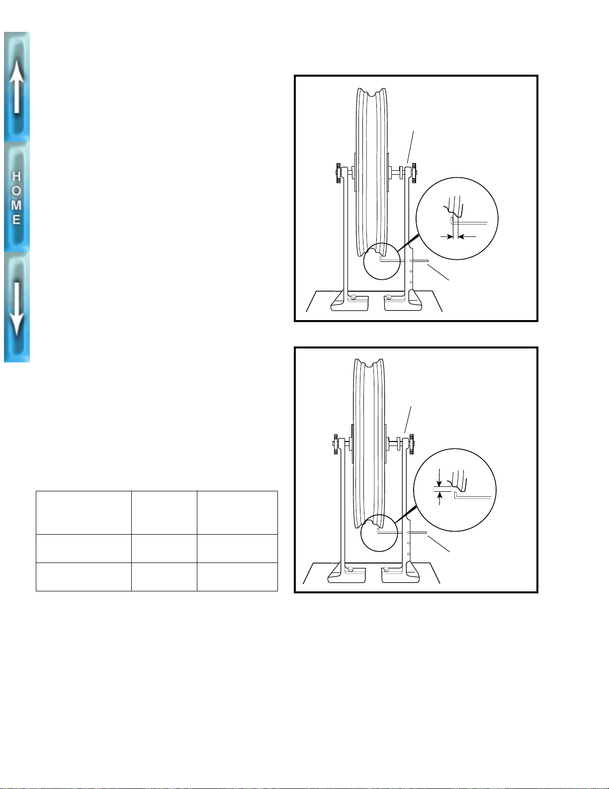
CHECKING CAST RIM RUNOUT
GENERAL
Check wheels for lateral and radial runout before installing a
new
tire.
Rim Lateral Runout
1. See Figure 2-11. Install truing arbor in wheel hub and
place wheel in WHEEL TRUING AND BALANCING
STAND (Part No. HD-99500-80).
2. Tighten arbor nuts so hub will turn on its bearings.
3. Check rim lateral runout by placing a gauge rod or dial
indicator near the rim bead. Replace wheel if lateral
runout exceeds specification shown in Table 2-4.
Rim Radial Runout
1. See Figure 2-12. Install truing arbor in wheel hub and
place wheel in WHEEL TRUING AND BALANCING
STAND (Part No. HD-99500-80).
f1378x2x
Wheel Truing and Balancing
Stand (Part No. HD-99500-80)
Gauge rod
Figure 2-11. Checking Cast Rim Lateral Runout
f1379x2x
2. Tighten arbor nuts so hub will turn on its bearings.
3. Check radial runout as shown. Replace wheel if runout
exceeds specification shown in Table 2-4.
Table 2-4. Wheel Runout
MAXIMUM
WHEEL TYPE
Cast Marchesini 0.040 in.
Aluminum P/M 0.020 in.
LA TERAL
RUNOUT
(1.02 mm)
(0.51 mm)
MAXIMUM
RADIAL
RUNOUT
0.030 in.
(0.76 mm)
0.020 in.
(0.51 mm)
Wheel Truing and Balancing
Stand (Part No. HD-99500-80)
Gauge rod
Figure 2-12. Checking Cast Rim Radial Runout
2-14
Page 93
TIRES
GENERAL
Tires should be inspected for punctures, cuts, breaks and
wear at least weekly.
WARNING
1
Always check both tire sidewalls for arrows indicating
forward rotation. Some tires require different tire rotation
depending on whether tire is used on front or rear wheel.
Installing a tire with the wrong rotation could result in
personal injury.
Some tires have arrows molded into the tire sidewall. These
tires should be mounted on the rim with the arrow pointing in
the direction of forward rotation. The red circle on the sidewall
is a balance mark and should be located next to the valve
stem hole.
REMOVAL
1. Remove wheel from motorcycle. See FRONT WHEEL,
REMOVAL on page 2-8 or REAR WHEEL, REMOVAL
on page 2-11.
2. Deflate tire.
3. See Figure 2-13. Loosen both tire beads from rim flange.
b0198x2x
A bead breaker machine
simplifies tire removal
Figure 2-13. Loosening Beads from Rim Flange
b0199x2x
Pry bead over rim edge and
remove tire from rim
WARNING
1
Do not use excessive force when starting bead over rim.
Excessive force may damage tire or rim and adversely
affect handling resulting in personal injury.
4. If a bead breaker machine is not available, attach RIM
PROTECTORS (Part No. HD-01289) to the rim. Using
tire tools (not sharp instruments), star t upper bead over
edge of rim at valve. Repeat all around rim until first bead
is over rim.
5. See Figure 2-14. Push lower bead into rim well on one
side and insert tire tool underneath bead from opposite
side. Pry bead over rim edge. Remove tire from rim.
6. Remove valve stem if it is damaged or leaks.
7. Mount tire on TIRE SPREADER (Part No. HD-21000) for
inspection and repair procedures.
CLEANING, INSPECTION AND REPAIR
1. Clean inside of tire.
2. If rim is dirty or corroded, clean with a stiff wire brush.
Figure 2-14. Starting Tire Off RIm
b0200x2x
Lubricate rim flange and both
beads before installation
3. Inspect tire for wear and damage. Replace worn tires.
Use TIRE REPAIR KIT (Part No. HD-20000) for tire
repair. Follow the kit manufacturer’s instructions.
Figure 2-15. Starting Bead on Rim
2-15
Page 94
INSTALLATION
WARNING
1
● Only install original equipment (stock) tire valves
and valve caps. A valve or valve and cap combination that is too long may interfere with (strike) adjacent components, damage the valve and cause rapid
tire deflation. Rapid tire deflation could cause loss of
control and personal injury.
● Also, aftermarket valve caps that are heavier than the
stock cap may have c learance at slow speeds; but, at
high speed the valve/cap will be moved outward by
centrifugal force. This outward movement could
cause the valve/cap to strike the adjacent components, damage the valve and cause rapid tire deflation. Rapid tire deflation could cause loss of control
and personal injury.
1. Damaged or leaking valve stems must be replaced.
Place rubber grommet on valve stem with shoulder in
recess of the valve stem head.
2. Install and tighten nut to 42-44 in-lbs (4.7-5.0 Nm).
3. Thoroughly lubricate rim flanges and both beads of tire
with tire lubricant.
4. See Figure 2-15. Starting at the valve stem, start first
bead into the rim well using a bead breaker machine. If
no machine is available, work bead on as far as possible
by hand. Use a tire tool to pry the remaining bead over
rim flange.
5. Start 180° from valve stem hole and place second bead
on rim. Work bead onto rim with tire tools, working
toward valve in both directions.
1WARNING
Do not inflate over 40 psi (2.8 bars) to seat the beads.
Inflating the tire beyond 40 psi (2.8 bars) to seat the
beads can cause the tire rim assembly to burst with f orce
sufficient to cause personal injury. If the beads fail to
seat to 40 psi (2.8 bars), deflate and relubricate the bead
and rim and reinflate to seat the beads, but do not e xceed
40 psi (2.8 bars).
b0087x2x
Tire lateral
runout 0.080 in.
(2.03 mm)
maximum
Gauge
Figure 2-16. Checking Tire Lateral Runout
b0088x2x
Tire radial
runout 0.060
(1.52 mm)
maximum
Gauge
6. Apply air to stem to seat beads on rim. It may be necessary to use a TIRE BEAD EXPANDER (Part No. HD-
28700) on the tire until beads seal on rim.
Checking Tire Lateral Runout
1. See Figure 2-16. Turn wheel on axle and measure
amount of displacement from a fixed point to tire sidewall.
2. Tire tread lateral runout should be no more than 0.080 in.
(2.03 mm). If runout is more than 0.080 in. (2.03 mm),
remove tire from rim.
3. Check rim bead side runout. See CHECKING CAST RIM
RUNOUT on page 2-14. Replace rims not meeting spec-
ifications.
4. Install tire and check again for tire tread lateral runout.
2-16
Figure 2-17. Checking Tire Radial Runout
Checking Tire Radial Runout
1. See Figure 2-17. Tur n wheel on axle and measure tread
radial runout.
2. Tire tread radial runout should not be greater than 0.060
in. (1.52 mm). If runout exceeds specification, remove
tire from rim.
3. Check rim bead runout. See CHECKING CAST RIM
RUNOUT on page 2-14. Replace rims not meeting spec-
ifications.
4. Install tire and check tire tread radial runout again.
Page 95
ADJUSTMENT
Wheel Balancing
Wheel balancing is recommended to improve handling and
reduce vibration, especially at high road speeds.
In most cases, static balancing using WHEEL TRUING AND
BALANCING STAND (Part No. HD-99500-80) will produce
satisfactory results. However, dynamic balancing, utilizing a
wheel spinner, can be used to produce finer tolerances for
best high-speed handling characteristics. Follow the instructions supplied with the balance machine you are using.
WEIGHTS FOR CAST WHEELS
The maximum weight permissible to accomplish balance is
1 oz. (28 g) (total weight applied to the rim). Wheels should
be balanced to within 1/4 oz. (7 g) at 60 MPH (97 KM/H).
These weights are applied to the flat surface of the wheel rim
according to the following procedures.
1. Make sure that area of application is completely clean,
dry, and free of oil and grease.
2. Remove paper backing from weight. For additional adhesive strength, apply three drops of LOCTITE SUPERBONDER 420 to adhesive side of weight. Place weight
on flat surface of wheel rim. Press weight firmly in place
and hold for ten seconds.
Buell specifies WHEEL WEIGHTS (Part No. 43692-94Y)
which have special self-adhesive backings.
3. Allow eight hours for adhesive to cure completely before
using wheel.
2-17
Page 96
BRAKES
GENERAL
The front and rear brakes are fully hydraulic disc brake systems that require little maintenance. The front brake master
cylinder is an integral part of the brake hand lever assembly.
The rear brake master cylinder is located on the right side of
the motorcycle near the brake pedal.
Check the master cylinder reservoirs for proper fluid levels
every 5000 miles (8000 km). See BRAKES in Section 1.
Check brake pads and rotors f or wear every 2500 miles (4000
km). Replace brake pads if friction material is worn to 1/16 in.
(1.6 mm) or less. Replace brake rotors not meeting minimum
rotor thickness. See BRAKES in Section 1.
If determining probable causes of poor brake operation, see
Table 2-5.
Table 2-5. Brake Troubleshooting
CONDITION CHECK FOR REMEDY
1WARNING
● Clean brake system components using denatured
alcohol. Do not use mineral-base cleaning solvents,
such as gasoline or paint thinner. Use of mineralbase solvents causes deterioration of rubber parts
that continues after assembly. This could result in
improper and unsafe brake operation which may
cause personal injury.
● Always test motorcycle brakes at low speed after
servicing or bleeding system. To prevent personal
injury, Buell recommends that all brake repairs be
performed by a Buell dealer or other qualified
mechanic.
● Exercise caution when handling brake fluid. Brake
fluid can cause irritation of eyes and skin and may be
harmful or fatal if swallowed. If swallowed, administer two tablespoons of salt in a glass of warm water
to induce vomiting. Call a doctor immediately. In
case of contact with skin or eyes, flush with plenty of
water. Get medical attention for eyes. KEEP BRAKE
FLUID OUT OF THE REACH OF CHILDREN.
Excessive lever/pedal travel or
spongy feel.
Chattering sound when brake is
applied.
Ineffective brake –
lever/pedal travels to limit.
Ineffective brake –
lever/pedal travel normal.
Brake pads drag on rotor –
will not retract.
Air in system.
Master cylinder low on fluid.
Worn pads.
Loose mounting bolts.
Warped rotor.
Low fluid level.
Piston cup not functioning.
Distorted or glazed rotor.
Distorted, glazed or contaminated
brake pads.
Cup in master cylinder not uncovering
relief port.
Rear brake pedal linkage out of
adjustment.
Bleed brake(s).
Fill master cylinder with approved
brake fluid.
Replace brake pads.
Tighten bolts.
Replace rotor.
Fill master cylinder with approved
brake fluid, and bleed system.
Rebuild cylinder.
Replace rotor.
Replace pads.
Inspect master cylinder.
Adjust linkage.
2-18
Page 97
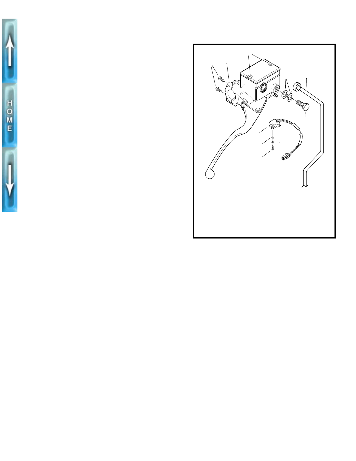
FRONT BRAKE MASTER CYLINDER
REMOVAL
NOTE
The front master cylinder contains no user serviceable parts.
Do not remove the master cylinder unless problems are being
experienced. Replace the entire assembly when necessary.
1. Remove mirror mounting hardware (metric, left hand
threads).
2. Open bleeder nipple cap on front caliper. Install end of a
length of plastic tubing over caliper bleeder valve, while
placing free end in a suitable container. Open bleeder
valve about 1/2-turn. Pump brake hand lever to drain
brake fluid.
3. See Figure 2-18. Remove banjo bolt (6) (metric) and two
gaskets (4) to disconnect brake line from master cylinder.
Discard gaskets.
4. Remove screw (10), lockwasher (9) and washer (8) to
detach brake lamp switch (7).
NOTE
The individual parts of the brake lamp switch are not serviceable. Replace switch upon failure.
5. Remove two screws (1) (metric) and clamp to free master cylinder assembly from handlebar.
INSTALLATION
1. See Figure 2-18. Fasten master cylinder to handlebar by
installing clamp (2) and screws (1) (metric). Tighten
screws to 80-90 in-lbs (9.0-10.2 Nm).
1CAUTION
To avoid leakage, verify that gaskets, banjo bolt, hydraulic brake line and master cylinder bore are completely
clean.
2. Place new gaskets on each side of the hydraulic brake
line. Install banjo bolt through gaskets and brake line fitting into master cylinder. Tighten banjo bolt (6) (metric) to
17-20 ft-lbs (23.0-27.1 Nm).
3. Attach brake lamp switch (7) with screw (10), lockwasher
(9) and washer (8).
4. Remove both master cylinder cover screws (3) and cover.
5. With the master cylinder in a level position, add D.O.T. 5
SILICONE HYDRAULIC BRAKE FLUID. Bring fluid level
to within 1/8 in. (3.2 mm) of molded boss inside front master cylinder reservoir.
b0203a2x
2
1
3
4
5
6
7
8
9
10
1. Clamp screws (2)
(metric)
2. Clamp
3. Master cylinder
cover screws (2)
4. Gaskets (2)
5. Brake line
Figure 2-18. Front Master Cylinder Banjo Bolt
6. Banjo bolt (metric)
7. Front brake lamp
switch
8. Washer
9. Lockwasher
10. Screw
1WARNING
A plugged or covered relief port can cause brake drag or
lockup, which may result in loss of vehicle control and
possible personal injury.
6. Verify proper operation of the master cylinder relief por t.
Actuate the brake lever with the reservoir cover removed.
A slight spurt of fluid will break the surface if all internal
components are working properly.
7. Install master cylinder cover screws (3) and cover.
Tighten cover screws to 9-13 in-lbs (1.0-1.5 Nm).
8. Bleed brake system. See BRAKES in Section 1.
9. Install mirror parallel to handlebars. Mirror mount has
metric, left hand threads.
10. Test brake lamp operation with the brake hand lever
applied and the ignition/headlamp switch turned to IGN.
2-19
Page 98
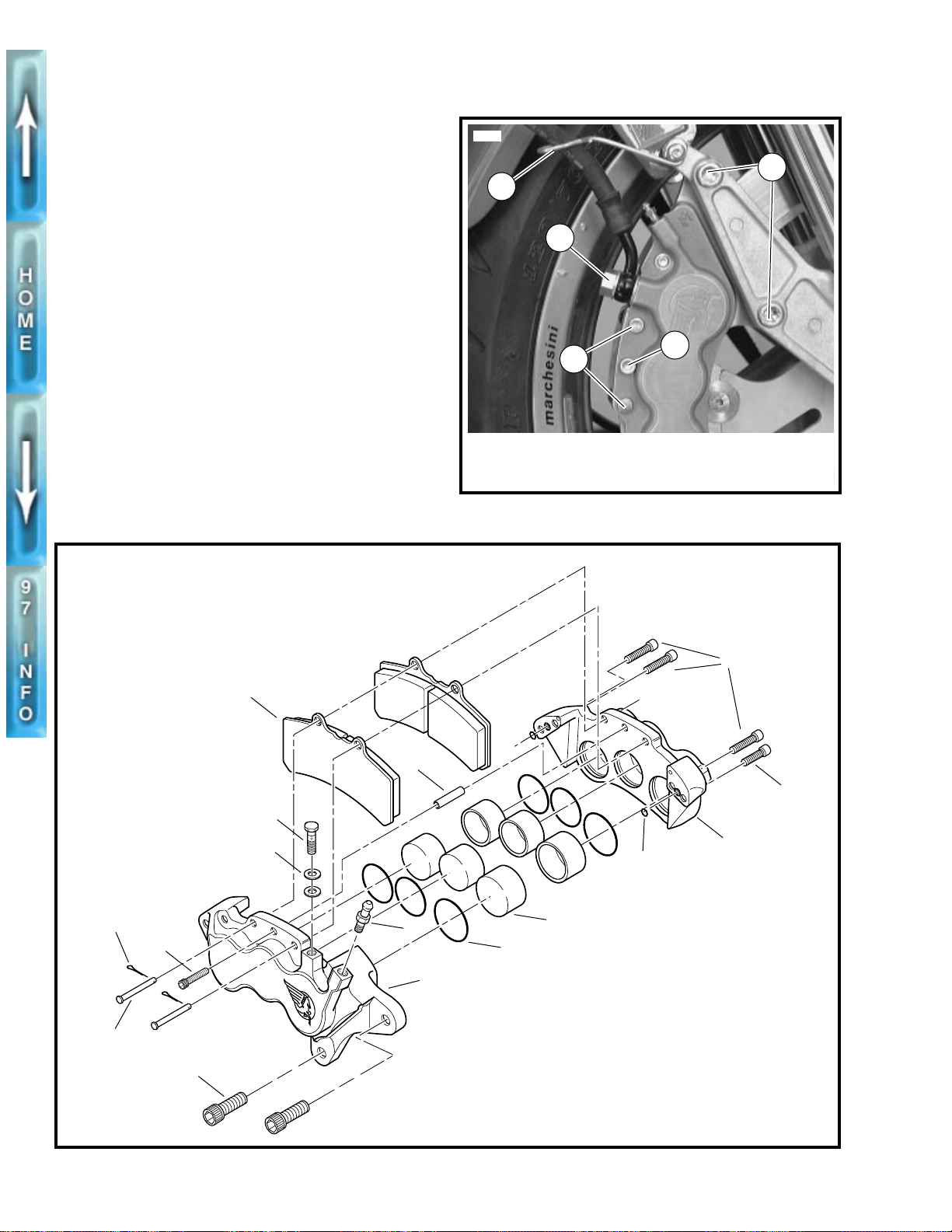
FRONT BRAKE CALIPER
REMOVAL/DISASSEMBLY
NOTE
Step 1 (draining fluid) is not required for caliper removal.
Drain brake fluid only when disassembling caliper.
1. See Figure 2-19. Remove banjo bolt (4) and gaskets to
disconnect brake line from caliper . Drain brake fluid into a
clean, suitable container. Discard gaskets.
2. Remove cotter and support pins (1).
3. Remove center caliper bolt (2) and spacer.
4. Remove brake pads from front brake caliper. Pads must
be removed in order to remove caliper from rotor.
5. Remove both caliper mounting bolts (3).
6. Free caliper from front brake rotor.
7. Move caliper assembly to bench area.
8. See Figure 2-20. Remove screws (13, 14) to separate
caliper halves (7, 12). Remove O-rings (11) and discard.
b0016a2x
5712
5
4
2
1
1. Cotter and
support pins
2. Center caliper bolt
Figure 2-19. Front Brake Caliper Mounts
3. Caliper mounting bolts
4. Banjo bolt
5. Wire guide
Front caliper rebuild kit,
Part No. 44148-94Y
3
14
15
16
13
5
6
12
11
2
8
3
10
9
7
1. Support pins (2)
1
4
2. Cotter pins (2)
3. Center caliper bolt
4. Caliper mounting bolts (2)
5. Banjo bolt
6. Gaskets (2)
7. Right caliper half
8. Bleeder valve
9. O-ring (3 sizes, 2 each)
10. Pistons (3 sizes, 2 each)
11. O-ring (2)
12. Left caliper half
13. Screw
14. Screw (3)
15. Brake pads (2)
16. Spacer
2-20
Figure 2-20. Front Brake Caliper
Page 99
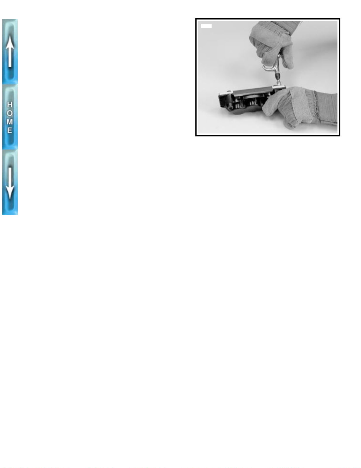
1WARNING
When using air pressure to remove pistons from caliper,
pistons may be ejected with considerable force. Wear
safety glasses, heavy gloves and hold caliper with heavy
towel to prevent personal injury.
1CAUTION
Exercise care to avoid dropping piston on hard surface.
Any damage requires piston replacement.
9. See Figure 2-21. Use BRAKE CALIPER PISTON
REMOVER (Part No. B-42079) to remov e caliper pistons .
10. See Figure 2-20. Pry O-rings (9) out of their respective
grooves on each side of caliper. Discard O-rings.
CLEANING, INSPECTION AND REPAIR
5737
1WARNING
Clean brake system components using denatured alcohol. Do not use mineral-base cleaning solvents, such as
gasoline or paint thinner. Use of mineral-base solvents
causes deterioration of rubber parts that continues after
assembly. This could result in improper and unsafe brake
operation which may cause personal injury.
1. Thoroughly clean brake system components using denatured alcohol. Blow dry using compressed air. Carefully
inspect all components. Replace any parts that appear
damaged or worn. Do not hone caliper piston bore.
2. Inspect brake rotor. Replace if warped or badly scored.
Measure rotor thickness for excessive wear. Replace
rotors less than 0.17 in. (4.3 mm) thick.
1WARNING
Always replace brake pads in complete sets for correct
and safe brake operation. Never replace just one brake
pad. Failure to install brake pads as a set may cause personal injury.
3. Inspect brake pads for damage or wear. Replace both
pads as a set if the friction material of either pad is worn
to 1/16 in. (1.6 mm) or less.
ASSEMBLY
1. See Figure 2-20. Install new O-rings (11) in groove of
each caliper half (7, 12). Install new O-rings (9) in groove
of piston bores.
2. Install pistons (10) in each caliper piston bore.
3. Tighten caliper halves together with four screws (13, 14).
Smallest screw (13) is placed on top next to bleeder
valve (8). Tighten screws to 26-28 ft-lbs (35.2-38.0 Nm).
INSTALLATION
1. Fit caliper on front brake rotor without brake pads.
2. See Figure 2-20. Tighten both caliper mounting bolts (4)
to 30-33 ft-lbs (40.7-44.7 Nm).
3. Insert brake pads (15) from top.
Figure 2-21. Removing Brake Caliper Pistons Using
Brake Caliper Piston Remover (Part No. B-42079)
4. Install center caliper bolt (3) and spacer (16). Tighten
center caliper bolt to 11-13 ft-lbs (14.9-17.6 Nm).
5. Install two support pins (1) and new cotter pins (2).
6. Connect brake line to caliper using new gaskets. Tighten
banjo bolt (5) to 16-20 ft-lbs (21.7-27.1 Nm).
7. With the master cylinder in a level position, v erify that the
brake fluid level is 1/8 in. (3.2 mm) from molded boss
inside reservoir. Add D.O.T. 5 SILICONE HYDRAULIC
BRAKE FLUID if necessary.
1WARNING
A plugged or covered relief port can cause brake drag or
lockup, which may result in loss of vehicle control and
possible personal injury.
8. Verify proper operation of the master cylinder relief por t.
Actuate the brake lever with the reservoir cover removed.
A slight spurt of fluid will break the surface if all internal
components are working properly.
9. Install cover gasket, cover and screws. Tighten screws to
9-13 in-lbs (1.0-1.5 Nm).
10. Depress front brake le ver several times to set brak e pads
to proper operating position within caliper. Bleed brake
system. See BRAKES in Section 1.
11. Test brake lamp operation with the brake hand lever
applied and the ignition/headlamp switch turned to IGN.
NOTE
To allow new brake pads to “wear in” properly with the brake
rotor, av oid making hard stops f or the first 100 miles (160 km).
2-21
Page 100
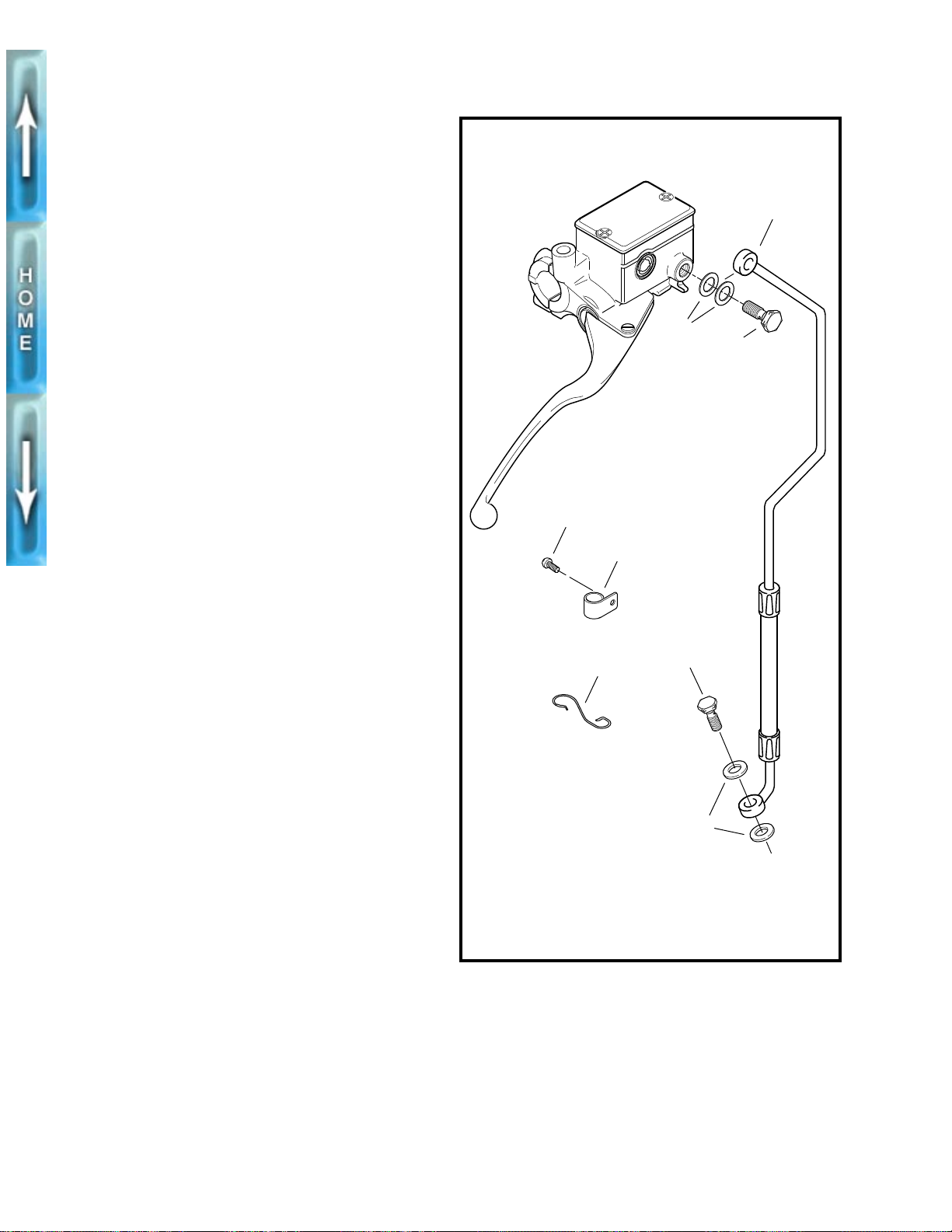
FRONT BRAKE LINE
REMOVAL
1. Open bleeder nipple cap on front brake caliper. Install
end of a length of plastic tubing over caliper bleeder
valve, while placing free end in a suitable container.
Open bleeder valve about 1/2-turn. Pump brake hand
lever to drain brake fluid.
2. See Figure 2-22. Remove screw (4) to detach brake line
clamp (5) from lower triple clamp (right side).
3. Slide brake line out of wire guide (6) on front fender.
4. Remove master cylinder banjo bolt (1) (metric) and two
gaskets (2) to detach brake line from master cylinder
body. Discard gaskets.
5. Remove caliper banjo bolt (7) and two gaskets (8) to
detach brake line from front brake caliper. Discard gaskets.
6. Carefully inspect the brake line for dents, cuts or other
defects. Replace the brake line if any damage is noted.
INSTALLATION
1. See Figure 2-22. Position new master cylinder gaskets
(2) on each side of the banjo fitting. Insert banjo bolt (1)
(metric) through gaskets and banjo fitting. Loosely install
bolt into master cylinder.
2. From the master cylinder, the brake line runs downward
in front of the right handlebar, where it turns inboard at
the upper triple clamp. Loosely install clamp (5), and
screw (4) to attach front brake line to right side of lower
triple clamp.
3. Place brake line inside wire guide (6) on front fender.
4. Position new gaskets (8) on each side of banjo fitting at
free end of brake line. Insert caliper banjo bolt (7)
through gaskets. Loosely install bolt into caliper.
5. Tighten clamp screw (4) on lower triple clamp to 30-35
in-lbs (3.4-4.0 Nm).
6. Tighten master cylinder banjo bolt (1) (metric) to 17-20 ftlbs (23.0-27.1 Nm).
7. Tighten brake caliper banjo bolt (7) to 16-20 ft-lbs (21.7-
27.1 Nm).
8. Install bleeder valve if removed. Refill master cylinder
and bleed brakes. See BRAKES in Section 1.
9. Test operation of brake lever.
10. Tighten front bleeder valve to 4-6 ft-lbs (5.4-8.1 Nm).
Install bleeder cap.
11. Test brake lamp operation with the brake hand lever
applied and ignition/headlamp switch turned to IGN.
b0203x2x
4
Lower right side-
brake caliper
1. Master cylinder
banjo bolt (metric)
2. Master cylinder
gasket (2)
3. Brake line
Figure 2-22. Front Brake Line
Top right side-
master cylinder
3
2
1
5
6
7
8
4. Screw
5. Clamp
6. Wire guide
7. Caliper banjo bolt
8. Caliper gasket (2)
2-22
 Loading...