


 Loading...
2
FRONT FORK
GENERAL
The front fork consists of two telescoping outer tube/inner slider assemblies. Each tube/slider assembly has an internal compression spring which supports the forward weight of the vehicle/rider. The compression spring extends and retracts to cushion the ride over rough or irregular road surfaces. An oilfilled damping mechanism controls the telescoping action of each tube/slider assembly.
See FRONT FORK in Section 1 for fork oil change procedure.
REMOVAL
1.Raise front wheel off floor using FRONT WHEEL SUPPORT STAND (Part No. B-41395) and S1 LIFT ADAPTER (Part No. B-41686).
2.Remove front brake caliper. See FRONT BRAKE CALI- PER, REMOVAL/DISASSEMBLY on page 2-20.
3.Remove front wheel. See FRONT WHEEL, REMOVAL on page 2-8.
4.Remove front fender. See FENDERS, REMOVAL/ INSTALLATION on page 2-54.
5.Loosen left and right headlamp brackets. See HEADLAMP, REMOVAL in Section 7.
6.Loosen all five pinch screws on both the upper and lower triple clamps.
7.Remove front forks.
DISASSEMBLY
1.See Figure 2-30. Clamp the fork vertically in a vise using FRONT FORK HOLDING TOOL (Part No. B-41177).
2.See Figure 2-31. Turn adjuster to full slow position (completely clockwise).
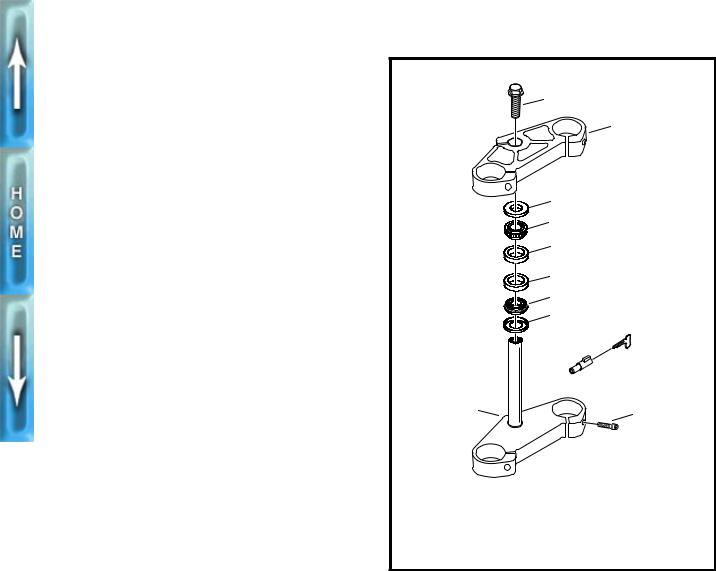
3.See Figure 2-32. Remove fork cap (2) (metric), O-ring (3) and washer (4).
4.Reduce spring pressure and remove both retaining clips (5).
5.Remove preload shim(s) (6) and steel washer (7).
6.Remove fork spring (8).
7.Invert fork and drain fork oil.
8.Clamp fork outer tube (9) horizontally using FRONT FORK HOLDING TOOL (Part No. B-41177). Loosen fork seal retaining ring (14) and spacer ring (13).
9.Using ROBINAIR HEAT GUN (Part No. HD-25070) heat bottom of outer tube. When the tube has sufficiently expanded, drive inner tube (18) from outer tube with a slide hammer action. Inner tube will retain fork oil seal (12) and support ring (11) in place.
10.Spread red retaining cap (15) and remove. Remove upper DU bushing (16) and washer (17).
11.Remove retaining ring (14) and spacer ring (13).
5761
Front Fork Holding Tool,
(Part No. B-41177)
Figure 2-30. Front Fork Holding Tool
b0206x2x
R |
E |
B |
C |
O |
M |
|
|
Left fork leg adjuster- |
Right fork leg adjuster- |
Rebound damping |
Compression damping |
FORK ADJUSTMENTS
Increase rebound/compression (slower):
Turn appropriate adjuster clockwise.
Decrease rebound/compression (faster): Turn appropriate adjuster counterclockwise.
Figure 2-31. Fork Adjusters
12.Remove lower DU bushing (10), support ring (11) and fork oil seal (12). Discard fork oil seal and support ring.
13.Invert fork. Hold damper assembly and remove bolt (20) (metric) and copper washer (19). Discard copper washer.
14.Remove damper assembly (22).
NOTE
The damper assembly (22) contains no user serviceable parts.
2-28

b0033a2x
2
 3 4
3 4 
5
6
7
8
1
NOTE
●Quantities are listed per individual fork leg.
●Left leg controls rebound damping. Right leg controls compression damping.
●Number of preload shims (6) may vary between fork assemblies.
15
16
17
9 |
22 |
18
 10 11
10 11 
|
|
|
12 |
|
19 |
|
|
|
|
|
13 |
|
20 |
21 |
|
|
|
|
|
|
|
|
|
|
|
|
14 |
|
|
|
|
1. |
Front fork assembly |
7. |
Steel washer |
13. |
Spacer ring |
19. |
Copper washer |
2. |
Fork cap |
8. |
Spring |
14. |
Retaining ring |
20. |
Bolt (metric) |
3. |
O-ring |
9. |
Outer tube |
15. |
Retaining cap (red) |
21. |
Bolt (2) (metric) |
4. |
Washer |
10. |
DU bushing (lower) |
16. |
DU bushing (upper) |
22. |
Damper assembly |
5. |
Retaining clip (2) |
11. |
Support ring |
17. |
Washer |
|
|
6. |
Preload shim |
12. |
Fork oil seal |
18. |
Inner tube |
|
|
Figure 2-32. Front Forks
2-29

CLEANING, INSPECTION AND REPAIR
1.Thoroughly clean and inspect all parts. Replace any parts that are bent, broken or damaged.
2.Inspect the O-rings for damage, wear or general deterioration; replace as necessary. Replace all other removed seals.
3.See Figure 2-32. Check inner tube (18). Tube surface should be shiny, smooth and free of scoring or abrasions.
ASSEMBLY
1.Install new fork seal retaining ring (14) and spacer ring (13) on inner tube.
2.See Figure 2-33. Using FRONT FORK BUSHING/SEAL INSTALLER (Part No. B-41176), install new fork oil seal on inner tube. External spring on fork oil seal faces bottom of fork leg.
3.See Figure 2-32. Install new support ring (11).
4.Install upper DU bushing (16) with large end towards the bottom of the fork leg. Install washer (17) and lower DU bushing (10). Install red retaining cap (15).
NOTE
Inspect both DU bushings upon assembly. Bushings are bronze with a Teflon layer. A DU bushing should be replaced when 20-30% of the Teflon layer has been worn through. In this circumstance, a visual inspection will show 20-30% of the bronze base. Also replace bushings if bushing interiors show any small grooves. Such grooves will damage the outside surface of the inner tubes.
5.Clamp outer tube (9) upside down using FRONT FORK HOLDING TOOL (Part No. B-41177).
6.See Figure 2-34. Place inner tube assembly inside outer tube. Using bushing side of FRONT FORK BUSHING/ SEAL INSTALLER (Part No. B-41176), drive in DU bushings until fully seated.
7.Reverse FRONT FORK BUSHING/SEAL INSTALLER. (Part No. B-41176). Seat fork oil seal with seal side of tool. Drop seal retaining ring in place. Fully seat retaining ring.
8.See Figure 2-32. Clamp fork in a horizontal position. Install damper assembly (22) using bolt (20) (metric) and a new copper washer (19). Tighten bolt to 18-23 ft-lbs (24.4-31.2 Nm).
9.Clamp fork upright in the fully compressed stage.
10.Fill fork with oil. See FRONT FORK in Section 1.
11.Install fork spring (8).
12.Pull damper assembly above fork spring. Place steel washer (7) and preload shim(s) (6) on top of spring.
13.Installing the retaining clips (5) requires two people. Have one person compress the spring, steel washer and preload shim(s). At the same time, have the second person install both retaining clips.
14.Install washer (4), new O-ring (3) and fork cap (2) (metric).
5760
Slide fork seal over installer
Figure 2-33. Installing New Fork Seal Using Front Fork Bushing/Seal Installer (Part No. B-41176)
5759
Use tool to fully seat DU bushings
Figure 2-34. Installing Bushings and Seals Using Front Fork Bushing/Seal Installer (Part No. B-41176)
2-30

INSTALLATION
1.Insert fork assembly through front fork triple clamps and headlamp brackets.
NOTE
When installing the front forks, use a screwdriver to pry apart the triple clamps.
2.See Figure 2-35. Position fork tubes so that top of each fork cap fits flush with the top surface of upper triple clamp.
3.Spread LOCTITE ANTI-SEIZE on the last three threads of all five front fork triple clamp pinch screws. Tighten screws to 18-20 ft-lbs (24.4-27.1 Nm).
4.Position headlamp bracket 2.375 in. (60.3 mm) above lower triple clamp. Tighten headlamp bracket screws.
5.Install front fender. See FENDERS, REMOVAL/INSTAL- LATION on page 2-54.
6.Install front wheel. See FRONT WHEEL, INSTALLATION on page 2-10.
7.Install front brake caliper. See FRONT BRAKE CALIPER, INSTALLATION on page 2-21.
8.Set rebound and compression adjusters to the desired settings.
5517
Flush
2.375 in. (60.3 mm)
Figure 2-35. Aligning Front Forks
2-31
FORK STEM AND BRACKET ASSEMBLY
REMOVAL/DISASSEMBLY
1.Remove fork assemblies. See FRONT FORK, REMOVAL on page 2-28.
2.See Figure 2-36. Remove fork stem bolt (1) and upper triple clamp (2).
3.Remove upper dust shield (3) and upper roller bearing (4).
4.Lower the lower triple clamp (6). The lower bearing cone is a press fit on fork stem. Chisel through outer bearing cage to allow rollers to fall free. Apply heat to remove the remaining portion of bearing cone. Continuously move flame around its entire circumference until bearing falls free. Remove lower dust shield (3).
5.If replacement of bearing cups (5) is necessary, drive cups from steering head using STEERING HEAD BEARING RACE REMOVER (Part No. HD-39301A) and UNIVERSAL DRIVER HANDLE (Part No HD-33416).
CLEANING, INSPECTION AND REPAIR
See FRONT FORK in Section 1 for adjustment procedures.
1.See Figure 2-36. Clean the dust shields (3), bearing cups (5), fork stem and lower triple clamp (6) and frame with solvent.
2.Carefully inspect bearing races and assemblies for pitting, scoring, wear and other damage. Replace damaged bearing as a set.
3.Check the fork stem and lower triple clamp (6) for damage. Replace damaged fork stem.
ASSEMBLY/INSTALLATION
b0031a2x
1
2
3
4
5
5
4
3
 9
9
 8
8
6 |
7 |
|
1. |
Fork stem bolt |
6. |
Lower triple clamp |
2. |
Upper triple clamp |
7. |
Screw (5) |
3. |
Dust shield (2) |
8. |
Steering head lock |
4. |
Roller bearing (2) |
9. |
Steering lock key |
5.Bearing cup (2)
Figure 2-36. Bearing Cup Removal
1.See Figure 2-36. If removed, install new bearing cups (5) 5. Install the upper triple clamp (2) and loosely install fork
into frame steering head using STEERING HEAD BEAR- |
stem bolt (11). |
ING RACE INSTALLER (Part No. HD-39302). |
|
2.Liberally coat the bearing cones (4) with grease using WHEEL BEARING PACKER TOOL (Part No. HD-33067). Work the grease into the rollers.
3.Place lower bearing dust shield (3) over fork stem. Find a section of pipe having an inside diameter slightly larger than the outside diameter of the fork stem. Press bearing cone (4) onto fork stem and bracket (1) using the pipe as a press on tool.
4.Insert lower triple clamp (6) through the steering head. Install the upper bracket bearing (4) and dust shield (3) onto fork stem.
6.Install fork assemblies. See FRONT FORK, INSTALLA- TION on page 2-31.
7.Tighten the fork stem bolt (1) until the bearings have no freeplay. Make sure the fork stem turns freely, then tighten the fork stem clamp screw (rearmost pinch screw on upper triple clamp).
8.Check bearing adjustment. See FRONT FORK, ADJUSTMENT in Section 1.
2-32

SWINGARM
REMOVAL
NOTE
Mark all hardware as it is removed so that it may be returned to its original location.
1.Swingarm removal requires motorcycle to be supported in several areas. First, secure front wheel and then raise rear wheel off ground with REAR WHEEL SUPPORT STAND (Part No. B-41174).
1WARNING
To avoid accidental start-up of vehicle and possible personal injury, disconnect the battery cables before proceeding. Always disconnect the negative cable first. If the positive cable should contact ground with the negative cable installed, the resulting sparks may cause a battery explosion producing personal injury.
1CAUTION
Hold battery cable when loosening battery terminal hardware. Failure to hold cable may cause battery damage.
2.Disconnect both battery cables, negative cable first.
3.Remove seat, fuel tank and tail section. See TAIL SEC- TION, REMOVAL on page 2-55.
4.Drain oil tank and remove filter. Detach feed, vent and return hoses from oil tank. See ENGINE LUBRICATION SYSTEM in Section 1.
5.Support motorcycle frame with a floor hoist such as the CENTRAL HYDRAULICS FOLDING CRANE (Model T- 5466).
6.Remove rear fender. See FENDERS, REMOVAL/ INSTALLATION on page 2-54.
7.Remove rear brake caliper assembly from swingarm. See REAR BRAKE CALIPER, REMOVAL/DISASSEM- BLY on page 2-25.
8.Remove rear wheel. See REAR WHEEL, REMOVAL on page 2-11.
9.Remove rear shock. See REAR SHOCK ABSORBER, REMOVAL on page 2-36.
10.Remove rider footrests. See FOOTRESTS, REMOVAL on page 2-52.
11.Remove air cleaner assembly. See AIR CLEANER, REMOVAL in Section 4.
12.Remove carburetor. See CARBURETOR, REMOVAL in Section 4.
13.Remove muffler and exhaust header. See EXHAUST SYSTEM, REMOVAL/DISASSEMBLY on page 2-50.
14.Support engine under crankcase. Avoid pushing tie bar assembly upward.
15.Place a crating strap between the engine cylinders and around the lift. Tighten crating strap until snug.
16.Detach tie bars from frame mounts in the following sequence. Do not remove tie bars from engine.
a.Rear tie bar. Use a swivel socket.
b.Top tie bar.
c.Front tie bar and clutch cable clamp.
17.See Figure 2-37. Remove isolator screws (9) and washers on each side.
18.Slowly raise floor hoist until rubber isolators (10) can be removed. Frame will rise while engine and swingarm remain secured to lift by crating strap.
19.Loosen one pinch screw (8) on the swingarm mount block (7).
20.Remove bearing adjusting bolt (1) on that side with PIVOT SHAFT BEARING ADJUSTER (Part No. B- 41175).
21.Loosen the remaining pinch screw. Extract pivot shaft (5) and second adjuster as an assembly.
22.Remove swingarm.
DISASSEMBLY
1CAUTION
Carefully mark all bearing components as they are removed, so that they may be returned to their original locations. Do not intermix bearing components.
1.See Figure 2-37. Remove and discard swingarm seal (2).
2.Remove roller bearings (3).
NOTE
Remove roller bearing cups (4) only if replacement is required. The complete bearing assembly must be replaced as a unit when replacement is necessary. Do not intermix bearing components.
3.See Figure 2-38. Carefully press roller bearing cups (4) from swingarm using STEERING HEAD BEARING RACE REMOVER (Part No. HD-39301A) and UNIVER- SAL DRIVER HANDLE (Part No. HD-33416).
CLEANING/INSPECTION
1.Clean all components in solvent and blow dry. Carefully inspect all bearing components for wear and/or corrosion. Replace complete bearing assembly if any component is damaged.
2.Check that swingarm is not bent or twisted. Replace if damaged.
ASSEMBLY
1.See Figure 2-39. If necessary, draw new roller bearing cups (4) into swingarm using BEARING INSTALLATION BOLT (Part No. B-35316-5) and STEERING HEAD BEARING RACE INSTALLER (Part No. HD-39302).
2-33
b0210x2x
6
5
2 3 4
1
9 8
7
1.Bearing adjusting bolt (2)
2.Swingarm seal (2)
3.Roller bearing (2)
4.Roller bearing cup (2)
5.Pivot shaft
6.Swingarm
7.Swingarm mount block
8.Pinch screw (2)
9.Isolator screw (2)
10.Rubber isolator (2)
Figure 2-37. Swingarm Assembly and Swingarm Mount Block
NOTE |
INSTALLATION |
Timkin roller bearing assemblies should be replaced as a unit. Do not intermix components. Mark all components so they may be correctly installed.
2.Coat bearing components with WHEEL BEARING GREASE (Part No. HD-99855-89) and assemble.
1CAUTION
Pivot shaft (5) must be installed between inner races (3) or bearing failure can result.
3.Install a new swingarm seal (2) flush to the swingarm.
4.Apply LOCTITE ANTI-SEIZE LUBRICANT to pivot shaft threads.
5.Install one bearing adjustment bolt (1) into pivot shaft (5). Bottom out the adjustment bolt.
6.Slide swingarm assembly into position.
7.Slide pivot shaft assembly through mount block and swingarm. Install the opposing bearing adjustment bolt
(1) using PIVOT SHAFT BEARING ADJUSTER (Part No. B-41175).
8.Tighten one pinch screw (8) into swingarm mount block. Do not tighten the other pinch screw (8) at this time.
1.Adjust swingarm preload. Using a scale as shown in Fig- ure 2-40. Preload should measure 3.5-5.5 lbs (1.6- 2.5 kg).
2.Remove both pinch screws (8). Apply LOCTITE THREADLOCKER 242 (blue) to pinch screw threads.
3.Check that swingarm is centered between mounts. Torque pinch screws (8) to 27-30 ft-lbs (36.6-40.7 Nm).
4.Install rubber isolators and bolts. See SECONDARY DRIVE BELT in Section 6.
5.Attach tie bars to the frame in the following order. Torque to 30-33 ft-lbs (40.7-44.7 Nm)
a.Front tie bar. Clutch cable clamp holds cable on air cleaner side of motor.
b.Top tie bar.
c.Rear tie bar. Tie bar must be horizontal and below frame tab.
6.Install carburetor. See CARBURETOR, INSTALLATION in Section 4.
7.Install muffler and exhaust header. SeeEXHAUST SYS- TEM, ASSEMBLY/INSTALLATION on page 2-50.
8.Install air cleaner. See AIR CLEANER, INSTALLATION in Section 4.
2-34

|
|
|
|
|
|
|
|
5702 |
|
|
|
5701 |
|
|
|
|
|
|
|
|
Figure 2-38. Removing Roller Bearing Cups
9.Install rear shock. See REAR SHOCK ABSORBER, INSTALLATION on page 2-37.
10.Install rear brake caliper assembly. See REAR BRAKE CALIPER, INSTALLATION on page 2-26.
11.Install rear wheel. See REAR WHEEL, INSTALLATION on page 2-13.
12.Install rider footrests. See FOOTRESTS, INSTALLATION on page 2-52.
13.Install rear fender. See FENDERS, REMOVAL/INSTALLATION on page 2-54.
14.Connect and fill lubrication system. SeeENGINE LUBRI- CATION SYSTEM in Section 1.
1WARNING
Always connect positive battery cable first. If the positive cable should contact ground with the negative cable installed, the resulting sparks may cause a battery explosion resulting in personal injury and/or property damage.
1CAUTION
Hold battery cable when tightening battery terminal hardware. Failure to hold cable may cause battery damage.
15. Connect battery cables, positive cable first.
1WARNING
After installing seat, pull upward on front of seat to be sure it is locked in position. If seat is loose, it could shift during vehicle operation and startle the rider, causing loss of control and personal injury.
16.Install tail section, fuel tank and seat. See TAIL SEC- TION, INSTALLATION on page 2-55.
Figure 2-39. Installing Bearings into Swingarm
b0250x2x |
Acceptable preload is |
3.5-5.5 lbs (1.6-2.5 kg) |
Pivot Shaft Bearing |
Adjuster (Part No. B-41175) |
Figure 2-40. Adjusting Swingarm Preload
2-35
REAR SHOCK ABSORBER
GENERAL
See Figure 2-41. The rear suspension features a WP Suspension shock absorber. The shock adjusts for compression and rebound damping as well as spring preload.
The most important rear shock adjustment is the preload setting. Before making any suspension adjustments, set the proper preload. This procedure can be found under SUSPEN- SION ADJUSTMENTSon page 2-39.
NOTE
Rear shock absorber contains no user serviceable parts.
REMOVAL
1.Lift rear wheel off ground using REAR WHEEL SUPPORT STAND (Part No. B-41174).
2.Remove seat, fuel tank and tail section. See TAIL SEC- TION, REMOVAL on page 2-55.
3.Support motorcycle frame with a floor hoist such as the CENTRAL HYDRAULICS FOLDING CRANE.
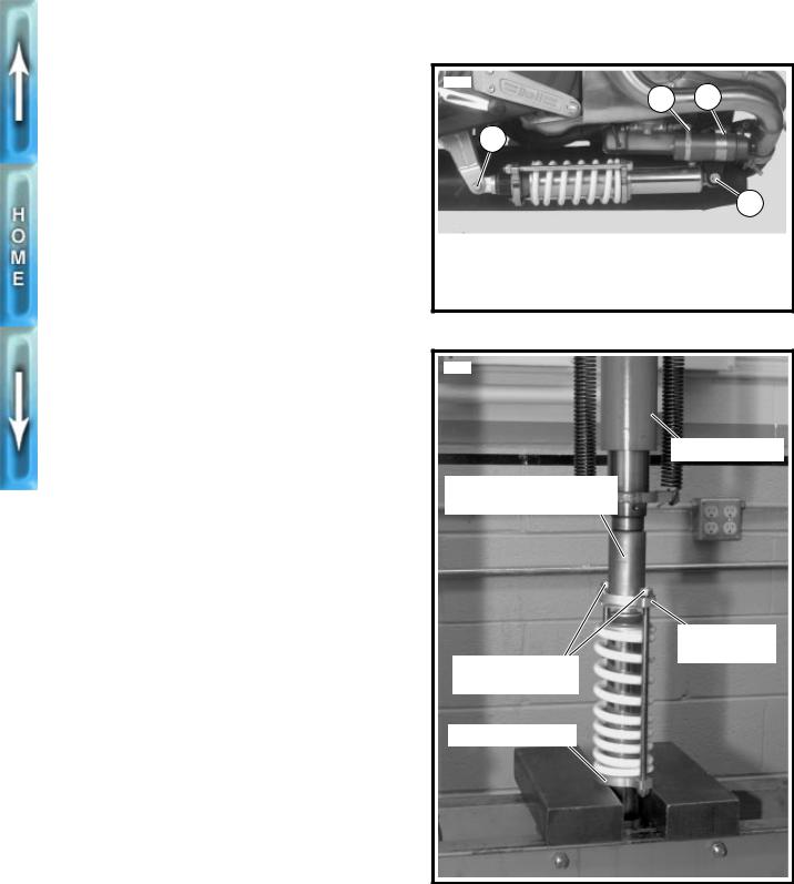
4.See Figure 2-41. Use a flex socket and extension to remove allen screw on front reservoir clamp (3).
5.Remove allen screw and locknut (4) (metric) on front mounting point.
6.Remove allen screw and locknut (1) (metric) on rear mount while supporting shock absorber.
7.Loosen rear reservoir clamp (2).
8.Remove shock absorber assembly.
DISASSEMBLY
1WARNING
The following steps require using a press. Wear eye protection and make certain set-up is stable. The force involved could cause parts to “flyout” at great speeds causing personal injury.
1.See Figure 2-42. Place rear shock absorber in a hydraulic press with REAR SHOCK COMPRESSING TOOL (Part No. B-41178-A) on rear drawing ring.
2.Apply pressure to compress shock spring. Loosen and remove preload adjusting nuts (metric).
3.Release pressure. Remove REAR SHOCK COMPRESSING TOOL (Part No. B-41178-A) and shock from press.
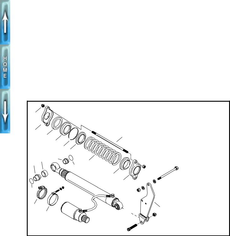
4.See Figure 2-43. Remove rear drawing ring (2).
5.Remove support ring (3) and bump rubber (4).
6.Remove circlip (5) on end of shock cartridge.
7.Remove steel spring retainer (6).
8.Remove spring (7).
5541a
2 3
1
4
1.Rear allen screw and locknut (metric)
2.Rear reservoir clamp
3.Front reservoir clamp
4.Front allen screw and locknut (metric)
Figure 2-41. Rear Shock Mounting Hardware
5129a
Hydraulic press
Rear Shock Compressing
Tool (Part No. B-41178-A)
Rear drawing ring
Preload adjusting nuts (metric)
Front drawing ring
Figure 2-42. Compressing Rear Shock
2-36
ASSEMBLY
1.See Figure 2-43. Install spring (7).
2.Install steel spring retainer (6).
3.Install circlip (5) on end of shock cartridge.
4.Install bump rubber (4) and support ring (3).
1WARNING
The following steps require using a press. Wear eye protection and make certain set-up is stable. The force involved could cause parts to “flyout” at great speeds causing personal injury.
5.See Figure 2-42. Place rear shock absorber in a hydrau- lic press with REAR SHOCK COMPRESSING TOOL (Part No. B-41178-A) on rear drawing ring.
6.Apply pressure to compress shock spring. Install rear preload adjusting nuts (metric).
7.Release pressure. Remove REAR SHOCK COMPRESSING TOOL (Part No. B-41178-A) and shock from press.
INSTALLATION
1.See Figure 2-41. Loosely install reservoir clamps (2, 3).
2.With banjo bolt facing upward, place shock in mounts and loosely install front allen screw and locknut (4) (metric).
3.Loosely install rear allen screw and locknut (1) (metric). Tighten reservoir clamp hardware (2, 3).
4.Tighten front and rear allen screws (1, 4) (metric) to 4045 ft-lbs (54.2-61.0 Nm).
1WARNING
After installing seat, pull upward on front of seat to be sure it is locked in position. If seat is loose, it could shift during vehicle operation and startle the rider, causing loss of control and personal injury.
5.Install tail section, fuel tank and seat. See TAIL SEC- TION, INSTALLATION on page 2-55.
6.Check rear shock preload. See SUSPENSION ADJUST- MENTS on page 2-39.
1 |
|
|
|
|
2 |
8 |
|
|
|
3 |
|
|
||
|
|
|
||
|
4 |
1. |
Preload adjusting nut |
|
|
5 |
|||
|
6 |
|
(2) (metric) |
|
14 |
13 |
2. |
Drawing ring, rear |
|
3. |
Support ring |
|||
15 |
7 |
|||
4. |
Bump rubber |
|||
|
12 |
|||
|
5. |
Circlip |
||
|
3 |
6. |
Spring retainer (steel) |
|
|
9 |
|||
|
7. |
Spring |
||
|
10 |
|||
|
8. |
Rod (2) |
||
12 |
|
9. |
Spring retainer (nylon) |
|
|
10. |
Drawing ring, front |
||
|
|
11. |
Shock mount and |
|
|
|
|
hardware |
|
16 |
11 |
12. |
Seal (4) |
|
13. |
Bushing (2) |
|||
17 |
||||
|
14. |
Heim joint (2) |
||
|
|
15. |
Adaptor bushing (2) |
|
|
|
16. |
Clamp |
|
|
|
17. |
Clamp w/nut and |
|
b0213x2x |
|
|
washer |
|
|
|
|
Figure 2-43. Rear Shock
2-37
Loading...