

Buderus Logamax plus GB142-24, Logamax plus GB142-30, Logamax plus GB142-45, Logamax plus GB142-60 Servicing Instructions
Servicing instructions
WARNING!
Improper installation, adjustment, alteration, service or maintenance can
cause injury, loss of life or property damage. Refer to this manual. For
assistance or additional information consult a qualified installer, service
agency or the gas supplier.
NOTICE!
In the Commonwealth of Massachusetts this boiler must be installed by a
licensed Plumber or Gas Fitter.
Notice:
This manual must be retained for future reference.
– Do not store or use gasoline or other flammable vapors and liquids in
the vicinity of this or any other boiler.
– What to do if you smell gas
• Do not try to light any boiler
• Do not touch any electrical switch; do not use any phone in your
building.
• Immediately call your gas supplier from a neighbor’s phone. Follow
the gas supplier’s instructions.
• If you cannot reach your gas supplier, call the fire department.
–
Installation and service must be performed by a qualified
installer, service agency or the gas supplier.
Warning: If the information in these instructions is
not followed exactly, a fire or explosion may result
causing property damage, personal injury or death.
Condensing gas boiler
Logamax plus
GB142-24/30/45/60
For installers
Please read thoroughly
before servicing
7214 9400 (11/2011) US/CA

Preface
About these instructions
These Servicing Instructions contain important information to
diagnose and resolve issues concerning the GB142 boiler with
capacities 24, 30, 45 and 60 kW.
These Servicing Instructions are intended for specialist installers, who have the necessary training and experience for working
on heating and gas systems.
Subject to technical changes!
Slight changes may be made to the illustrations, process steps
and technical data as a result of our policy of continuous
improvement.
Updating of documentation
Please contact us if you have any suggestions for improvements
or corrections.
Logamax plus GB142-24/30/45/60 - We reserve the right to make any changes due to technical modifications!2

1 Safety and general instructions 4
1.1 Designated use 4
1.2 Hazard definitions 4
1.3 The following instructions must be observed 4
1.4 Observe these instructions for heating
system water 5
1.5 Tools, materials and additional equipment 5
1.6 Inspection 5
1.7 Disposal 5
1.8 Abbreviations 6
2 Regulations and guidelines 7
3 Product description 8
4 Operation 9
4.1 Operating the BC10 basic controller 9
4.1.1 General 9
4.2 Menu structure of the BC10 basic controller 9
4.2.1 "Flue gas test" menu 10
4.2.2 "Service Mode" menu 11
4.2.3 "Manual Operation" menu 12
4.2.4 "Adjustments" menu 12
5Function 14
5.1 General 14
5.2 Structure diagram "Function" 15
Contents
8.1.7 Checking the supply/return/safety/hot-water
temperature sensors 89
8.1.9 Checking the hot-water temperature sensor 91
8.1.10 Checking the supply/return/safety sensors cable 92
8.1.11 Checking the hot surface ignitor; control 92
8.1.12 Checking the hot surface ignitor; resistance 93
8.1.13 Checking the hot surface ignitor; supply cord 93
8.1.15 Testing the ionization current 95
8.1.16 Checking the ionization electrode; cable 95
8.1.17 Checking the ionization electrode;
replace if necessary 96
8.1.18 Checking the gas control valve;
cable connections 98
8.1.20 Checking the gas control valve;
cable connection between gas control valve
and UBA 3 installation base 99
8.1.21 Ohming out the gas control valve 100
8.1.22 Replacing the gas control valve 101
8.1.23 Checking the control unit; connections
to the boiler 104
8.1.24 Bleed the gas supply pipe 106
8.1.25 Measuring the inlet gas pressure
(flow pressure) 107
8.1.26 Measure and adjust the gas/air ratio 108
8.1.27 Measuring the carbon monoxide content (CO) 109
8.1.28 Transformer; replacing 109
8.1.29 Automatic air purging system; replacing 111
8.1.30 Burner; replacing 113
8.1.31 Sight glass; replacing 115
8.1.32 Condensate trap; replacing 116
8.1.33 Pressure sensor; replacing 116
8.1.34 Heat exchanger; replacing 117
8.1.35 UBA 3; replacing 125
6Symptoms 20
6.1.1 General 20
6.1.3 Display codes on the display of the BC10
basic controller 20
6.2 LED on the UBA 3 26
7 Diagnosis 27
7.1 Faults without a fault code 27
7.2 Faults with a fault code 46
8 Actions 84
8.1 Testing, measuring, adjusting and replacing
various components 84
8.1.1 Checking the UBA 3 fuse; replace if necessary 84
8.1.2 External connection board fuse 85
8.1.3 Checking the fan unit; 120 VAC control 86
8.1.4 Checking the fan unit; supply cord (120V AC) 87
8.1.5 Checking the fan unit; tacho cable 88
8.1.6 Replacing the fan unit 88
9 Appendix 126
10 Spare parts 128
Logamax plus GB142-24/30/45/60 - We reserve the right to make any changes due to technical modifications! 3
Safety and general instructions1
1 Safety and general instructions
Please observe these instructions in the interest of your own
safety.
1.1 Designated use
The boiler was designed for heating water for a space heating
system and generating hot water e.g. for domestic purposes.
The boiler is delivered with a BC10 basic controller and the
"Universal Automatic Burner Control Unit 3" (UBA 3) preinstalled.
The boiler can be fitted with a modulating outdoor reset control
AM10 (scope of delivery) and an On/Off thermostat or relay
panel end switch (24 V) (accessories).
1.2 Hazard definitions
The following defined terms are used throughout the documentation to bring attention to the presence of hazards of various risk
levels. Notices give important information concerning the life of
the product.
DANGER:
Indicates the presence of hazards that can
cause severe personal injury, death or substantial property damage.
WARNING:
Indicates the presence of hazards that can
cause severe personal injury, death or substantial property damage.
CAUTION:
Indicates presence of hazards that can cause
minor personal injury or property damage.
CAUTION:
Risk of electric shock.
Indicates presence of hazards due to electric
shock.
NOTICE:
Indicates special instructions on installation,
operation or maintenance that are important but
not related to personal injury or property
damage.
1.3 The following instructions must be
observed
– The boiler must only be used for its designated purpose,
observing the Installation Instructions.
– Only use the boiler in the combinations and with the accesso-
ries and spares listed.
– Other combinations, accessories and consumables must
only be used if they are specifically designed for the intended
application and do not affect the system performance and the
safety requirements.
– Maintenance and repairs must only be carried out by autho-
rized professionals.
– You must report the installation of a condensing gas boiler to
the relevant gas utility company and have it approved.
– You are only allowed to operate the condensing gas boiler
with the combustion air/flue gas system that has been specifically designed and approved for this type of boiler.
– Please note that local permission for the flue system and the
condensate water connection to the public sewer system
may be required.
– You must also observe:
– the local building regulations stipulating the installation rules.
– the local building regulations concerning the air intake and
outlet systems and the chimney connection.
– the regulations for the power supply connection.
– the technical rules laid down by the gas utility company con-
cerning the connection of the gas burner fitting to the local
gas main.
– the instructions and standards concerning the safety equip-
ment for the water/space heating system.
– the Installation Instructions for building heating systems.
– The boiler must be located in an area where leakage of the
tank or connections will not result in damage to the area adja-
cent to the boiler or to lower floors of the structure. When
such locations cannot be avoided, it is recommended that a
suitable drain pan, adequately drained, be installed under the
boiler. The pan must not restrict combustion air flow.
– The boiler must be installed such that the gas ignition system
components are protected from water (dripping, spraying,
rain etc.) during boiler operation and service.
– The boiler must not be installed on carpeting.
– Do not restrict or seal any air intake or outlet openings.
– If you find any defects, you must inform the owner of the sys-
tem of the defect and the associated hazard in writing.
Logamax plus GB142-24/30/45/60 - We reserve the right to make any changes due to technical modifications!4
Safety and general instructions 1
DANGER
if flammable gas explodes.
Beware if you smell gas: there may be an
explosion hazard!
Warning: If the information in these instructions is not followed exactly, a fire or explosion may result causing property damage,
personal injury or death.
Do not store or use gasoline or other flam-
mable vapors and liquids in the vicinity of this
or any other boiler.
What to do if you smell gas
Do not try to light any boiler.
Do not touch any electrical switch; do not use
any phone in your building.
Immediately call your gas supplier from a
neighbor’s phone. Follow the gas supplier’s
instructions.
If you cannot reach your gas supplier, call the
fire department.
Installation and service must be performed by a
qualified installer, service agency or the gas
supplier.
1.4 Observe these instructions for heating
system water
– Thoroughly flush the system prior to filling.
Only use untreated main water to fill and top off the system.
– Do not use salt bedding exchangers to soften the water.
– Do not use inhibitors or other additives!
– No Toxic chemicals such as used for boiler treatment, shall
be introduced into the heating water used for space heating.
– The maximum permissible flow rate of the GB142-24/30 this
is 11 GPM (gal./min.), for the GB142-45 is 15 GPM and for
the GB142-60 is 20 GPM.
– When using oxygen-permeable pipes, e. g. for floor heating
systems, you must separate the system using heat exchang-
ers. Unsuitable heating system water promotes the formation
of sludge and corrosion.
This may damage the heat exchanger or affect its operation.
1.6 Inspection
We advise you to offer your customer an annual inspection and
maintenance contract. If inspection reveals that maintenance
work is necessary you can carry this out as required in the Installation instruction of the boiler.
Installation
CAUTION:
– Check and clean the heating system at least
once a year.
– Carry out a maintenance overhaul if neces-
sary. Immediately repair defects to avoid
damage to the heating system!
– Periodically examine the venting systems and cleaning of the
screens in the vent terminal.
– Also periodically inspect the low water cutoffs, including
flushing of float types.
– And periodically inspect the burner flames (see page 8, fig. 1,
pos. 10).
– Check the neutralization unit if present.
– Check to see if there are no obstructions to the flow combus-
tion and ventilation air.
– For direct vent boilers, proper reassembly and resealing of
the vent-air intake system is required.
Maintenance
– Cleaning the heat exchanger, the burner and the condensate
trap (see installation instructions, Maintenance).
– Checking the ionization signal (par. 8.1.15, page 95)
– Checking and adjusting the gas/air ratio (par. 8.1.26,
page 108).
1.7 Disposal
– Dispose of the boiler packaging in an environmentally sound
manner.
– Dispose of components of the heating system
(e. g. boiler or control device), that must be replaced, by
handing them in to an authorized recycling facility.
– Keep boiler area clear and free from combustible materials,
gasoline and other flammable vapors and liquids.
1.5 Tools, materials and additional equipment
For the installation and maintenance of the boiler you will need
the standard tools for central heating, gas and water fitting.
In addition, a handtruck with a fastening belt is very useful.
Logamax plus GB142-24/30/45/60 - We reserve the right to make any changes due to technical modifications! 5

Safety and general instructions1
1.8 Abbreviations
AM10 = Outdoor reset module
AS = System fault code
AV = Air Vent
BC = Operating code
BC10 = Control panel (on the boiler)
BCT = Boulter Buderus cylinder thermostat
BDV = Boulter Buderus diverter valve
BKS = Blocking boiler fault code
CB = Connection Block
CH = Central Heating
CHF = Central Heating Supply
CHR = Central Heating Return
CM10 = Cascade module
CT = Cylinder Thermostat
CWDO = Condensate water drainage outlet
CM10 = Cascade module
DHW = Domestic Hot Water
DV = Diverter Valve
E=Earth
EM10 = External control module
EMS = Energy management system
FA = Outdoor sensor
HK1 or HK2 = Central Heating line
KIM = Boiler identification module
L = Live Line
LED = Light Emitting Diode
LSV = Lock Shield Valve
MCW = Mains Cold Water
MM10 = Controler for HK2, second Central Heating line module.
N = Neutal
PE = Ground
PL = Permanent hot line
Prog = Programmer
RT or RC = Room Thermostat
SC = Service code
T=Timer
TRV = Thermostatic Radiator Valve
ÜC = Other display codes
UBA 3 = Universal automatic burner control unit 3
VKS = Locking boiler fault code
WC = Wiring Centre
WM10 = Controler for HK1, first Central Heating line
ZV = Two Port Zone Valve
Logamax plus GB142-24/30/45/60 - We reserve the right to make any changes due to technical modifications!6

2 Regulations and guidelines
Regulations and guidelines 2
The installation must conform to the requirements of the authority
having jurisdiction or, in the absence of such requirements, to the
latest edition of the National Fuel Gas Code, ANSI Z223.1. In
Canada, installation must be in accordance with the requirements of CAN/CSA B149.1, Natural Gas and Propane Installation Code.
Where required by the authority having jurisdiction, the installation must conform to the Standard for Controls and Safety
Devices for Automatically Fired Boilers, ANSI/ASME CSD-1.
Install CO detectors per local regulations. The boiler requires
yearly maintenance, see maintenance section see chapter
„8.1.27 Measuring the carbon monoxide content (CO)“ on
page 109.
Operating Limits of the boiler:
Max. boiler temperature: 220 °F (105 °C)
Max. operating pressure: 44 psi (3 bar)
The hot water distribution system must comply with all
applicable codes and regulations. When replacing an existing
boiler, it is important to check the condition of the entire hot water
distribution system to ensure safe operation.
Massachusetts Installations Only:
For direct- vent boilers, mechanical-vent heating boilers or
domestic hot water equipment, where the bottom of the vent
terminal and the intake is installed below four feet above grade
the following requirements must be satisfied:
1) If there is not one already present, a carbon monoxide
detector and alarm shall be placed in a living area outside
the bedrooms. The carbon monoxide detector and alarm
shall comply with NFPA 720 (2005 Edition).
2) A carbon Monoxide detector and alarm shall be located in
the room that houses the boiler or equipment and shall:
a) Be powered by in series on the same electrical circuit as
the boiler or equipment:
b) Have battery back-up power:
c) Meet ANSI/UL 2034 Standards and comply with
NFPA 720 (2005 Edition):
d) Have been approved and listed by a Nationally
Recognized Testing Lab:
3) A product-approved vent terminal must be used, and if
applicable, a Product approved air intake must be used.
Installation shall be in strict compliance with the
manufacturer's instructions. A copy of the installation.
4) A metal or plastic identification plate shall be mounted at the
exterior of the building, four feet directly above the location
of vent terminal. The plate shall be of sufficient size to be
easily read from a distance of eight feet away, and read "Gas
Vent Directly Below".
b) For direct-vent boilers mechanical-vent heating boilers
or domestic hot water equipment where the bottom of
the vent terminal and the intake is installed four feet or
above grade the following requirements must be
satisfied:
1) If there is not one already present, a carbon monoxide
detector and alarm shall be placed in the living area
outside the bedrooms, The carbon monoxide detector
and alarm shall comply with NFPA 720 (2005 Edition).
2) A carbon monoxide detector shall:
a) Be located inn the area where the boiler or
equipment is located:
b) Have battery back-up power:
c) Be a minimum comply with NFPA 720
(2005 Edition).
3) A product-approved vent terminal must be used, and if
applicable, a product-approved air intake must be used.
Installation shall be in strict compliance with the
manufacturer's instructions. A copy of the installation
instructions shall remain with the boiler or equipment at
the completion of the installation.
Logamax plus GB142-24/30/45/60 - We reserve the right to make any changes due to technical modifications! 7
Product description3
1
2
3
6
9
11
13
14
9
16
15
7
5
8
1
4
10
12
13
14
2
3
5
4
6
7
9
11
9
8
10
12
161517
190
170
150
130
90
110
140
130
120
90
100
110
4
7
2
1
5
812
1011
3 6
9
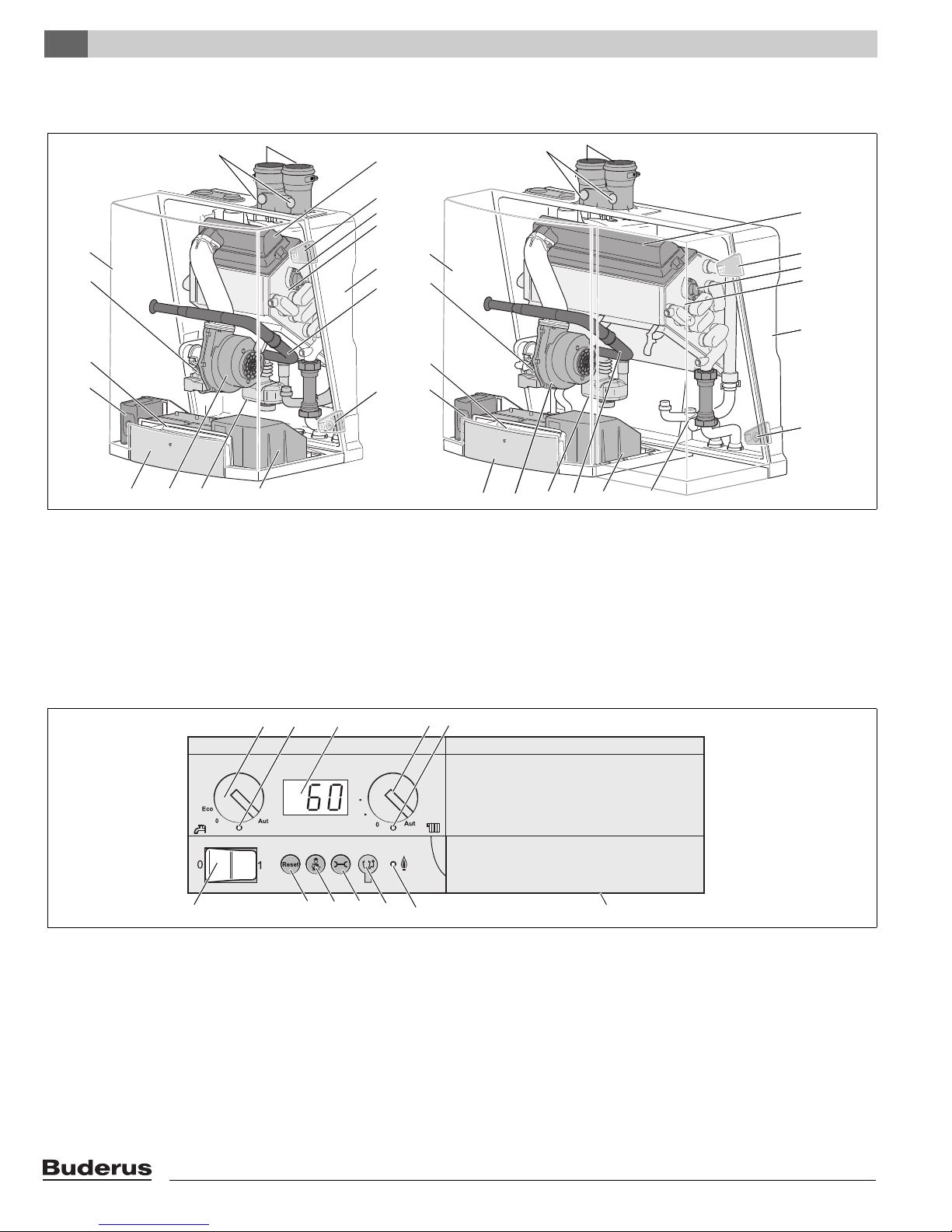
3 Product description
fig. 1 Logamax plus GB142-24/30 (left) and GB142-45/60 (right)
pos. 1: Drawer with control unit
pos. 2: Universal Burner Automat (UBA 3)
pos. 3: Control unit BC10
pos. 4: Gas valve
pos. 5: Cover
pos. 6: Flue measuring points
pos. 7: Parallel flue
pos. 8: Burner
pos. 9: Latches of which two have locks
pos. 10: Sighting glass
pos. 11: Heat exchanger
pos. 12: Back cover
pos. 13: Air intake for the fan
pos. 14: Fan
pos. 15: Condensate trap and internal condensate drain flue
gas pipe
pos. 16: External Connection Board (under the cover)
pos. 17: Pressure sensor
fig. 2 Basic Controller Logamatic BC10
pos. 1: Main switch
pos. 2: DHW temperature knob
pos. 3: LED "DHW status"
pos. 4: Display
pos. 5: Space heating water temperature knob
1)
pos. 6: LED "Heating system status"
1)
ECO mode means that the temperature inside the hot water tank is 140 °F (60 °C), with a hysteresis (ΔT) of 18 °F instead of 9 °F
pos. 7: Under the cover a RC system controller can be installed.
pos. 8: LED "Burner Operation"
pos. 9: Service Tool connector
pos. 10: "Service"
pos. 11: "Chimney sweep"
pos. 12: "Reset"
e button
c button
d button
Logamax plus GB142-24/30/45/60 - We reserve the right to make any changes due to technical modifications!8
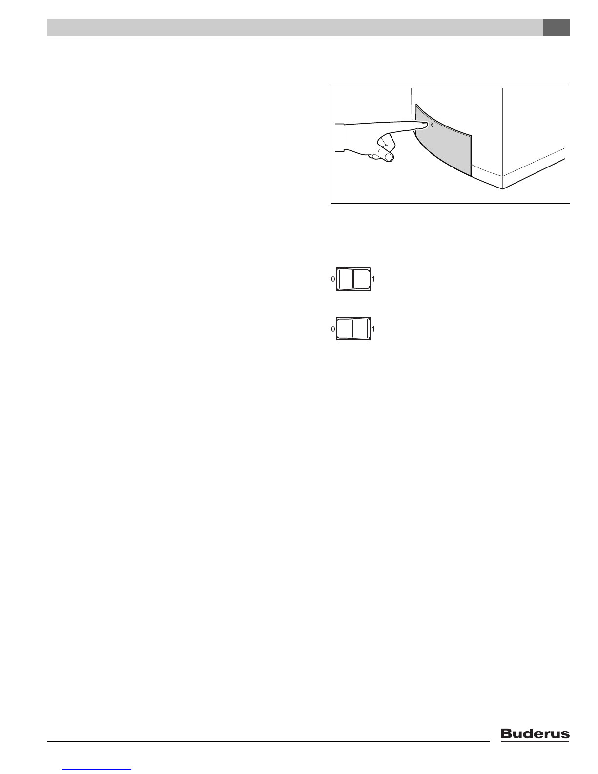
4 Operation
4.1 Operating the BC10 basic controller
4.1.1 General
The boiler is equipped with an control unit, the basic controller
BC10. The BC10 allows you to operate the boiler.
Briefly press on the control panel cover to open it
(see fig. 3).
The basic controller BC10 (see fig. 2) is located on the left side in
the drawer.
On the right side of the drawer there’s space for a RC control unit.
4.1.2 Switching the heating system on and off
Switching on the heating system
Set the main switch on the BC10 basic controller to position "1"
(On).
Switching off the heating system
Operation 4
fig. 3 Opening the control panel
Set the main switch on the BC10 basic controller to position "0"
(Off).
4.2 Menu structure of the BC10 basic controller
The menu structure of the boiler can be viewed on the BC10 using
the "Reset"
fig. 2, pos. 9, 10 and 11) buttons and the display indication (see
fig. 2, pos. 4).
The menu structure consists of 4 menus, schematically
represented on the following pages using structure diagrams:
– "Flue gas test" menu (page 10)
– "Service Mode" menu (page 11)
– "Manual Operation" menu (page 12)
– "Settings" menu (page 12).
c, "Chimney sweep d" and "Service e" (see
Logamax plus GB142-24/30/45/60 - We reserve the right to make any changes due to technical modifications! 9
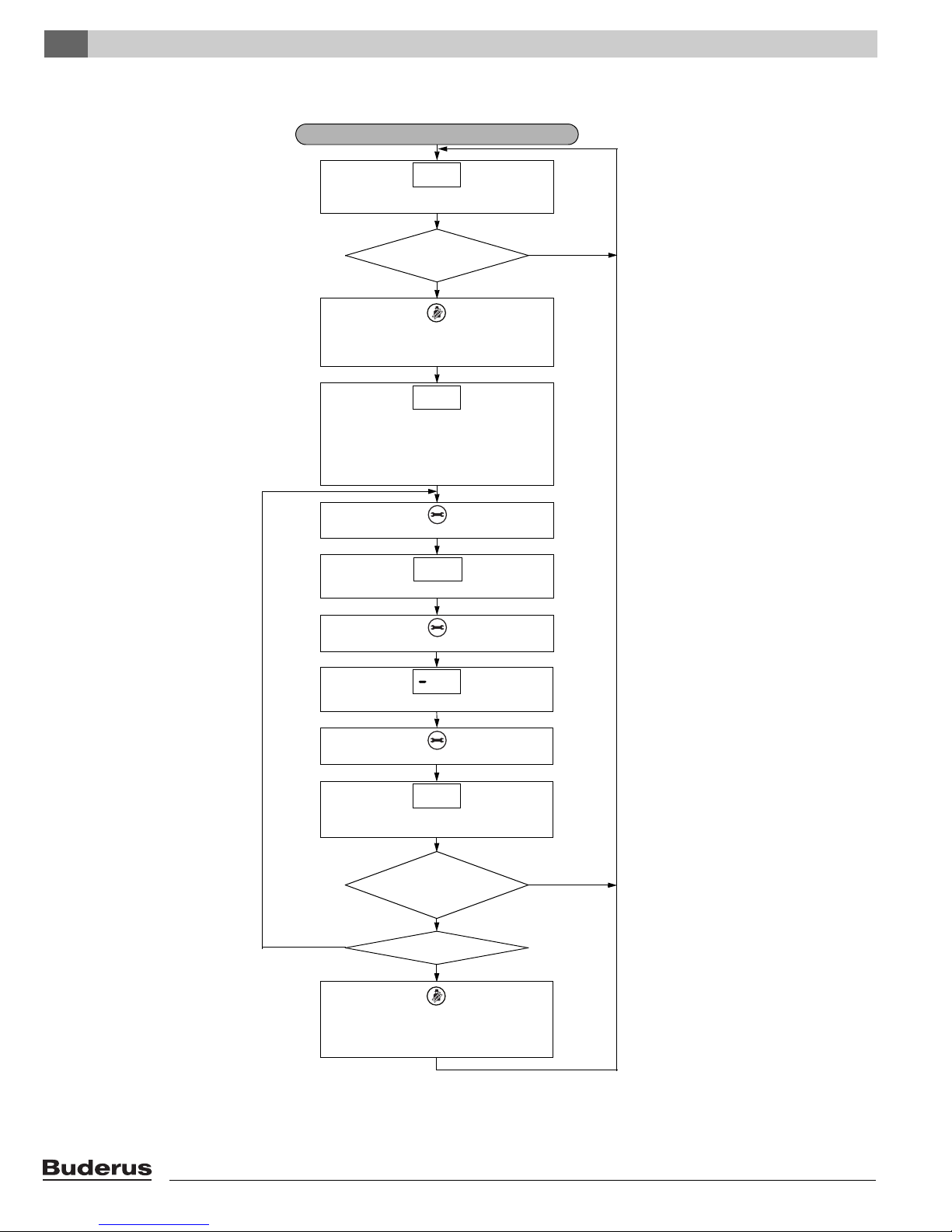
Operation4
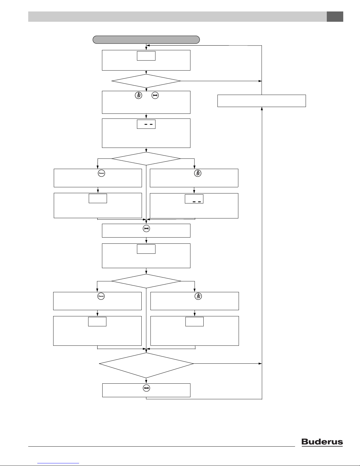
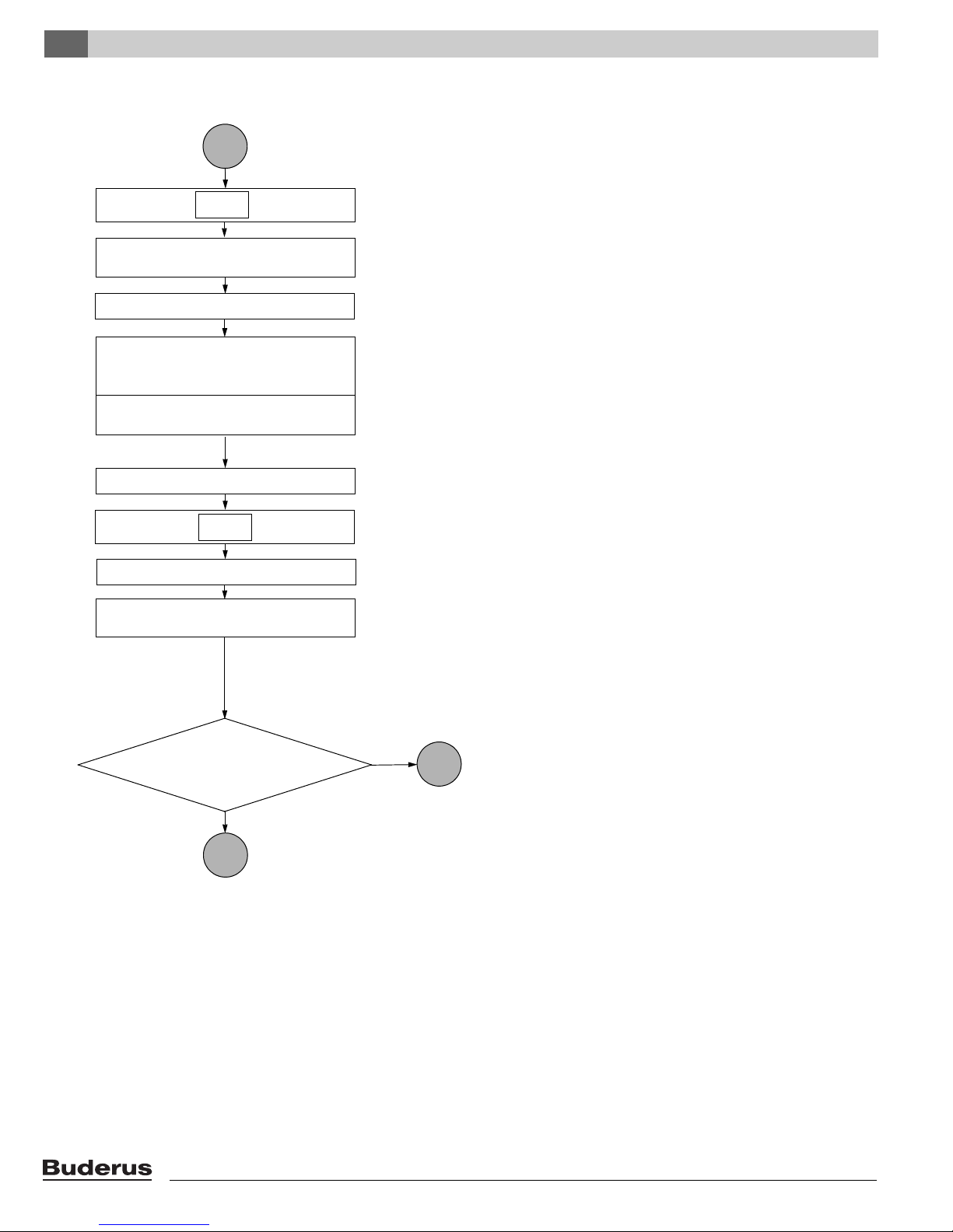
"FLUE GAS TEST" MENU
no
yes
Press the service button.
psi
Current heating system pressure. See page 20.
Operating code. See page 21.
Activate
flue gas test?
Press the service button.
no
Activate flue gas test:
Press and hold the chimney sweep button
2 to 5 seconds.
The flue gas test is activated as soon as a dot is
visible in the lower right hand corner of the
display. This means that the boiler runs in
heating mode at 100 % for 30 minutes. The
maximum boiler water temperature as set on
the BC10 basic controller applies here.
A
.
27
.
Press the service button.
Current supply temperature 0 ... 199 °F
(-18 .. 93 °C). See page 20.
2
7
.
Deactivate
flue gas test?
Deactivate flue gas test:
Press and hold the chimney sweep button for
more than 2 seconds, until the decimal point
has disappeared.
yes
no
Current supply temperature 0 ... 199 °F
(-18 ... 93 °C). See page 20.
27
yes
Have
30 min. passed or
was the power
interrupted?
9P
2
.
4.2.1 "Flue gas test" menu
Logamax plus GB142-24/30/45/60 - We reserve the right to make any changes due to technical modifications!10
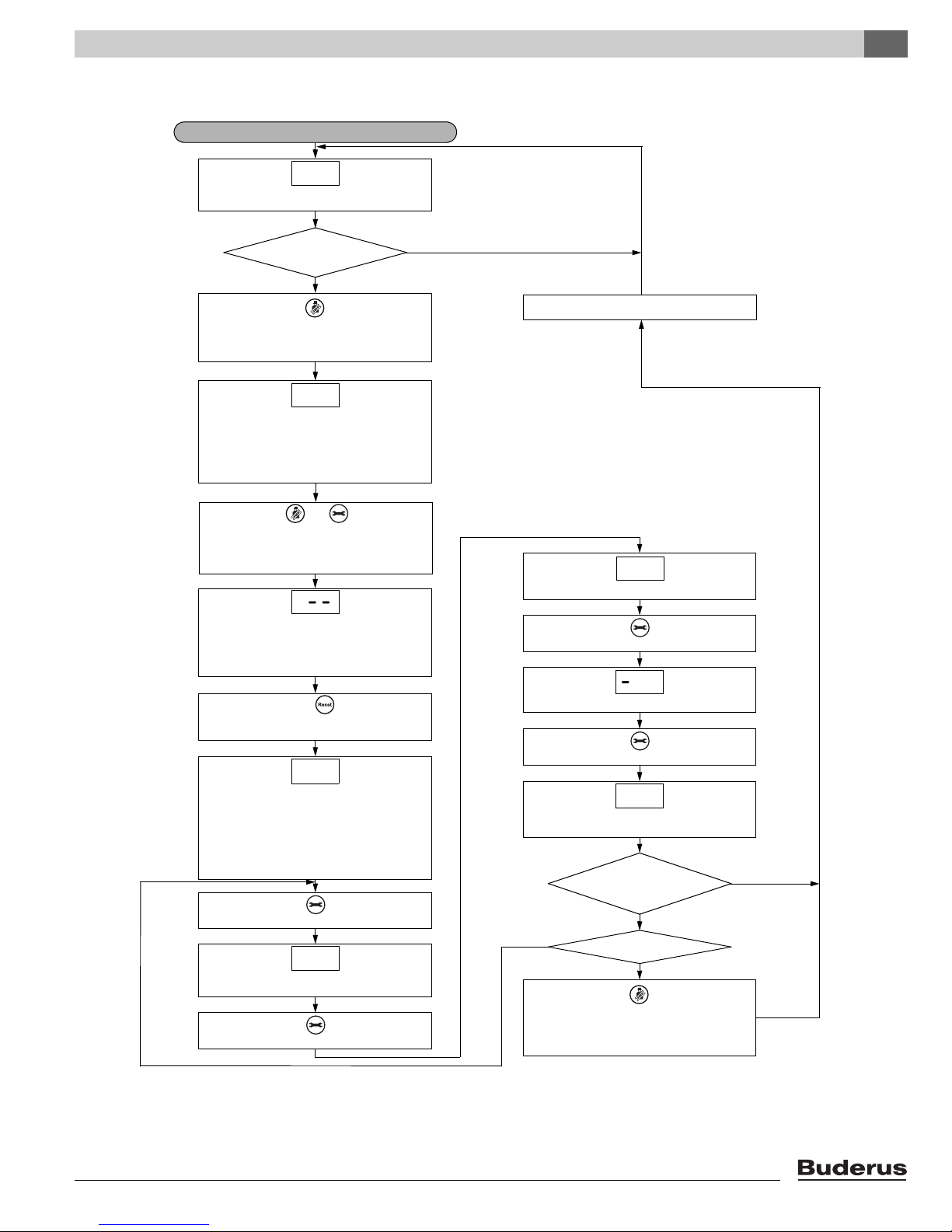
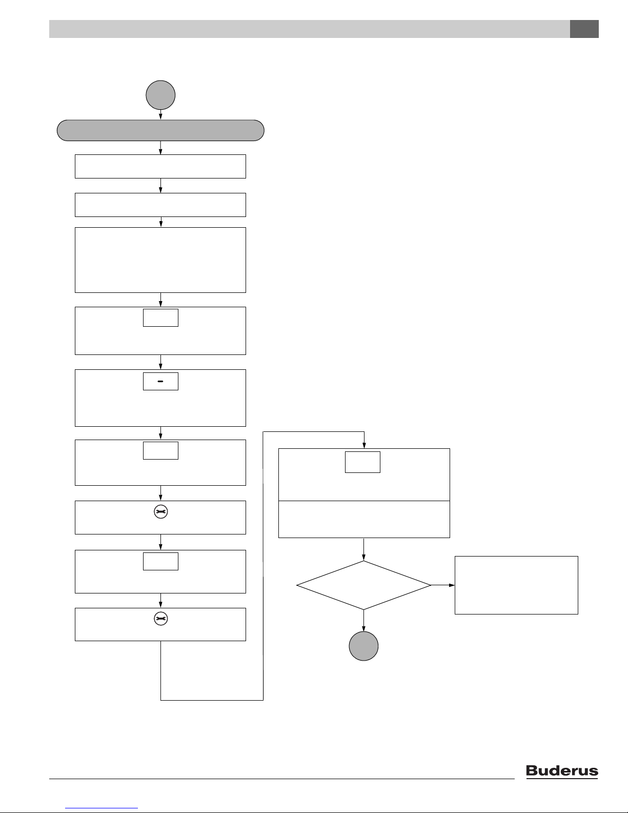
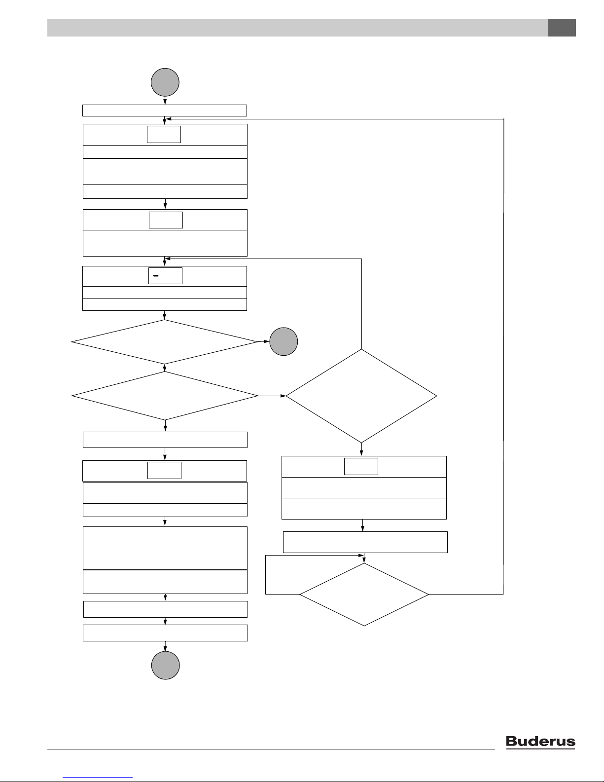
4.2.2 "Service Mode" menu
psi
Current heating system pressure. See page 20.
"SERVICE MODE" MENU
Activate service mode 2nd step:
Simultaneously press and hold the "Chimney
sweep" and "Service" buttons for more than
2 seconds.
Activate
service mode?
no
Activate service mode 1st step:
Press and hold the "Chimney sweep" button
for 2 to 5 seconds.
As soon as a non-flashing dot is shown in the
right-hand bottom corner of the display, the
boiler will run in heating mode at 100 % load for
30 minutes. The maximum boiler water
temperature set on the BC10 basic controller
applies.
27
.
Boiler load in line with "Settings" menu.
+
Current boiler load. See page 20.
Service mode activated.
You can now temporarily lower the boiler load
to partial load to check, and if relevant set the
gas/air ratio or the ionization current.
L
.
Press and hold the "Reset" button until the
display shows "L30."
-
Press the "Service" button.
Press the "Service" button.
Current boiler load. See page 20.
The boiler will reduce its load to 30 % within a
couple of seconds. The maximum boiler water
temperature as set on the BC10 basic controller
applies. Check the gas/air ratio (see page 108)
or the ionization current (see page 95) and
adjust the gas/air ratio if necessary.
03L .
Have 30 min.
passed or was the
power interrupted?
Operating code. See page 46.
Press the "Service" button.
.
Press the "Service" button.
Current supply temperature 0 ... 199 °F
(-18 ... 93 °C). See page 20.
27
.
Deactivate
service mode?
Deactivate service mode:
Press and hold the "Chimney sweep" button for
more than 2 seconds until the decimal point
has disappeared.
no
yes
yes
Current supply temperature 0 ... 199 °F
(-18 ... 93 °C). See page 20.
27
Current supply temperature 0 ... 199 °F
(-18 ... 93 °C). See page 20.
no
27
.
yes
9P
2
.
A
Operation 4
Logamax plus GB142-24/30/45/60 - We reserve the right to make any changes due to technical modifications! 11
Operation4
"MANUAL OPERATION" MENU
yes
Power
interrupted?
Press the "Service" button.
psi
Current heating system pressure. See page 20.
Operating code. See page 20.
During manual operation the "Adjustments"
menu on page 12 can be used to temporarily
change the required boiler load in case of an
emergency.
Activate manual
operation?
Press the "Service" button.
no
To activate manual operation:
Press and hold the "Chimney sweep" button for
more than 5 seconds.
As soon as a flashing dot is shown in the right-
hand bottom corner of the display, manual
operation is active. The means that the boiler is
permanently in heating mode. The maximum
boiler water temperature as set on the BC10
basic controller now applies. The "Heat
request" LED is lit.
Press the "Service" button.
Current supply temperature 0 ... 199 °F
(-18 ... 93 °C). See page 20.
Deactivate manual
operation?
no
2
7
.
9P
2
.
27
.
Deactivate manual operation:
Press and hold the "Chimney sweep" button for
more than 2 seconds until the flashing decimal
point has disappeared.
Current supply temperature 0 ... 199 °F
(-18 ... 93 °C). See page 20.
27
H
.
no
yes
yes
4.2.3 "Manual Operation" menu
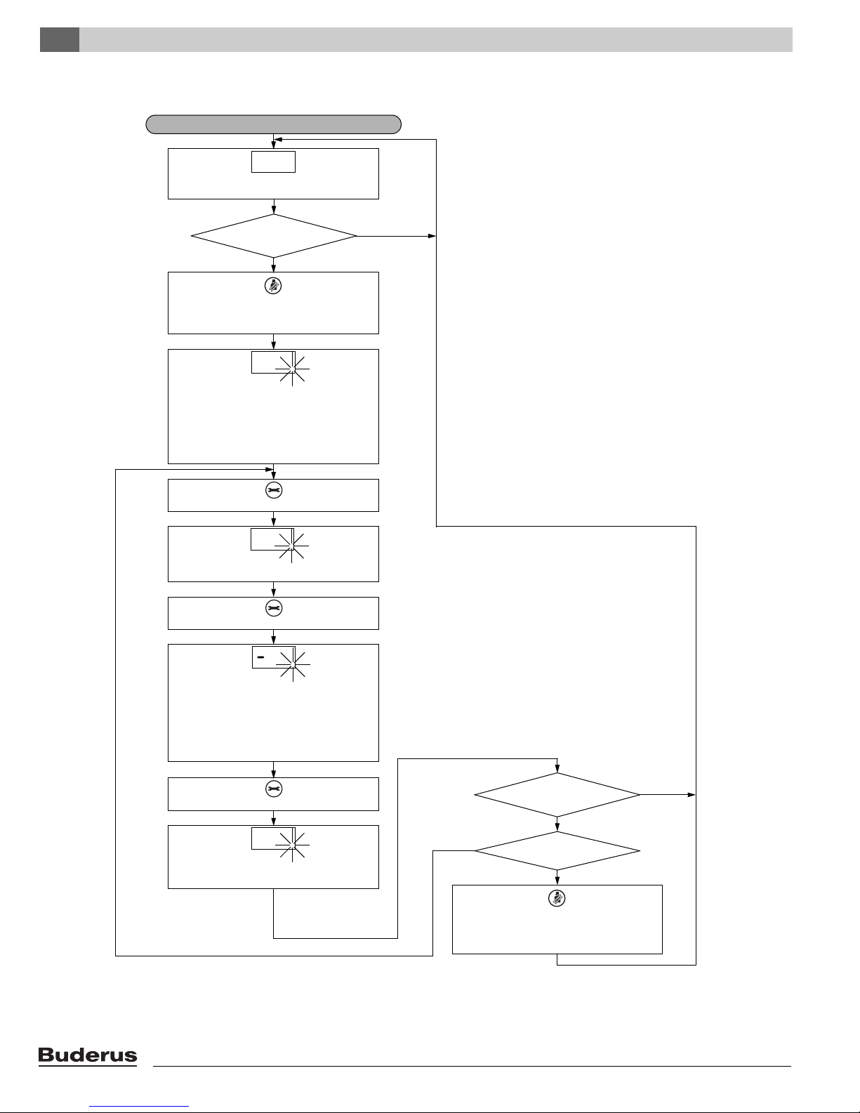
4.2.4 "Adjustments" menu
Logamax plus GB142-24/30/45/60 - We reserve the right to make any changes due to technical modifications!12
"ADJUSTMENTS" MENU
Open programming mode: Simultaneously
press and hold the "Chimney sweep" and
"Service" buttons for more than 2 seconds.
Open the
“Adjustments” menu?
no
Boiler load and pump post purge
time settings confirmed.
+
As soon as the display shows "L--", the
programming mode is open. The first
parameter shown on the display is used to set
the boiler load for heating operation.
Adjust the boiler load with
the "Reset" button.
-
Press the "Service" button.
Have at least
5 min. passed without a button being
pressed or was the power supply
interrupted ?
As soon as the display shows "F ", the second
parameter can be set. This parameter
indicates the pump post purge time.
no
L
Adjust boiler load?
Adjust the boiler load with
the "Chimney sweep" button.
+
The setting "L30" means that the
heating load is lowered to 30 %.
„L__“ is the maximum
heating load setting of 100 %.
Factory default setting: "L " = 100 %.
03L
L
yes, higher
yes, lower
5F
Adjust pump post
purge time?
"F00" is the minimum pump post purge time
setting in minutes. "F60" is the maximum
pump post purge time setting in minutes.
"F1d" is the maximum
pump post purge time setting for one day.
Factory default setting "F 5" = 5 minutes.
no
yes, higher
yes, lower
Adjust the pump post purge time with
the "Reset" button.
-
Adjust the pump post purge time with the
"Chimney sweep" button.
+
00F 1dF
Press the "Service" button.
yes
no
yes
Current supply temperature 0 ... 199 °F
(-18 ... 93 °C). See page 20.
27
Operation 4
Logamax plus GB142-24/30/45/60 - We reserve the right to make any changes due to technical modifications! 13

Function5
5Function
5.1 General
To clarify the operation of the Logamax plus GB142-24/30/45/60
thermal power gas boilers under normal operating conditions, the
work steps are schematically represented in the structure diagrams
on the following pages of this chapter.
Logamax plus GB142-24/30/45/60 - We reserve the right to make any changes due to technical modifications!14
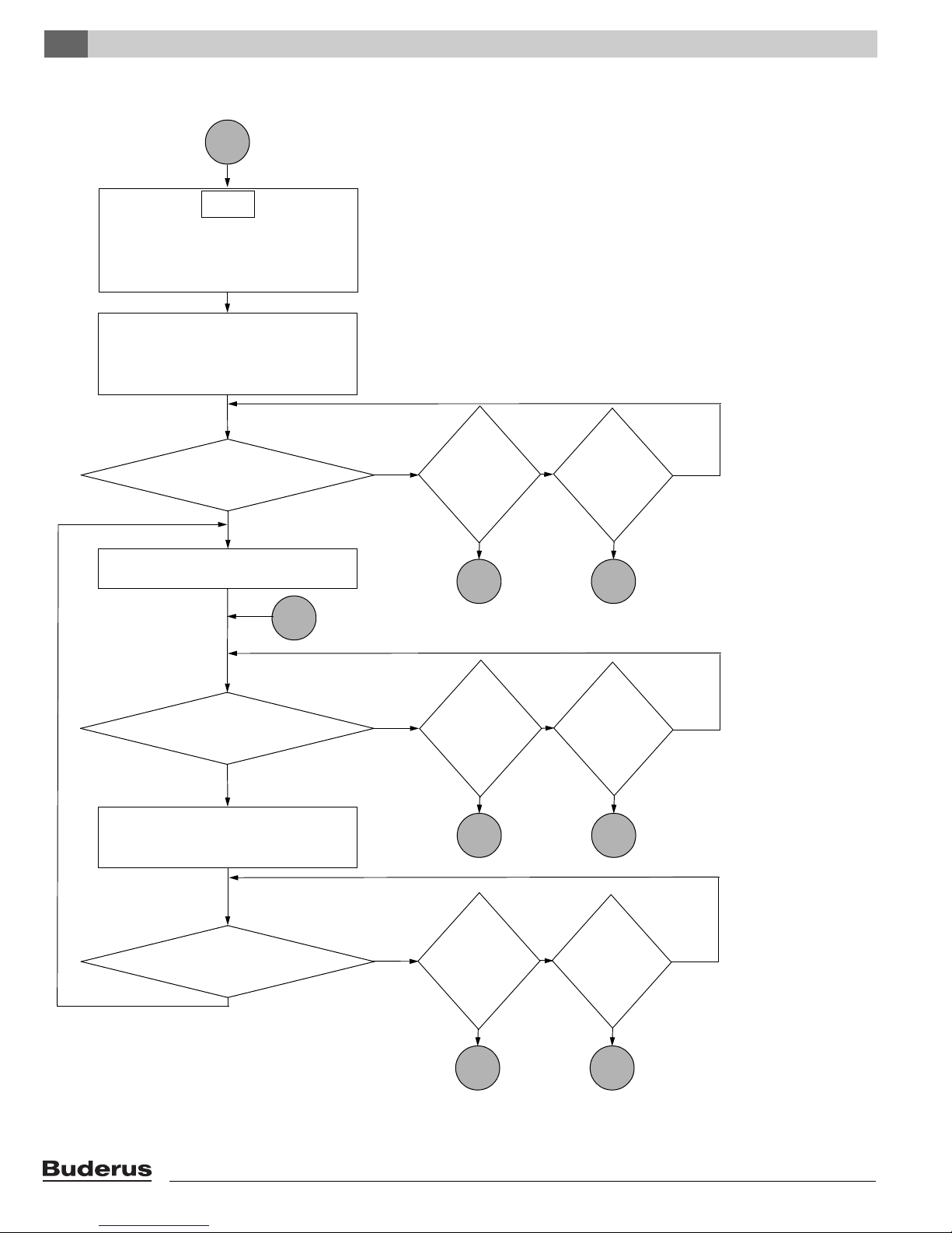
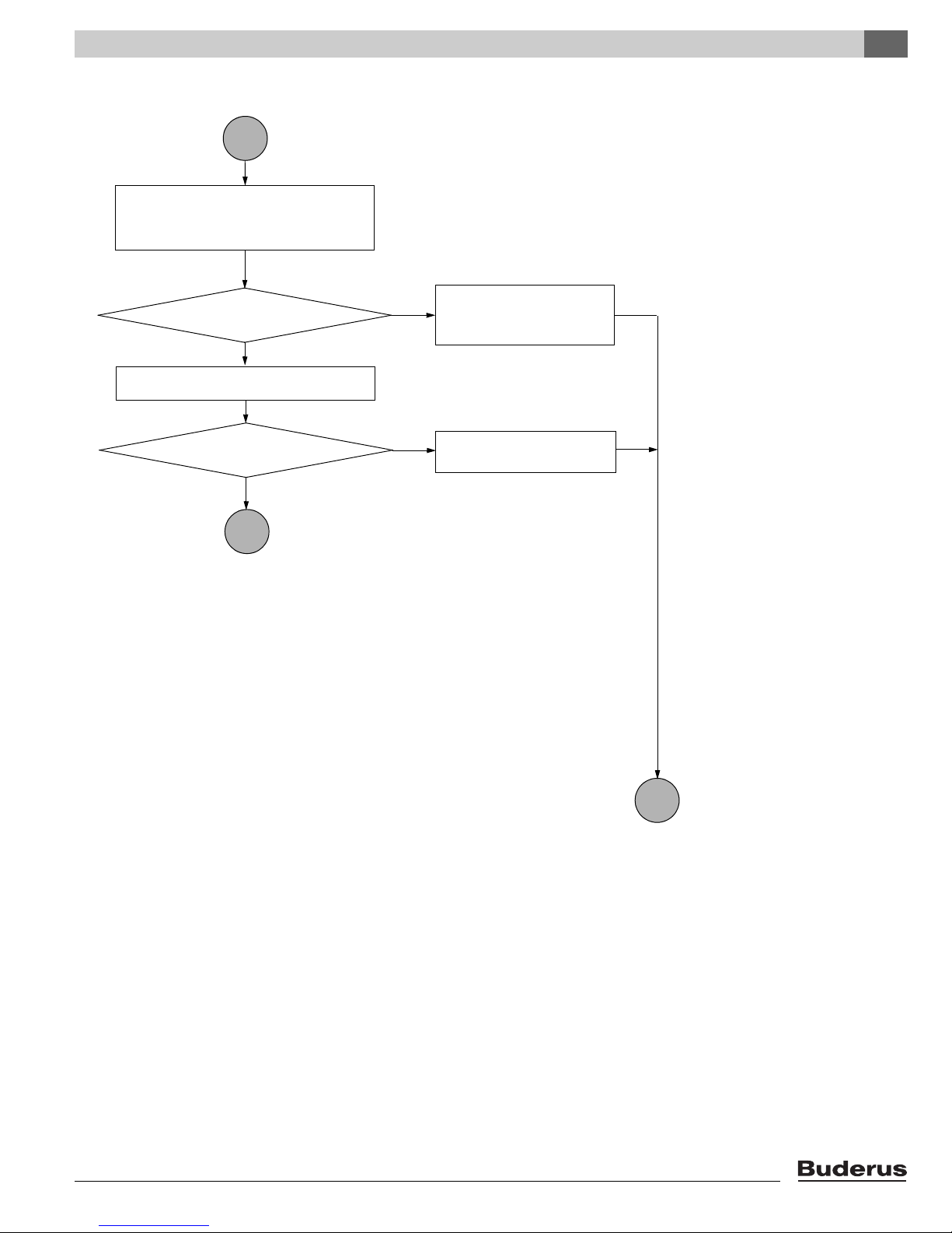
5.2 Structure diagram "Function"
1
Start up
Connect the heating system to the power grid
by turning the circuit breaker ON.
Turn the main switch on the BC10 to
position “1” (ON), see page 8, fig. 2.
A display check is carried out
(for max. 1 second).
888 ...
Flashes twice for 2 seconds until
communication between the UBA 3 and the
BC10 has been established.
Press the "Service" button.
Current heating system pressure.
See page 20.
Press the "Service" button.
Operating code.
The heating boiler is started.
U0
Is the
air purging phase
okay?
Unit will show an error code.
Fault must be fixed before
proceeding.
See chapter 6, 7 and 7.2.
no
2
yes
Current supply temperature 0 ... 199 °F
(-18 ... 93 °C). See page 20.
27
page 16
Start of air-side pre-flushing phase.
The blower runs for < 20 seconds at
approx. 60 % of the maximum speed.
The LED of the UBA 3 lights for 1 second.
This means that the UBA 3 is reading the
KIM. If a new KIM or UBA 3 has been
installed, the LED will flash at a high
frequency for max. 10 sec. while data is being
exchanged.
9P
2
psi
Function 5
Logamax plus GB142-24/30/45/60 - We reserve the right to make any changes due to technical modifications! 15
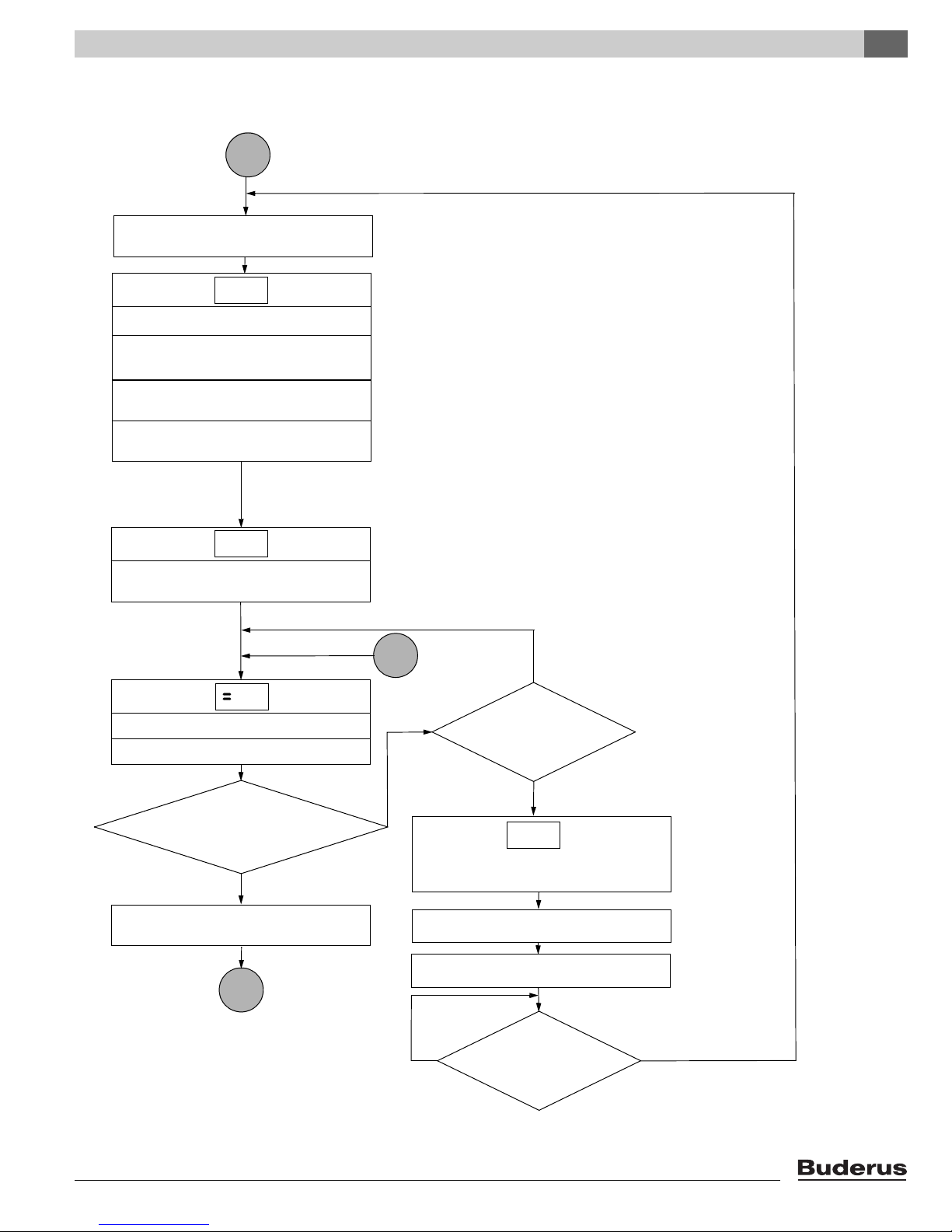
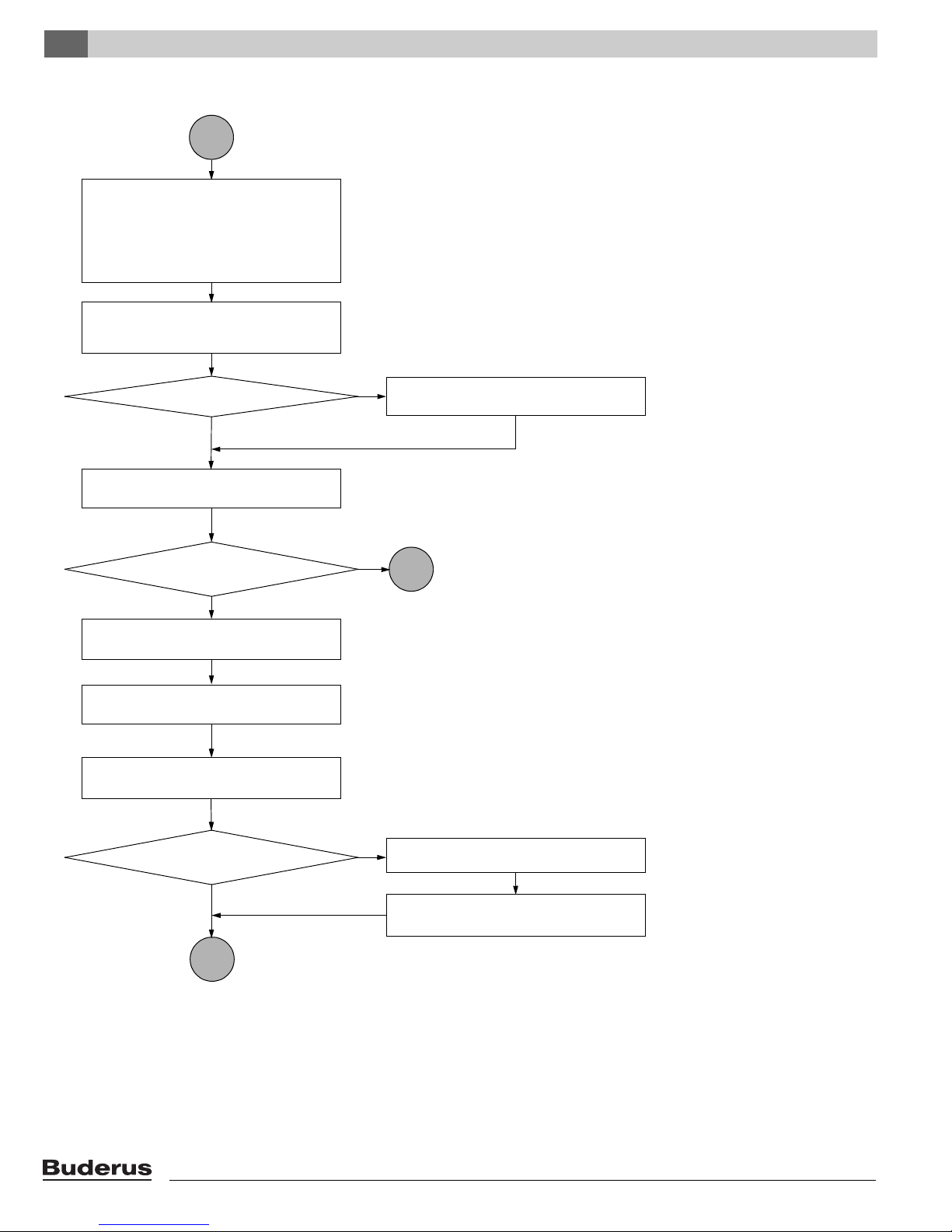
Function5
2
Has the pump post
purge time expired?
yes
yes
Have ten seconds
passed or was the power supply
interrupted?
yes
no
Operating code.
The boiler is in ready mode,
there is no heat request.
H
0
Start of pump post purge time via the heating
system. Pump post purge time in line with
"Settings" menu.
See page 12 and page 20.
Factory default setting: 5 minutes.
The primary circulation pump stops.
The primary circulation pump is run for
10 seconds to prevent it from seizing up.
no
page 15
3
page 17
no
Is
there a heat
request from the
room or outdoor
temperature-
dependent
regulator?
no
Is
the
temperature
in the hot water
tank at least
9 °F (5 K)lower than the
temperature set
on the BC10
or RC?
6
page 19
5
yes
yes
no
3
page 17
Is
there a heat
request from the
room or outdoor
temperature-
dependent
regulator?
Is
the
temperature
in the hot water
tank at least
9 °F (5 K) lower than
the temperature set
on the BC10
or RC?
6
page 19
yes
yes
no
3
page 17
Is
there a heat
request from the
room or outdoor
temperature-
dependent
regulator?
Is
the
temperature
in the hot water
tank at least
9 °F (5 K) lower than
the temperature set
on the BC10
or RC?
6
page 19
yes
yes
no
no
no
page 18
Has the primary
circulation pump been off for
more than 24 hours?
Logamax plus GB142-24/30/45/60 - We reserve the right to make any changes due to technical modifications!16
4
7
page 18
3
yes
Is the temperature
in the hot water tank higher
than the hot water temperature setting
in the BC10 or RC control
device?
no
H
L0
C0
The blower is started up.
The tank filling pump
is activated.
The hot surface ignitor is activated
for seven seconds.
The primary circulation pump
is started.
Ignition phase:
The gas valve is opened.
GB142 is in the hot water mode.
The "Burner" LED is lit.
The "Hot water mode" LED on the
BC10 is lit.
The "Hot water mode" LED
goes off.
yes
no
yes
no
page 16
The gas valve is closed,
the burner is shut down.
The "Burner" LED goes off.
The blower stops.
Is
the supply
temperature 82.8 K
higher than the hot water
temperature setting
or higher than
200 °F (93 °C)?
Is
the supply
temperature lower
than the preset
hot water temperature
plus 63 °F (35 K)?
page 19
Y0
Function 5
Logamax plus GB142-24/30/45/60 - We reserve the right to make any changes due to technical modifications! 17
Function5
5
Is there a
heat request from the room or
outdoor temperature-dependent
regulator?
yes
4
page 18
A0
The gas valve is closed,
the burner is shut down.
The "Burner" LED goes off.
Start the pump over-run time through the hot
water tank at least 30 seconds,
max. 1 minute, if there is a heat request.
Air-side after-purging by blower
for 30 seconds.
The blower stops.
The primary circulation pump stops.
The tank filling pump
is stopped.
no
6
page 19
page 16
H0
Logamax plus GB142-24/30/45/60 - We reserve the right to make any changes due to technical modifications!18
Is the
temperature in the hot water
at least 9 °F (5 K) lower than the temperature
set on the BC10 or RC?
6
Is the
room or outdoor temperature-
dependent regulator in the request
position?
no
yes
The GB142 enters heating mode.
The "Burner" LED is lit.
H
The "Heat request" LED goes off.
Is
the supply
temperature
11 °F (6 K) higher than
the target value? (The target value
is calculated by the outdoor
temperature-dependent regulator
or is set - in the event of room
temperature-dependent
regulation- on the
BC10)
5
H0
The gas valve is closed,
the burner is shut down.
The "Burner" LED goes off.
Start of pump post purge time via the heating
system. Pump post purge time in line with
"Settings" menu. See page 12 and page 20.
Factory default setting: 5 minutes.
Air-side after-purging by blower for
30 seconds.
The primary circulation pump stops.
page 16
The blower stops.
page 17
7
yes
no
The gas valve is closed,
the burner is shut down.
The "Burner" LED goes off.
The blower stops.
Is
the supply
temperature 11 °F (6 K)
lower than the
target value?
no yes
L0
C0
The blower is started up.
The hot surface ignitor is activated for
seven seconds.
The circulation pump is started up.
Ignition phase:
The gas valve is opened.
The "Heat request" LED is lit.
page 16, page 18
Yes
no
Y0
Function 5
Logamax plus GB142-24/30/45/60 - We reserve the right to make any changes due to technical modifications! 19
Symptoms6
6 Symptoms
6.1 Display indication on the BC10 basic controller
6.1.1 General
A display value or code is shown on the display of the BC 10 basic controller (see page 8, fig. 2).
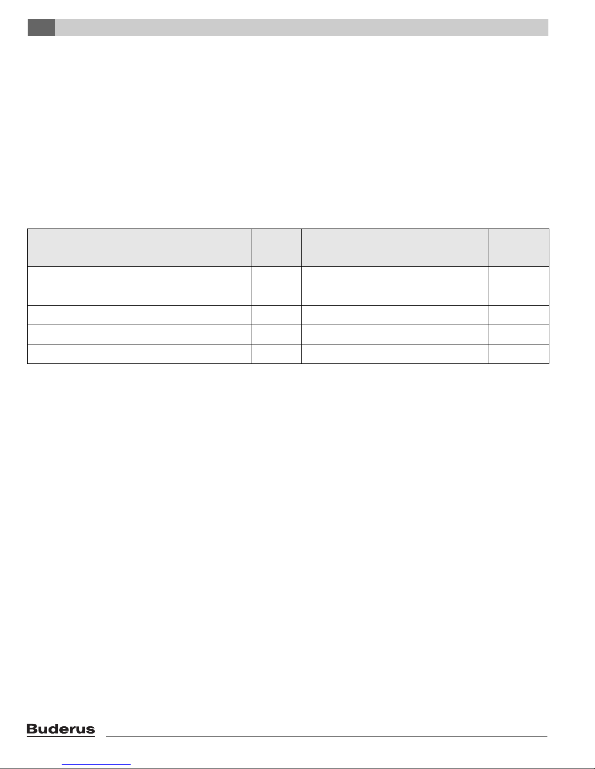
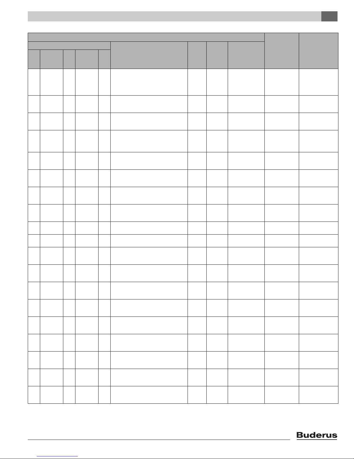
6.1.2 Display values on the display of the BC10 basic controller
The display value is shown automatically or can be called up by pressing the "Chimney sweep
page 10 and 12.
The following display values can be shown on the display of the BC10 basic controller:
Display
value
[\/7/2|
[p/2/9|
[l/9/9|
[f/\/5|
table 1 Display values on the BC10 basic controller
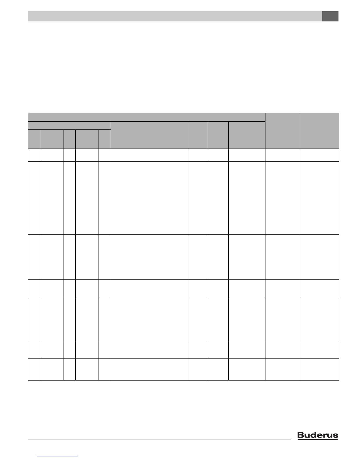
6.1.3 Display codes on the display of the BC10 basic
A display code shows the current status of the Logamax plus
GB142.
The display value is shown automatically or can be called up by
pressing the "Service
Two display codes (see table 2 level 3 and level 4) are shown.
After the first display code (level 3) is displayed, the second one
(level 4) can be called up by pushing the “Service
the BC10 basic controller level 4 can only be called up in the event
of a fault code.
Under normal operating conditions it is only possible to call up level
4 using the RC control device or a service tool.
Type of display value Unit Range
Current supply temperature °F
°C
Current heating system pressure psi
Configured target load %
Configured target pump post purge time min
controller
e" button.
e“ button. On
[\/\/0|
[-/1/8|
[p/0/0|
[l/3/0|
[f/0/0|
If the display code is a fault code, this fault code either flashes
(locked fault code) in the display or it is shown permanently
(blocking fault code). A boiler reset is only necessary with a
locking fault code (flashing) (see 8, fig. 2). The cause of the
fault must be remedied first. The cause has to be remedied
and the boiler resumes regular operation.
In the event of a locking boiler fault code both the display
value and the display code flash.
If there are more than once display codes at the same time,
the display codes will be shown in turn. And if one of these
display codes is a locking display code, the blocking display
codes shown will also flash.
–
[l/9/9|
–
–
–
–
d" or "Service e" button (see
Factory
default
setting
1)
/
[\/9/3|
[p/2/9|
[l/9/9|
[f/6/0|
/
/
[l/?/?| [l/?/?|
/
[f/1/d| [f/\/5|
Logamax plus GB142-24/30/45/60 - We reserve the right to make any changes due to technical modifications!20
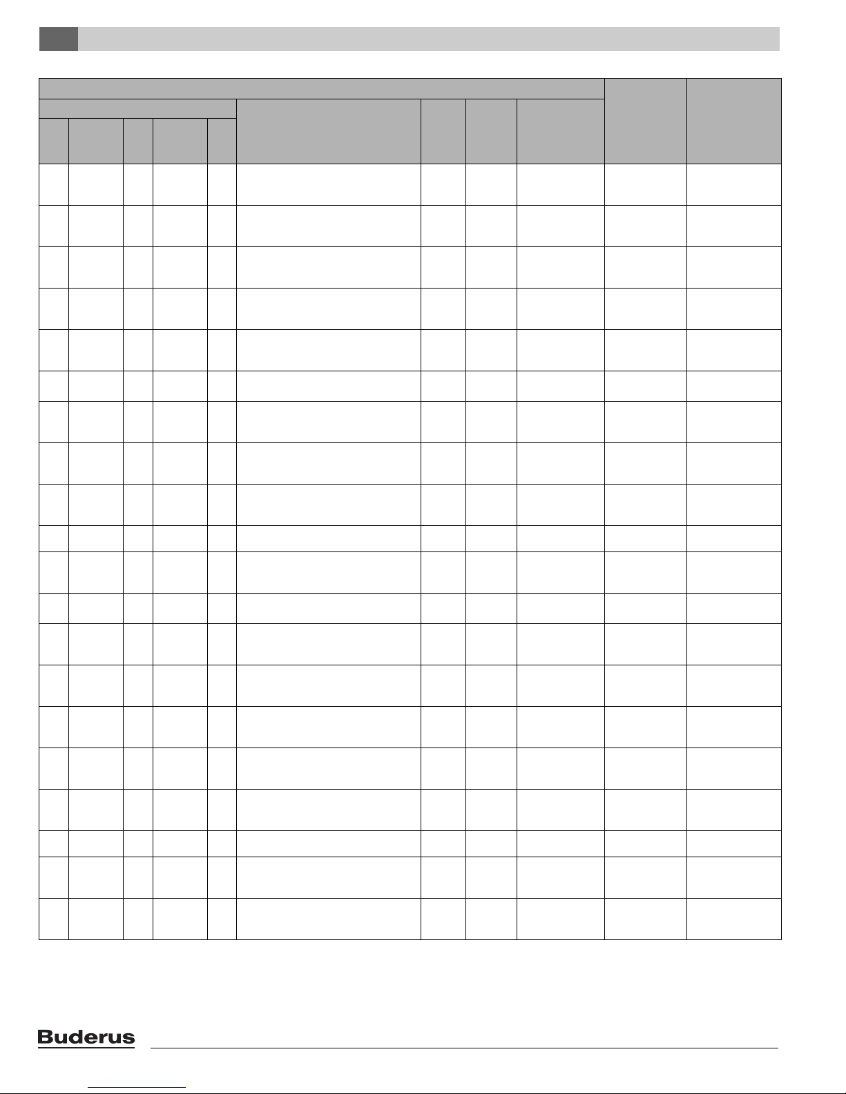
The following display values can be shown on the display of
the BC10 basic controller:
Abbreviations used in table 2:
Type of display code:
BC - Operating code
SC – Service code
BKS – Blocking boiler fault code
VKS – Locking boiler fault code (flashing)
AS – System fault code
ÜC – Other display codes
Symptoms
Display code
z
Main
display
code
z
Sub-
display
code
Key to display code
z
[\/\/\| [\/\/\|
[\/-/\|
e [-/a/\]
or any other
indication
with a
permanent
dot in the
bottom
right-hand
corner.
[2/0/8|
1)
e [-/h/\| e [2/0/0|
1)
e [-/h/}
any other
indication
with a
flashing dot
in the
bottom
right-hand
corner.
e [2/0/0|
1)
e [=/h/\| e [2/0/1|
1)
e [0/a/\| e [3/0/5|
1)
Communication test while starting up.
This code flashes 2 x 2 seconds while
starting up to indicate that the
communication between the UBA 3 and
the BC10 basic controller is being tested.
If a new UBA 3 or a new KIM was fitted,
this code will flash for
max. 10 seconds. If this code continues
to flash on the display, there is a fault in
the communication between the UBA 3
and the BC10 basic controller.
See page 46.
This fault code will also appear when
connecting a thermostat to the RC
terminals.
The boiler is in the flue gas test mode or
in service mode.
The boiler is in heating mode. BC
The boiler is in manual operation mode. BC The room
The boiler is in hot water mode. BC
The boiler has switched off. Start the
pump over-run time via the tank for at
least 30 seconds and maximum
1 minute.
table 2 Display indications on the BC10 basic controller
1)
only visible using the service tool
2)
is being carried out
Type of
display
code
ÜC No heating
BC page 10 or
BC
Reset
required
?
Other
symptoms
No indication in
display.
operation and no
hot water.
temperature is too
high.
Diagnosis Remedy
page 28 page 28
page 11
page 12 page 12
Symptoms 6
page 10 or page 11
Logamax plus GB142-24/30/45/60 - We reserve the right to make any changes due to technical modifications! 21

Symptoms6
Symptoms
Display code
Main
display
z
code
z
e [0/a/\| e [2/0/2|
e [0/c/\| e [2/8/3|
e [0/e/\| e [2/6/5|
e [0/h/\| e [2/0/3|
e [0/l/\| e [2/8/4|
e [0/u/\| e [2/7/0|
e [0/y/\| e [2/0/4|
e [0/y/\| e [2/7/6| e
e [0/y/\| e [2/7/7| e
e [0/y/\| e [2/8/5| e
table 2 Display indications on the BC10 basic controller
1)
only visible using the service tool
2)
is being carried out
Sub-
display
code
1)
1)
1)
1)
1)
1)
1)
Key to display code
z
Operating phase:
The switch optimization program is
activated.
This program is activated if there is more
than one burner firing requests from an
RC or ON/OFF regulator within 10
minutes.
This means that the boiler cannot be
restarted until at least ten minutes have
elapsed since initial startup of the burner.
The burner is started.
Readiness for operation:
The boiler is in ready mode.
The time-proportional program is
activated.
The time-proportional program is
activated as soon the load requested by
the modulating room controller is lower
than the lower limit of the boiler load.
During the time-proportional program the
burner is switched on and off repeatedly.
The period in which the burner is
switched on depends on the difference
between the load required by the
modulating room controller and the lower
limit of the boiler load. As soon as the
burner is switched on, the device is
operating at minimum load. As soon as
the burner is switched off, the display
code [0/e/\|
display of the BC10.
The time-proportional program is
deactivated automatically as soon as the
load required by the modulating room
controller is higher than the lower limit of
the boiler load.
The boiler is in ready mode, there is no
heat request.
The gas valve is opened.
Power Up.
Boiler is starting up after a reset or after
the main power is switched on.
This display code will be displayed for 4
minutes maximum.
The boiler switches off, the temperature
is higher than the target temperature.
The supply sensor has measured
a temperature higher than 203 °F
(95 °C).
The safety sensor has measured
a temperature higher than
203 °F (95 °C).
The return sensor has measured
a temperature higher than
203 °F (95 °C).
e [2/6/5| is indicated in the
Type of
display
code
BC Possibly no
BKS no
BKS no
BKS no
BC
BC
BC
BC
BC
BC
Reset
required
?
Other
symptoms
heating operation.
Diagnosis Remedy
Logamax plus GB142-24/30/45/60 - We reserve the right to make any changes due to technical modifications!22
Symptoms
Display code
Main
display
z
code
z
e [1/c/\| e [2/1/0| e
e [1/l/\| e [2/1/1| e
e [2/e/\| e [2/0/7| e
e [2/f/\| e [2/6/0|
e [2/f/\| e [2/7/1| e
e [2/l/\| e [2/6/6| e
e [2/p/\| e [2/1/2|
e [2/u/\| e [2/1/3|
e [3/a/\| e [2/6/4| e
e [3/f/\| e [2/7/3| e
e [3/l/\| e [2/1/4| e
e [3/p/\| e [2/1/6| e
e [3/y/\| e [2/1/5| e
e [4/a/\| e [2/1/8| e
e [4/c/\| e [2/2/4| e
e [4/e/\| e [2/7/8| e
e [4/l/\| e [2/2/0| e
e [4/p/\| e [2/2/1| e
e [4/u/\| e [2/2/2| e
Sub-
display
code
1)
1)
1)
Key to display code
z
Flue gas sensor is activated
(not available).
The UBA 3 does not register any
connections to the unused contacts 78
and 50.
The system pressure is too low.
No temperature increase after burner
start or the temperature difference
between the supply and safety sensors is
more than 27 °F (15 K).
The temperature difference between the
supply and safety sensors is more than
27 °F (15 K).
The primary circulation pump does not
generate a pressure difference.
Temperature increase of supply sensor
or safety sensor is more than 9 °F/sec
(5 K/sec).
The temperature difference between the
supply and return sensors is more than
90 °F (50 K).
The air flow by the blower has failed
during the operating phase.
The blower is switched off during the
safety test.
The blower is switched off during the
safety test.
The blower is running too slowly.
The blower is running too fast.
The supply sensor has measured a
temperature higher than 221 °F (105 °C).
The UBA 3 does not register the short cut
bestween the unused contacts 22 and
24.
The sensor test has failed.
The safety sensor is shorted or
measures temperatures higher than 266
°F (130 °C).
The safety sensor contact
is interrupted.
The supply sensor is shorted.
table 2 Display indications on the BC10 basic controller
1)
only visible using the service tool
2)
is being carried out
Type of
display
required
code
BKS no
BKS no
BKS no
BC
BKS no
VKS yes
BC
BC
BKS no
BKS no
VKS yes
VKS yes
VKS yes
VKS yes
VKS yes
VKS yes
VKS yes
VKS yes
VKS yes
Reset
?
Other
symptoms
Flue gas sensor
has measured a
flue gas temperature higher than
221 °F (105 °C)
No heating
operation and no
hot water.
No heating
operation and no
hot water.
No heating
operation and
no hot water.
No heating
operation and
no hot water.
No heating
operation and
no hot water.
No heating
operation and
no hot water.
No heating
operation and
no hot water.
No heating
operation and
no hot water.
No heating
operation and
no hot water.
No heating
operation and
no hot water.
No heating
operation and
no hot water.
No heating
operation and no
hot water.
Symptoms 6
Diagnosis Remedy
page 48 page 48
page 48 page 48
page 49 page 49
page 49 page 49
page 50 page 50
page 52 page 52
page 53 page 53
page 54 page 54
page 55 page 55
page 56 page 56
page 57 page 57
page 58 page 58
page 59 page 59
page 60 page 60
page 60 page 60
page 61 page 61
page 62 page 62
page 63 page 63
Logamax plus GB142-24/30/45/60 - We reserve the right to make any changes due to technical modifications! 23
Symptoms6
Symptoms
Display code
Main
display
z
code
z
e [4/y/\| e [2/2/3| e
e [6/a/\| e [2/2/7| e
e [6/a/\| e [2/2/7| e
e [6/c/\| e [2/2/8| e
e [6/c/\| e [3/0/6| e
e [6/l/\| e [2/2/9| e
e [6/p/\| e [2/6/9| e
e [7/c/\| e [2/3/1| e
e [7/l/\| e [2/6/1| e
e [7/l/\| e [2/8/0| e
e [8/y/\| e [2/3/2|
[8.8.8]
e [9/a/\| e [2/3/5| e
e [9/h/\| e [2/3/7| e
e [9/h/\| e [2/6/7| e
e [9/h/\| e [2/7/2| e
e [9/l/\| e [2/3/4| e
e [9/l/\| e [2/3/8| e
e [9/p/\| e [2/3/9| e
e [9/u/\| e [2/3/3| e
table 2 Display indications on the BC10 basic controller
1)
only visible using the service tool
2)
is being carried out
Sub-
display
code
1)
Key to display code
z
The supply sensor contact is interrupted.
No ionization after ignition.
After four startup attempts, a locking
boiler fault follows [6/a/\|.
No ionization after four startup attempts.
An ionization current was measured
before the burner start.
An ionization current was measured after
the burner switch-off.
Ionization fails during the operating
phase.
The hot surface ignitor activates too long.
The power supply was interrupted and
switched on again after a fault message.
The UBA 3 is defective.
The UBA 3 is defective.
The external switch contact is activated.
Display test while starting up. This code
is displayed for a maximum of 1 second.
KIM or UBA 3 is defective.
KIM or UBA 3 is defective.
The UBA 3 is defective.
The UBA 3 is defective.
The gas valve coil or the wiring to the gas
valve is defective.
The UBA 3 is defective.
KIM or UBA 3 is defective.
KIM or UBA 3 is defective.
Type of
display
required
code
VKS yes
BKS no
VKS yes
VKS yes
VKS yes
BKS no
VKS yes
VKS yes
VKS yes
VKS yes
BC
ÜC
VKS yes
VKS yes
VKS yes
VKS yes
VKS yes
VKS yes
VKS yes
VKS yes
Reset
?
Other
symptoms
No heating
operation and
no hot water.
No heating
operation and
no hot water.
No heating
operation and
no hot water.
No heating
operation and
no hot water.
No heating
operation and
no hot water.
No heating
operation and
no hot water.
No heating
operation and
no hot water.
No heating
operation and
no hot water.
No heating
operation and
no hot water.
No heating
operation and
no hot water.
No heating
operation and
no hot water.
No heating
operation and
no hot water.
No heating
operation and
no hot water.
No heating
operation and
no hot water.
Diagnosis Remedy
page 64 page 64
page 65 page 65
page 65 page 65
page 72 page 72
page 72 page 72
page 73 page 73
page 78 page 78
page 78 page 78
page 78 page 78
page 79 page 79
page 80 page 80
page 80 page 80
page 81 page 81
page 80 page 80
page 80 page 80
Logamax plus GB142-24/30/45/60 - We reserve the right to make any changes due to technical modifications!24
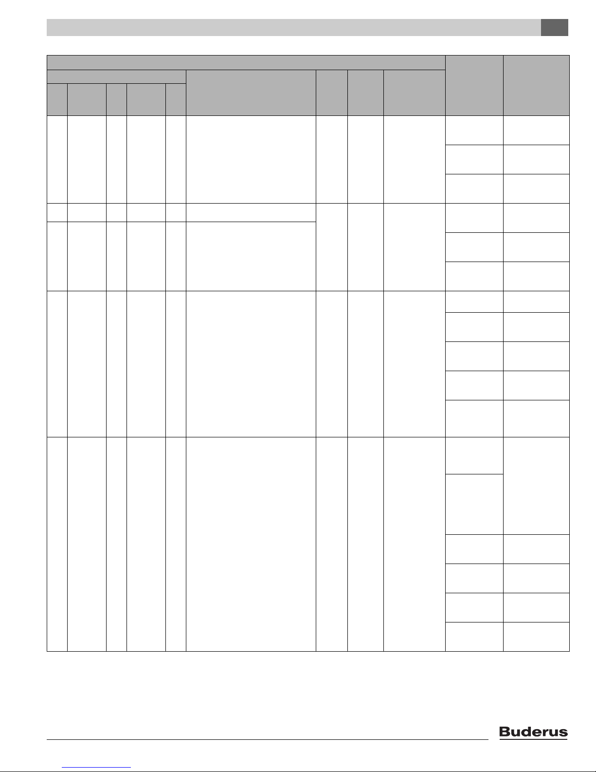
Symptoms
Display code
Main
display
z
code
z
e [a/0/1| e [8/0/0| e
e [a/0/1| e [8/0/8| e
e [a/0/1| e [8/0/9| e
e [a/0/1| e [8/1/0| e
e [a/0/1| e [8/1/1| e
Sub-
display
code
Key to display code
z
Outdoor sensor
Hot water temperature sensor
Hot water temperature sensor 2
Hot water remains cold.
Thermal disinfection.
table 2 Display indications on the BC10 basic controller
1)
only visible using the service tool
2)
is being carried out
Type of
display
code
AS
AS
AS
AS
Reset
required
?
Other
symptoms
The minimum
outdoor
temperature is
assumed.
No water is
heated any more.
The system
constantly tries to
heat the hot water
tank to the hot
water target value
setting.
The hot water
priority is
cancelled when
the fault message
appears.
Thermal
disinfection was
interrupted.
Symptoms 6
Diagnosis Remedy
Sensor
connected or
fitted incorrectly.
Sensor wire
broken or
shorted.
The sensor is
defective.
Sensor
connected or
fitted incorrectly.
Sensor wire
broken or
shorted.
The sensor is
defective.
Permanent
tapping or leak.
Sensor
connected or
fitted incorrectly.
Sensor wire
broken or
shorted.
The sensor is
defective.
Fill pump
connected
incorrectly or
defective.
Tap flow rate too
great during
disinfection
period.
Boiler load too
low for
simultaneous
heat use by
other connected
loads (e. g. 2nd
heating circuit).
Sensor
connected or
fitted incorrectly.
Sensor wire
broken or
shorted.
The sensor is
defective.
Fill pump
defective
Check the sensor
connection and the
sensor wire.
Check the sensor
installation.
Compare the
resistance value to
the sensor graph.
Check the sensor
connection and the
sensor wire.
Check the sensor
installation on the
hot water tank.
Compare the
resistance value to
the sensor graph.
Remedy the leak if
relevant.
Check the sensor
connection and the
sensor wire.
Check the sensor
installation on the
hot water tank.
Compare the
resistance value to
the sensor graph.
Test the fill pump
operation e. g.
using a relay test.
Choose the time for
thermal disinfection
so that no
additional heat
request occurs at
this time.
Check the sensor
connection and the
sensor wire.
Check the sensor
installation on the
hot water tank.
Compare the
resistance value to
the sensor graph.
Test the fill pump
operation e. g.
using a relay test.
Logamax plus GB142-24/30/45/60 - We reserve the right to make any changes due to technical modifications! 25

Symptoms6
Symptoms
Display code
Main
display
z
code
z
e [a/0/1| e [8/1/6| e
e [a/0/1| e [8/2/8| e
e [a/0/2| e [8/1/6| e
e [c/0/\| e [2/8/8| e
e [c/0/\| e [2/8/9| e
e [c/a/\| e [2/8/6| e
e [c/u/\| e [2/4/0| e
e [c/y/\| e [2/4/1| e
e [e/\/\|
+ any digit
or letter
e [e/\/\|
+ any digit
or letter
[h/\/7|
e [2/9/0| e
e [2/4/2|
e [h/\/7| e
[r/e/\|
table 2 Display indications on the BC10 basic controller
1)
only visible using the service tool
2)
is being carried out
Sub-
display
code
to
[2/8/7|
Key to display code
z
No communication with EMS.
Water pressure sensor.
No communication with BC10.
The UBA 3 has no connection to the
pressure sensor or there is a short circuit.
Short circuit in connection to pressure
sensor.
The return sensor has measured a
temperature higher than 221 °F (105 °C).
The return sensor is shorted.
The return sensor contact is interrupted.
The UBA 3 is defective.
KIM or UBA 3 is defective.
e
The heating system pressure is too low.
The heating system pressure is too low.
Reset is carried out. After pressing the
"Reset" button this code is displayed for
5 seconds.
Type of
display
required
code
AS
AS
AS
VKS yes
VKS yes
VKS yes
VKS yes
BKS no
VKS yes
SC
SC
ÜC
Reset
?
2)
Other
symptoms
The boiler no
longer gets heat
requests; the
heating system no
longer heats.
BC10 settings are
no longer taken
over by RCxx
devices.
No heating
operation and no
hot water.
No heating
operation and
no hot water.
No heating
operation and
no hot water.
Diagnosis Remedy
EMS bus system
is overloaded.
UBA 3/MC10 is
defective.
The digital water
pressure sensor
is defective.
Contact problem
at BC10 or BC10
is defective.
page 82 page 82
page 80 page 80
page 80 page 80
page 78 page 80
page 78 page 80
Reset by switching
the heating system
on and off.
Inform the
BUDERUS
customer service
department if
necessary.
Replace the digital
water pressure
sensor.
Check the BC10
connection.
Replace the BC10
if necessary.
6.2 LED on the UBA 3
In addition to the display indication on the BC10 basic controller, there is a red LED on the UBA 3.
The meaning of this LED is explained in see table 3.
LED Meaning
Off Normal operation
Flashing slowly (1 Hz) There is a boiler fault (locking fault).
Flashing fast (10 seconds) During startup after replacing the KIM or the UBA 3.
On During a fault in the UBA 3 or if the KIM is not recognized.
table 3 LED on the UBA 3
Logamax plus GB142-24/30/45/60 - We reserve the right to make any changes due to technical modifications!26

7 Diagnosis
7.1 Faults without a fault code
Hot water request
Although the UBA 3 indicates that the system is ready for
operation, it is possible that in the event of a hot water request no
hot water is made available, or it is only made available for a short
time.
Structure diagram for troubleshooting, see page 33.
Heating mode
Although the UBA 3 shows that the system is ready for operation
and the room temperature has not reached the preset value, the
Logamax plus GB142 does not enter the heating mode.
Structure diagram for troubleshooting: page 44.
Diagnosis 7
Logamax plus GB142-24/30/45/60 - We reserve the right to make any changes due to technical modifications! 27
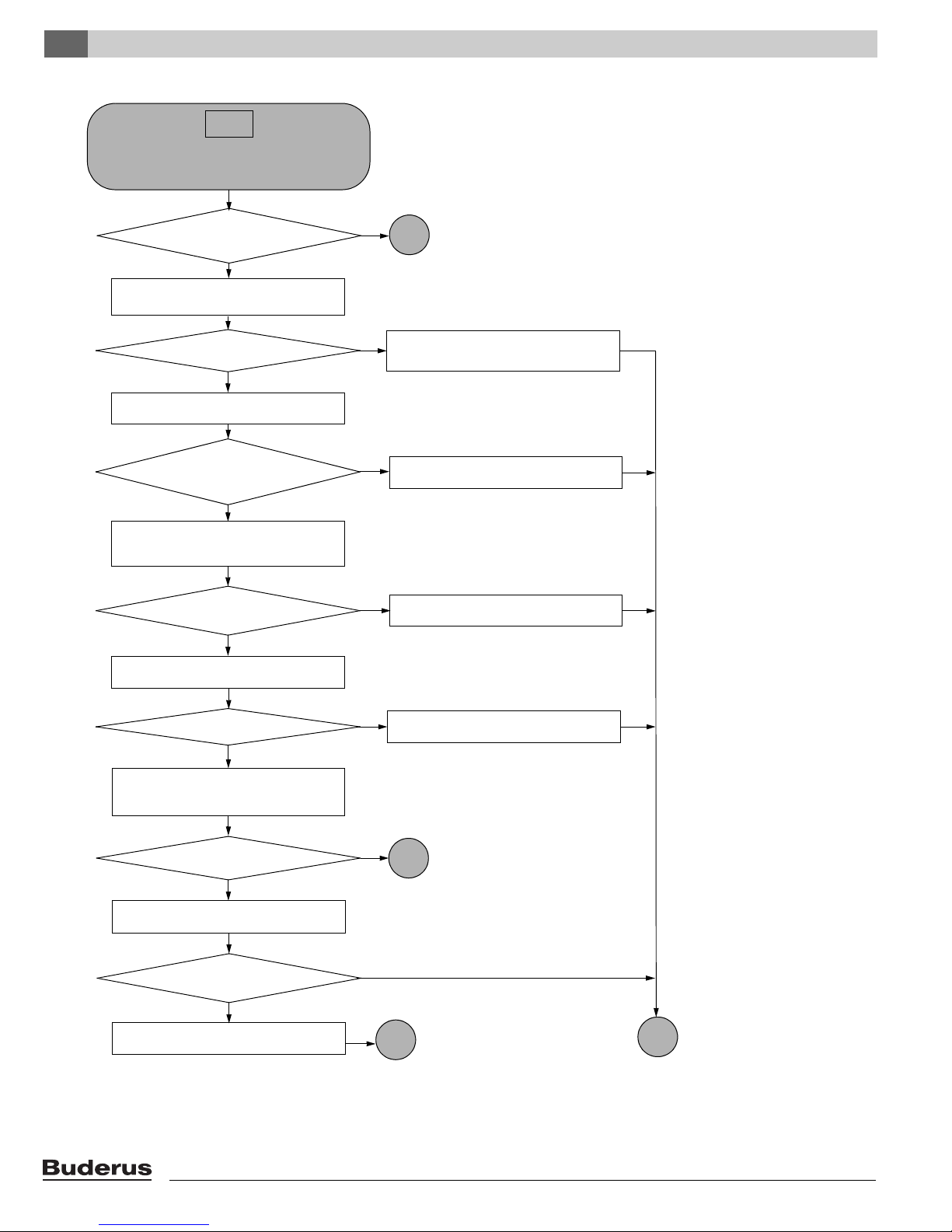
No display
8
page 31
yes
no
no
no
yes
Is the mains power
switch ON?
No indication in display.
no
yes
7
page 30
Switch on the mains power switch.
Check that the operating switch is in
position “1” (ON). See page 9.
yes
no
Is the
operating switch on the BC 10 in
position “1” (ON)?
Turn the operating switch on the BC 10 to
position “1” (ON). See page 9 (fig. 2).
Is the 120V AC cord okay?
Check that there is a 120V AC power
supply at the mains power switch.
yes
Is there a voltage at the
mains power switch?
Measure the resistance of the 120V AC
supply cord.
Check the fuse on the rear of the UBA 3
using a volt-ohm-multimeter.
See page 84.
Is the fuse okay?
44
page 83
Is there any indication on the
BC10 display?
Replace the fuse.
See page 84.
Deal with any problem in the electrical
system.
yes
no
Replace the cable loom (or the affected
part thereof.
Check that the mains power switch
is ON.
No
yes
Do the other
functions of the device work
normally?
19
page 29
Turn the operating switch on the BC10 to
position “0” (OFF). See page 9, par. 4.2.
Diagnosis7
Logamax plus GB142-24/30/45/60 - We reserve the right to make any changes due to technical modifications!28
44
page 83
Measure the relevant part of the cable loom.
See page 126.
Yes
Is the cable loom okay?
8
page 31
Check that there is between 7.8 and 15.2
VDC on both contacts 1 and 2 of the BC10.
See page 126.
No
No
Is there a voltage?
19
page 28
Replace the BC10.
See the fitting instructions of
the BC10.
Yes
Replace the cable loom or the
affected part thereof.
Diagnosis 7
Logamax plus GB142-24/30/45/60 - We reserve the right to make any changes due to technical modifications! 29
Diagnosis7
Replace the fuse again.
See page 84.
No
No
Yes
7
Disconnect the following boiler components
from the electrical power supply:
- the blower, see page 86,
- the primary circulation pump,
see page 126.
No
Yes
Is the fuse okay?
Is there any indication on the
BC10 display?
Connect the external primary
circulation pump.
10
page 31
Turn the operating switch on the BC 10 to
position “1” (ON). See page 9, par. 4.2.
Turn the operating switch
to “0” (OFF).
Is there any indication on the
BC10 display?
Turn the operating switch on the BC10 to
position “1” (ON). See page 9, par. 4.2.
Replace the external primary
circulation pump.
Replace the fuse again.
See page 84.
9
page 32
Check the fuse on the rear of the UBA 3
again using a volt-ohm-multimeter.
See page 84.
Yes
page 28
No display, part 2
Logamax plus GB142-24/30/45/60 - We reserve the right to make any changes due to technical modifications!30
 Loading...