

Buderus Logamax Plus GB142-24, Logamax Plus GB142-30, Logamax Plus GB142-45, Logamax Plus GB142-60 Installation Instructions Manual
Installation instructions
CAUTION!
Before putting the boiler into operation read this manual carefully.
WARNING!
Improper installation, adjustment, alteration, service or maintenance can
cause injury, loss of life or property damage. Refer to this manual. For
assistance or additional information consult a qualified installer, service
agency or the gas supplier.
CAUTION!
The operating manual is part of the documentation that is delivered to the
installation's operator. Go through the information in this manual with the
owner/operator and make sure that he or she is familiar with all the necessary operating instructions.
NOTICE!
In the Commonwealth of Massachusetts this boiler must be installed by a
licensed Plumber or Gas Fitter.
– Do not store or use gasoline or other flammable vapors and liquids in
the vicinity of this or any other boiler.
– What to do if you smell gas
• Do not try to light any boiler.
• Do not touch any electrical switch; do not use any phone in your
building.
• Immediately call your gas supplier from a neighbor’s phone. Follow
the gas supplier’s instructions.
• If you cannot reach your gas supplier, call the fire department.
–
Installation and service must be performed by a qualified
installer, service agency or the gas supplier.
Warning: If the information in these instructions is not
followed exactly, a fire or explosion may result causing property damage, personal injury or loss of life.
Condensing gas boiler
Logamax plus
GB142-24/30/45/60
For registered installers
Please read thoroughly
before installing servicing
7215 0200 (11/2012) US/CA

Preface
About these instructions
These Installation Instructions contain important information for the safe and professional installation, start-up and
maintenance of the boiler with boiler capacities 24, 30, 45
and 60 kW.
These Installation Instructions are intended for professional installers, who have the necessary training and
experience for working on heating and gas systems.
Subject to technical changes!
Slight changes may be made to the illustrations, process
steps and technical data as a result of our policy of
continuous improvement.
Updating of documentation
Please contact us if you have any suggestions for
improvements or corrections.
Logamax plus GB142-24/30/45/60 - We reserve the right to make any changes due to technical modifications!2
1 Safety and general instructions 5
1.1 Designated use 5
1.2 Hazard definitions 5
1.3 The following instructions must be observed 5
1.4 Observe these instructions for space heating
water 6
1.5 Tools, materials and additional equipment 6
1.6 Disposal 6
2 Regulations and guidelines 7
3 Product description 9
4 Dimensions and connections 10
5 Packaging and transportation 12
5.1 Scope of delivery 12
5.2 Transporting the boiler 12
Contents
8.13 Testing the Ignition Safety shut off device 38
8.14 Installing the casing 38
8.15 Informing the owner, handing over the technical
documents 38
9 BC10 basic controller 39
9.1 Operating the BC10 basic controller 39
9.1.1 Switching the heating system on and off 39
9.1.2 Displaying the operating conditions of the burner
and resetting the burner or resetting burner
faults 39
9.1.3 Displaying the heating system status and/or
faults 40
9.2 Carrying out additional tasks 42
9.2.1 Carrying out a flue gas test 42
9.2.2 Selecting partial load operation (e. g. during
flue gas testing) 42
9.2.3 Switching the heating system to manual mode 42
9.3 Configuring the boiler 43
9.3.1 Adjusting the heating capacity 43
9.3.2 Setting the DHW temperature value 44
9.3.3 Entering the space heating water temperature 44
9.3.4 Setting the pump post-purge period 45
6 Installation 13
6.1 Requirements for the installation room 13
6.2 Fitting the boiler 13
6.3 Making the gas connection 14
6.4 Fitting the heating circuit supply and return pipes 15
6.5 Combustion Air and Ventilation Openings 18
6.6 Installation of the flue gas adapter (included in
the scope of delivery) 20
6.7 Installation of the Exhaust and Air Intake system 21
6.8 Conversion to Propane 26
7 Electrical connections 27
7.1 External connection board connections 27
8 Start-up procedure 30
8.1 Testing for gas leaks 31
8.2 Filling the boiler 31
8.3 Filling the condensate trap 32
8.4 Bleeding the gas supply valve 32
8.5 Checking the combustion air/flue gas connection 32
8.6 Checking the orifices 33
8.7 Inlet gas pressure 33
8.8 Checking and adjusting the gas/air ratio 34
8.9 Carrying out a leak test in operating conditions 36
8.10 Measuring the carbon monoxide content (CO) 36
8.11 Function testing 36
8.12 Measuring the ionization current 37
10 Shutting down the system 46
10.1 Shut down the heating system using the
control unit 46
10.2 Shutting down the heating system in the event
of an emergency 46
11 Inspection 47
11.1 Preparing the boiler for inspection 47
11.2 Visual inspection for general signs of corrosion 47
11.3 Internal leak testing 48
11.4 Measuring the ionization current 48
11.5 Measuring the inlet gas pressure 48
11.6 Checking and adjusting the gas/air ratio 48
11.7 Carrying out a gas leak test in operating
conditions 48
11.8 Measuring the carbon monoxide content (CO) 48
11.9 Carrying out a pressure test of the heating
system 48
11.10 Checking the functioning and the safety of
the air intake and flue gas conduit 48
11.11 Checking venting systems 48
12 Maintenance 49
12.1 Cleaning the heat exchanger, burner and
condensate trap 49
12.2 Checking and adjusting the gas/air-ratio 51
Logamax plus GB142-24/30/45/60 - We reserve the right to make any changes due to technical modifications! 3
Contents
13 Appendix 52
13.1 Operating messages 52
13.2 Error messages 53
13.3 Technical specifications 54
14 Reports 56
14.1 Start-up report 56
14.2 Inspection report 57
14.3 Maintenance report 58
15 Spare parts 59
16 Index 63
Logamax plus GB142-24/30/45/60 - We reserve the right to make any changes due to technical modifications!4
1 Safety and general instructions
Safety and general instructions 1
Please observe these instructions in the interest of your
own safety.
1.1 Designated use
The boiler was designed for heating water for a central
heating system and generating domestic hot water.
The boiler is delivered with a BC10 basic controller and the
"Universal Automatic Burner Control Unit 3" (UBA 3)
pre-installed.
The boiler can be fitted with a modulating outdoor reset
control AM10 (scope of delivery), a room controller RC10
(optional), or an On/Off thermostat or relay panel end
switch (accessories).
1.2 Hazard definitions
The following defined terms are used throughout the documentation to bring attention to the presence of hazards of
various risk levels. Notices give important information
concerning the operation of the product.
DANGER:
Indicates the presence of hazards that will
cause severe personal injury, death or
substantial property damage.
WARNING:
Indicates the presence of hazards that can
cause severe personal injury, death or
substantial property damage.
CAUTION:
Indicates presence of hazards that will or
cause minor personal injury or property
damage.
CAUTION:
Risk of electric shock.
Indicates presence of hazards due to electric
shock.
NOTICE:
Indicates special instructions on installation,
operation or maintenance that are important
but not related to personal injury or property
damage.
1.3 The following instructions must be
observed
– The boiler must only be used for its designated
purpose, observing the Installation Instructions.
– Only use the boiler in the combinations and with the
accessories and spares listed.
– Other combinations, accessories and consumables
must only be used if they are specifically designed for
the intended application and do not affect the system
performance and the safety requirements.
– Maintenance and repairs must only be carried out by
trained professionals.
– You must report the installation of a condensing gas
boiler to the relevant gas utility company and have it
approved.
– You are only allowed to operate the condensing gas
boiler with the combustion air/flue gas system that has
been specifically designed and approved for this type of
boiler.
– Please note that local permission for the flue system
and the condensate water connection to the public
sewer system may be required.
You must also observe:
– the local building regulations stipulating the installation
rules.
– the local building regulations concerning the air intake
and outlet systems and the chimney connection.
– the regulations for the power supply connection.
– the technical rules laid down by the gas utility company
concerning the connection of the gas burner fitting to
the local gas main.
– the instructions and standards concerning the safety
equipment for the water/space heating system.
– the Installation Instructions for building heating
systems.
– The boiler must be located in an area where leakage of
the tank or connections will not result in damage to the
area adjacent to the boiler or to lower floors of the
structure. When such locations cannot be avoided, it is
recommended that a suitable drain pan, adequately
drained, be installed under the boiler. The pan must not
restrict combustion air flow.
– The boiler must be installed such that the gas ignition
system components are protected from water (dripping,
spraying, rain etc.) during boiler operation and service.
– The boiler must not be installed on carpeting.
– Do not restrict or seal any air intake or outlet openings.
– If you find any defects, you must inform the owner of the
system of the defect and the associated hazard in
writing.
Logamax plus GB142-24/30/45/60 - We reserve the right to make any changes due to technical modifications! 5
Safety and general instructions1
DANGER
if flammable gas explodes.
Beware if you smell gas: there may be an
explosion hazard!
Warning: If the information in these
instructions is not followed exactly, a fire
or explosion may result causing property
damage, personal injury or death.
Do not store or use gasoline or other flam-
mable vapors and liquids in the vicinity of
this or any other boiler.
What to do if you smell gas
Do not try to light any boiler.
Do not touch any electrical switch; do not
use any phone in your building.
Immediately call your gas supplier from
a neighbor’s phone. Follow the gas
supplier’s instructions.
If you cannot reach your gas supplier, call
the fire department.
Installation and service must be performed by
a qualified installer, service agency or the gas
supplier.
1.4 Observe these instructions for space
heating water
Unsuitable heating system water can promote the formation of scale or sludge, which affects system efficiency.
It can also cause corrosion and reduce life of the heat
exchanger.
– You must follow Buderus guidelines for boiler water
quality.
– Thoroughly flush the system prior to filling.
– Use of a Buderus approved boiler cleaner is
recommended.
– Never use salt bedding exchangers to soften the water.
– Do not use inhibitors or other additives unless approved
by Buderus for that purpose!
– When frost protection of the heating system is desired,
only use Buderus-approved Aluminum-safe antifreeze.
– When using oxygen-permeable pipes, e. g. for floor
heating systems, you must separate the system using
heat exchangers.
– The maximum permissible flow rate of the
GB142-24/30 this is 11 GPM (gal./min.)(= 42 l/min.), for
the GB142-45 is 15 GPM (= 57 l/min.) and for the
GB142-60 is 20 GPM (= 76 l/min.).
1.5 Tools, materials and additional
equipment
For the installation and maintenance of the boiler you will
need the standard tools for space heating, gas and water
fitting.
In addition, a handtruck with a fastening belt is useful.
1.6 Disposal
– Dispose of the boiler packaging in an environmentally
sound manner.
– Dispose of components of the heating system (e. g.
boiler or control device), that must be replaced in an
environmentally responsible manner.
Logamax plus GB142-24/30/45/60 - We reserve the right to make any changes due to technical modifications!6

2 Regulations and guidelines
Regulations and guidelines 2
The installation must conform to the requirements of the
authority having jurisdiction or, in the absence of such
requirements, to the latest edition of the National Fuel Gas
Code, ANSI Z223.1. In Canada, installation must be in
accordance with the requirements of CAN/CSA B149.1,
Natural Gas and Propane Installation Code.
Where required by the authority having jurisdiction, the
installation must conform to the Standard for Controls and
Safety Devices for Automatically Fired Boilers, ANSI/
ASME CSD-1.
Install CO detectors per local regulations. Boiler requires
yearly maintenance, see maintenance section see
chapter 12 "Maintenance", page 49.
Operating Limits of the boiler:
Max. boiler temperature: 230 °F (110 °C)
Max. operating pressure: 44
The hot water distribution system must comply with all
applicable codes and regulations. When replacing an
existing boiler, it is important to check the condition of the
entire hot water distribution system to ensure safe operation.
Massachusetts Installations Only:
(a) For all side wall side horizontally vented gas fueled
equipment installed in every dwelling, building or structure
used in whole or in part for residential purposes, including
those owned or operated by the Commonwealth and
where the side wall exhaust vent termination is less than
seven (7) feet above finished grade in the area of the
venting, including but not limited to decks and porches, the
following requirements shall be satisfied:
1. INSTALLATION OF CARBON MONOXIDE
DETECTORS. At the time of installation of the side
wall horizontal vented gas fueled equipment, the
installing plumber or gasfitter shall observe that a hard
wired carbon monoxide detector with an alarm and
battery back-up is installed on the floor level where the
gas equipment is to be installed. In addition, the
installing plumber or gasfitter shall observe that a
battery operated or hard wired carbon monoxide
detector with an alarm is installed on each additional
level of the dwelling, buiding or structure served by the
side wall horizontal vented gas fueled equipment. It
shall be the responsibility of the property owner to
secure the services of qualified licensed proffesionals
for the installation of hard wired carbon monoxide
detectors.
psi (3 bar)
a. In the event that the side wall horizontally vented
gas fueled equipment is installed in a crawl space
or an attic, the hard wired carbon monoxide
detector with alarm and battery back-up may be
installed on the next adjacent floor level.
b. In the event that the requirements of this
subdivision can not be met at the time of
completion of installation, the owner shall have a
period of thirty (30) days to comply with the above
requirements; provided, however, that during said
thirty (30) day period, a battery operated carbon
monoxide detector with an alarm shall be installed.
2. APPROVED CARBON MONOXIDE DETECTORS.
Each carbon monoxide detector as required in
accordance with the above provisions shall comply
with NPA 720 and be ANSI/UL 2034 listed and
IAS certified.
3. SIGNAGE. A metal or plastic identification plate shall
be permanently mounted to the exterior of the building
at a minimum height of eight (8) feet above grade
directly in line with the exhaust vent terminal for the
horizontally vented gas fueled heating appliance or
equipment. the sign shall read, in print size no less
than one-half (½) inch in size, “GAS VENT DIRECTLY
BELOW. KEEP CLEAR OF ALL OBSTRUCTIONS”.
4. INSPECTION. The state or local gas inspector of the
side wall horizontally vented gas fueled equipment
shall not approve the installation unless, upon
inspections, the inspector observes carbon monoxide
detectors and signage installed in accordance with the
provisions of 248 CRM 5.08(2)(a)1 through 4.
(b) EXEMPTIONS: The following equipment is exempt
from 248 CRM 5.08(2)(a)1 through 4:
1. The equipment listed in Chapter 10 entitled
“Equipment Not Required To Be Vented” in the
most currect edition of NFPA 54 as adopted by the
board: and
2. Product Approved side wall horizontally vented gas
fueled equipment installed in a room or structure
separate from the dwelling, building or structure
used in whole or in part for residential puposes.
Logamax plus GB142-24/30/45/60 - We reserve the right to make any changes due to technical modifications! 7

Regulations and guidelines2
(c) MANUFACTURERS REQUIREMENTS - GAS EQUIPMENT VENTING SYSTEM REQUIRED.
When the manufacturer of Product Approved side wall horizontally mounted gas equipment provides a venting system
design or venting system components with the equipment,
the instructions provided by the manufacturer for the installation of the equipment and venting shall include:
1. Detailed instructions for the installation of the venting
system or the venting system components: and
2. A complete parts list for the venting system design or
venting system.
(d) MANUFACTURERS REQUIREMENTS - GAS EQUIPMENT VENTING SYSTEM NOT PROVIDED.
When the manufacturer of Product Approved side wall horizontally vented gas fueled equipment does not provide the
parts for the venting of flue gases, but identifies “special
venting systems”, the following requirements shall be satisfied by the manufacturer:
1. The referenced “special venting systems” shall be
included with the appliance or equipment installation
instructions: and
2. The “special venting systems” shall be Product
Approved by the Board, and the instructions for that
system shall include a parts list and detaild
installation instructions.
(e) A copy of all instructions for all Product Approved side
wall horizontally vented gas fueled equipment, all venting
instructions, all parts lists for venting instructions, and/or
venting design instructions shall remain with the appliance
or equipment at the completion of the installation.
Logamax plus GB142-24/30/45/60 - We reserve the right to make any changes due to technical modifications!8
3 Product description
1
2
3
9
11
13
14
9
16
15
5
8
1
4
10
12
13
14
2
3
5
4
6
7
9
11
9
8
10
12
16
15
17
7
6
190
170
150
130
90
110
140
130
120
90
100
110
4
7
2
1
5
812
1011
3 6
9
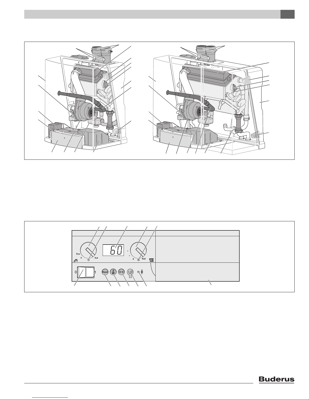
Product description 3
Fig. 1 Logamax plus GB142-24/30 (left) and GB142-45/60 (right)
pos. 1: Drawer with control unit
2: Universal Burner Automat (UBA3)
3: Control unit BC10
4: Gas valve
5: Cover
6: Flue measuring points
7: Parallel flue
8: Burner
Fig. 2 Basic Controller Logamatic BC10
pos. 1: Main switch
2: DHW temperature knob
3: LED "DHW status"
4: Display
5: Space heating water temperature knob
6: LED "Heating system status"
1) ECO mode means that the temperature inside the hot water tank is 140 °F (60 °C), with a hysteresis (T) of 18 °F (10 °C) instead of 9 °F (5 °C)
1)
7: Under the cover a RC system controller can be installed
8: LED "Burner Operation"
9: Service Tool connector
10: "Service"
11: "Chimney sweep"
12: "Reset"
9: Latches of which two have locks
10: Sighting glass
11: Heat exchanger
12: Back cover
13: Air intake for the fan
14: Fan
15: Condensate trap and internal condensate drain flue gas pipe
16: External Connection Board (under the cover)
17: Pressure sensor
e button
d button
c button
Logamax plus GB142-24/30/45/60 - We reserve the right to make any changes due to technical modifications! 9
Dimensions and connections4
4" (100 mm)
12" (300 mm)
20" (500 mm)
6.2"
(158 mm)
0.25"
(6 mm)
1.8" (46 mm)
18.7" (475 mm)
> 6"
(150 mm)
2.2" (55 mm)
3" (75 mm)
3" (75 mm)
6" (150 mm)
1.2" (30 mm)
16" (420 mm)
7.5" (190 mm)
28" (712 mm)
5.5" (239 mm)
4.3" (110 mm)13.2" (335 mm)
22" (560 mm)
3" (75 mm)
> 4"
(100 mm)
6" (150 mm)
DE FG
AB
C
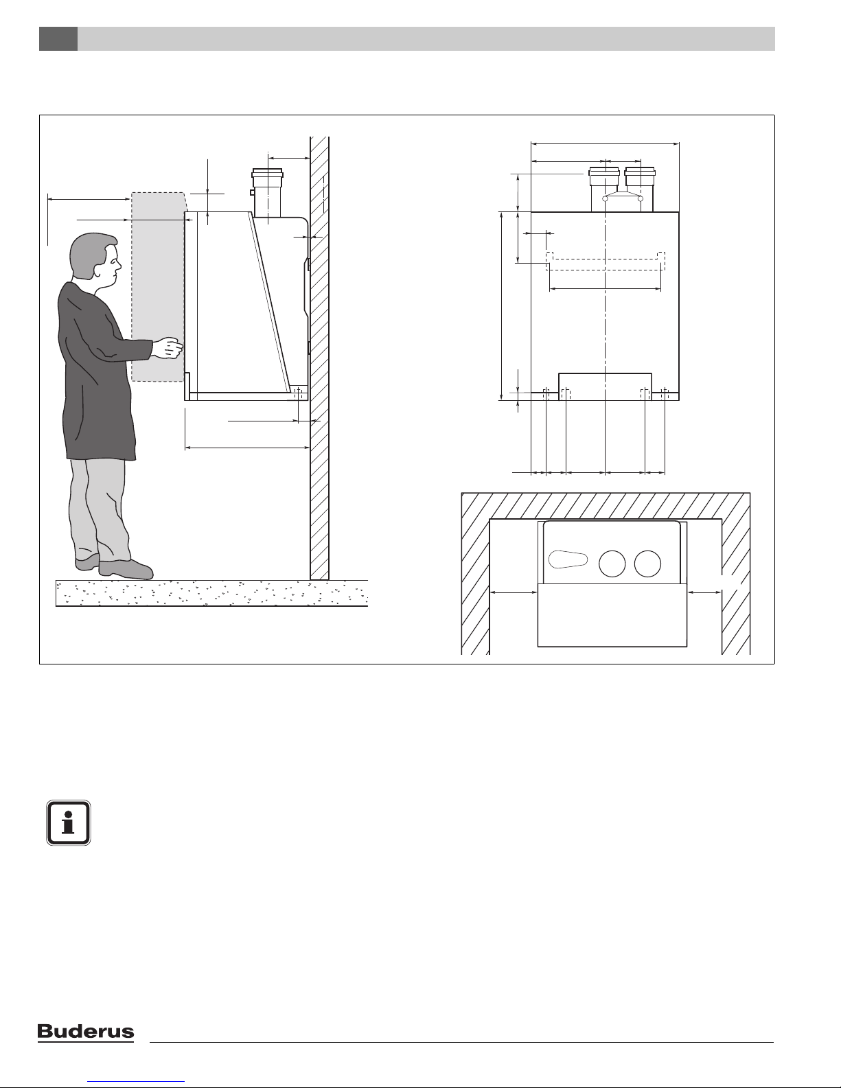
4 Dimensions and connections
Fig. 3 Dimensions and connections for boiler GB142-24/30 (dimensions in inches)
Flue gas connection (inside diameter 3'')
AA (A)
AKO (E)
GAS (D)
=
Condensate water outlet, Ø 1.3” (Ø 32 mm) outside
=
diameter
=
Gas connection, ¾” NPT
1
One Ø 1.0” (Ø 25.4 mm) inside x 1'' NPT threaded compression fitting is delivered enclosed with boiler packaging
NOTICE
Observe the lateral minimum distances of the
boiler (12” = 300 mm) and the necessary
distances (24” (600 mm) at the front and
LA (B)
RK (G)
VK (F)
WB (C)
=
=
=
=
Air intake (inside diameter 3'')
Return, Ø 1.0”
Supply, Ø 1.0”
Wall bracket
4” (100 mm) at the top) for removing the casing
and for servicing.
Closet clearances are:
4” (100 mm) to the right, 4” (100 mm) at the top
and 6” (150 mm) to the left.
1
(Ø 25.4 mm)
1
(Ø 25.4 mm)
Logamax plus GB142-24/30/45/60 - We reserve the right to make any changes due to technical modifications!10
Dimensions and connections 4
20.7" (526 mm)
1.2" (30 mm)
16" (420 mm)
7.5" (190 mm)
28" (712 mm)
5.5" (239 mm)
4.3" (110 mm)
13.2" (335 mm)
35.4" (900 mm)
9.7" (246 mm)
6.2"
(158 mm)
0.25"
(6 mm)
1.8" (46 mm)
18.7" (475 mm)
> 6"
(150 mm)
> 4"
(100 mm)
2.2" (55 mm)
3" (75 mm)
3" (75 mm)
DE F G
AB
C
4" (100 mm)
12" (300 mm)
20" (500 mm)
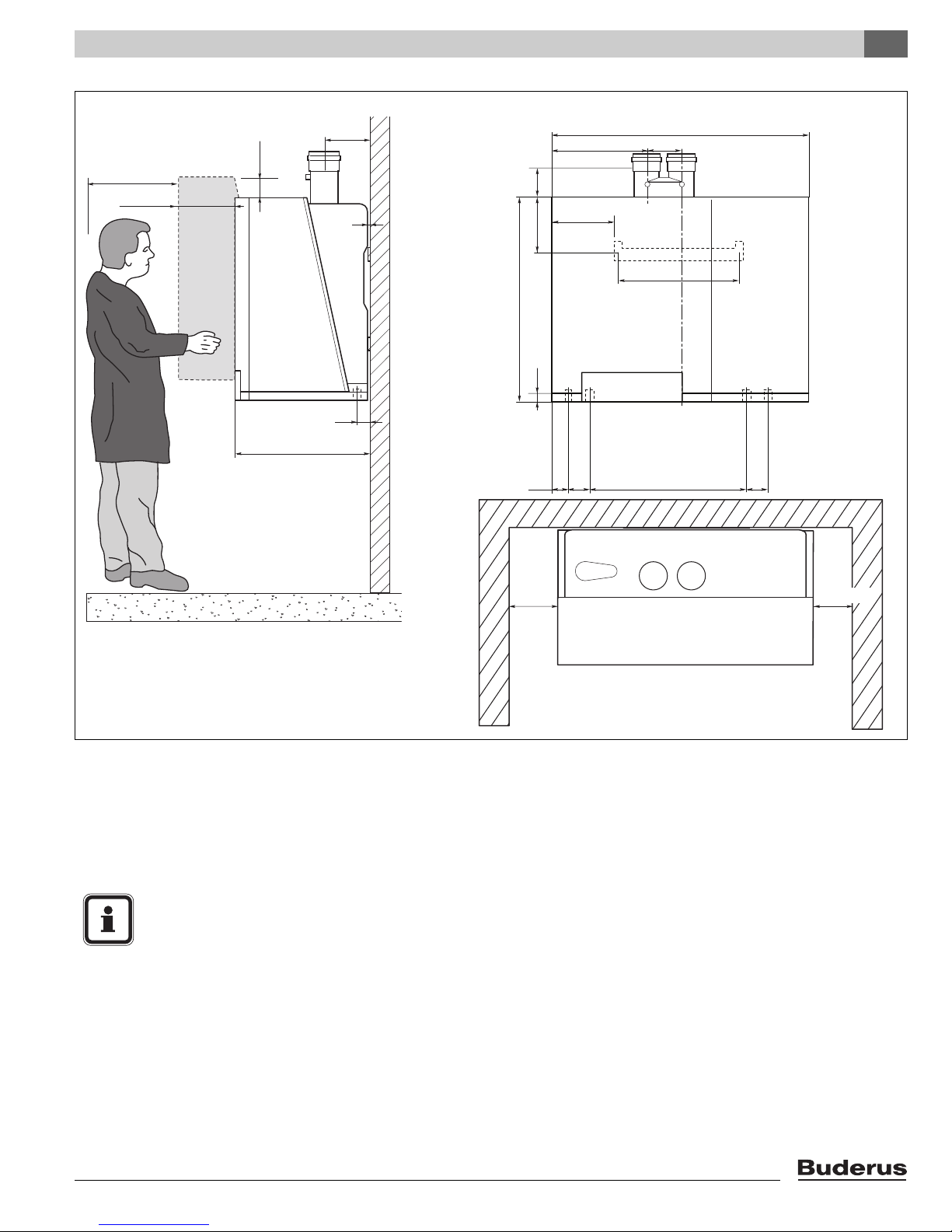
Fig. 4 Dimensions and connections for boiler GB142-45/60 (dimensions in inches)
Combustion air
AA (A)
AKO (E)
GAS (D)
1
One Ø 1.0” (Ø 25.4 mm) inside x 1'' NPT threaded compression fitting is delivered enclosed.
=
Condensate water outlet, Ø 1.3” (Ø 32 mm)
=
Gas connection, ¾” NPT
=
LA (B)
RK (G)
VK (F)
WB (C)
=
=
=
=
NOTICE
Observe the lateral minimum distances of the
boiler (12” = 300 mm) and the necessary
distances (24” (600 mm) at the front and
4” (100 mm) at the top) for removing the casing
and for servicing.
Closet clearances are:
4” (100 mm) to the right, 4” (100 mm) at the top
and 6” (150 mm) to the left.
Air intake
Return, Ø 1.0”
Supply, Ø 1.0”
Wall bracket
1
(Ø 25.4 mm)
1
(Ø 25.4 mm)
Logamax plus GB142-24/30/45/60 - We reserve the right to make any changes due to technical modifications! 11
Packaging and transportation5
1
2
6
8
4
3
7
9
5
5 Packaging and transportation
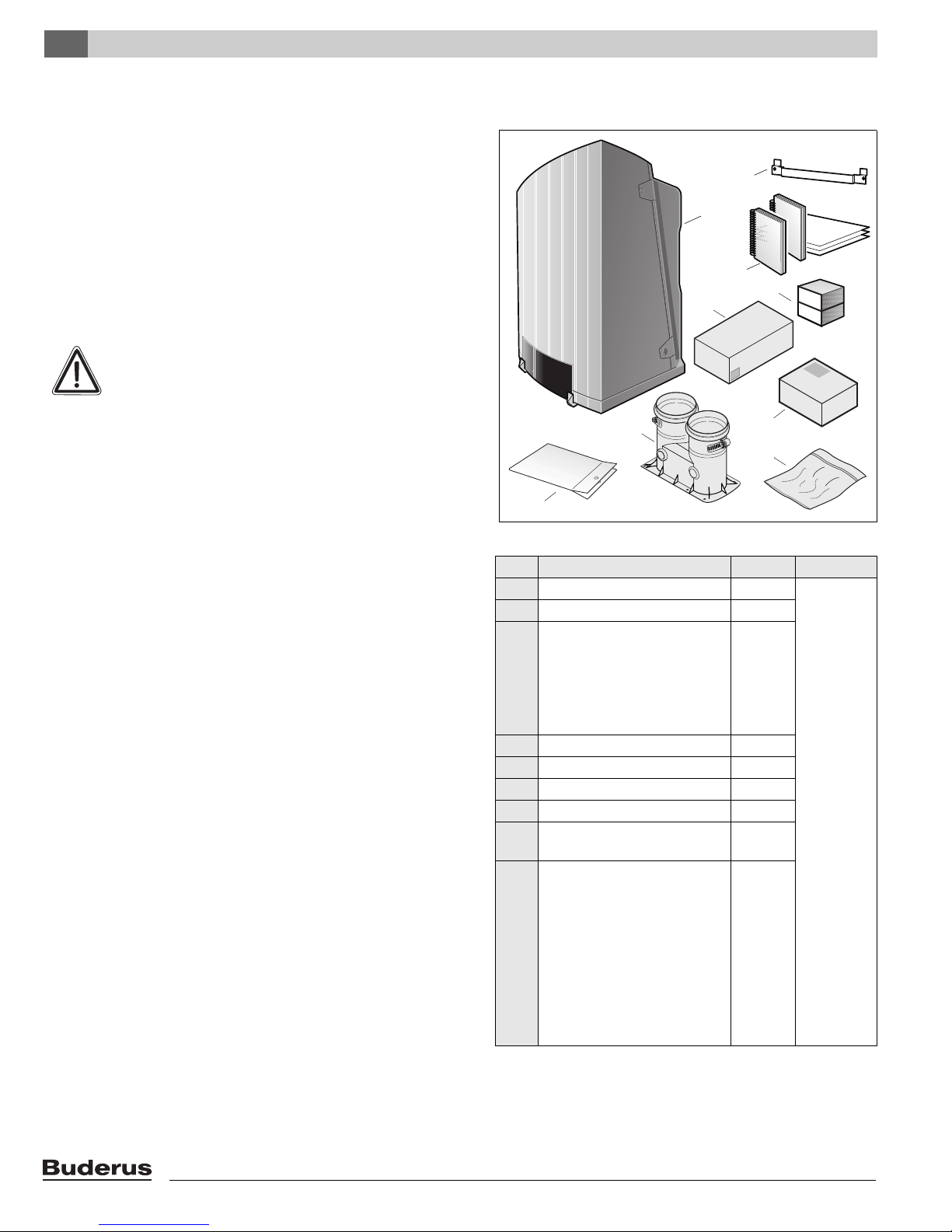
5.1 Scope of delivery
The boiler is delivered fully assembled.
When receiving the delivery, check if the packaging is
intact.
Check that all the items listed in see table 1 are included
in the delivery.
5.2 Transporting the boiler
CAUTION
The boiler may be damaged when it is improperly secured.
– Only transport the boiler using the right
transportation equipment, such as a
handtruck with a fastening belt or special
equipment for manoeuvering steps.
– During transportation the boiler must be
secured on the transportation equipment to
prevent it from falling off.
– Protect all parts against impacts if they are to
be transported.
– Observe the transportation markings on the
packaging.
Packaged boilers must always be lifted and carried to
their destination by two people, or you must use a
handtruck or special equipment to transport them to their
destination.
Transport the boiler to the room where it is to be installed.
Fig. 5 Items supplied with unit
Pos. Parts Quantity Packaging
1 Boiler with casing 1 1 box
2 Wall bracket 1
3 Technical documents
including:
- User's Instructions
- Installation Instructions
- wall mounting template
- Servicing Instructions
4 Compression fittings 2
5 AM10 with outdoor sensor 1
6 Flue gas adapter 1
7 Propane conversion kit 1
8 Boiler connection kit,
including the DHW sensor
9 GB142 Boiler manifold
including:
- low loss header
- pressure relief valve
- tridicator
- DHW connections
- Grundfos 15-58 3-speed
boiler circulator
- supply and return shutoff ball
valves
Table 1 Items supplied with unit
1
The user’s instructions (in a special format) is located in the boiler
drawer
1
3
1
1
Logamax plus GB142-24/30/45/60 - We reserve the right to make any changes due to technical modifications!12

6 Installation
6.1 Requirements for the installation room
DANGER
– Install the heating system in a frost-free
room.
– Do not store any flammable materials or
liquids in the immediate vicinity of the boiler.
– Never use any chlorinated detergents or
halogenated hydrocarbons (e. g. in
spraycans, solvents and detergents, paints,
adhesives).
– Do not allow too much dust to collect on the
boiler.
6.2 Fitting the boiler
Observe the installation clearances of the combustion air/
flue gas system.
Installation 6
NOTICE
– To protect the connection orifice you must
not remove the styrofoam bottom panel.
– Do not lift the boiler by the drawer.
– Do not remove the transport safety clamps
(see fig. 6) from the drawer at this time.
– Protect the boiler and the combustion
air/flue gas orifice against pollution during
installation.
Remove the packaging materials and dispose of them.
Use the mounting template to mark the drill holes.
Install the wall bracket taking into account the necessary
service clearances.
Remove the transport safety clamps (fig. 6).
Fig. 6 Removing the transport safety clamps
Logamax plus GB142-24/30/45/60 - We reserve the right to make any changes due to technical modifications! 13
Installation6
1
2
2
2
2
3
1
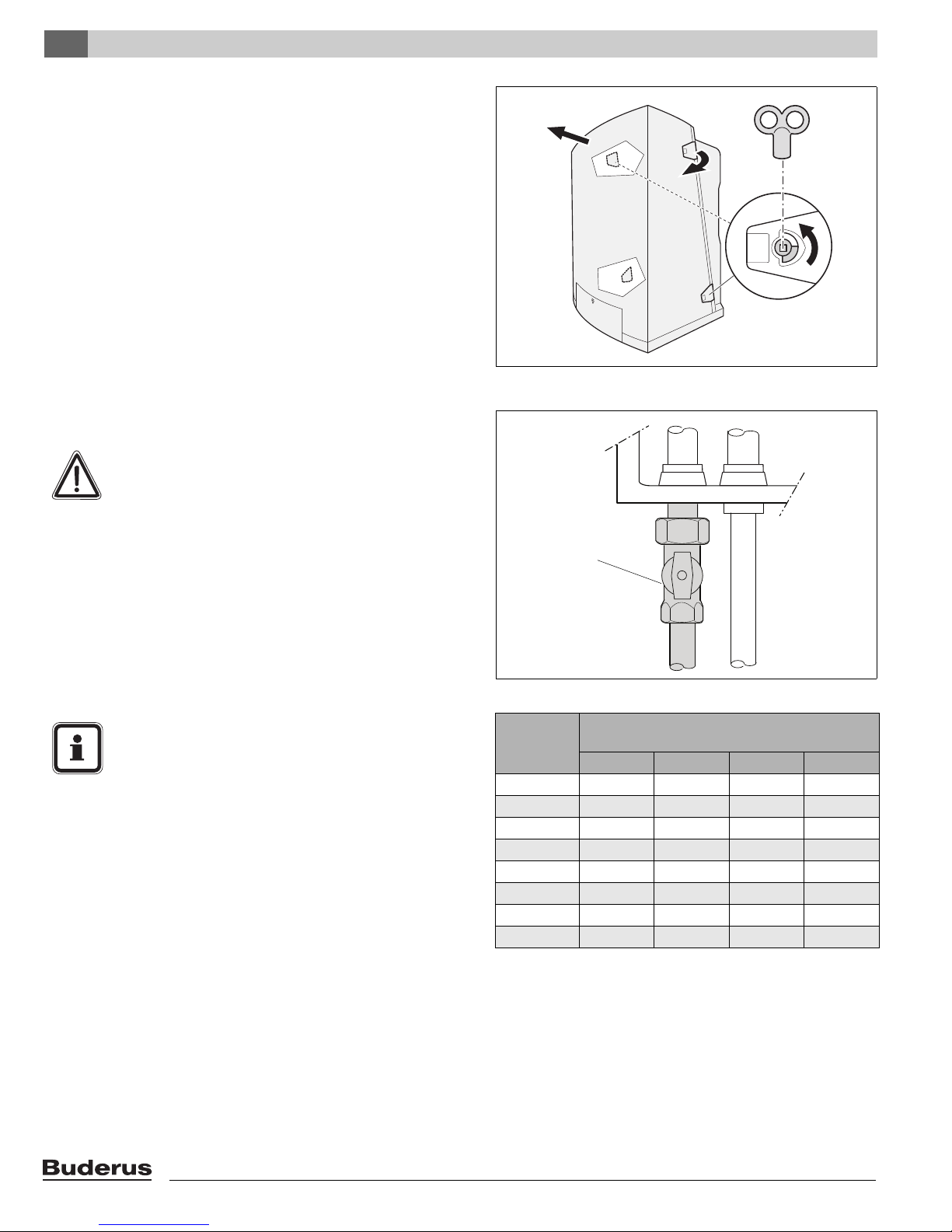
Use the radiator key to unlock the two latches a quarter
turn (fig. 7, pos. 1).
Open the latches (fig. 7, pos. 2).
Remove the casing by lifting it upwards and then pulling
it forwards (fig. 7, pos. 3); do not hold the casing by the
latches.
Hold the boiler by the rear boiler casing and place it on
the wall bracket.
Level out the boiler.
6.3 Making the gas connection
DANGER
Only carry out work on gas lines if you are
licensed for such work.
Fig. 7 Removing the casing
Determine proper size gas pipe for the installation using
see table 2 and see table 3. Do not forget the pipe fitting
losses and observe proper size of the fittings.
Install the furnished ¾” gas cock on the gas connection.
Connect the gas pipe to the gas cock (fig. 8, pos. 1) so
that it is free from any strain.
NOTICE
When installing the gas supply connection, it
must comply with local regulations or, if such
regulations do not exist, with the National Fuel
Gas Code, ANSI Z 223.1.
In Canada, the gas supply connection must
comply with local regulations or, if such regulations do not exist, with CAN/CSA B149.1,
Natural Gas and Propane Installation Code.
A sediment trap must be provided upstream of the gas
controls.
Fig. 8 Making the gas connection
Length of
pipe (feet)
¾" 1" 1 ¼" 1 ½"
10 278 520 1,060 1,600
20 190 350 730 1,100
30 152 285 590 890
40 130 245 500 760
50 115 215 440 670
75 93 175 360 545
100 79 160 305 480
150 64 120 250 380
Table 2 Gas Pipe Capacity for different pipe sizes
1 Maximum pipe capacity in ft3/hr, based on a specific gravity of
.60 (42 mbar) and a inlet gas pressure of 14 inches W.C.
(35 mbar) or less and a pressure drop of .3 inches W.C. (20 mbar)
Gas Volume Capacity
(ft3 / hr)
1
Logamax plus GB142-24/30/45/60 - We reserve the right to make any changes due to technical modifications!14
Installation 6
6.4 Fitting the heating circuit supply and
return pipes
NOTICE
– To protect the entire heating system we
require installing a WYE strainer in the return
circuit. When retrofitting the boiler to an
existing heating system this filter is required.
– Install shut-off valves immediately before and
after the dirt particle filter to allow the filter to
be cleaned.
Steel pipe
diameter
in inches
¾ 2.1 4.1 0.5 1.25
1 2.6 5.2 0.6 1.60
1 ¼ 3.5 6.9 0.8 2.15
1 ½ 4.0 8.0 0.9 2.50
Table 3 Equivalent length for pipe fittings in feet
Equivalent length for Pipe Fittings in feet
Type of pipe fitting
90°-Elbow Tee
(flow thru
branch)
Equivalent length in feet
Gate valve Gas cocks
1
11
3
2
11
4
Fit a filling and drain cock in the heating system supply
pipe if required.
Also fit an adequately sized safety valve in the system
that meets all applicable codes and regulations.
NOTICE
When using oxygen-permeable pipes, e. g. for
radiant floor heating systems, you must separate the system using heat exchangers.
Buderus recommends hydraulically isolating
snowmelt systems using heat exchangers.
Thoroughly flush all pipes and radiators. Use of a
Buderus approved boiler cleaner is recommended.
Refer to the installation template for the pipe connection
dimensions.
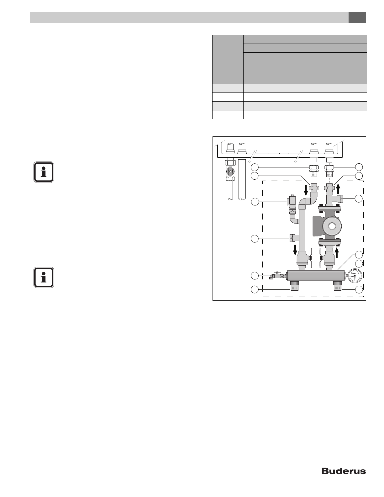
Fit the compression fittings (fig. 9, pos. 1 and 2) first to
the Hydronic set (see fig. 10, 11 and 12) and then to the
boiler.
Connect the expansion tank to the system.
Connect the pipes so that they are free from strain.
Connecting boiler with DHW tank
Connect the external hot-water tank according to the
Installation instructions of the hot-water tank and fittings
concerned.
5
8
9
Fig. 9 Pump manifold installation
pos. 1: Compression fitting (heating system supply pipe)
2: Compression fitting (heating system return pipe)
3: Relief valve
4: DHW return 1“FPT
5: DHW supply 1“FPT
6: Low loss header
7: System return 1½ MPT
8: Drain valve
9: System supply 1½ MPT
10: Tridicator
11: Di electric union
6
10
7
Logamax plus GB142-24/30/45/60 - We reserve the right to make any changes due to technical modifications! 15
Installation6
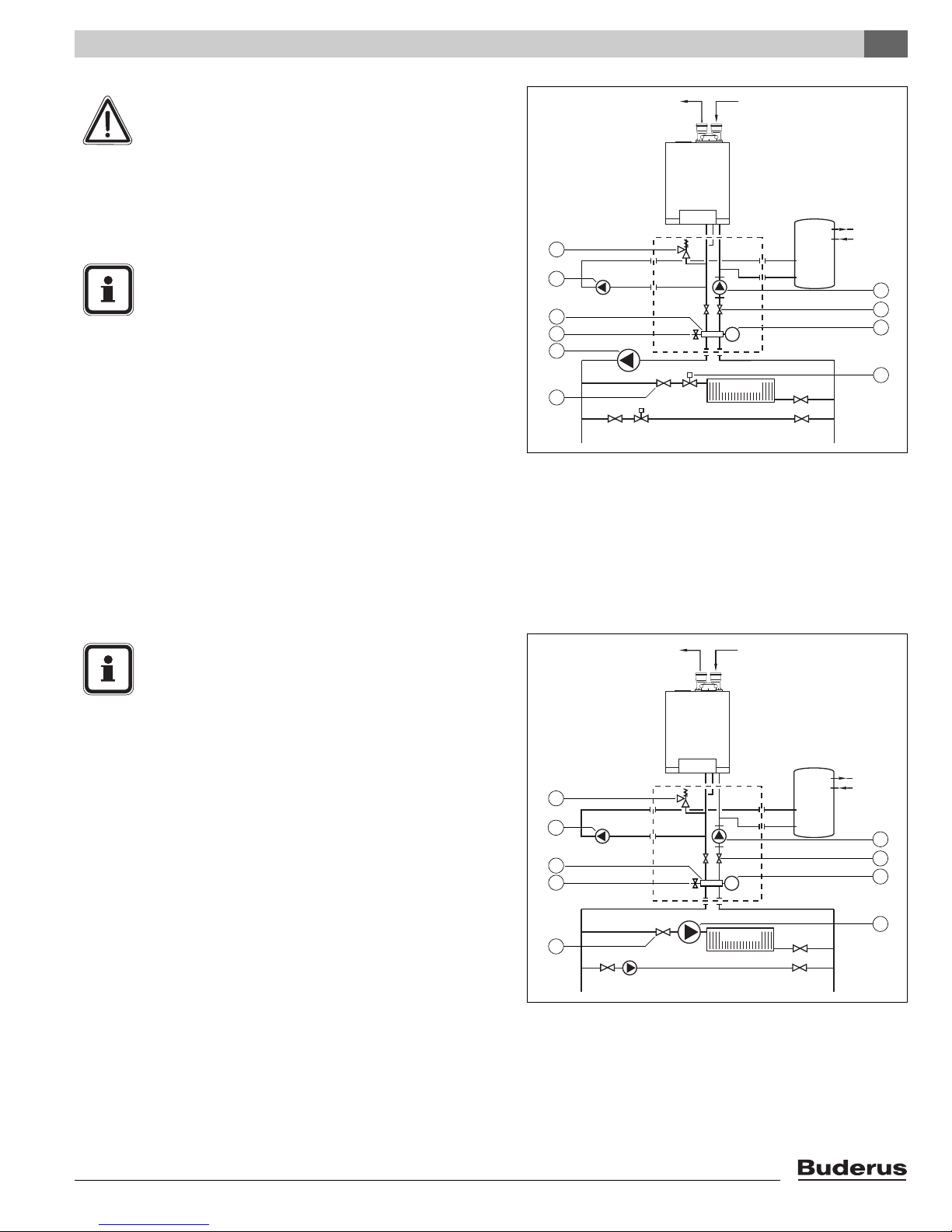
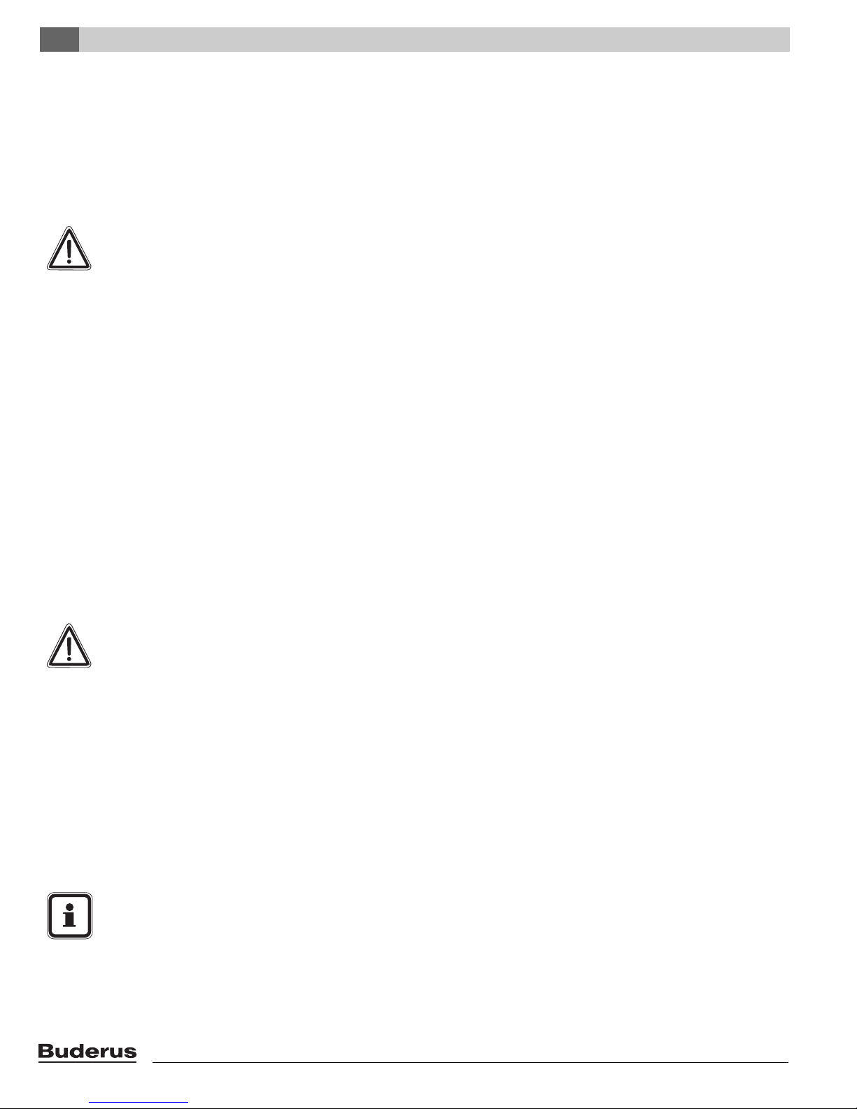
Piping examples
The following illustrations are two Installation examples.
NOTICE
The following illustrations are simplified conceptual illustrations only.
FLUE GAS AIR INTAKE
Piping and field components must be field verified.
A hot water boiler installed above radiation level or as
required by the Authority having jurisdiction, must be
provided with a low water cutoff device either as a part of
the boiler or at the time of boiler installation.
Fig. 10 is a schematic representation of fig. 9.
NOTICE
If this boiler is installed in a closed water supply
system with an external indirect DHW tank,
such as one having a backflow preventer in the
cold water supply line, means shall be provided
to control thermal expansion. Contact the water
supplier or local plumbing inspector on how to
control this situation.
Relief valve
The indirect DHW tank must have a temperature and pressure relief valve installed. The
relief valve shall comply with the Standard for
Relief Valves and Automatic Gas Shutoff
Devices for Hot Water Supply Systems, ANSI
Z21.22-CSA 4.4.
Install the relief valve according fig. 10.
The relief valve must comply with following
specifications:
– dimensions: height 2¼ inch (57.15 mm),
width 2 inch (50.8 mm).
– 30 Psi (2 bar) discharge pressure.
– discharge is ¾ inch (19.1 mm) female in
diameter.
GB142GB142
pump manifold
2
1
3
5
PT
7
Fig. 10 Schematic representation of the boiler with the hydronic set
pos. 1: DHW supply 1“FPT
2: DHW return 1“FPT
3: pump manifold shut-off valve
4: Low loss header
5: drain valve
6: PT gauge (pressure and temperature gauge)
7: System supply 1½ MPT
8: System return 1½ MPT
4
6
8
Logamax plus GB142-24/30/45/60 - We reserve the right to make any changes due to technical modifications!16
Installation 6
WARNING
No valve is to be placed between the relief valve
and the tank. Discharge of the relief valve must
be conducted to a suitable place for disposal
when relief occurs and no reducing coupling or
other restriction may be installed in the
discharge line.
NOTICE
For the maximum permissible flow rate of the
DHW pump see §1.4 (page 6)
FLUE GAS
GB142GB142
1
3
5
7
AIR INTAKE
PT
Optional
Additional
DHW
DHW
Tank
Tank
2
4
6
9
8
10
zones
Radiant
Aditional zones
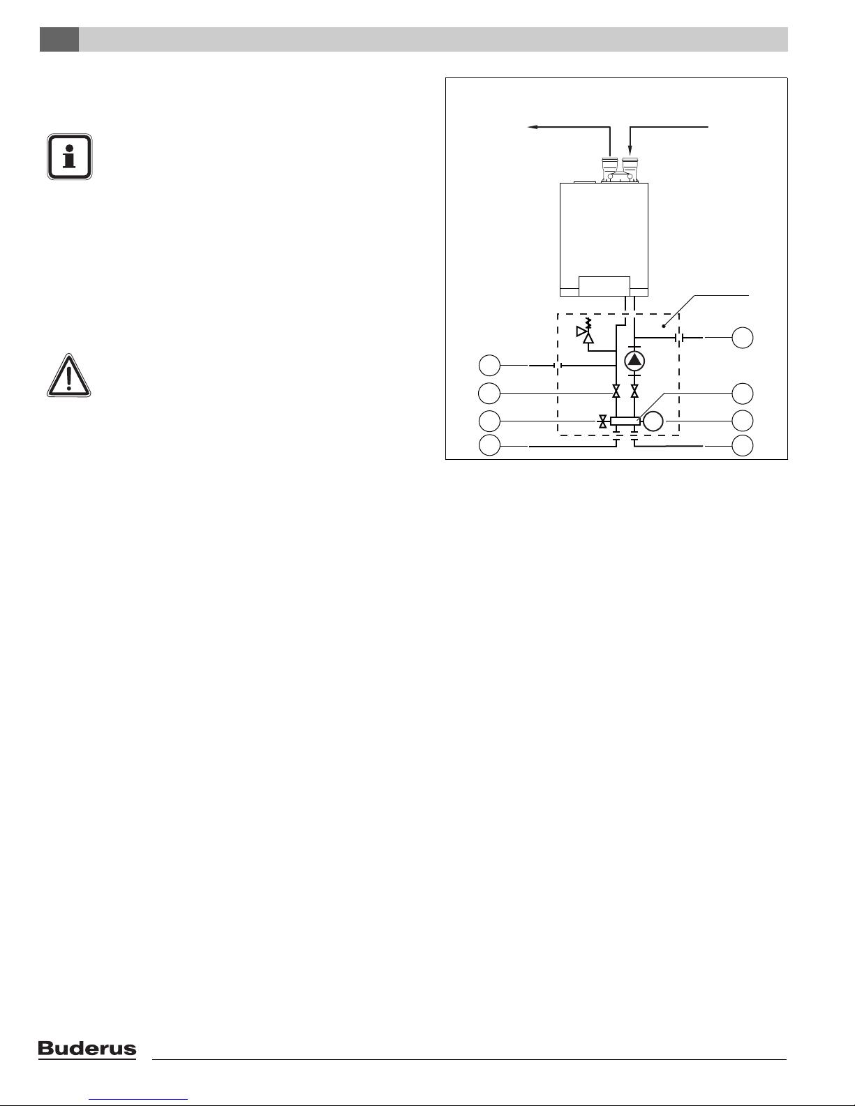
Fig. 11 Schematic representation of the boiler with the hydraulic set
connected to an optional hot water tank with one or multiple
zones including one pump and zone valves
1: pressure relief valve
2: primary pump
3: DHW pump
4: Shut-off valve
7: drain valve
8: zone valve
9: secondary pump
10: shut-off valve
5: Low los header
6: PT gauge (pressure and
temperature gauge)
NOTICE
Primary boiler pump must have an internal
check valve.
FLUE GAS
GB142GB142
1
AIR INTAKE
Optional
Additional
DHW
DHW
Tank
Tank
3
5
7
zones
9
Aditional zones
PT
Radiant
Fig. 12 Schematic representation of the boiler with the
Hydronic set connected to an optional hot water tank
with one or multiple zones and zone pumps
1: pressure relief valve
2: primary pump
3: DHW pump
4: shut-off valve
5: Low loss header
6: PT gauge (pressure and
temperature gauge)
7: drain valve
8: zone pump
9: shut-off valve
2
4
6
8
Logamax plus GB142-24/30/45/60 - We reserve the right to make any changes due to technical modifications! 17
Installation6
6.5 Combustion Air and Ventilation
Openings
Provisions for combustion and ventilation air must be made
in accordance with section 5.3, Air for Combustion and
Ventilation, of the National Flue Gas Code, ANSI Z223.1, or
Sections 7.2, 7.3 or 7.4 of CAN/CGA B149, Installation
Codes, or applicable provisions of the local building codes.
CAUTION:
BOILER DAMAGE AND OPERATIONAL
FAILURES !
Due to insufficient or lacking openings for
combustion air and/or ventilation of the boiler
room.
Provisions for combustion air and ventilation are
always required, regardless whether the
combustion air is taken from the outside (sealed
combustion) or inside (non sealed combustion
for combustion).
Insufficient ventilation of the boiler room can
lead to high air temperatures. This can result in
boiler damage.
– Make sure that intake and exhaust openings
are sufficiently sized and no reduction or
closure of openings takes place.
– When the problem is not resolved, do not
operate the boiler.
– Please note these restrictions and its
dangers to the operator of the boiler.
WARNING:
BOILER DAMAGE !
due to contaminated air.
– Boiler must be clear and free from
combustible materials, gasoline and other
flammable vapors and liquids, and corrosive
liquids and vapors.
Never use chlorine and hydrocarbon
containing chemicals (such as spray
chemicals, solution and cleaning agents,
paints, glues etc) in the vicinity of the boiler.
– Do not store and use these chemicals in the
boiler room.
– Avoid excessive dust formation and build-up.
NOTICE
When one expects contaminated combustion
air (near swimming pools, chemical cleaning
operations and hair salons), sealed combustion
operation is recommended.
Logamax plus GB142-24/30/45/60 - We reserve the right to make any changes due to technical modifications!18
DANGER:
FIRE DANGER !
due to flammable materials or liquids.
– Do not store flammable materials and liquids
in the immediate vicinity of the boiler.
All Air from Inside the Building (non sealed combustion)
The closet shall be provided with two permanent openings
communicating directly with an additional room(s). The total
input of all gas utilization equipment installed in the
combined space shall be considered in making this determination. Each opening shall have a minimum free area of
1 square inch per 1,000 Btu per hour of total input rating of
all gas utilization equipment in the confined space, but no
less than 100 square inches. One opening shall commence
within 12 inches (305 mm) of the top, and one opening shall
commence within 12 inches (305 mm) of the bottom of the
enclosure. The minimum dimension of air openings shall be
not less than 3 inches (75 mm).
1. Where directly communicating with the outdoors, each
opening shall have a minimum free area of 1 square
inch per 4,000 Btu/hr of total input rating of all
equipment in the enclosure.
2. Where communicating with the outdoors through
vertical ducts, each opening shall have a minimum free
area of 1 square inch per 4,000 Btu/hr of total input
rating of all equipment in the enclosure.
3. Where communicating with the outdoors through
horizontal ducts, each opening shall have a minimum
free area of 1 square inch per 2,000 Btu/hr of total input
rating of all equipment in the enclosure.
4. Where ducts are used, they shall be of the same crosssectional area as the free area of the opening to which
they connect.
Installation 6
Logamax plus GB142-24/30/45/60 - We reserve the right to make any changes due to technical modifications! 19
Installation6
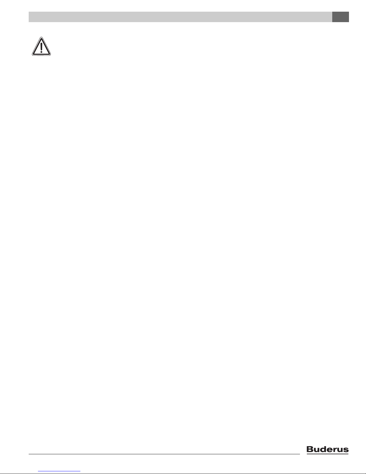
6.6 Installation of the flue gas adapter
(included in the scope of delivery)
Before installing the exhaust and air intake system, it is
necessary to remove the transport safety device and to
install the flue gas adapter.
NOTICE
The transport safety device has been installed
to prevent unwanted movement of the heat
exchanger during transport.
Remove the transport safety device with the two screws
(see fig. 13).
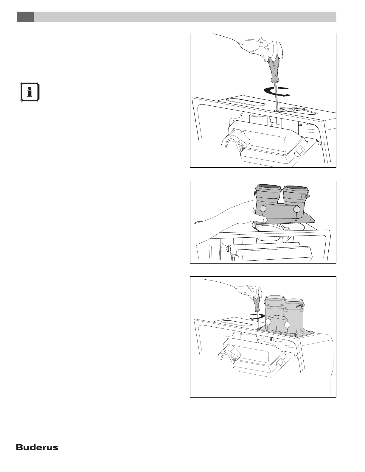
Remove the protective cap from the internal condens
bypass pipe. Place the flue gas adapter and connect the
internal condens bypass pipe (see fig. 14).
Fig. 13 Removing the transport safety device
Screw on the flue gas adapter using six screws (see
fig. 15).
Fig. 14 Placing the flue gas adapter
Fig. 15 Connecting the flue gas adapter
Logamax plus GB142-24/30/45/60 - We reserve the right to make any changes due to technical modifications!20
 Loading...