

Buderus Logamax plus Installation Instructions Manual
Installation instructions
CAUTION!
Before putting the boiler into operation read this manual carefully.
WARNING!
Improper installation, adjustment, alteration, service or maintenance can cause
injury, loss of life or property damage. Refer to this manual. For assistance or additional information consult a qualified installer, service agency or the gas supplier.
CAUTION!
The operating manual is part of the documentation that is delivered to the installation's operator. Go through the information in this manual with the owner/operator
and make sure that he or she is familiar with all the necessary operating instructions.
NOTICE!
In the Commonwealth of Massachusetts this boiler must be installed by a licensed
Plumber or Gas Fitter.
Warning: If the information in these instructions is not followed
exactly, a fire or explosion may result causing property
damage, personal injury or loss of life.
– Do not store or use gasoline or other flammable vapors and liquids in the
vicinity of this or any other appliance.
– What to do if you smell gas
• Do not try to light any boiler.
• Do not touch any electrical switch; do not use any phone in your
building.
• Immediately call your gas supplier from a neighbor’s phone.
Follow the gas supplier’s instructions.
• If you cannot reach your gas supplier, call the fire department.
– Installation and service must be performed by a qualified installer,
service agency or the gas supplier.
Condensing gas boiler
7 746 800 103 (09/2009) US/CA
Notice:
• This manual is available in the English and French language.
• This manual must be retained for future reference.
Logamax plus
GB162-80 kW/100 kW
For the registered installer
Please read these
instructions carefully
before starting the
operation
Product description
Product description
15
20
19
18
10
11
14
13
12
8
7
17
15
21
22
23
24
25
269
27
28
29
30
31
32
16
5
6
34 2
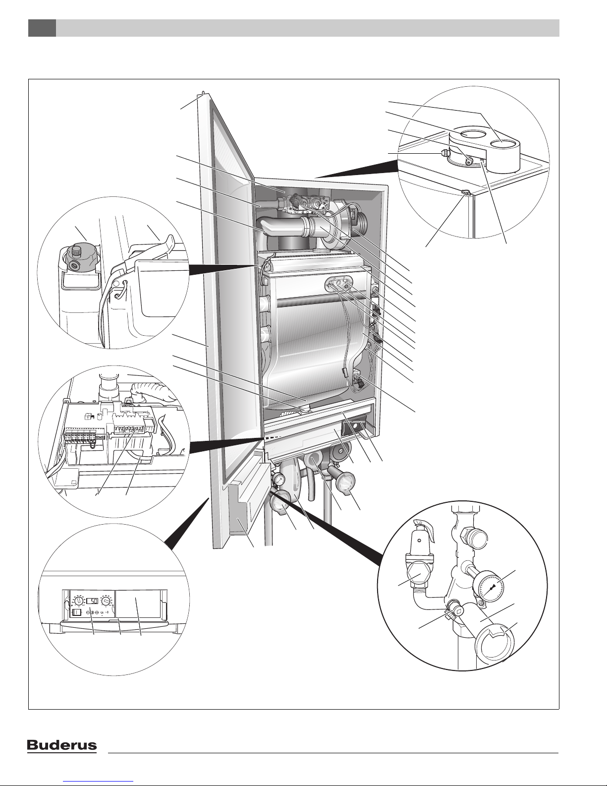
Fig. 1 Logamax plus GB162 with pump group
33
34
35
3738
3639
1
40
44
41
42
43
2
Logamax plus GB162-80 kW/100 kW - Subject to modifications resulting from technical improvements!
Product description
1: BC10 basic controller receptacle
2: Installation option for room controller, e.g. RC35
3: Cover with user manual compartment
4: BC10 basic controller, can be expanded e.g. by the RC35 room controller
5: Connection box (low-voltage and 120 VAC connections)
6: Fan harness and mains lead of the pump
7: Condensate drain outlet
8: Condensate collector
9: Boiler front door
10: Automatic air vent
11: Retaining clips
12: Air intake for the fan
13: Gas pipe
14: Flue gas pipe
15: Door lock
16: Flue gas sensor
17: Flue measuring point
18: Measuring point for air intake
19: Flue gas connection
20: Air intake connection
21: Fan
22: Gas valve
23: Venturi
24: Burner cover
25: Flow temperature sensor
26: Ionization electrode
27: Sighting glass
28: Glow ignitor
29: Safety temperature sensor
30: Heat exchanger
31: Pressure sensor
32: Return temperature sensor
33: Universal Burner Automatic Version 3 (UBA 3)
34: Draw with function module integration options
35: Cover shield
36: Condensate trap
Pump group (scope of delivery):
37: Isolating valve, blue (CH boiler return) with pump, drain cock, check valve and thermometer
38: Manual gas shutoff valve, yellow (GAS)
39: Isolating valve, red (CH boiler flow) with drain cock, pressure gauge and thermometer
40: Pressure gauge
41: Isolating valve
42: Thermometer (optional accessory)
43: Drain valve
44: Safety valve 30 psi (2 bar) (or 50 psi [3.45 bar] = optional)
The pump group also includes an insulation cover (see also pump group installation instructions).
Low loss header (scope of delivery, single appliance only):
45: Low loss header (not illustrated)
3
Logamax plus GB162-80 kW/100 kW - Subject to modifications resulting from technical improvements!
Contents
Contents
1 General information . . . . . . . . . . . . . . . . . . . . . . . .6
2 Safety and general instructions . . . . . . . . . . . . . .7
2.1 Designated use . . . . . . . . . . . . . . . . . . . . . . .7
2.2 Hazard definitions . . . . . . . . . . . . . . . . . . . . .7
2.3 The following instructions must be observed.7
2.4 Heating system water quality . . . . . . . . . . . . .8
2.5 Pump test. . . . . . . . . . . . . . . . . . . . . . . . . . . .8
2.6 Freeze protection . . . . . . . . . . . . . . . . . . . . . .8
2.7 Tools, materials and further equipment . . . . .8
2.8 Disposal . . . . . . . . . . . . . . . . . . . . . . . . . . . . .8
3 Regulations and guidelines . . . . . . . . . . . . . . . . .9
3.1 Massachusetts Installations Only: . . . . . . . . .9
4 Dimensions and connections . . . . . . . . . . . . . . .11
4.1 Without pump group. . . . . . . . . . . . . . . . . . .11
4.2 With pump group . . . . . . . . . . . . . . . . . . . . .12
5 Packaging and transportation . . . . . . . . . . . . . .13
5.1 Scope of delivery . . . . . . . . . . . . . . . . . . . . .13
5.2 Transporting the boiler . . . . . . . . . . . . . . . . .13
9 Start-up procedure . . . . . . . . . . . . . . . . . . . . . . . 45
9.1 Check for gas leaks . . . . . . . . . . . . . . . . . . 46
9.2 Fill the heating system . . . . . . . . . . . . . . . . 47
9.3 Fill the condensate trap with water . . . . . . . 48
9.4 Bleed the gas supply valve. . . . . . . . . . . . . 49
9.5 Check the air/flue gas connection . . . . . . . 49
9.6 Checking the appliance configuration . . . . 50
9.7 Measure the gas inlet pressure
(working pressure) . . . . . . . . . . . . . . . . . . . 50
9.8 Check and adjust the gas/air ratio . . . . . . . 52
9.9 Carry out a leakage test in operating
conditions . . . . . . . . . . . . . . . . . . . . . . . . . . 54
9.10 Measure the flue gases CO emissions. . . . 55
9.11 Carry out a function test . . . . . . . . . . . . . . . 56
9.12 Measure the ionization current . . . . . . . . . . 56
9.13 Test the Ignition Safety shut off device . . . 57
9.14 Boiler settings. . . . . . . . . . . . . . . . . . . . . . . 58
9.15 Final activities. . . . . . . . . . . . . . . . . . . . . . . 60
10 Shutting down the system. . . . . . . . . . . . . . . . . 61
10.1 Shut down the heating system using
the basic controller . . . . . . . . . . . . . . . . . . . 61
10.2 Shutting down the heating system if there
is a risk of freezing (interruption of use) . . . 61
10.3 Shutting down the heating system in
the event of an emergency. . . . . . . . . . . . . 61
6 Installation . . . . . . . . . . . . . . . . . . . . . . . . . . . . . .15
6.1 Requirements for the installation room . . . .15
6.2 Installing the boiler . . . . . . . . . . . . . . . . . . . .15
6.3 Water and Gas connection . . . . . . . . . . . . .17
6.4 Connecting the condensate drain pipe . . . .21
6.5 Combustion Air and Ventilation Openings . .22
6.6 Flue gas adapter . . . . . . . . . . . . . . . . . . . . .24
6.7 Installation of the Exhaust and Air Intake
system . . . . . . . . . . . . . . . . . . . . . . . . . . . . .24
7 Electrical connections . . . . . . . . . . . . . . . . . . . . .30
7.1 External connection board connections . . . .30
7.2 Installing function modules (accessories) . .33
7.3 Electrical wiring diagram . . . . . . . . . . . . . . .37
8 Operation . . . . . . . . . . . . . . . . . . . . . . . . . . . . . . .39
8.1 BC10 basic controller. . . . . . . . . . . . . . . . . .39
8.2 BC10 operating instructions. . . . . . . . . . . . .41
11 Inspection . . . . . . . . . . . . . . . . . . . . . . . . . . . . . . 62
11.1 Prepare the heating system for inspection . 62
11.2 Carry out a visual check for general
signs of corrosion . . . . . . . . . . . . . . . . . . . . 63
11.3 Gas valve leakage test . . . . . . . . . . . . . . . . 63
11.4 Measure the ionization current . . . . . . . . . . 63
11.5 Measure the gas inlet pressure
(working pressure) . . . . . . . . . . . . . . . . . . . 64
11.6 Check and adjust the gas/air ratio . . . . . . . 64
11.7 Carry out a leakage test in operating
conditions . . . . . . . . . . . . . . . . . . . . . . . . . . 64
11.8 Measure the flue gases CO emissions. . . . 64
11.9 Fill the heating system . . . . . . . . . . . . . . . . 64
11.10 Check the air/flue gas connection . . . . . . . 64
12 Maintenance . . . . . . . . . . . . . . . . . . . . . . . . . . . . 65
12.1 Prepare the heating system for
maintenance. . . . . . . . . . . . . . . . . . . . . . . . 65
12.2 Remove the boiler door . . . . . . . . . . . . . . . 65
12.3 Clean the heat exchanger, burner and
condensate trap . . . . . . . . . . . . . . . . . . . . . 66
12.4 Check and adjust the gas/air ratio . . . . . . . 71
12.5 Function check . . . . . . . . . . . . . . . . . . . . . . 71
Logamax plus GB162-80 kW/100 kW - Subject to modifications resulting from technical improvements!4
13 Display information . . . . . . . . . . . . . . . . . . . . . . 72
13.1 Removing the control panel . . . . . . . . . . . . 72
13.2 Replacing the control panel . . . . . . . . . . . . 73
13.3 BC10 Display readings . . . . . . . . . . . . . . . . 73
13.4 BC10 Display settings. . . . . . . . . . . . . . . . . 73
13.5 BC10 Display codes . . . . . . . . . . . . . . . . . . 74
14 Technical specifications . . . . . . . . . . . . . . . . . . 81
14.1 Technical specifications of GB162-boilers
at sea level (0-4,000 ft) . . . . . . . . . . . . . . . . 81
14.2 Technical specifications of GB162-boilers
at high altitude (4,000-10,000 ft). . . . . . . . . 82
15 Reports . . . . . . . . . . . . . . . . . . . . . . . . . . . . . . . . 85
15.1 Start-up report. . . . . . . . . . . . . . . . . . . . . . . 85
15.2 Inspection report . . . . . . . . . . . . . . . . . . . . . 86
15.3 Service report . . . . . . . . . . . . . . . . . . . . . . . 87
Contents
16 Spare parts . . . . . . . . . . . . . . . . . . . . . . . . . . . . . 88
17 Index. . . . . . . . . . . . . . . . . . . . . . . . . . . . . . . . . . . 91
Logamax plus GB162-80 kW/100 kW - Subject to modifications resulting from technical improvements! 5

General information1
1 General information
About these instructions
These Installation Instructions contain important information
for the safe and professional installation, start-up and maintenance of the boiler with boiler input rating of 80 kW and
100 kW.
These Installation Instructions are intended for professional
installers, who have the necessary training and experience
for working on heating and gas systems.
Cascade installation
Special cascade units (accessories) have been developed
to enable this boiler to be installed in a cascade system.
Every cascade unit includes an installation frame, horizontal
headers, connection pipes for the boiler, main gas pipe and
a vertical low loss header.
Cascade units are available for installing the boilers inline or
back-to-back. These cascade units make installing a
cascade system easier and less labor intensive.
Please contact Buderus for further information about
cascade systems.
Updating of documentation
The following technical documentation is available for the
Logamax plus GB162-80 kW/100 kW:
– Installation instructions
– User’s manual
– Service manual.
Please contact us if you have any suggestions for improvement or corrections.
GB162 Natural Gas Propane Gas
80 kW 290,000 btu/hr 270,000 btu/hr
100 kW 333,000 btu/hr 315,000 btu/hr
Table 1 max. input rate
Subject to technical modifications
Slight changes may be made without prior notice to the illustrations, process steps and technical data as a result of our
policy of continuous improvement.
Logamax plus GB162-80 kW/100 kW - Subject to modifications resulting from technical improvements!6
2 Safety and general instructions
Safety and general instructions 2
Please observe these instructions in the interest of your
own safety.
2.1 Designated use
The boiler was designed for heating water for a central
heating system and generating domestic hot water.
The boiler is suitable for connection to fully pumped,
sealed water systems ONLY.
The boiler can be installed either as a single system or as
part of a multiple system (cascade system) with a
maximum of 8 boilers connected together.
2.2 Hazard definitions
The following defined terms are used throughout the documentation to bring attention to the presence of hazards of
various risk levels. Notices give important information
concerning the operation of the product.
DANGER
Indicates the presence of hazards that will
cause severe personal injury, death or
substantial property damage.
WARNING
Indicates the presence of hazards that can
cause severe personal injury, death or
substantial property damage.
CAUTION
Indicates presence of hazards that will or
cause minor personal injury or property
damage.
CAUTION
Risk of electric shock.
Indicates presence of hazards due to electric
shock.
NOTICE
Indicates special instructions on installation,
operation or maintenance that are important
but not related to personal injury or property
damage.
2.3 The following instructions must be
observed
– The boiler must only be used for its designated
purpose, observing the Installation Instructions.
– Only use the boiler in the combinations and with the
accessories and spares listed.
– Maintenance and repairs must only be carried out by
trained professionals.
– You are only permitted to operate the condensing gas
boiler with the combustion air/flue gas system that has
been specifically designed and approved for this type of
boiler.
– Please note that local approval of the flue system and
the condensate connection to the public sewer system
may be required.
– If boiler installation is provided as replacement heater,
DO NOT connect new boiler venting to an existing vent
system, if it is shared with other appliances.
You must also observe:
– The local building regulations stipulating the installation
rules at the time of installation.
– The local building regulations concerning the air intake
and outlet systems and the chimney connection.
– The regulations for the power supply connection.
– The technical rules laid down by the gas utility company
concerning the connection of the gas burner fitting to
the local gas main.
– The instructions and standards concerning the safety
equipment for the water/space heating system.
– The Installation Instructions for building heating
systems.
– The boiler must be located in an area where leakage of
the tank or connections will not result in damage to the
area adjacent to the boiler or to lower floors of the
structure. When such locations cannot be avoided, it is
recommended that a suitable drain pan, adequately
drained, be installed under the boiler. The pan must not
restrict combustion air flow.
– The boiler must be installed such that the gas ignition
system components are protected from water (dripping,
spraying, rain etc.) during boiler operation and service.
– The boiler must not be installed on carpeting.
– Do not restrict or seal any air intake or outlet openings.
– If you find any defects, you must inform the owner of the
system of the defect and the associated hazard in
writing.
Logamax plus GB162-80 kW/100 kW - Subject to modifications resulting from technical improvements! 7
Safety and general instructions2
DANGER
if flammable gas explodes.
Beware if you smell gas: there may be an
explosion hazard!
Warning: If the information in these
instructions is not followed exactly, a fire
or explosion may result causing property
damage, personal injury or death.
z Do not store or use gasoline or other flam-
mable vapors and liquids in the vicinity of
this or any other boiler.
What to do if you smell gas
z Do not try to light any boiler.
z Do not touch any electrical switch; do not
use any phone in your building.
z Immediately call your gas supplier from
a neighbor’s phone. Follow the gas
supplier’s instructions.
z If you cannot reach your gas supplier, call
the fire department.
Installation and service must be performed by
a qualified installer, service agency or the gas
supplier.
WARNING
Danger of fatal accident from explosive
fumes.
z Only carry out work on gas pipes and
fittings if you are properly registered.
– The low loss header and boiler connection set must be
installed (supplied with the boiler).
– When using oxygen-permeable pipes (plastic), e.g. for
floor heating systems, you must separate the system
using secondary heat exchangers.
2.5 Heating system water quality
The quality of the system water is very important. Poor
water quality can damage heating systems due to scale
formation and corrosion. For further details, please see
the accompanying "Water quality requirements for
Logamax plus GB162-80 kW/100 kW" manual.
CAUTION
Risk of system damage due to unsuitable
heating system water.
z If oxygen-permeable pipes are used, e.g.
for underfloor heating systems, the
systems must be separated from one
another by plate heat exchangers.
Unsuitable heating system water
promotes sludge and corrosion formation. This can result in heat exchanger
malfunction and damage.
2.6 Pump test
If the boiler has not been operational for approx. 4 weeks,
the pump will automatically run for 10 seconds every
24 hours. This pump test is first carried out 24 hours after
the main power has been connected to the boiler.
2.7 Freeze protection
WARNING
Dangerous flue gas can escape if the air
supply is insufficient.
z Make sure that air vents are not reduced
in size or obstructed.
z The boiler may only be operated after the
defect has been remedied.
z Warn the user of the system of the defect
verbally and in writing.
2.4 Heating system requirements
– Installing a dirt trap like a y-strainer and a desludging
device is required. This must be installed in the heating
system in the immediate vicinity of the boiler, in an
easily accessible position between the boiler and the
lowest point in the return of the system.
– Clean the dirt trap at every annual service.
– Never use salt bedding type exchangers (ion
exchangers) to soften the water.
The boiler has integrated freeze protection that switches
the boiler ON at a space heating (CH) water temperature
of 45 °F (7 °C) and switches it OFF at a CH flow temperature of 59 °F (15 °C).
This feature does not protect the central heating system
from freezing. If there is a risk of radiators or pipe sections
freezing up, we recommend setting the pump run-over
time to 24 hours. See paragraph 13.4 on page 73.
2.8 Tools, materials and further equipment
For the installation and maintenance of the boiler you will
need the standard tools for space heating, gas and water
fitting. In addition, a handtruck with a fastening belt is
useful.
2.9 Disposal
– Dispose of the boiler packaging in an environmentally
sound manner.
– Dispose of components of the heating system (e. g.
boiler or control device), that must be replaced in an
environmentally responsible manner.
Logamax plus GB162-80 kW/100 kW - Subject to modifications resulting from technical improvements!8
3 Regulations and guidelines
Regulations and guidelines 3
The installation must conform to the requirements of the
authority having jurisdiction or, in the absence of such
requirements, to the latest edition of the National Fuel Gas
Code, ANSI Z223.1./NFPA 54. In Canada, installation
must be in accordance with the requirements of
CAN/CSA B149.1, Natural Gas and Propane Installation
Code.
Where required by the authority having jurisdiction, the
installation must conform to the Standard for Controls and
Safety Devices for Automatically Fired Boilers,
ANSI/ASME CSD-1.
Install CO detectors per local regulations. Boiler requires
yearly maintenance, see chapter 12 "Maintenance",
page 65.
Operating Limits of the boiler:
Max. boiler temperature: 230 °F (110 °C)
Max. operating pressure: 30
– with optional pressure relief valve 50 psi (3.45 bar)
The hot water distribution system must comply with all
applicable codes and regulations. When replacing an
existing boiler, it is important to check the condition of the
entire hot water distribution system to ensure safe operation.
psi (2.6 bar)
3.1 Massachusetts Installations Only:
(a) For all side wall side horizontally vented gas fueled
equipment installed in every dwelling, building or structure
used in whole or in part for residential purposes, including
those owned or operated by the Commonwealth and
where the side wall exhaust vent termination is less than
seven (7) feet above finished grade in the area of the
venting, including but not limited to decks and porches, the
following requirements shall be satisfied:
1. INSTALLATION OF CARBON MONOXIDE
DETECTORS. At the time of installation of the side
wall horizontal vented gas fueled equipment, the
installing plumber or gasfitter shall observe that a hard
wired carbon monoxide detector with an alarm and
battery back-up is installed on the floor level where the
gas equipment is to be installed. In addition, the
installing plumber or gasfitter shall observe that a
battery operated or hard wired carbon monoxide
detector with an alarm is installed on each additional
level of the dwelling, buiding or structure served by the
side wall horizontal vented gas fueled equipment. It
shall be the responsibility of the property owner to
secure the services of qualified licensed professionals
for the installation of hard wired carbon monoxide
detectors.
a. In the event that the side wall horizontally vented
gas fueled equipment is installed in a crawl space
or an attic, the hard wired carbon monoxide
detector with alarm and battery back-up may be
installed on the next adjacent floor level.
b. In the event that the requirements of this
subdivision can not be met at the time of
completion of installation, the owner shall have a
period of thirty (30) days to comply with the above
requirements; provided, however, that during said
thirty (30) day period, a battery operated carbon
monoxide detector with an alarm shall be installed.
2. APPROVED CARBON MONOXIDE DETECTORS.
Each carbon monoxide detector as required in
accordance with the above provisions shall comply
with NPA 720 and be ANSI/UL 2034 listed and
IAS certified.
3. SIGNAGE. A metal or plastic identification plate shall
be permanently mounted to the exterior of the building
at a minimum height of eight (8) feet above grade
directly in line with the exhaust vent terminal for the
horizontally vented gas fueled heating appliance or
equipment. The sign shall read, in print size no less
than one-half (½) inch in size, “GAS VENT DIRECTLY
BELOW. KEEP CLEAR OF ALL OBSTRUCTIONS”.
4. INSPECTION. The state or local gas inspector of the
side wall horizontally vented gas fueled equipment
shall not approve the installation unless, upon
inspections, the inspector observes carbon monoxide
detectors and signage installed in accordance with the
provisions of 248 CRM 5.08(2)(a)1 through 4.
(b) EXEMPTIONS: The following equipment is exempt
from 248 CRM 5.08(2)(a)1 through 4:
1. The equipment listed in Chapter 10 entitled
“Equipment Not Required To Be Vented” in the
most currect edition of NFPA 54 as adopted by the
board: and
2. Product Approved side wall horizontally vented gas
fueled equipment installed in a room or structure
separate from the dwelling, building or structure
used in whole or in part for residential puposes.
Logamax plus GB162-80 kW/100 kW - Subject to modifications resulting from technical improvements! 9

Regulations and guidelines3
(c) MANUFACTURERS REQUIREMENTS - GAS EQUIP-
MENT VENTING SYSTEM REQUIRED.
When the manufacturer of Product Approved side wall
horizontally mounted gas equipment provides a venting
system design or venting system components with the
equipment, the instructions provided by the manufacturer
for the installation of the equipment and venting shall
include:
1. Detailed instructions for the installation of the
venting system or the venting system components:
and
2. A complete parts list for the venting system design
or venting system.
(d) MANUFACTURERS REQUIREMENTS - GAS EQUIPMENT VENTING SYSTEM NOT PROVIDED.
When the manufacturer of Product Approved side wall
horizontally vented gas fueled equipment does not provide
the parts for the venting of flue gases, but identifies
“special venting systems”, the following requirements shall
be satisfied by the manufacturer:
1. The referenced “special venting systems” shall be
included with the appliance or equipment
installation instructions: and
2. The “special venting systems” shall be Product
Approved by the Board, and the instructions for
that system shall include a parts list and detailed
installation instructions.
(e) A copy of all instructions for all Product Approved side
wall horizontally vented gas fueled equipment, all venting
instructions, all parts lists for venting instructions, and/or
venting design instructions shall remain with the appliance
or equipment at the completion of the installation.
Logamax plus GB162-80 kW/100 kW - Subject to modifications resulting from technical improvements!10
4 Dimensions and connections
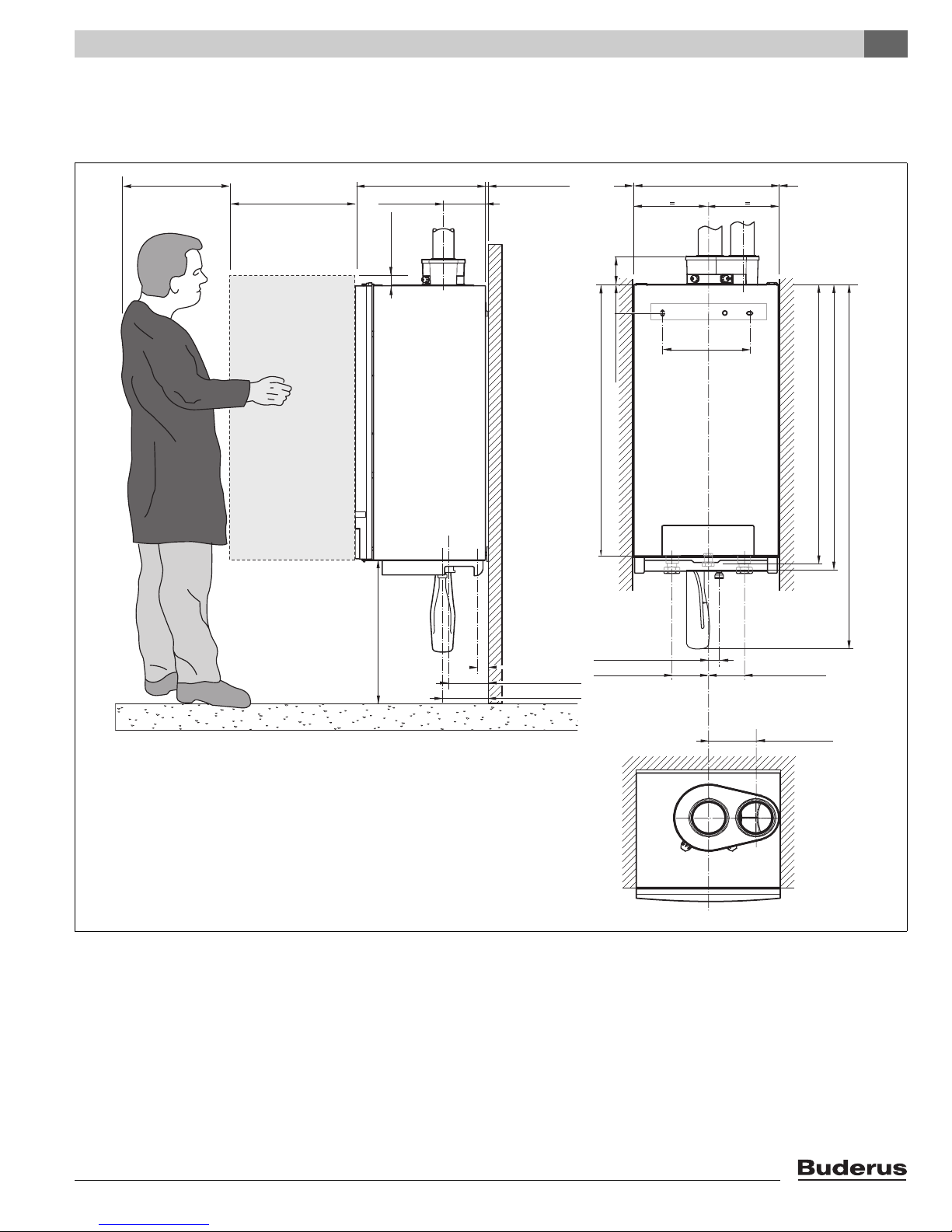
4.1 Without pump group
Dimensions and connections 4
16.5" (420 mm)
20.5" (520 mm)
18.3” (465 mm)
6” (152 mm)
A/B
1.2” (30 mm)
G
D/F
E
0.25” (6 mm)
4.1” (103.5 mm)
0 020.5” (520 mm)
C
16” (406 mm)
5.3” (135 mm)
38.58” (980 mm)
DFE
AB
G
39.5” (1003 mm)
40,55” (1030 mm)
51.6” (1310 mm)
24.8” (630 mm)
1.4” (35 mm)
5.4” (138 mm)
6.4” (162 mm)
The required permanent clearances (closet) are:
in front: 1” (25 mm)
right side: 0
left side: 0
above: 6” (152 mm)
The position selected for installation MUST allow adequate space for servicing in
front of the boiler of at least 16.5” + 20.5” = 37” (940 mm).
Maintain an installation clearance from combustible construction from hot water
piping of at least 1" (25 mm).
Fig. 2 Dimensions and connections without pump group
A (LA) = Flue gas connection;
E (GAS) = Gas connection to boiler;
inside diameter 4” (100 mm)
B (AA) = Air intake connection;
F (RK) = Return;
inside diameter 4” (100 mm)
C (WB) = Wall Bracket (not shown)
G (AKO) = Condensate outlet;
D (VK) = Supply;
G1½’’ union nut with female thread
1.54” (39 mm)
5.1” (130 mm)
5.1” (130 mm)
5.5” (140 mm)
Rp1’’ female thread
G1½’’ union nut with female thread
Ø 32 mm (1¼”) O/D
Logamax plus GB162-80 kW/100 kW - Subject to modifications resulting from technical improvements! 11
Dimensions and connections4
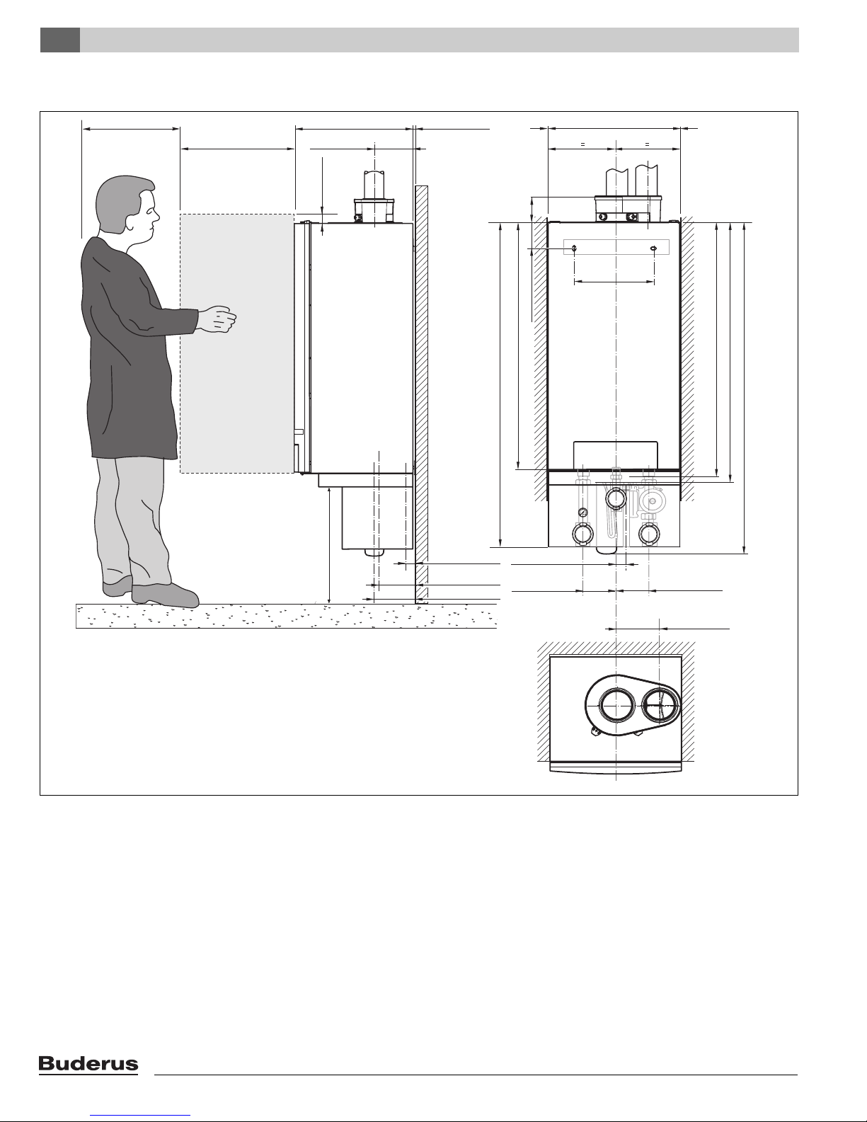
4.2 With pump group
16.5" (420 mm)
20.5" (520 mm)
18.3” (465 mm) 0.25” (6 mm)
6” (152 mm)
A/B
1.2” (30 mm)
4.1” (103.5 mm)
D/F
G
E
0 020.5” (520 mm)
5.3” (135 mm)
38.58” (980 mm)
50.4” (1280 mm)
AB
C
16” (406 mm)
DFE
39.5” (1003 mm)
40,55” (1030 mm)
51.6” (1310 mm)
G
24.8” (630 mm)
H/J
5.4” (138 mm)
6.4” (162 mm)
The required permanent clearances (closet) are:
in front: 1” (25 mm)
right side: 0
left side: 0
above: 6” (152 mm)
The position selected for installation MUST allow adequate space for servicing
in front of the boiler of at least 16.5” + 20.5” = 37” (940 mm).
Maintain an installation clearance from combustible construction from hot water
piping of at least 1" (25 mm).
Fig. 3 Dimensions and connections with pump group
1
The pump group is an accessory.
A (LA) = Flue gas connection;
inside diameter 4” (100 mm)
B (AA) = Air intake connection;
inside diameter 4” (100 mm)
C (WB) = Wall Bracket (not shown)
D (VK) = Supply;
G1½’’ union nut with female thread
E (GAS) = Gas connection to boiler;
Rp1’’ female thread
1.4” (35 mm)
1.54” (39 mm)
5.1” (130 mm)
HI
G
J
5.1” (130 mm)
5.5” (140 mm)
F (RK) = Return;
G1½’’ union nut with female thread
G (AKO) = Condensate outlet;
Ø 32 mm (1¼”) O/D
H (PF) = Pump group supply;
G1½’’ male thread, flat seal
I = Gas connection to pump group;
1” NPT female thread
J (PR) = Pump group return;
G1½’’ male thread, flat seal
Logamax plus GB162-80 kW/100 kW - Subject to modifications resulting from technical improvements!12
5 Packaging and transportation
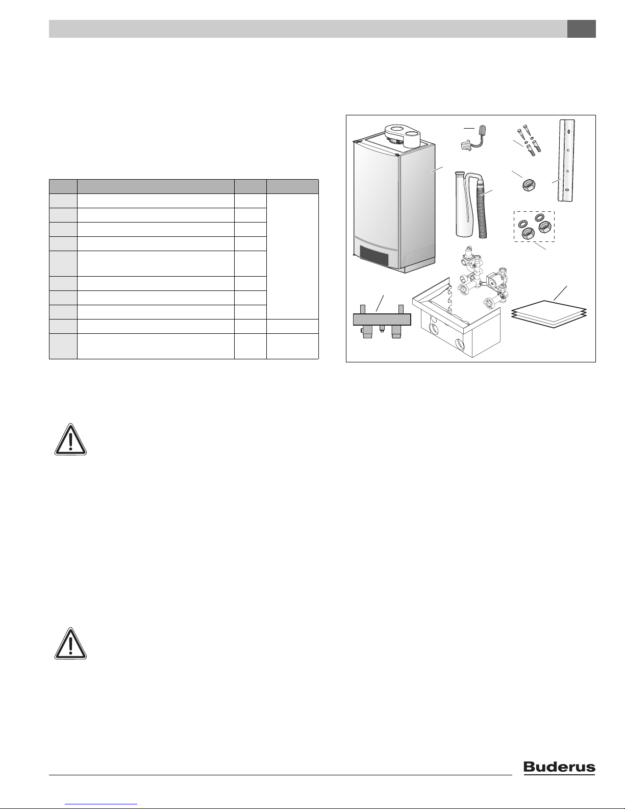
5.1 Scope of delivery
Packaging and transportation 5
The boiler is delivered factory-assembled.
z When receiving the delivery, check if the packaging is
intact.
z Check that all items are included in the delivery (fig. 4).
Pos. Parts Qty Packaging
1 Boiler with casing 1 1 box
2 Wall bracket 1
3 Condensate trap with hose 1
4 Technical documents set 1
5 Supply and return union nuts with
sealing rings
6 Screws and plugs for wall bracket 2
7 Union nut for gas connection 1
8 DHW sensor 1
9 Pump group 1 1 box
10 Low loss header
(single installation only)
Table 2 Items supplied with GB162-80 kW/100 kW
2
1 1 box
5.2 Transporting the boiler
8
1
2
1
3
0
4
10
9
Fig. 4 Items supplied with unit
6
7
3
2
5
4
CAUTION
The boiler may be damaged when it is improperly secured.
z Only transport the boiler using the right
transportation equipment, such as a
handtruck with a fastening belt or special
equipment for manuevering steps.
z During transportation the boiler must be
secured on the transportation equipment to
prevent it from falling off.
z Protect all parts against impacts if they are to
be transported.
z Observe the transportation markings on the
packaging.
CAUTION
The unpacked boiler may be damaged when
not protected against contamination.
z Leave the protective covers on the connec-
tions.
z Cover the flue gas connections at the top of
the boiler with plastic film.
Logamax plus GB162-80 kW/100 kW - Subject to modifications resulting from technical improvements! 13
Packaging and transportation5
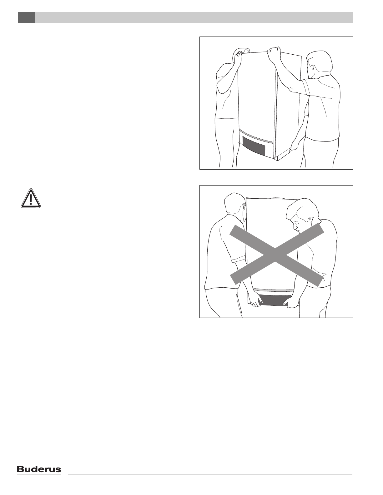
z Always lift and carry the boiler with two people as shown
in fig. 5, or use a handtruck or special equipment.
CAUTION
Damage to the unit by lifting or carrying incorrectly.
z Do not hold the boiler by the door covering
the control panel (fig. 6).
Fig. 5 Lift and carry the boiler correctly
Logamax plus GB162-80 kW/100 kW - Subject to modifications resulting from technical improvements!14
Fig. 6 Incorrect way of lifting and carrying the boiler
6 Installation
6.1 Requirements for the installation room
DANGER
z Install the heating system in a frost-free
room.
z If the boiler is operated dependent on room
air, the installation room must have the
required air vents. DO NOT obstruct these
vents. The air vents must always be free.
z When installed in a room with thin walls or a
thin floor, resonating noise may occur. Install
noise reducing parts if required.
z Do not store any flammable materials or
liquids in the immediate vicinity of the boiler.
z Never use any chlorinated detergents or
halogenated hydrocarbons (e. g. in spray
cans, solvents and detergents, paints,
adhesives).
z Do not allow too much dust to collect on the
boiler.
Installation 6
6.2 Installing the boiler
Observe the installation distances of the combustion air/flue
gas system.
z Before starting installation check that the carrying
capacity of the wall is sufficient for the boiler weight.
NOTICE
z To protect the connection orifice you must
not remove the styrofoam bottom panel.
z Do not lift the boiler by the door covering the
control panel, see paragraph 5.2, page 13.
z Protect the boiler and the combustion
air/flue gas orifice against pollution during
installation.
z Remove the packaging and dispose of it in an environ-
mentally manner.
z Measure the installation height (see chapter 4 "Dimen-
sions and connections", page 11).
Logamax plus GB162-80 kW/100 kW - Subject to modifications resulting from technical improvements! 15
Installation6
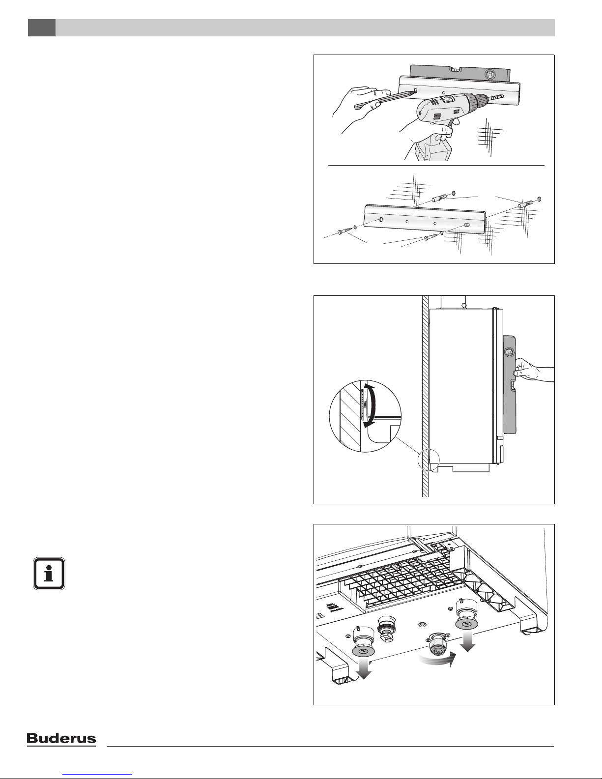
z Mark both holes with the wall bracket (fig. 7) using a spirit
level.
z Install the wall bracket with 2 screws (fig. 7).
z With two people, lift the boiler by holding it by its back and
by the transport rail at its bottom and install it on the wall
bracket (fig. 5, page 14).
z The boiler can be moved sideways to get the correct
position.
z Level the boiler with the set screw and a spirit level
(fig. 8).
A
B
C
D
Fig. 7 Installing the wall bracket
z Remove the protective covers from the bottom of the
boiler (fig. 9).
NOTICE
Some residual water from final testing may
leak away.
Logamax plus GB162-80 kW/100 kW - Subject to modifications resulting from technical improvements!16
Fig. 8 Aligning the boiler with the set screw
Fig. 9 Removing the covers – boiler bottom
Installation 6
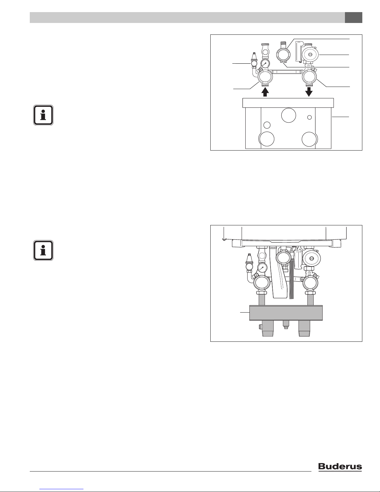
6.3 Water and Gas connection
6.3.1 General
The water and gas connections to the boiler are made using
the pump group, see fig. 10 (scope of delivery). This pump
group includes the circulation pump and a pressure relief
valve.
NOTICE
If you do not use the included pump group, you
have to install a separate circulation pump
under the boiler. This pump must be selected so
that the volume flow through the boiler is sufficient to handle the maximum boiler input rating.
See paragraph 6.3.5 "Installing the pump",
page 19.
z Install the pump group on the boiler in accordance with
the pump group installation instructions.
A single boiler must be installed with the included low loss
header to regulate the flow.
1
2
Fig. 10 Pump group
pos. 1: pressure relief valve
pos. 2: supply water valve
pos. 3: manual gas shutoff valve
pos. 4: circulation pump
pos. 5: gas inlet
pos. 6: return water valve
pos. 7: Pump group cover
3
4
5
6
7
z Install the low loss header (fig. 11, pos. 1).
NOTICE
Avoid installing the boiler above radiation levels.
If the boiler is installed above radiation sections,
a low water cutoff shall be installed and wired to
the boiler. Follow local code or in case of use of
a low water cutoff, be aware to use an air vent,
in order to prevent the boiler from shutting down
unnecessarily.
6.3.2 Connecting the pressure relief valve (PRV)
The pressure relief valve is a part of the supplied pump
group, see fig. 10. A listed ASME pressure relief valve
supplied with the boiler must be installed at the time of installation. No valve is to be placed between the PRV and the
boiler.
No reducing coupling or other restriction may be installed in
the discharge line. The discharge line must be a minimum of
4” (100 mm) above a drain and installed such that it allows
complete drainage of both the PRV and the line. The location of the PRV must be readily accessible for servicing or
replacement and be mounted as close to the boiler as
possible. To install the PRV, a suitable fitting connected to
an extension on a “T” fitting can be sweated to the hot water
line. Support all piping.
Maintain an installation clearance from combustible
construction of at least 1” (25 mm) from the hot water piping.
1
Fig. 11 Low loss header
Logamax plus GB162-80 kW/100 kW - Subject to modifications resulting from technical improvements! 17
Installation6
6.3.3 Making the gas connection
DANGER
Only carry out work on gas lines if you are a
qualified gas fitter.
z The manual gas shutoff valve is part of the pump group,
and is installed in accordance with the pump group installation instructions.
z Determine proper size gas pipe for the installation using
table 3 and table 4. Do not forget the pipe fitting losses
and observe proper size of the fittings.
z Connect the gas supply pipe to the manual gas shutoff
valve, so that it is free from any strain.
NOTICE
When installing the gas supply connection, it
must comply with local regulations or, if such
regulations do not exist, with the National Fuel
Gas Code, ANSI Z 223.1./NFPA 54.
In Canada, the gas supply connection must
comply with local regulations or, if such regulations do not exist, with CAN/CSA B149.1,
Natural Gas and Propane Installation Code.
A sediment trap must be provided upstream of the manual
gas shutoff valve, but downstream of the appliance gas
valve.
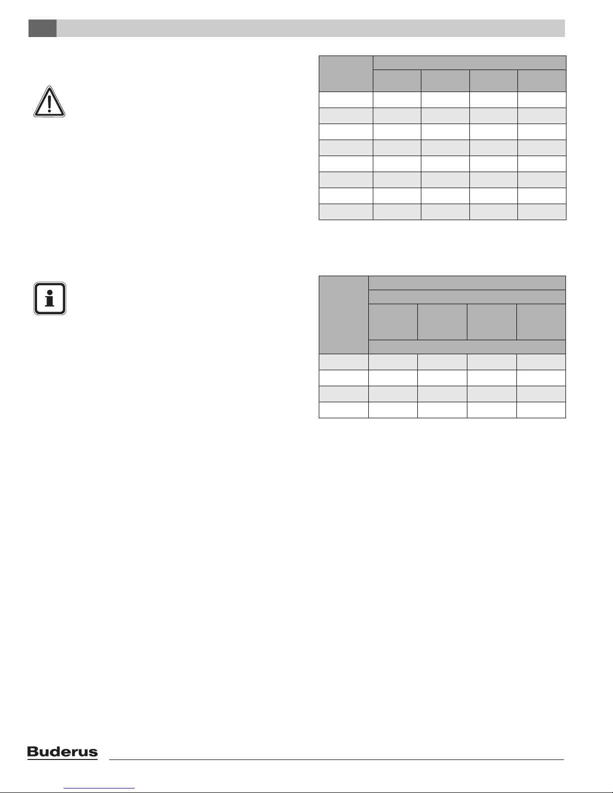
Length of
pipe in feet
(m)
10 (3.05) 278 520 1,060 1,600
20 (6.1) 190 350 730 1,100
30 (9.15) 152 285 590 890
40 (12.2) 130 245 500 760
50 (15.25) 115 215 440 670
75 (22.88) 93 175 360 545
100 (30.5) 79 160 305 480
150 (47.25) 64 120 250 380
Table 3 Gas Pipe Capacity for different pipe sizes
1 Maximum pipe capacity in ft3/hr, based on a specific gravity of
.60 (42 mbar) and a inlet gas pressure of 14 inches W.C.
(35 mbar) or less and a pressure drop of .3 inches W.C. (20 mbar)
Steel pipe
diameter
in inches
(mm)
¾ (19) 2.1 (0.64) 4.1 (1.25) 0.5 (0.15) 1.25 (0.38)
1 (25) 2.6 (0.79) 5.2 (1.59) 0.6 (0.18) 1.60 (0.49)
1 ¼ (32) 3.5 (1.07) 6.9 (2.11) 0.8 (0.24) 2.15 (0.66)
1 ½ (38) 4.0 (1.22) 8.0 (2.44) 0.9 (0.27) 2.50 (0.76)
Table 4 Equivalent length for pipe fittings in feet
Gas Volume Capacity in ft3 / hr
¾" 1" 1 ¼" 1 ½"
Equivalent length for Pipe Fittings in feet (m)
Type of pipe fitting
90°-Elbow Tee
(flow thru
branch)
Equivalent length in feet (m)
Gate valve Gas cocks
1
Logamax plus GB162-80 kW/100 kW - Subject to modifications resulting from technical improvements!18
6.3.4 Installing the heating supply and return pipe
NOTICE
When using plastic pipes, observe the supplier’s
instructions - especially those referring to
recommended jointing techniques and the
notes relating to the heating system water on
page 8.
NOTICE
To prevent contamination in the heating system
we recommend you integrate a dirt filter (fig. 12,
pos. 10) in the return pipe, near the boiler. In an
old system it is a requirement to install a dirt
filter. Also install shutoff valves to enable filter
cleaning immediately upstream and downstream of the dirt filter (scale cartridge or
y-strainer).
z Connect the supply pipe with a flat rubber seal installed
to the Supply connection (fig. 12, pos. 1) making sure it
is not under stress. Use a supply pipe with a minimum
diameter of 1½" (38 mm).
z Connect the return pipe with a flat rubber seal installed to
the Return connection (fig. 12, pos. 2) making sure it is
not under stress. Use a return pipe with a minimum
diameter of 1½" (38 mm).
Installation 6
1
6
35
Fig. 12 Connecting the boiler supply and return
pos. 1: Supply
pos. 2: Return
pos. 3: Isolating valves
pos. 4: Drain cock
pos. 5: Gas valve
pos. 6: Pressure relief valve
pos. 7: Condensate trap
pos. 8: Pump
pos. 9: Non-return valve
pos. 10: Dirt filter (for example scale cartridge or y-strainer)
2
48
9
>1” (2.54 cm)
3
7
10
3
3
6.3.5 Installing the pump
Always use the supplied Buderus pump group and the low
loss header when installing a single boiler so correct flows
are guaranteed. It is not necessary to install a low loss
header for cascade systems.
z Install the pump (fig. 12, pos. 8) in the return circuit
(fig. 12, pos. 2).
Logamax plus GB162-80 kW/100 kW - Subject to modifications resulting from technical improvements! 19
Installation6
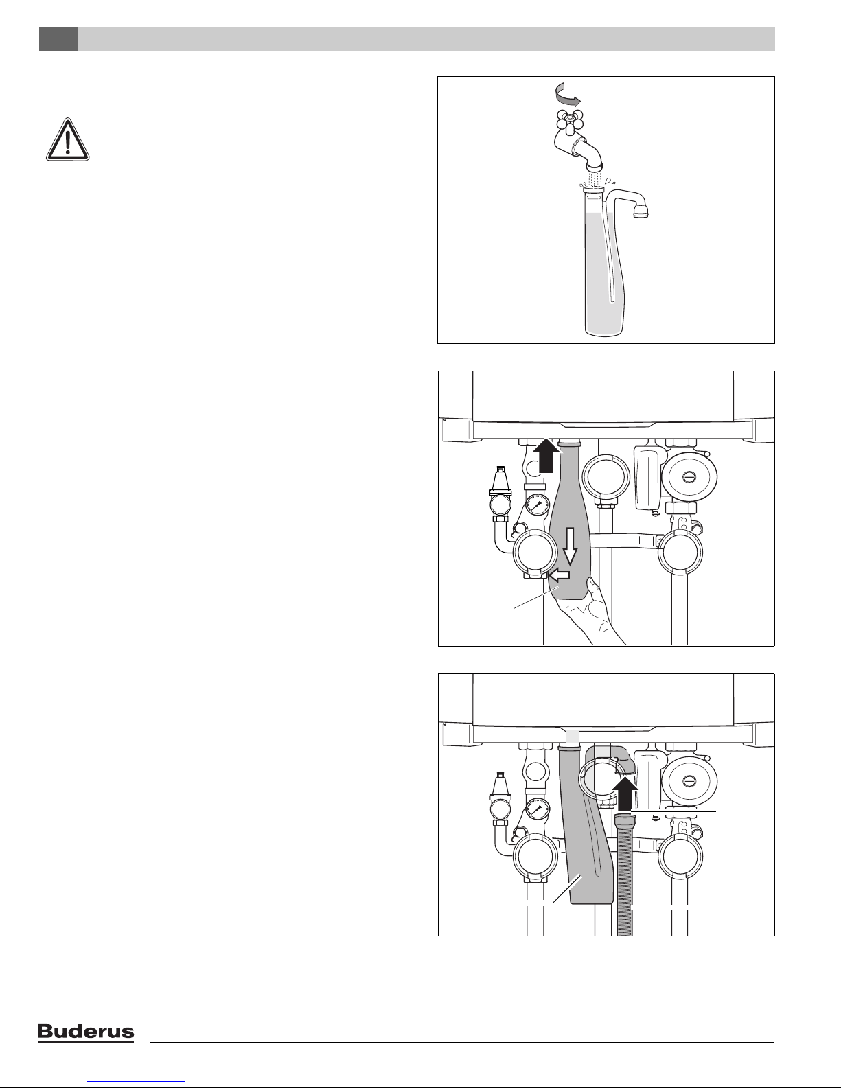
6.3.6 Installing the condensate trap
WARNING
Danger of fatal accident due to poisoning.
z If the condensate trap is not filled with water,
flue gas can escape and put people's lives at
risk.
High temperature applications:
z Fill the condensate trap (supplied with the boiler) with
water (fig. 13). Use mineral oil in case of high temperature systems and non-condensing applications.
z Connect the condensate trap (fig. 14, pos. 1) to the
condensate outlet. The condensate trap has a bayonet
connector, insert and turn ¼ rotation clockwise to click
into position.
Fig. 13 Filling the condensate trap with water
z Connect the condensate trap hose (fig. 15, pos. 3) and
the rubber sleeve (fig. 15, pos. 2) to the condensate trap
(fig. 15, pos. 1).
1
Fig. 14 Installing the condensate trap
1
Fig. 15 Installing the condensate trap hose
2
3
Logamax plus GB162-80 kW/100 kW - Subject to modifications resulting from technical improvements!20
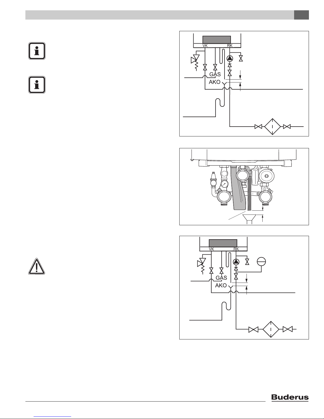
6.4 Connecting the condensate drain pipe
NOTICE
The condensate must be drained from the boiler
in accordance with local, state or federal rules
and regulations.
NOTICE
Use materials approved by the authority having
jurisdiction. In the absence of such authority,
PVC and CPVC pipe must comply with ASTM
D1785, F441 or D2665. Cement and primer
must comply with ASTM D2564 or F493.
For Canada, use ULC certified PVC or CPVC
pipe, fittings and cement.
z Install the condensate drain pipe taking the following into
account:
– An air gap of at least 1” (2.54 cm) must be maintained
between the boiler condensate trap hose and the
condensate pipework, see fig. 16 and fig. 17.
– If the condensate outlet of the boiler is lower than the
drain, a condensate pump must be used.
– The condensate produced by the boiler has a pH value
between 3 and 4.
z Install a neutralization unit if required by the local code.
Installation 6
>1” (2.54 cm)
1
Fig. 16 Connecting the condensate trap
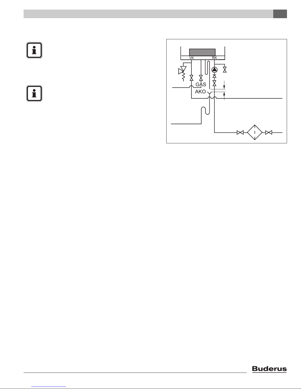
6.4.1 Connecting the expansion vessel in a singleboiler system
CAUTION
Damage to the installation due to faulty pressure
relief valve.
z The expansion vessel must be of sufficient
capacity.
z Connect the expansion tank to the boiler return. If a
check valve is available: connect the expansion vessel to
the CH-side of the check valve in the return circuit
(fig. 18, pos. 1).
1
Fig. 17 Condensate drainage pipe
> 1” (2.54 cm)
1
>1” (2.54 cm)
Fig. 18 Connecting the expansion vessel in a single-boiler
system
Logamax plus GB162-80 kW/100 kW - Subject to modifications resulting from technical improvements! 21
Installation6
6.5 Combustion Air and Ventilation
Openings
Provisions for combustion and ventilation air must be made
in accordance with section 5.3, Air for Combustion and
Ventilation, of the National Flue Gas Code,
ANSI Z223.1/NFPA 54, or Sections 7.2, 7.3 or 7.4 of
CAN/CGA B149, Installation Codes, or applicable provisions of the local building codes.
CAUTION
BOILER DAMAGE AND OPERATIONAL
FAILURES !
Due to insufficient or improper openings for
combustion air and/or ventilation of the boiler
room.
Provisions for combustion air and ventilation are
always required, regardless whether the
combustion air is taken from the outside (sealed
combustion) or inside (room air for combustion).
Insufficient ventilation of the boiler room can
lead to high air temperatures. This can result in
boiler damage.
– Make sure that intake and exhaust openings
are sufficiently sized and no reduction or
closure of openings takes place.
– When the problem is not resolved, do not
operate the boiler.
– Please note these restrictions and its
dangers to the operator of the boiler.
WARNING
BOILER DAMAGE !
Due to contaminated air.
– Boiler must be clear and free from
combustible materials, gasoline and other
flammable vapors and liquids, and corrosive
liquids and vapors.
Never use chlorine and hydrocarbon
containing chemicals (such as spray
chemicals, solution and cleaning agents,
paints, glues etc) in the vicinity of the boiler.
– Do not store and use these chemicals in the
boiler room.
– Avoid excessive dust formation and build-up.
NOTICE
When one expects contaminated combustion
air (near swimming pools, chemical cleaning
operations and hair salons), sealed combustion
operation is recommended.
Logamax plus GB162-80 kW/100 kW - Subject to modifications resulting from technical improvements!22
DANGER
Fire danger due to flammable materials or
liquids.
– Do not store flammable materials and
liquids in the immediate vicinity of the
boiler.
All Air from Inside the Building (room air)
The closet shall be provided with two permanent openings
communicating directly with an additional room(s). The total
input of all gas utilization equipment installed in the
combined space shall be considered in making this determination. Each opening shall have a minimum free area of
1 square inch per 1,000 Btu per hour of total input rating of
all gas utilization equipment in the confined space, but no
less than 100 square inches. One opening shall commence
within 12 inches (305 mm) of the top, and one opening shall
commence within 12 inches (305 mm) of the bottom of the
enclosure. The minimum dimension of air openings shall be
not less than 4 inches (101.6 mm).
Installation 6
All Air from Outdoor (sealed combustion)
The closet shall be provided with two permanent openings,
one commencing within 12 inches (305 mm) from the top,
and one commencing within 12 inches (305 mm) from the
bottom of the enclosure. The openings shall communicate
directly, or by ducts, with the outdoors or spaces (crawl or
attic) that freely communicate with the outdoors.
The minimum dimension of air openings shall be no less
than 4 inches (101.6 mm).
1. Where directly communicating with the outdoors, each
opening shall have a minimum free area of 1 square
inch per 4,000 Btu/hr of total input rating of all
equipment in the enclosure.
2. Where communicating with the outdoors through
vertical ducts, each opening shall have a minimum free
area of 1 square inch per 4,000 Btu/hr of total input
rating of all equipment in the enclosure.
3. Where communicating with the outdoors through
horizontal ducts, each opening shall have a minimum
free area of 1 square inch per 2,000 Btu/hr of total input
rating of all equipment in the enclosure.
4. Where ducts are used, they shall be of the same crosssectional area as the free area of the opening to which
they connect.
Logamax plus GB162-80 kW/100 kW - Subject to modifications resulting from technical improvements! 23
Installation6
6.6 Flue gas adapter
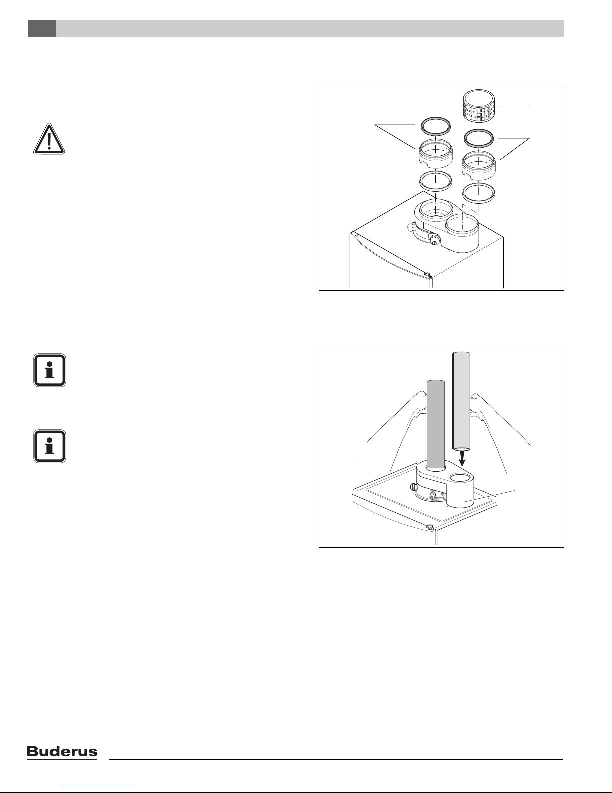
z When installing PVC vent pipes remove the upper lip ring
and insert (fig. 19, pos. 1).
CAUTION
DO NOT use lubricants to avoid degradation of
the lip rings.
z In case of open venting, use basket (fig. 19, pos. 2) on
the air intake.
6.7 Installation of the Exhaust and Air Intake
system
2
1
1
Fig. 19 Connecting the flue gas adapter (parallel)
NOTICE
Consult local and state codes pertaining to
special building code and fire department
requirements. Adhere to national code requirements.
NOTICE
Observe the listed maximum lengths of vent
system, which are boiler model dependent.
The maximum permissible lengths are listed in
table 5, page 28.
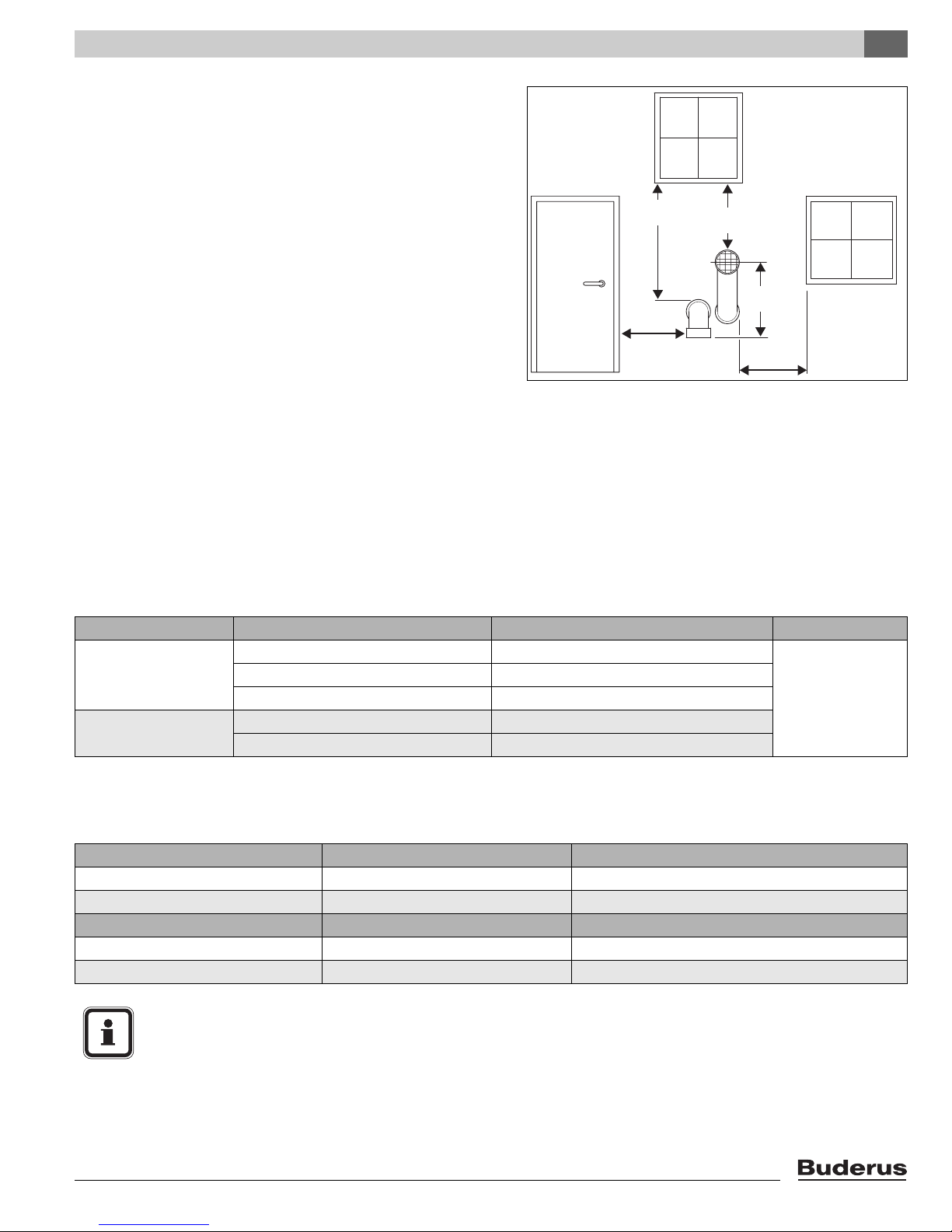
Optional vent kits are:
– horizontal, two-pipe, parallel wall terminal fields.
The termination shall be at least 4 ft (1,220 mm) for the U.S.
and 6 ft (1,830 mm) for Canada away from a gas utility
meter, service regulator or the like (for room air applications
only).
The termination shall terminate at least 4 ft (1,220 mm)
below, 4 ft (1,220 mm) horizontally from, or 1 ft (305 mm)
above any door, window, or gravity air inlet into any building.
2
1
Fig. 20 Vent pipes
Logamax plus GB162-80 kW/100 kW - Subject to modifications resulting from technical improvements!24
Vent must be at least 12 inches (305 mm) above grade,
anticipated snow line or roof surface (Canada 18” (457 mm)
minimum) (see fig. 21).
Vent termination must be at least 7 ft (2,135 mm) above
a public walkway (see fig. 22).
Vent must be 3 ft (915 mm) above any forced air intake
within 10 ft (3,050 mm) (see fig. 22).
Do not extend exposed vent pipe outside the building
beyond recommended distance. Condensate could freeze
and block vent pipe.
Vent should terminate at least 3 ft (915 mm) away from adjacent walls, inside corners and 5 ft (1525 mm) below roof
overhang (see fig. 22).
It is not recommended to terminate vent above any door or
window, condensate can freeze causing ice formations.
Do not use chimney as a raceway if another boiler or fireplace is vented into or through chimney.
All non-steel vent pipes must be glued, except for the flue
gas adapter. Installed you can slide the pipe onto the
adapter, properly supported and the exhaust pipe must be
pitched a minimum of a ¼ inch (6.35 mm) per foot back to
the boiler. This allows the condensate to drain away.
All non-steel combustion air and vent pipe materials and
fittings must comply with the following and must be UL
approved venting material:
Installation 6
12" (305 mm)
minimum
12" (305 mm)
minimum
Fig. 21 Vent and air pipe position (1) of a sealed combustion
system
12" (305 mm)
minimum
EXHAUST
INTAKE
12" (305 mm)
minimum
12" (305 mm)
minimum
Item Material United states Canada
4” (100 mm) Vent or air
pipe and fitting
Pipe
cement/ primer
* Components of the certified vent systems must not be interchanged with other vent systems or unlisted pipe fittings Plastic components, and specified
primers and glues of the certified vent system must be from a single system manufacturer and not intermixed with other system manufacturer's vent
system parts.
PVC schedule 40, 80 ANSI/ASTM D1785
PVC-DWV ANSI/ASTM D2665
CPVC schedule 40, 80 ANSI/ASTM F441
PVC ANSI/ASTM D2564
CPVC ANSI/ASTM F493
BH Gas venting
systems,
ULC S636 *
Approved flue material are from:
Roof terminals Flue System (trade name) Supplier
4”/6" (100/150 mm) concentric PVC IPEX
4” (100 mm) parallel stainless steel Flex-L
Wall terminals Flue System (trade name) Supplier
4” (100 mm) parallel stainless steel Flex-L
90°-elbow with inlet screen PVC/stainless steel Z-Flex/Heat Fab
NOTICE
- DO NOT use cellular core pipe.
- DO NOT use PVC when using anti-freeze in the primary circuit of the boiler. Use CPVC or stainless steel only!
Logamax plus GB162-80 kW/100 kW - Subject to modifications resulting from technical improvements! 25
Installation6
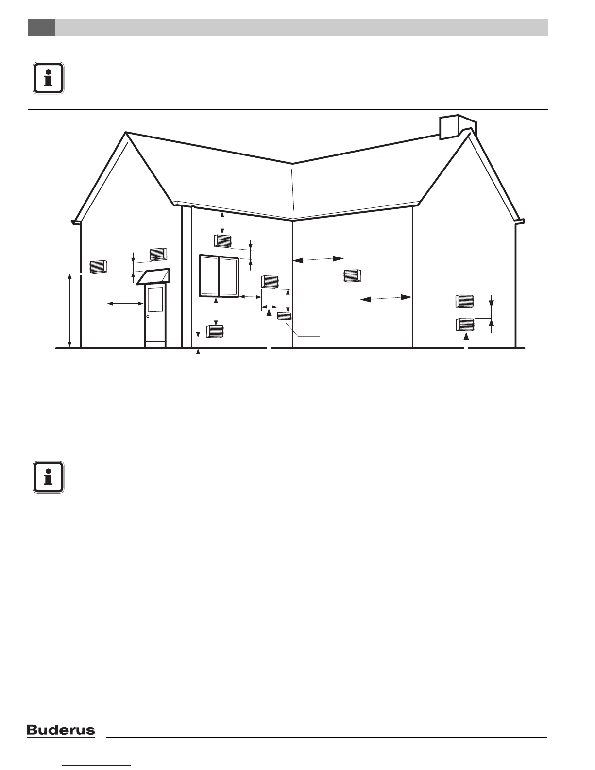
NOTICE
A minimum clearance of 4 ft (1,220 mm) horizontally from and in no case above and below, unless a 4-foot
(1,220 mm) horizontal distance is maintained, from electric meters, gas meters, regulators and relief equipment
(1525 mm)
5'
1'
1'
(305 mm)
4'
7'
(2135 mm)
Fig. 22 Vent and air pipe position (2) of a system with combustion air supply from the room (non-room sealed)
(1220 mm)
at least 1 ft (305 mm)
above grade and snow line
4'
(1220 mm)
(1220 mm)
(305 mm)
4'
3'
Exhaust terminal must be at least 3 ft (915 mm)
above forced air inlet within 10 ft (3,050 mm)
3'
(915 mm)
(1220 mm)
3'
(915 mm)
Forced
Air Inlet
Gravity Air Inlet
Below are approved examples of vertical and horizontal
venting installation
NOTICE
z Place pipe supports every 5 feet (1,525 mm)
of horizontal and vertical run, beginning with
support near boiler.
z The condensate must be drained in accor-
dance with the applicable rules.
See paragraph 6.4: "Connecting the
condensate drain pipe" on page 21.
z Periodic cleaning of the vent terminal and
air-intake screens is mandatory.
z Avoid locating vent terminals near equip-
ment or construction which can be subject to
degradation from exhaust gases.
1'
(305 mm)
Logamax plus GB162-80 kW/100 kW - Subject to modifications resulting from technical improvements!26
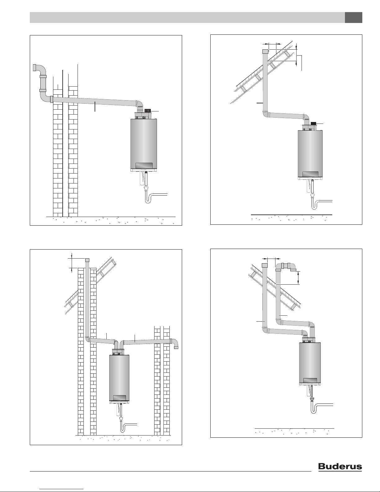
EXHAUST
INTAKE
EXHAUST
10"- 0" MIN
(250 mm - 0 mm MIN)
Installation 6
12” (300 mm) over maximum
snow level or 24” (600 mm)
whichever is greater
INTAKE
Fig. 24 Horizontal venting system (room air only) -
Situation 1
12” (300 mm) over maximum
snow level or 24” (600 mm)
whichever is greater
Exhaust
Intake
Fig. 23 Vertical venting system (room air only)
10"- 0" MIN
(250 mm - 0 mm MIN)
12" (300 mm) OVER
MAXIMUM SNOW LEVEL
OR 24" (600 mm)
WHICHEVER IS
GREATER
EXHAUST
INTAKE
4" (102 mm)
4" (102 mm)
Fig. 26 Vertical venting system (sealed combustion)
Logamax plus GB162-80 kW/100 kW - Subject to modifications resulting from technical improvements! 27
Fig. 25 Vertical parallel venting system (sealed
combustion) - Situation 1
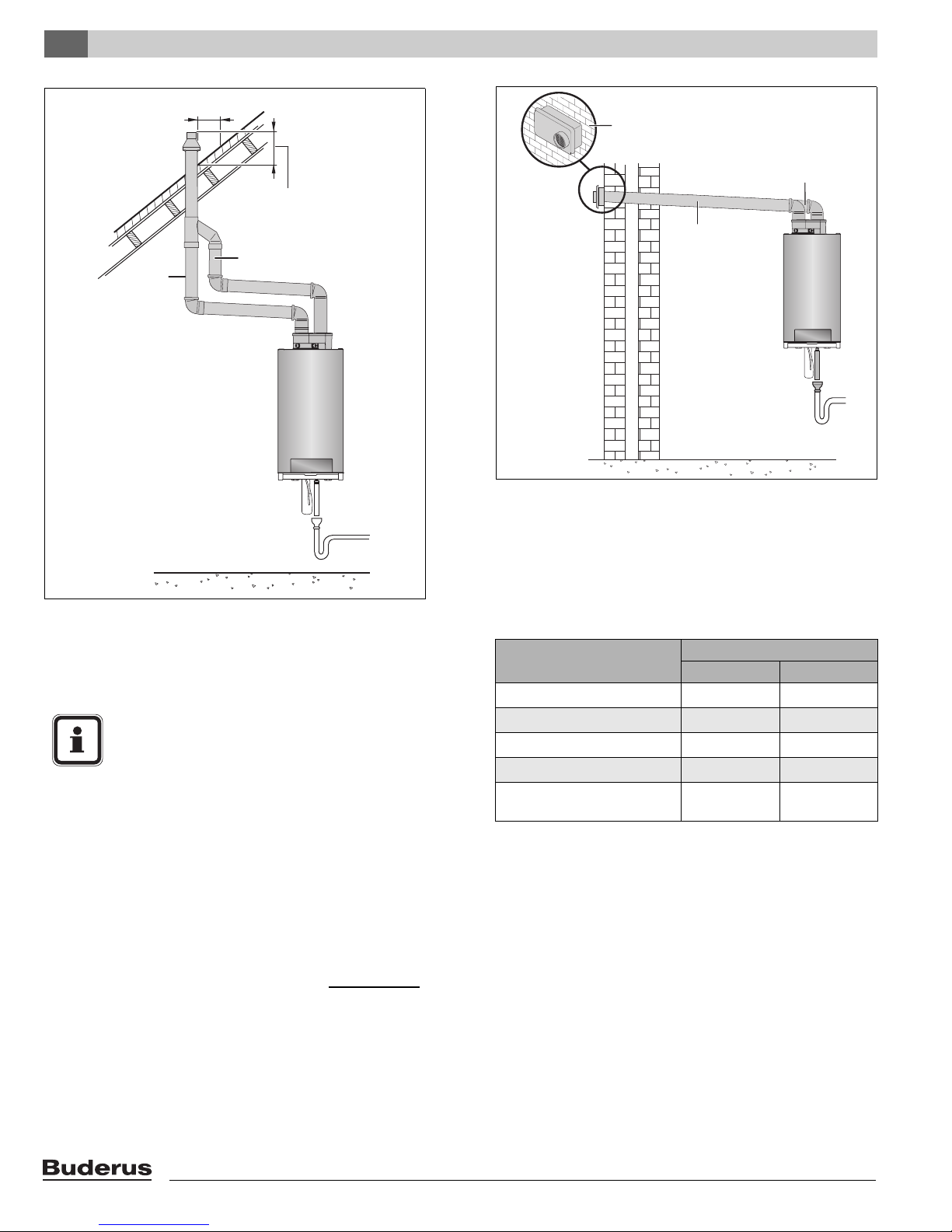
Installation6
10”-0“ MIN
(250 mm - 0 mm MIN)
WALL TERMINATION
INTAKE (BEHIND)
Exhaust
12” (300 mm) over maximum
snow level or 24” (600 mm)
whichever is greater
Intake
EXHAUST
Fig. 27 Horizontal venting system (sealed combustion) -
Situation 2 (PVC only)
4" (102 mm)
Fig. 28 Vertical venting system (sealed combustion)
Do not exceed the total equivalent venting length of 100 feet
(30,480 mm) maximum requirement each for the intake and
exhaust piping.
NOTICE
Appliance input rates are based on minimum
vent length operation. Longer vent lengths
(up to maximum) will reduce the input proportionally.
See table 5 for the Friction Loss Equivalent in piping and
fittings.
Example:
When you end up using 3 x 45°-elbows and the concentric
roof terminal, then the total venting length may not exceed
68 feet (20.72 m).
3 x 45°-elbow = 3 x 4 ft (1.22 m) = 12 ft (3.66 m)
concentric roof terminal 4"/6" = 20 ft (6.10 m)
Total friction loss equivalent = 32 ft (9.76 m)
Total venting length for this example is:
GB162-80 kW/100 kW = 100 ft (30.48 m) - 32 ft (9.76 m) =
68 ft (20.72 m) each for the intake and exhaust piping.
Fittings or Piping Equivalent
feet m
45 degree elbow
90 degree elbow
plastic pipe per foot
parallel vent kit
concentric roof terminal
41.22
7 2.13
10.30
2 0.61
20 6.10
4"/6" (100/150 mm)
Table 5 Friction Loss Equivalent in piping and fittings
Logamax plus GB162-80 kW/100 kW - Subject to modifications resulting from technical improvements!28
 Loading...