

Buderus Logamatic TC100 Installation And Operating Instructions Manual
Installation and operating instructions
Remotely operated controller
Logamatic TC100
6720889234 (2018/10) en
Table of contents
Table of contents 1 Safety instructions
1 Safety instructions. . . . . . . . . . . . . . . . . . . . . . . . . . . . . . . . . . . . 2
1.1 Explanation of symbols . . . . . . . . . . . . . . . . . . . . . . . . . . 2
1.2 Safety instructions . . . . . . . . . . . . . . . . . . . . . . . . . . . . . . 2
2 Environmental protection/disposal . . . . . . . . . . . . . . . . . . . . . 2
3 Product information . . . . . . . . . . . . . . . . . . . . . . . . . . . . . . . . . . 3
3.1 Scope of delivery . . . . . . . . . . . . . . . . . . . . . . . . . . . . . . . 3
3.2 Accessories . . . . . . . . . . . . . . . . . . . . . . . . . . . . . . . . . . . 3
3.3 Warranty conditions. . . . . . . . . . . . . . . . . . . . . . . . . . . . . 3
3.4 Declaration of Conformity (Europe) . . . . . . . . . . . . . . . . 3
3.5 Data privacy . . . . . . . . . . . . . . . . . . . . . . . . . . . . . . . . . . . 3
3.6 Data connection . . . . . . . . . . . . . . . . . . . . . . . . . . . . . . . . 3
3.7 Proximity sensor and touch screen. . . . . . . . . . . . . . . . . 3
3.8 Ambient Light . . . . . . . . . . . . . . . . . . . . . . . . . . . . . . . . . . 3
4 Assembly . . . . . . . . . . . . . . . . . . . . . . . . . . . . . . . . . . . . . . . . . . . . 3
4.1 Prior to installation. . . . . . . . . . . . . . . . . . . . . . . . . . . . . . 3
4.2 Determining the installation location . . . . . . . . . . . . . . . 3
4.3 Fitting the wall plate. . . . . . . . . . . . . . . . . . . . . . . . . . . . . 4
4.4 Connecting to the heat source. . . . . . . . . . . . . . . . . . . . . 4
4.5 Installing (deinstalling) the controller . . . . . . . . . . . . . . . 5
5 Commissioning . . . . . . . . . . . . . . . . . . . . . . . . . . . . . . . . . . . . . . . 5
5.1 Powering up Logamatic TC100. . . . . . . . . . . . . . . . . . . . 5
5.2 Software update. . . . . . . . . . . . . . . . . . . . . . . . . . . . . . . . 5
5.3 Operation of the touch screen. . . . . . . . . . . . . . . . . . . . . 5
5.4 Connecting with WLAN network . . . . . . . . . . . . . . . . . . . 5
5.5 Entering the WLAN network password . . . . . . . . . . . . . . 6
5.6 MyMode app. . . . . . . . . . . . . . . . . . . . . . . . . . . . . . . . . . . 6
5.7 Electronic thermostatically controlled radiator
valve . . . . . . . . . . . . . . . . . . . . . . . . . . . . . . . . . . . . . . . . . 6
1.1 Explanation of symbols
Information symbol
Important information is placed between 2 lines and marked with an
i-symbol in a square.
Additional symbols
Symbol Meaning
▶ a step in an action sequence
a reference to a related part in the document
• a list entry
– a list entry (second level)
Tab le 1
Please read this instruction carefully before use.
1.2 Safety instructions
This temperature controller is used to control a heat source in your
dwelling.
• Do not disassemble the temperature controller under any
circumstances.
• Avoid high temperatures, moisture and dusty environments.
• In order to prevent a short circuit or damage to the controller: Do not
use any liquids or cleaning agents when cleaning.
• Switch off the mains voltage of the heat source before installing.
6 Operating the appliance . . . . . . . . . . . . . . . . . . . . . . . . . . . . . . . 6
6.1 Start screen . . . . . . . . . . . . . . . . . . . . . . . . . . . . . . . . . . . 6
6.2 Symbol background . . . . . . . . . . . . . . . . . . . . . . . . . . . . . 7
6.3 Tab pages . . . . . . . . . . . . . . . . . . . . . . . . . . . . . . . . . . . . . 7
6.4 Temperature setting. . . . . . . . . . . . . . . . . . . . . . . . . . . . . 7
6.5 Manual operation or time program . . . . . . . . . . . . . . . . . 7
6.6 Away setting . . . . . . . . . . . . . . . . . . . . . . . . . . . . . . . . . . . 7
6.7 DHW heating. . . . . . . . . . . . . . . . . . . . . . . . . . . . . . . . . . . 8
6.8 Settings. . . . . . . . . . . . . . . . . . . . . . . . . . . . . . . . . . . . . . . 8
6.8.1 WLAN setting . . . . . . . . . . . . . . . . . . . . . . . . . . . . . . . . . . 8
6.8.2 Reset. . . . . . . . . . . . . . . . . . . . . . . . . . . . . . . . . . . . . . . . . 8
6.8.3 Firmware versions . . . . . . . . . . . . . . . . . . . . . . . . . . . . . . 8
7 Faults . . . . . . . . . . . . . . . . . . . . . . . . . . . . . . . . . . . . . . . . . . . . . . . 8
8 Technical data. . . . . . . . . . . . . . . . . . . . . . . . . . . . . . . . . . . . . . . . 9
9 ErP Class . . . . . . . . . . . . . . . . . . . . . . . . . . . . . . . . . . . . . . . . . . . . 9
10 List of used Open Source Components . . . . . . . . . . . . . . . . . . . 9
11 Appendix . . . . . . . . . . . . . . . . . . . . . . . . . . . . . . . . . . . . . . . . . . . 10
11.1 Apache License 2.0 . . . . . . . . . . . . . . . . . . . . . . . . . . . . 10
11.2 BSD (Three Clause License) . . . . . . . . . . . . . . . . . . . . . 11
11.3 MIT License. . . . . . . . . . . . . . . . . . . . . . . . . . . . . . . . . . . 11
11.4 Texas Instruments-Software License Agreement. . . . . 11
2 Environmental protection/disposal
Environmental protection is a fundamental corporate strategy of the
Bosch Group.
The quality of our products, their economy and environmental safety are
all of equal importance to us and all environmental protection legislation
and regulations are strictly observed.
We use the best possible technology and materials for protecting the
environment taking account of economic considerations.
Packaging
Where packaging is concerned, we participate in country-specific
recycling processes that ensure optimum recycling.
All of our packaging materials are environmentally compatible and can be
recycled.
Used electrical and electronic appliances
Electrical or electronic devices that are no longer
serviceable must be collected separately and sent for
environ mentally c ompatibl e recycling ( in accorda nce with
the European Waste Electrical and Electronic Equipment
Directive).
To dispose of old electrical or electronic devices, you should use the
return and collection systems put in place in the country concerned.
Batteries must not be disposed together with your household waste.
Used batteries must be disposed of in local collection systems.
12 Technical terms . . . . . . . . . . . . . . . . . . . . . . . . . . . . . . . . . . . . . 12
2
Logamatic TC100 – 6720889234 (2018/10)
3 Product information
0010018147-001
2x
Q
uick install guide
1
2
3
4
3 Product information
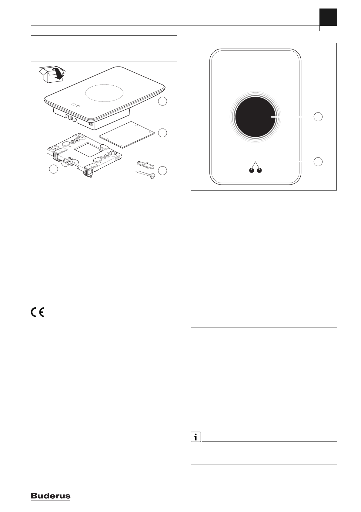
3.1 Scope of delivery
Fig. 1 Scope of delivery
[1] Logamatic TC100
[2] Quick Install Guide
[3] Screw with rawl plug 2 ×
[4] Wall plate
3.2 Accessories
The following accessories are available:
• Smart Radiator Thermostats
• Logamatic TC100 adaptor
• Logamatic TC100 app (free of charge).
Visit www.buderus-logamaticTC100.com for an up-to-date overview.
3.3 Warranty conditions
A manufacturer's warranty of 2 years is provided for Logamatic TC100.
3.4 Declaration of Conformity (Europe)
Hereby, Bosch Thermotechnik GmbH, declares that the radio
equipment with type TC100.2 are in compliance with Directive
2014/53/EU.
The complete text of the EU Declaration of Conformity is available on the
Internet: www.buderus-logamaticTC100.com/manual.
3.5 Data privacy
Information about data protection can be found on the Logamatic TC100
site under Data protection.
3.6 Data connection
▶ Logamatic TC100 supports open WLAN connections and WLAN
connections encrypted with WEP 128, WPA and WPA2 protocols.
WPA2 is the safest protocol and is therefore preferred.
▶ “Hidden” networks are not supported.
▶ Logamatic TC100 takes over the time setting of the Buderus server.
If there is no connection to the server, Logamatic TC100 can only be
put into operation in manual operation.
▶ All costs for creating an Internet connection and a smart device are to
be borne by the user.
▶ The type of connected heat source determines, which functions can
be used. Consult the Logamatic TC100 site to gain an overview of
which functions are available for which heat source.
1)
1)
3.7 Proximity sensor and touch screen
2
1
0010018148-001
Fig. 2 Proximity sensor and touch screen
[1] Proximity sensor
[2] Touch screen
A proximity sensor [1] detects a presence in front of the touch screen
[2] and lights up. If nothing more is detected for a short period of time,
the touch screen automatically switches off. If the detection lasts for
longer than 5 minutes, the touch screen automatically switches off.
▶ If required, clean the touch screen with a clean, dry cloth.
3.8 Ambient Light
Logamatic TC100 not only communicates with you via the app, but also
via Ambient Light. As soon as you send a heating command via the app to
Logamatic TC100, it lights orange for a second when you increase the
temperature, and blue when you lower the temperature. When you leave
your home, a green light for a second indicates that the heating system
has automatically switched to away mode. Red light: Error occurred in
your heating system. If everything is running normally, Ambient Light will
be off.
4 Assembly
4.1 Prior to installation
▶ Prior to installation, check that Logamatic TC100 can be combined
with the heat source.
On the Logamatic TC100 site there is a list of possible combinations with
or without the operation of Logamatic TC100.
Minimum requirements for installation:
▶ 2-wire cable to a heat source, which is suitable for use with Logamatic
TC100.
▶ Broadband internet access via WLAN 802.11 b/g (2.4 GHz) for use
with the app and internet functions.
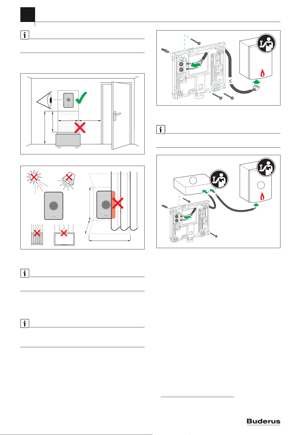
4.2 Determining the installation location
A reference room is a room (for example the living room), where the
temperature, which is representative of the whole dwelling, is measured,
and where most time is spent.
1)
1) See the back of this document for the web address.
Logamatic TC100 – 6720889234 (2018/10)
3
4
0010018149-001
1,2 - 1,9 m
≥ 0,75 m
≥ 1 m
≥ 0,6 m
0010018150-001
≥ 1 m
≥ 0,4 m
≥ 0,6 m
Assembly
If weather-compensated control is used, it is not necessary to locate the
controller in the reference room.
▶ Install the controller on an internal wall in the reference room.
Ensure that there is sufficient clearance around the controller.
Fig. 3 Installation location for controller, clearance
EMS
l 100 m
0010018151-002
Fig. 5 Connecting the wall plate
4.4 Connecting to the heat source
The installation instructions for the heat source contain further
information about the connection of Logamatic TC100.
1
2
l ≤ 100 m
l ≤ 3 m
EMS BUS
Fig. 4 Installation location for controller, condition
4.3 Fitting the wall plate
When replacing a controller with Logamatic TC100, the existing wall
plate can continue to be used ( section 4.5).
This wall plate can be fastened directly to the wall, for example at the
location of the previous controller.
▶ Pull the mains plug of the heat source from the socket.
When fitting to a recessed wall box, ensure that the room temperature
measurement can not be impaired by any draughts. If required, stuff the
recessed wall box with thermal insulation material.
▶ Connect the lead (EMS-BUS connection of the heat source) to the
terminals on the wall plate. The wires can be connected in any order.
0010018152-002
Fig. 6 Connecting the Logamatic TC100 adaptor
[1] Logamatic TC100 adaptor
[2] Heat sources which use iRT, OpenTherm or On-Off
There are various possibilities for connection to a heat source:
• Replacing an existing controller on the same wall plate. Logamatic
TC100 is ready for operation.
• Buderus
• Buderus
• Heat sources, which use iRT, OpenTherm or On-Off, can only be
1)
heat source appliance with a visible orange controller
connection on the underside. Connect Logamatic TC100 with the
orange connector at the orange terminal.
1)
heat source appliance without a visible connection for the
controller. The heat source must be opened by a recognized installer.
connected with an Logamatic TC100 adaptor (accessory).
For more up-to-date information see the back of this document for
the web address or consult a recognized installer.
4
1) Or a Bosch Group brand (Nefit, Junkers, Worcester, ELM LeBlanc).
Logamatic TC100 – 6720889234 (2018/10)
 Loading...