

Buderus Logamatic SC40 Installation And Servicing Instructions
Installation and servicing
instructions
7747006071-00.1 SD
Solar thermal
controller
Logamatic SC40
7 747 017 473 GB (2007/08) OSW
For Heating Engineers
Please read carefully
prior to installation.
Contents
Contents
1 Safety instructions and explanation of symbols 3
1.1 General safety instructions 3
1.2 Symbols 4
2 Details of the product 5
2.1 EU Declaration of Conformity 5
2.2 Package contents 5
2.3 Product description 5
2.4 Specifications 6
3 Regulations 7
4 Installation (for engineers only) 8
4.1 Mounting the controller on a wall 8
4.2 Installing diverter valve for return boost (optional) 9
4.3 Fitting a heat meter (optional) 11
4.4 Electrical connections 13
5Operation 43
5.1 controller controls 43
5.2 controller operation levels 44
6 Commissioning (for engineers only) 46
6.1 Entering basic settings 47
7 Service level menu (for qualified heating engineers only) 48
7.1 Service level menu functions 48
7.2 Language selection 50
7.3 Time, setting 51
7.4 Select system 52
7.5 Settings 55
7.6 System operating mode 67
7.7 Fault diagnosis 68
7.8 Reset 69
8Faults 70
8.1 Faults indicated on the display 70
8.2 Faults not indicated on the display 71
2
Logamatic SC40 - Technical specifications are subject to change without prior notice.

Safety instructions and explanation of symbols
1
1 Safety instructions and explanation of symbols
1.1 General safety instructions
About this manual
This manual contains important information for the safe and correct installation and operation of the
solar thermal controller.
This manual is intended for heating engineers.
V Read this manual carefully and keep it for future reference.
V Always observe the safety instructions to prevent injury and damage to property.
Intended use
The solar thermal temperature difference controller (referred to from now on as the "controller") may
only be used for the operation of solar thermal systems under the specified ambient conditions
(Æ Section 2.4).
The controller must not be used outdoors, in damp rooms or in rooms where easily combustible gas
mixtures could form.
V Only operate the solar thermal system as intended and when the system is in perfect working
order.
Electrical connections
Any work that requires the controller to be opened may only be carried out by a qualified electrician.
V The electrical supply must be connected by a qualified electrician.
V Make sure that an all-pole mains isolating device compliant with EN 60335-1 for disconnection
from the power supply is fitted.
V Isolate the controller from the mains power supply before opening.
Domestic hot water temperature
V To limit the DHW outlet temperature to max. 60 °C, fit a thermostatic blending valve.
Standards and guidelines
V Ensure that installation and operation of the device conforms to the local standards and guide-
lines.
Disposal
V Dispose of packaging in an environmentally responsible manner.
V When replacing components, dispose of the old parts in an environmentally responsible manner.
Logamatic SC40 - Technical specifications are subject to change without prior notice.
3
Safety instructions and explanation of symbols
1
1.2 Symbols
Safety instructions in this document are identified by a warning-triangle symbol and
are printed on a grey background.
Hazard warnings indicate the seriousness of the consequences of not following the safety instructions.
– Caution indicates that minor damage to property could result.
– Warning indicates that minor personal injury or serious damage to property could result.
– Danger indicates that serious personal injury could result. In particularly serious cases, lives
could be at risk.
Notes are identified by the symbol shown on the left. They are bordered by horizontal
lines above and below the text.
Notes contain important information in cases where there is no risk of personal injury or damage to
property.
4
Logamatic SC40 - Technical specifications are subject to change without prior notice.
Details of the product
7747006071.06-1.SD
1
5
2 Details of the product
2.1 EU Declaration of Conformity
The design and operation of this product conform to the applicable European
directives and supplementary national requirements. Confirmity has been demonstrated. You can request a copy from your local Buderus office.
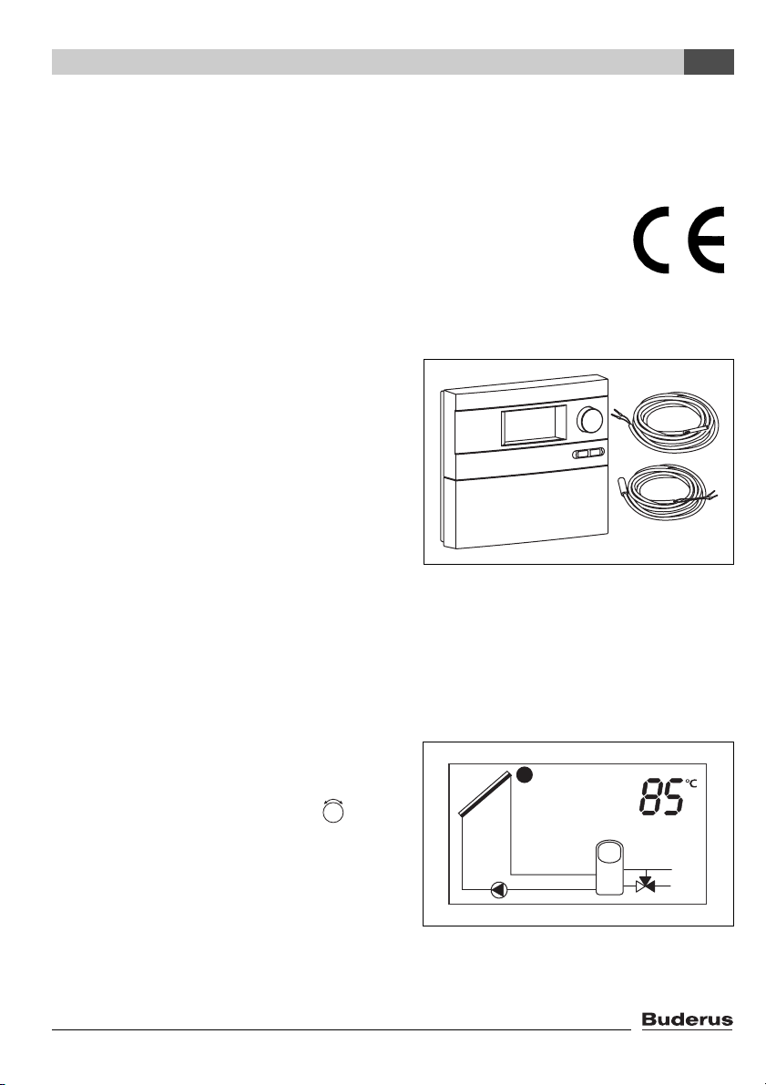
2.2 Package contents
– controller SC40
– Collector temperature sensor NTC 20K (FSK)
– Storage cylinder temperature sensor NTC 10K
– Fixings and cable clamps (for wall-mounting)
Additional components that may be required such
as temperature sensors, heat meters and valves
are available as optional accessories.
Fig. 1 Controller and temperature
sensors
2
7747006071.06-1.SD
2.3 Product description
The controller is designed for use with a solar thermal system. It can be mounted on a wall or is integrated in a solar pumping station.
In normal operating mode, the display screen on
the controller stays illuminated in green/yellow for
5 minutes after the last button was pressed (activated by pressing the rotary selector , for
example). The display shows the following:
– Pump status (as simple schematic diagram not
representative of actual system)
– System values (e.g. temperatures)
– Selected functions
– Fault messages
Logamatic SC40 - Technical specifications are subject to change without prior notice.
Fig. 2 Example of screen display
5
Details of the product
2
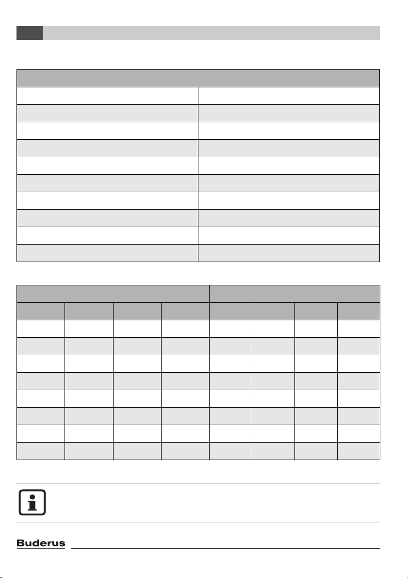
2.4 Specifications
controller SC40
Power consumption 1.8 W
Enclosure rating IP20 / DIN 40050
Supply voltage 230 V AC, 50 Hz
Operating current I
Maximum power consumption 5 A (max. 1.1 A per output/1 device per output)
Sensing range –30 °C to +180 °C
Permissible ambient temperature 0 to +50 °C
Collector temperature sensor NTC 20K with 2.5 m cable
Cylinder temperature sensor NTC 10K with 3 m cable
Dimensions H x W x D 170 x 190 x 53 mm
max
: 5 A
Tab. 1 Specifications
Temperature sensor S1 (S5 with 2 fields) NTC 20K Temperature sensor S2 ... S8 NTC 10K
T (°C) R (kΩ) T (°C) R (kΩ) T (°C) R (kΩ) T (°C) R (kΩ)
-20 198.4 60 4.943 60 2.49
-10 112.4 70 3.478 70 1.753
0 66.05 80 2.492 0 32.56 80 1.256
10 40.03 90 1.816 10 19.86 90 0.915
20 25.03 100 1.344 20 12.487 100 0.677
30 16.09 110 1.009 30 8.060 110 0.509
40 10.61 120 0.767 40 5.331 120 0.387
50 7.116 130 0.591 50 3.606 125 0.339
Tab. 2 Resistances of the temperature sensors
The temperature sensors must be disconnected from the controller for their resistances to be measured.
6
Logamatic SC40 - Technical specifications are subject to change without prior notice.

Regulations
3 Regulations
This device complies with the applicable EN requirements.
V Observe the following regulations and guidelines:
– Local regulations and requirements of the electricity supplier concerned.
– Commercial/industrial codes and regulations and fire regulations.
3
Logamatic SC40 - Technical specifications are subject to change without prior notice.
7
Installation (for engineers only)
4
4 Installation (for engineers only)
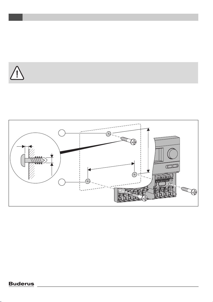
4.1 Mounting the controller on a wall
The controller is attached to the wall by three screws.
Caution: Risk of injury and damage to the casing if incorrectly mounted.
V Do not use the rear panel of the casing as a drilling template.
V Drill the upper mounting hole (Æ Fig. 3, item 1). Drive in a screw leaving the head proud by 5 mm.
Slacken the screw at the bottom of the controller and remove the cover. Hang the controller on
the wall by means of the slot in the rear panel. Mark out the lower mounting holes (Æ Fig. 3,
item 2), drill the holes and insert wall plugs. Straighten the controller and screw firmly in place
through the lower mounting holes, left and right.
1
5 mm
120 mm
166 mm
6 mm
2
Fig. 3 Mounting the controller on a wall
1 Top fixing hole
2 Bottom fixing holes
8
Logamatic SC40 - Technical specifications are subject to change without prior notice.
7747006072-01.1 SD
Installation (for engineers only)
4
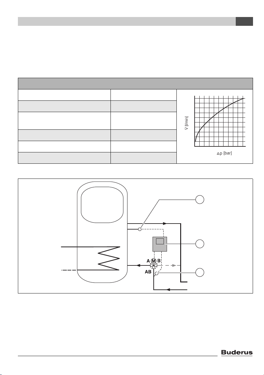
4.2 Installing diverter valve for return boost (optional)
The "return boost" function for boosting the heating system using the solar thermal system requires
a diverter valve to be fitted. The diverter valve directs the flow of central heating water either through
the thermal store or directly back to the boiler depending on the heating system's return temperature.
Specifications of diverter valve
Max. closing pressure 0.55 bar (55 kPa)
Max. static pressure 8.6 bar (860 kPa)
Max. fluid temperature 95 °C, 110 °C for short
periods
kV rating 8.2
Voltage 230 V, 50 Hz
Maximum ambient temperature 50 °C
100
90
80
70
60
50
40
30
20
10
Tab. 3 Specifications and pressure loss characteristics of diverter valve
7747006072-03.1 SD
RK
RL
Fig. 4 Installation diagram for combination cylinder return boost
1 Cylinder temperature sensor S6
2 Solar thermal controller Logamatic SC40
3 Return temperature sensor S3
RL Heating return
RK Boiler return
0,1 0,2 0,3 0,4 0,5
1
2
3
Logamatic SC40 - Technical specifications are subject to change without prior notice.
9
Installation (for engineers only)
4
Observe the connection markings on the diverter valve.The valve in Fig. 4 allows fluid
to flow from AB to B when de-energised. Once the set temperature difference is
reached, the valve switches over to divert the flow from AB to A.
Caution: Risk of system damage if the valve positioner casing is damaged.
V Use spanner on union nuts not on valve body.
V Fit the diverter valve in the return pipe between the solar storage cylinder (Æ Fig. 4) and the
boiler.
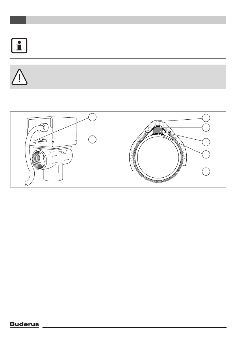
1
3
4
2
5
6
7
7747004985.10-1.SD
Fig. 5 Diverter valve (left) and fitted temperature sensor (right)
Function of valve switch
Use the "MAN" (manual, Æ Fig. 5, item 2) setting for filling, bleeding or draining the system or as
the safety setting when there is a power failure. In the "MAN" position, the valve actuator is in the
centre position. This allows even flow of the fluid through both outlet connections.
V For normal operation, set the switch to "AUTO" (Æ Fig. 5, item 1).
Installing the temperature sensors
There are 2 temperature sensors supplied with the valve. They can be used as cylinder temperature
sensors or pipe contact sensors (Æ Table 1, page 6).
V Apply heat conducting paste (Æ Fig. 5, item 6) to temperature sensor S3 (Æ Fig. 5, item 5).
V Fit temperature sensor S3 using retaining plate (Æ Fig. 5, item 4) and spring strap (Æ Fig. 5, item
7) to the return pipe approx. 20 cm upstream of the diverter valve.
V Provide temperature sensor S3 with insulation at least 20 cm long (Æ Fig. 5, item 3).
V Fit temperature sensor S6 in the position provided on the cylinder (see installation instructions
for cylinder).
10
Logamatic SC40 - Technical specifications are subject to change without prior notice.
Installation (for engineers only)
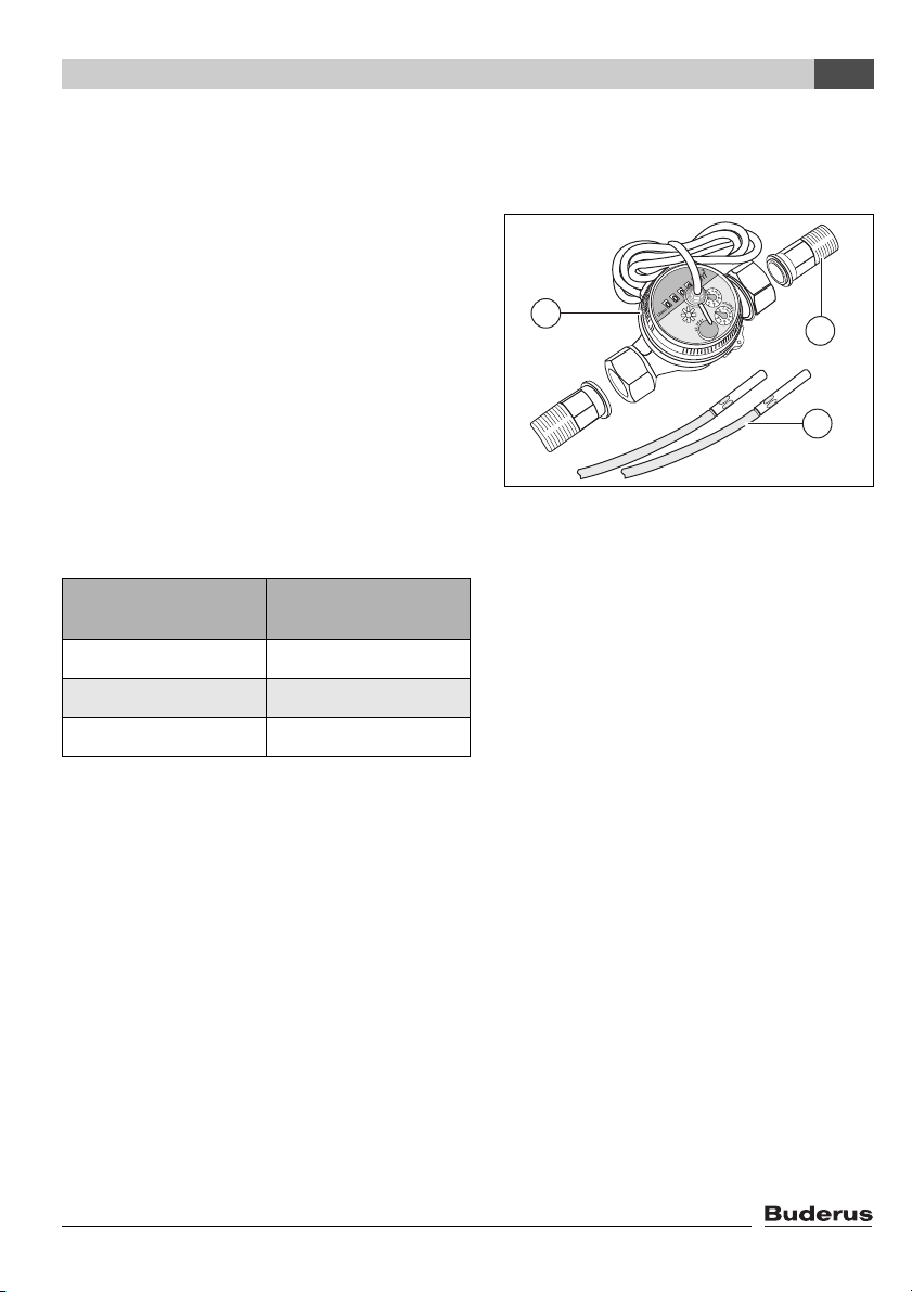
4.3 Fitting a heat meter (optional)
The heat meter gives an approximation of the heat gained from the solar panels.
Included in delivery:
– Item 1: water meter connections, ¾" inc. seals
(2 off)
– Item 2: temperature sensor NTC 10K inc. fix-
ings (2 off)
– Item 3: volumetric flow meter (1 off)
Tab. 4
Rated volumetric
Number of collectors
1 - 5 0.6 m³/h
6 - 10 1.0 m³/h
flow rate
3
Fig. 6 Heat meter
4
1
2
7747006072-33.1 SD
11 - 15 1.5 m³/h
Tab. 5 Rated volumetric flow rate
Logamatic SC40 - Technical specifications are subject to change without prior notice.
11
Installation (for engineers only)
4
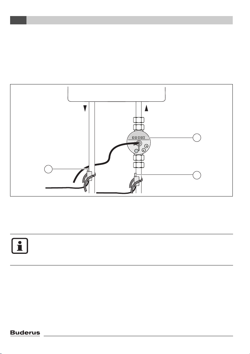
V Fit volumetric flow meter below the solar pumping station in the solar return pipe (Æ Fig. 7,
item 1). Pay attention to direction of flow and fitted position (meter dial must not face downwards).
V Fix temperature sensor for solar return (Æ Fig. 7, item 2) in position. For details of temperature
sensor fixing, refer to page 10, Fig. 5.
V Fix temperature sensor for solar flow (Æ Fig. 7, item 3) in position. For details of temperature sen-
sor fixing, refer to page 10, Fig. 5.
1
3
2
7747006072-34.1 SD
Fig. 7 Fitting the volumetric flow meter and temperature sensors
1 Volumetric flow meter
2 Return temperature sensor
3 Flow temperature sensor
The heat meter is used only to check system function. It is not capable of metering to
EN 1434 or determining yield. Calculation of yield requires a device with a calibration
certificate, usage data (water volume, room heating heat requirement), weather data
and system simulation.
V Wire up electrical connections as shown in Section 4.4.
12
Logamatic SC40 - Technical specifications are subject to change without prior notice.
Installation (for engineers only)
4
4.4 Electrical connections
Danger: risk of electric shock.
V Disconnect the power supply (230 V AC) before opening up the controller.
V Secure the cable with the cable grip.
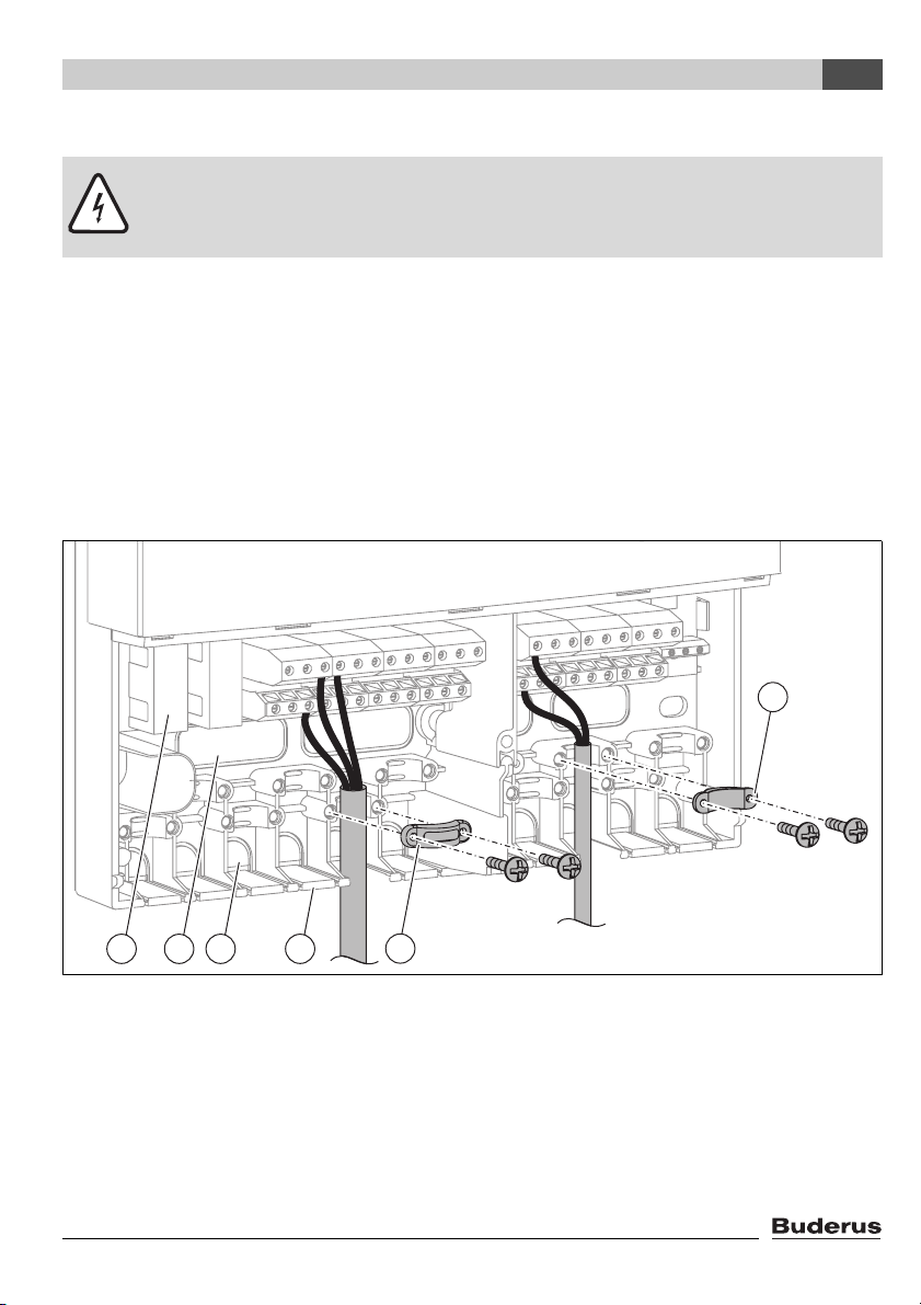
4.4.1 Preparing cable entry
The cables can be fed into the housing from behind (Æ Fig. 8, item 4) or from below (Æ Fig. 8,
item 3).
V Maintain IP 20 protection when installing:
– Cut open only the cable entries required.
– Cut open the cable entry only as much as required.
V To avoid jagged edges, cut out the cable entries with a knife (Æ Fig. 8).
V Secure cables with the appropriate cable grips (Æ Fig. 8, item 2). The strain relief clamp can also
be fitted in the reverse position (Æ Fig. 8, item 1).
1
4
5 4
Fig. 8 Feeding in and securing cables
1 Cable grip reversed
2 Cable grip
3 Cable entry from below
4 Cable entry from the rear
5 Fuse, 2.5 A slow (2 off)
Logamatic SC40 - Technical specifications are subject to change without prior notice.
3
2
7747006072-02.1 SD
13
Installation (for engineers only)
4
4.4.2 Connecting the leads
Observe the following when connecting the cables:
– Comply with local regulations, such as protective earthing tests etc.
– Only use pumps, valves and sensors supplied by Buderus.
– Protect the controller from overloads and short-circuits.
– The power supply must match the specifications on the rating plate. See also Table 1, page 6.
2
– Connect only 1 lead to each terminal (max. 1.5 mm
– The temperature sensor leads can be connected either way round. The sensor leads can be up
to 100 metres long (up to 50 m length = 0.75 mm
).
2
, up to 100 m = 1.5 mm2).
– Route all sensor leads separately from cables carrying 230 V or 400 V to avoid inductive inter-
ference (minimum separation 100 mm).
– Use shielded low-voltage cables if external inductive interference is expected (e.g. from power
substations, high-voltage power cables, microwaves).
– For the 230 V connection, use a cable of at least type H05 VV- ... (NYM...).
– Ensure that structural fire safety features are not impaired.
– The leads from the motorised diverter valves shown in the configuration diagrams must be con-
nected as follows: brown = R, blue = N, yellow and green = Earth.
– Only connect pumps to the outputs R1 and R2 (speed control on these connections only).
– Motorised valves with OPEN/CLOSE command (or mixer units) must also be connected to ter-
minals to .
R3
R5
– The connections L3 to L5 are for the power supply for special functions of connected compo-
nents.
The use of some functions (double match flow, cooling, daily heating and heat exchanger anti-icing) requires additional components (valves, temperature sensors) that
must be purchased separately (Æ Table 13, page 53).
Warning: risk of damage to system due to pump failure.
V If a pump with internal electronic control circuitry is to be connected, deactivate the
speed modulation function (Æ Section 7.5.2, page 56).
V Connect the leads according to the desired configuration diagram (Æ pages 15 - 41).
V After completing the work, close the controller by replacing the cover and tightening the securing
screw.
14
Logamatic SC40 - Technical specifications are subject to change without prior notice.
Installation (for engineers only)
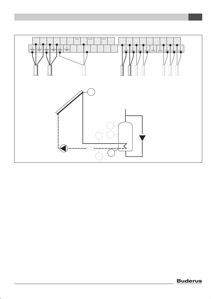
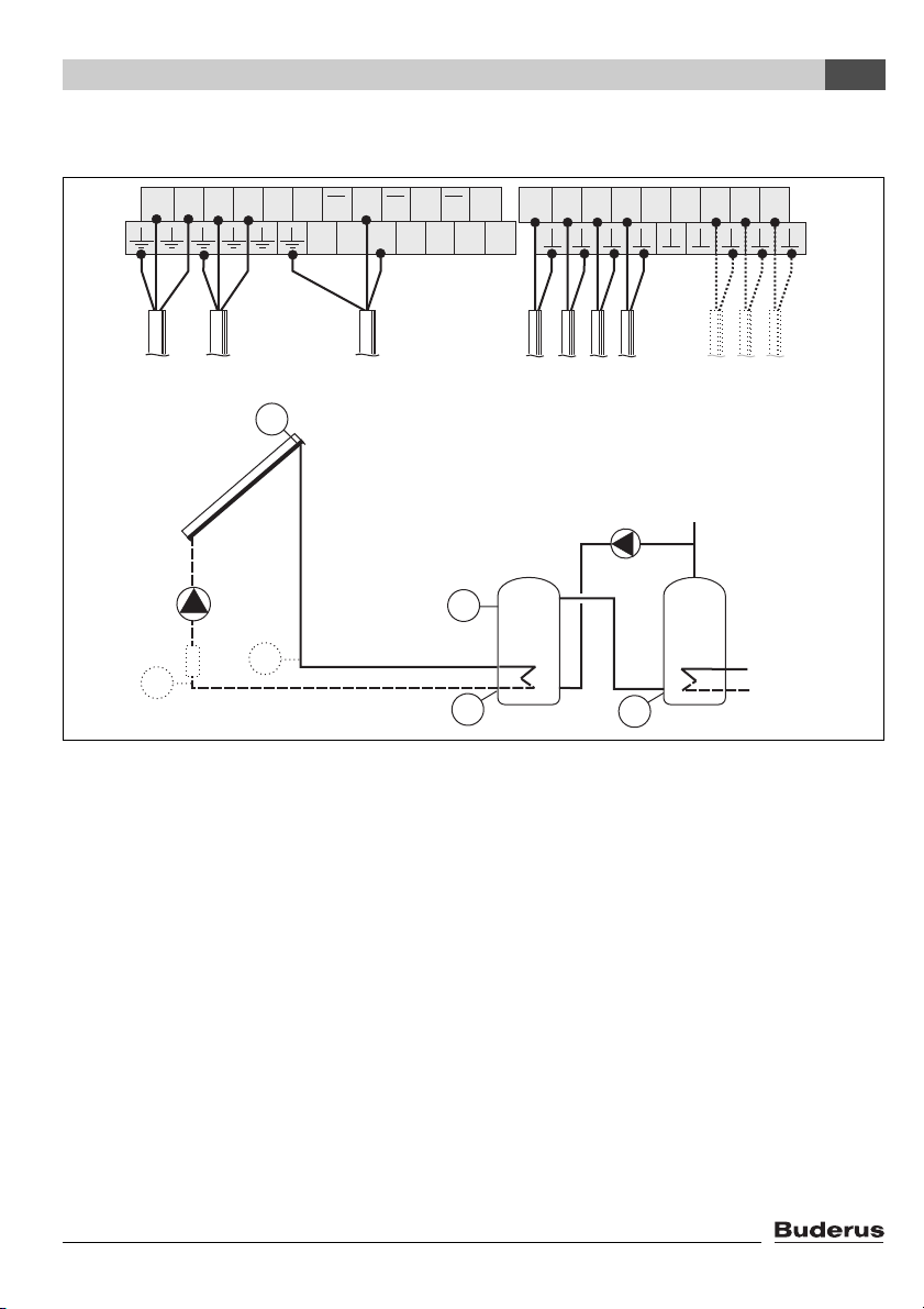
4.4.3 Configuration diagram T1 - domestic water heating
4
L NR1N1R2N2R3R3R4R4R5R5
L3 N3 L4 N4 L5 N5
230V
AC
R1
R3
S1 S2 S3 S4 S5 S6 S7 S8 I9
S1 S2 S3 S7 S8
S1
S3
S4
S7
R1
S8
S2
WMZ
Fig. 9
R1 Solar circuit pump 1
R3 Daily heating pump (optional)
S1 Collector temperature sensor FSK
S2 Cylinder bottom temperature sensor
S3 Cylinder top temperature sensor (optional)
S4 Cylinder centre temperature sensor (optional)
S7 Flow heat meter WMZ temperature sensor (optional)
S8 Return heat meter temperature sensor (optional)
WMZ Heat meter (optional)
S4
WMZ
R3
7747006072-04.1 SD
Logamatic SC40 - Technical specifications are subject to change without prior notice.
15
Installation (for engineers only)
4
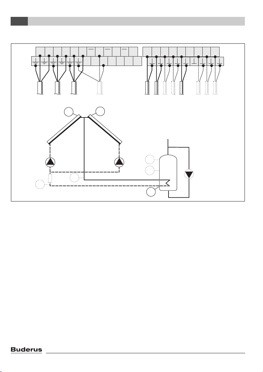
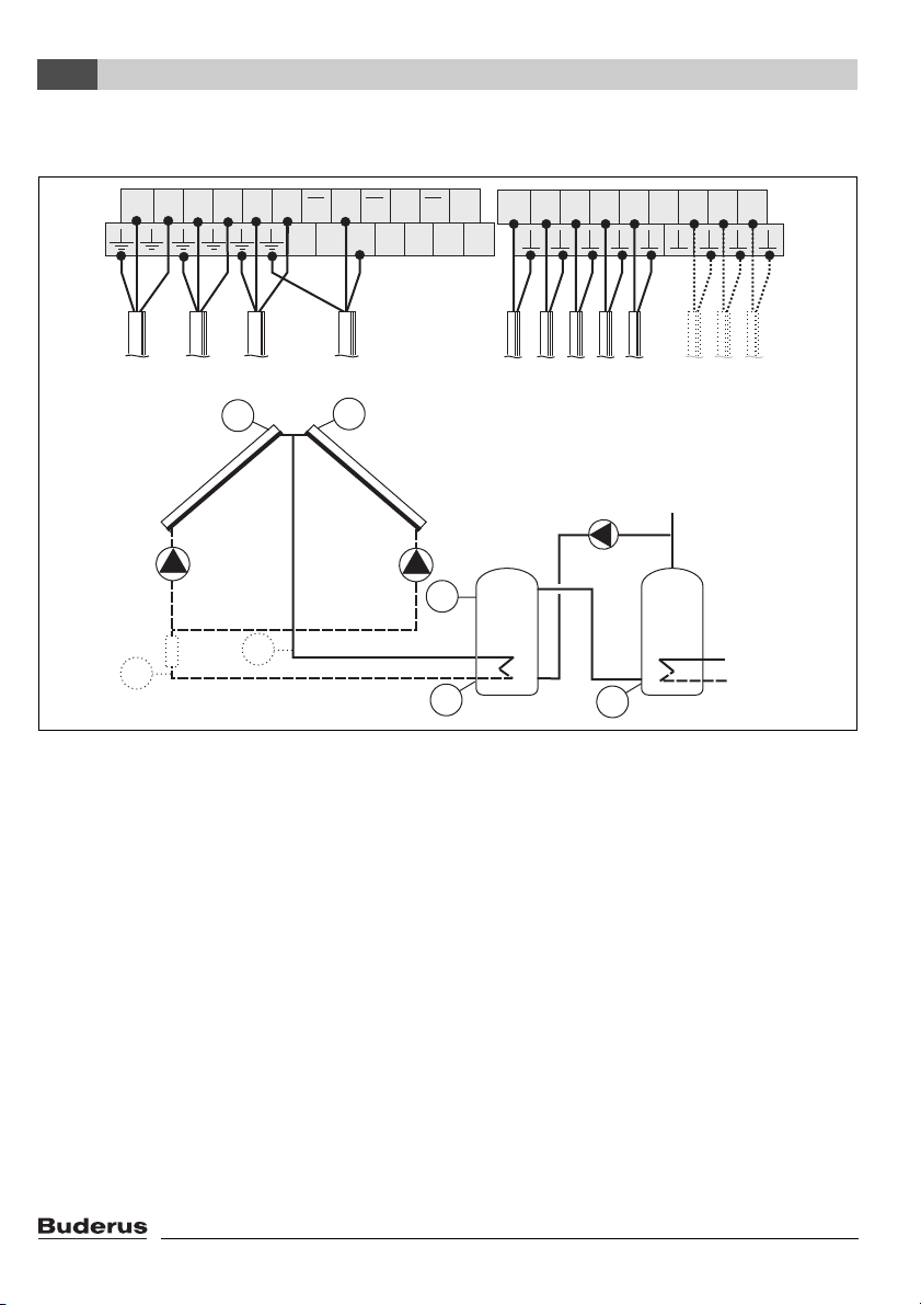
4.4.4 Configuration diagram T2 - solar water heating with East/West aspect function
L NR1N1R2N2R3R3R4R4R5R5
L3 N3 L4 N4 L5 N5
230V
AC
R1
S1
R2R1
R3
S5
R2
S1 S2 S3 S4 S5 S6 S7 S8 I9
S1 S2 S3 S5 S7 S8
S3
S4
WMZ
S7
S8
S2
Fig. 10
R1 Solar circuit pump 1
R2 Solar circuit pump 2
R3 Daily heating pump (optional)
S1 Collector temperature sensor FSK, field 1
S2 Cylinder bottom temperature sensor
S3 Cylinder top temperature sensor (optional)
S4 Cylinder centre temperature sensor (optional)
S5 Collector temperature sensor FSK, field 2
S7 Flow heat meter WMZ temperature sensor (optional)
S8 Return heat meter temperature sensor (optional)
WMZ Heat meter (optional)
S4
WMZ
R3
7747006072-05.1 SD
16
Logamatic SC40 - Technical specifications are subject to change without prior notice.
Installation (for engineers only)
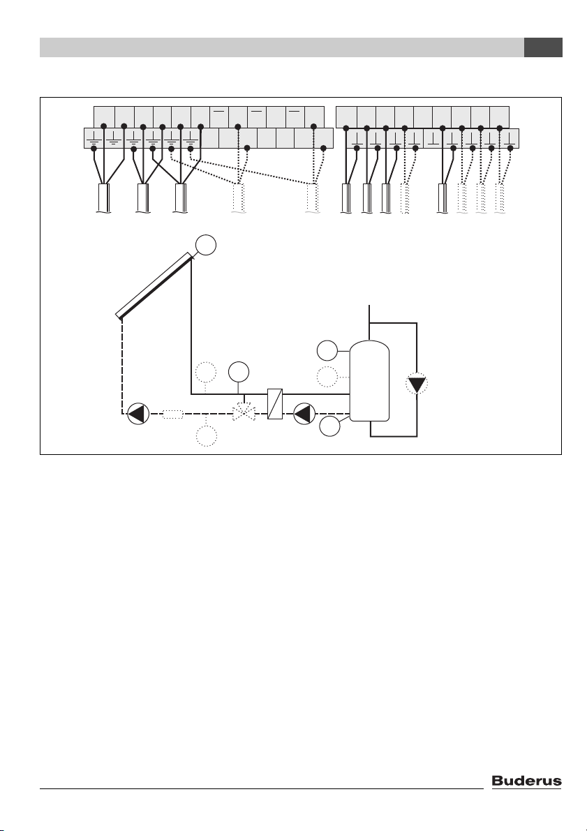
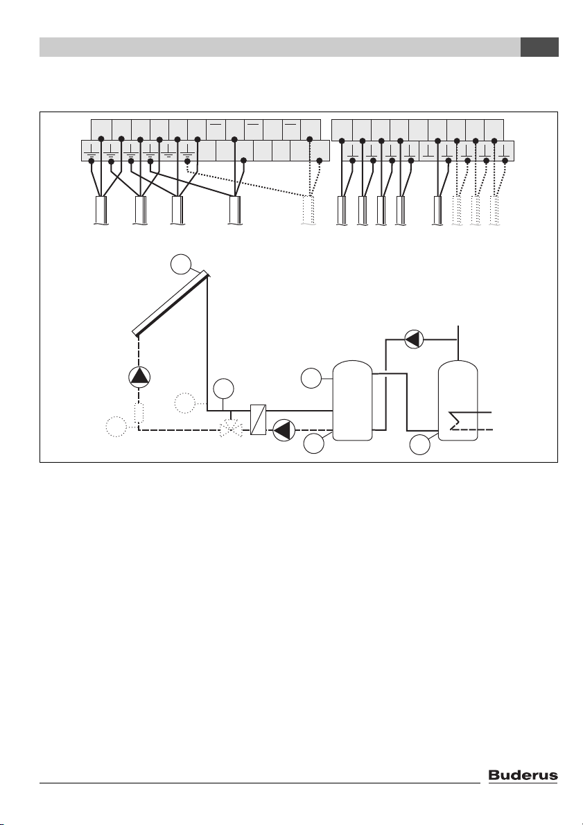
4.4.5 Configuration diagram T3 - solar water heating with external heat exchanger
4
L NR1N1R2N2R3R3R4R4R5R5
L3 N3 L4 N4 L5 N5
230V
AC
R3
S1
S1 S2 S3 S4 S5 S6 S7 S8 I9
R5R2R1
S1 S2 S3 S6 S7S8
S4
S3
S6
R1
WMZ
S7
S8
R5
R2
S4
S2
Fig. 11
R1 Solar circuit pump 1
R2 Heat exchanger pump
R3 Daily heating pump (optional)
R5 Anti-icing system valve (optional)
S1 Collector temperature sensor FSK
S2 Cylinder bottom temperature sensor
S3 Cylinder top temperature sensor (required for shutdown at 95 °C)
S4 Cylinder centre temperature sensor (optional)
S6 Temperature sensor for external heat exchanger
S7 Flow heat meter WMZ temperature sensor (optional)
S8 Return heat meter temperature sensor (optional)
WMZ Heat meter (optional)
WMZ
R3
7747006072-06.1 SD
Logamatic SC40 - Technical specifications are subject to change without prior notice.
17
Installation (for engineers only)
Z
4
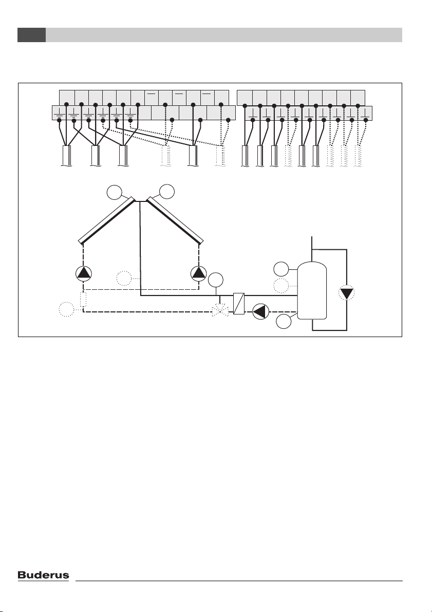
4.4.6 Configuration diagram T4 - solar water heating with external heat exchanger and
East/West aspect function
L NR1N1R2N2R3R3R4R4R5R5
L3 N3 L4 N4 L5 N5
230V
R4R3R5R2R1
S1 S2 S3 S4 S5 S6 S7 S8 I9
S1 S2 S3 S5 S6 S7S8
S4
AC
S1
R1
S7
S5
R4
S6
S3
S4
WMZ
S8
7747006072-07.1 SD
R5
R2
S2
Fig. 12
R1 Solar circuit pump 1
R2 Heat exchanger pump
R3 Daily heating pump (optional)
R4 Solar circuit pump 2
R5 Anti-icing system valve (optional)
S1 Collector temperature sensor FSK, field 1
S2 Cylinder bottom temperature sensor
S3 Cylinder top temperature sensor (required for shutdown at 95 °C)
S4 Cylinder centre temperature sensor (optional)
S5 Collector temperature sensor FSK, field 2
S6 Temperature sensor for external heat exchanger
S7 Flow heat meter WMZ temperature sensor (optional)
S8 Heat meter WMZ return temperature sensor (optional)
WMZ Heat meter (optional)
WM
R3
18
Logamatic SC40 - Technical specifications are subject to change without prior notice.
Installation (for engineers only)
4.4.7 Configuration diagram T5 - solar water heating with preheating stage charge transfer
4
L NR1N1R2N2R3R3R4R4R5R5
L3 N3 L4 N4 L5 N5
230V
AC
R1
R3
S1 S2 S3 S4 S5 S6 S7 S8 I9
S1 S2 S3 S4 S7 S8
S1
WMZ
R1
S7
S3
S8
7747006072-08.1 SD
S2
Fig. 13
R1 Solar circuit pump 1
R3 Charge transfer pump
S1 Collector temperature sensor FSK
S2 Cylinder 1 bottom temperature sensor
S3 Cylinder 1 top temperature sensor
S4 Cylinder 2 bottom temperature sensor
S7 Flow heat meter WMZ temperature sensor (optional)
S8 Return heat meter temperature sensor (optional)
WMZ Heat meter (optional)
WMZ
R3
S4
Logamatic SC40 - Technical specifications are subject to change without prior notice.
19
Installation (for engineers only)
4
4.4.8 Configuration diagram T6 - solar water heating with East/West aspect function and preheating stage charge transfer
L NR1N1R2N2R3R3R4R4R5R5
L3 N3 L4 N4 L5 N5
230V
AC
R1
S1
R2R1
R3
S5
R2
S1 S2 S3 S4 S5 S6 S7 S8 I9
S1 S2 S3 S4 S5 S7 S8
S3
WMZ
S7
S8
7747006072-09.1 SD
S2
Fig. 14
R1 Solar circuit pump 1
R2 Solar circuit pump 2
R3 Charge transfer pump
S1 Collector temperature sensor FSK, field 1
S2 Cylinder 1 bottom temperature sensor
S3 Cylinder 1 top temperature sensor
S4 Cylinder 2 bottom temperature sensor
S5 Collector temperature sensor FSK, field 2
S7 Flow heat meter WMZ temperature sensor (optional)
S8 Return heat meter temperature sensor (optional)
WMZ Heat meter (optional)
WMZ
R3
S4
20
Logamatic SC40 - Technical specifications are subject to change without prior notice.
Installation (for engineers only)
4.4.9 Configuration diagram T7 - solar water heating with preheating stage charge transfer and external heat exchanger
4
L NR1N1R2N2R3R3R4R4R5R5
L3 N3 L4 N4 L5 N5
230V
R3
S1 S2 S3 S4 S5 S6 S7 S8 I9
R5R2R1
S1 S2 S3 S4 S6 S7S8
AC
S1
R1
S3
S6
WMZ
S7
S8
7747006072-29.1 SD
R5
R2
S2
Fig. 15
R1 Solar circuit pump 1
R2 Heat exchanger pump
R3 Charge transfer pump
R5 Anti-icing system valve (optional)
S1 Collector temperature sensor FSK
S2 Cylinder 1 bottom temperature sensor
S3 Cylinder 1 top temperature sensor
S4 Cylinder 2 bottom temperature sensor
S6 Temperature sensor for external heat exchanger
S7 Flow heat meter WMZ temperature sensor (optional)
S8 Return heat meter temperature sensor (optional)
WMZ Heat meter (optional)
WMZ
R3
S4
Logamatic SC40 - Technical specifications are subject to change without prior notice.
21

Installation (for engineers only)
4
4.4.10 Configuration diagram T8 - solar water heating with East/West aspect function, preheating stage charge transfer and external heat exchanger
L NR1N1R2N2R3R3R4R4R5R5
L3 N3 L4 N4 L5 N5
230V
R4R3R5R2R1
S1 S2 S3 S4 S5 S6 S7 S8 I9
S1 S2 S3 S4 S5 S6 S7S8
AC
S1
S5
S7
R1
R4
S3
S6
WMZ
S8
7747006072-30.1 SD
R5
R2
Fig. 16
R1 Solar circuit pump 1
R2 Heat exchanger pump
R3 Charge transfer pump
R4 Solar circuit pump 2
R5 Anti-icing system valve (optional)
S1 Collector temperature sensor FSK, field 1
S2 Cylinder 1 bottom temperature sensor
S3 Cylinder 1 top temperature sensor
S4 Cylinder 2 bottom temperature sensor
S5 Collector temperature sensor FSK, field 2
S6 Temperature sensor for external heat exchanger
S7 Flow heat meter WMZ temperature sensor (optional)
S8 Return heat meter temperature sensor (optional)
WMZ Heat meter (optional)
S2
WMZ
R3
S4
22
Logamatic SC40 - Technical specifications are subject to change without prior notice.
 Loading...