

Buderus Logamatic LON-Gateway Technical Information
Technical Information
Interface with DDC
6 720 642 841-00.1RS
Logamatic LON-Gateway
6 720 643 554 (01/2010) US/CA
For heating contractors
during project planning.
Contents
Contents
1 Explanation of symbols and safety instructions . . . . . . . . . . . . . . . . . . . . . . . . . . . . . . . 4
1.1 Guideline to symbols . . . . . . . . . . . . . . . . . . . . . . . . . . . . . . . . . . . . . . . . . . . . . . . . . . . . . . 4
1.2 Safety instructions . . . . . . . . . . . . . . . . . . . . . . . . . . . . . . . . . . . . . . . . . . . . . . . . . . . . . . . . 5
2 Product description . . . . . . . . . . . . . . . . . . . . . . . . . . . . . . . . . . . . . . . . . . . . . . . . . . . . . . . . 6
2.1 Correct use . . . . . . . . . . . . . . . . . . . . . . . . . . . . . . . . . . . . . . . . . . . . . . . . . . . . . . . . . . . . . . 6
2.2 Disposal . . . . . . . . . . . . . . . . . . . . . . . . . . . . . . . . . . . . . . . . . . . . . . . . . . . . . . . . . . . . . . . . . 6
2.3 Product description . . . . . . . . . . . . . . . . . . . . . . . . . . . . . . . . . . . . . . . . . . . . . . . . . . . . . . . 7
2.4 Specifications . . . . . . . . . . . . . . . . . . . . . . . . . . . . . . . . . . . . . . . . . . . . . . . . . . . . . . . . . . . . 8
2.5 Specified communication objects . . . . . . . . . . . . . . . . . . . . . . . . . . . . . . . . . . . . . . . . . . . . 8
2.6 Logamatic LON-Gateway firmware . . . . . . . . . . . . . . . . . . . . . . . . . . . . . . . . . . . . . . . . . . 10
2.6.1 Firmware when delivered . . . . . . . . . . . . . . . . . . . . . . . . . . . . . . . . . . . . . . . . . . . . . . . . . . 10
2.6.2 Procedure for updating firmware . . . . . . . . . . . . . . . . . . . . . . . . . . . . . . . . . . . . . . . . . . . . 10
3 Network interface . . . . . . . . . . . . . . . . . . . . . . . . . . . . . . . . . . . . . . . . . . . . . . . . . . . . . . . . . 11
3.1 Overview of the SNVTs for variant 2 boilers . . . . . . . . . . . . . . . . . . . . . . . . . . . . . . . . . . 11
3.2 Description of the SNVTs for variant 2 boilers . . . . . . . . . . . . . . . . . . . . . . . . . . . . . . . . . 14
3.2.1 General . . . . . . . . . . . . . . . . . . . . . . . . . . . . . . . . . . . . . . . . . . . . . . . . . . . . . . . . . . . . . . . . 14
3.2.2 Heating zones . . . . . . . . . . . . . . . . . . . . . . . . . . . . . . . . . . . . . . . . . . . . . . . . . . . . . . . . . . . 16
3.2.3 DHW heating . . . . . . . . . . . . . . . . . . . . . . . . . . . . . . . . . . . . . . . . . . . . . . . . . . . . . . . . . . . 18
3.2.4 Strategy . . . . . . . . . . . . . . . . . . . . . . . . . . . . . . . . . . . . . . . . . . . . . . . . . . . . . . . . . . . . . . . . 20
3.2.5 Floor-standing boilers . . . . . . . . . . . . . . . . . . . . . . . . . . . . . . . . . . . . . . . . . . . . . . . . . . . . . 21
3.2.6 Solar . . . . . . . . . . . . . . . . . . . . . . . . . . . . . . . . . . . . . . . . . . . . . . . . . . . . . . . . . . . . . . . . . . . 22
3.3 Overview of the SNVTs for variant 4 boilers . . . . . . . . . . . . . . . . . . . . . . . . . . . . . . . . . . 23
3.4 Description of the SNVTs for variant 4 boilers . . . . . . . . . . . . . . . . . . . . . . . . . . . . . . . . . 26
3.4.1 General . . . . . . . . . . . . . . . . . . . . . . . . . . . . . . . . . . . . . . . . . . . . . . . . . . . . . . . . . . . . . . . . 26
3.4.2 Heating zones . . . . . . . . . . . . . . . . . . . . . . . . . . . . . . . . . . . . . . . . . . . . . . . . . . . . . . . . . . . 28
3.4.3 DHW heating . . . . . . . . . . . . . . . . . . . . . . . . . . . . . . . . . . . . . . . . . . . . . . . . . . . . . . . . . . . 30
3.4.4 Strategy . . . . . . . . . . . . . . . . . . . . . . . . . . . . . . . . . . . . . . . . . . . . . . . . . . . . . . . . . . . . . . . . 32
3.4.5 Boiler 1 . . . . . . . . . . . . . . . . . . . . . . . . . . . . . . . . . . . . . . . . . . . . . . . . . . . . . . . . . . . . . . . . 33
3.4.6 Boiler 2 . . . . . . . . . . . . . . . . . . . . . . . . . . . . . . . . . . . . . . . . . . . . . . . . . . . . . . . . . . . . . . . . 35
3.4.7 Status . . . . . . . . . . . . . . . . . . . . . . . . . . . . . . . . . . . . . . . . . . . . . . . . . . . . . . . . . . . . . . . . . 37
4 Operating basics . . . . . . . . . . . . . . . . . . . . . . . . . . . . . . . . . . . . . . . . . . . . . . . . . . . . . . . . . . 38
2
Technical Information Logamatic LON-Gateway - Subject to modifications resulting from technical improvements!

Contents
5 Incorporation of Logamatic 4000 in LON networks via Logamatic LON-Gateway . 39
5.1 Structure of the hardware . . . . . . . . . . . . . . . . . . . . . . . . . . . . . . . . . . . . . . . . . . . . . . . . . . 39
5.2 Creating LON networks . . . . . . . . . . . . . . . . . . . . . . . . . . . . . . . . . . . . . . . . . . . . . . . . . . . 39
5.2.1 Commissioning LON networks . . . . . . . . . . . . . . . . . . . . . . . . . . . . . . . . . . . . . . . . . . . . . 40
5.2.2 Decommissioning LON networks . . . . . . . . . . . . . . . . . . . . . . . . . . . . . . . . . . . . . . . . . . . 40
6 The LON-Gateway as LonMark object . . . . . . . . . . . . . . . . . . . . . . . . . . . . . . . . . . . . . . . 41
6.1 Variant 2 boiler . . . . . . . . . . . . . . . . . . . . . . . . . . . . . . . . . . . . . . . . . . . . . . . . . . . . . . . . . . . 41
6.2 Variant 4 boiler . . . . . . . . . . . . . . . . . . . . . . . . . . . . . . . . . . . . . . . . . . . . . . . . . . . . . . . . . . . 42
7 Error list . . . . . . . . . . . . . . . . . . . . . . . . . . . . . . . . . . . . . . . . . . . . . . . . . . . . . . . . . . . . . . . . . 43
Technical Information Logamatic LON-Gateway - Subject to modifications resulting from technical improvements!
3

Explanation of symbols and safety instructions
1
1 Explanation of symbols and safety instructions
1.1 Guideline to symbols
Warnings
Warnings are indicated in the text by a warning triangle and a gray background.
In case of danger from electric shock, the exclamation point on the warning triangle is
replaced with a lightning symbol.
Signal words at the beginning of a warning are used to indicate the type and seriousness of the
ensuing risk if measures for minimizing damage are not taken.
• NOTE indicates that minor damage to property may occur.
• CAUTION indicates possible minor to medium personal injury.
• WARNING indicates possible severe personal injury.
• DANGER indicates that severe personal injury may occur.
Important information
Important information that presents no risk to people or property is indicated with this
symbol. It is separated by horizontal lines above and below the text.
Additional symbols
Symbol Meaning
B Sequence of steps
Æ Cross-reference to other points in this document or to other documents
• Listing/list entry
– Listing/list entry (2nd level)
Tab. 1
4
Technical Information Logamatic LON-Gateway - Subject to modifications resulting from technical improvements!
Explanation of symbols and safety instructions
1
WARNING: Only transformers with following specification are permitted:
6 V AC; 400 mA. The transformer is not part of the product! Please take care to use a
reliable product which meets our requirements shown above. Do not mount the
transformer internally!
Buderus does not accept responsibility for systems which contravene the Installation
instruction or addition documentation in scope of delivery.
The transformer must be mounted in a separate enclosure which is rated for this purpose.
1.2 Safety instructions
Installation and commissioning
The Logamatic LON-Gateway interface module has been designed and built in accordance with
currently recognized standards and safety requirements.
However, dangers or property damage may arise if it is used improperly.
B Observe these instructions to ensure satisfactory operation.
B The appliance may only be installed and started up by a trained installer.
B All changes and adjustments made via superior control systems must meet the heating system
requirements.
Risk of death from electric shock
B The power supply must be connected by a qualified electrician.
B The terminal diagram must be followed.
B Before opening the appliance, isolate all poles of the mains power supply and secure against
unintentional reconnection.
B Never install this appliance in wet rooms.
B Ensure that a circuit breaker is available to disconnect all poles from the mains power supply.
If there is no circuit breaker, you will need to install one.
Risk of damage from operator error
Operator errors can cause injury and damage to property.
B Ensure that children never operate this appliance unsupervised or play with it.
B Ensure that only individuals who can operate this appliance correctly have access to it.
Device damage from electrostatic discharge (ESD)
B Before unpacking the module, touch a radiator or a grounded metal water pipe to discharge any
electrostatic charge in your body.
Damage from incorrect spare parts
B Only use original Buderus spare parts. Damage caused by the use of spare parts not supplied
by Buderus are excluded from the Buderus warranty.
Technical Information Logamatic LON-Gateway - Subject to modifications resulting from technical improvements!
5

Product description
2
2 Product description
2.1 Correct use
The Logamatic LON-Gateway may only be used to connect Buderus boilers with control panel from
the Buderus Logamatic 4000 control series to superior control and/or building control systems via
LON-BUS.
2.2 Disposal
B Electronic components do not belong in household waste.
Dispose of defunct modules correctly through an authorized disposal site.
6
Technical Information Logamatic LON-Gateway - Subject to modifications resulting from technical improvements!
Product description
2
2.3 Product description
The Logamatic LON-Gateway is incorporated into a LON network via a twisted pair cable (twisted
2-wire line). The twisted pair cable is protected against reverse polarity.
Defined data of the Buderus control panel is implemented with the Logamatic LON-Gateway
interface on standard network variable types (SNVTs) for the LON data bus. The communication
includes forwarding of error messages, operating messages, and actual values, as well as changing
of set points and operating modes for boilers and consumers.
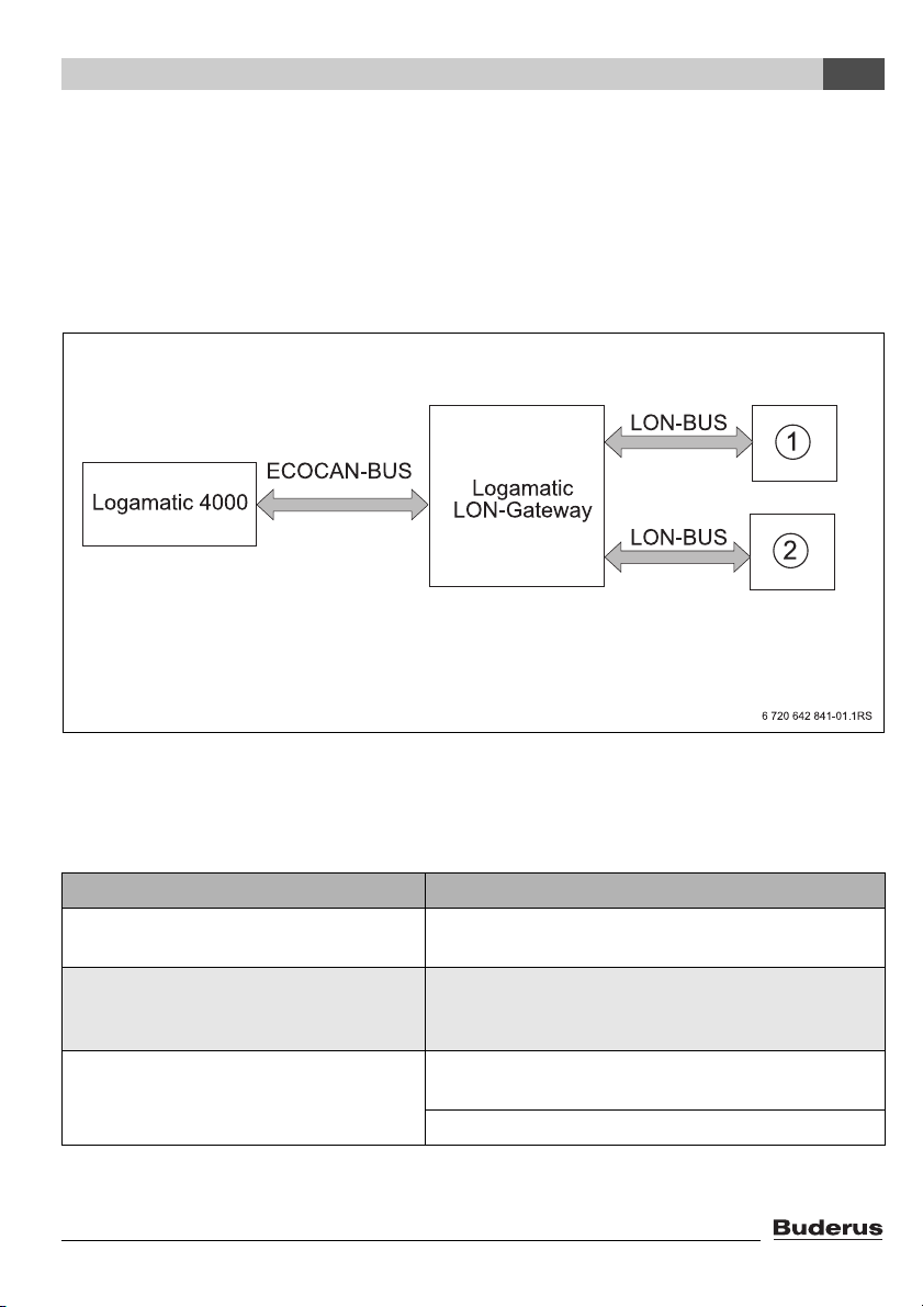
Fig. 1 Block diagram
1 Superior control system (building control system)
2 LON Gateway
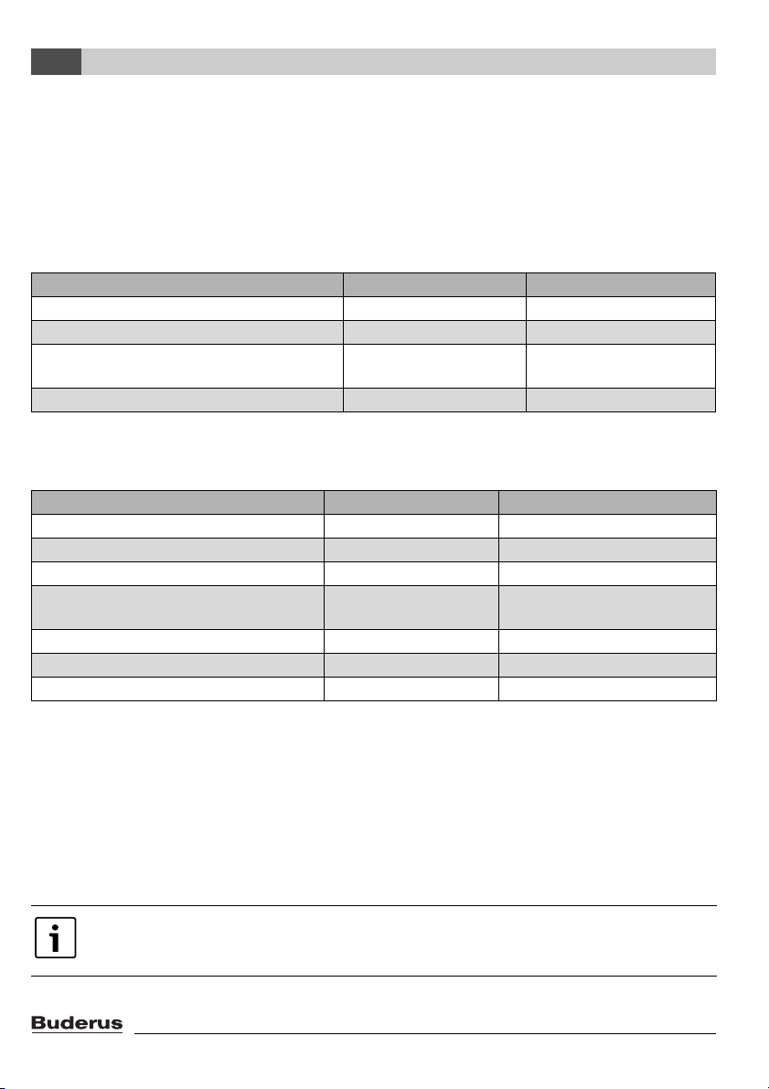
Making the electrical connections
Logamatic LON-Gateway
Connection of the Logamatic LON-Gateway
with Logamatic 4000
Connection of Logamatic LON-Gateway to
LON networks
Maximum cable length for FTT 10 depending
on the cable types used (see Echelon documentation).
ECOCAN-BUS interface (BUS communication),
3000 ft (1000 m) shielded cable
FTT-10A transceiver for incorporation via 2-wire cable
(twisted pair) to standardized LON BUS network; line or
free BUS topology possible
JY(ST)Y 2x2 x 0,8: max. 1050 ft (320 m) for node to node,
1640 ft (500 m) total
Cat5: max. 820 ft (250 m) for node to node 1480 t (450 m)
Tab. 2 Electrical connections on the LON-Gateway
Technical Information Logamatic LON-Gateway - Subject to modifications resulting from technical improvements!
7
Product description
2
Product features of the LON-Gateway
• Can be used with all digital Logamatic 4000 control panels
• Interface can be equipped after the fact for the superior control system or for LON thermostats,
integration into existing building control technology/direct digital control (GLT/DDC)
• Interoperability through use of the standard network variable types (SNVT) assured according to
LonMark®
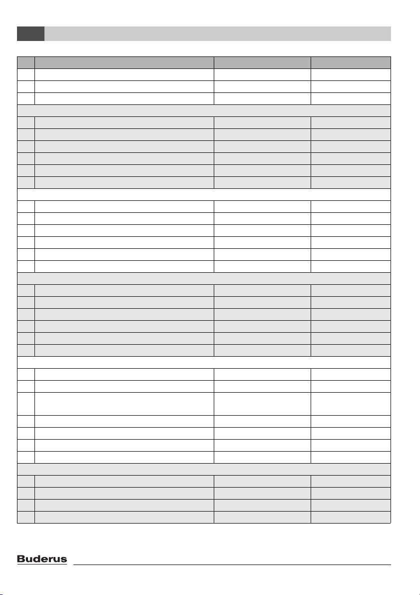
• Provision of the SNVT data for systems consisting of:
Communication objects Variant 2 boiler Variant 4 boiler
Boiler 2 4
Heating zones 5 1
DHW zone with tank charging pump and
11
recirculation pump
Solar thermal system for DHW heating 1 -
Tab. 3 Variants
2.4 Specifications
Unit Logamatic LON-Gateway
Power supply L 6 V AC, 400 mA
Frequency Hz 50/60 Hz
Power consumption VA 1.5
Dimensions (width/height/depth) inches (mm) 5-1/8" / 5-1/2" / 9/16"
(130/140/40)
Weight oz (g) 14 (400)
Operating temperature °F (°C) 40 to 122 (5 to 50)
Protection level IP40
Tab. 4 Specifications
2.5 Specified communication objects
With the LON-Gateway, selected data from up to four Logamatic 4000 control panels can be
exchanged via LON data bus with third-party control systems.
In addition to the communication objects for the first boilers, which are a component of the control
panel, additional functions in the form of modules for multi-boiler systems, heating zones, DHW, and
solar can be added.
If heating zones are served via LON, no other remote controls, e.g. Buderus remote
control BFU, may be connected to this heating zone.
8
Technical Information Logamatic LON-Gateway - Subject to modifications resulting from technical improvements!
Product description
2
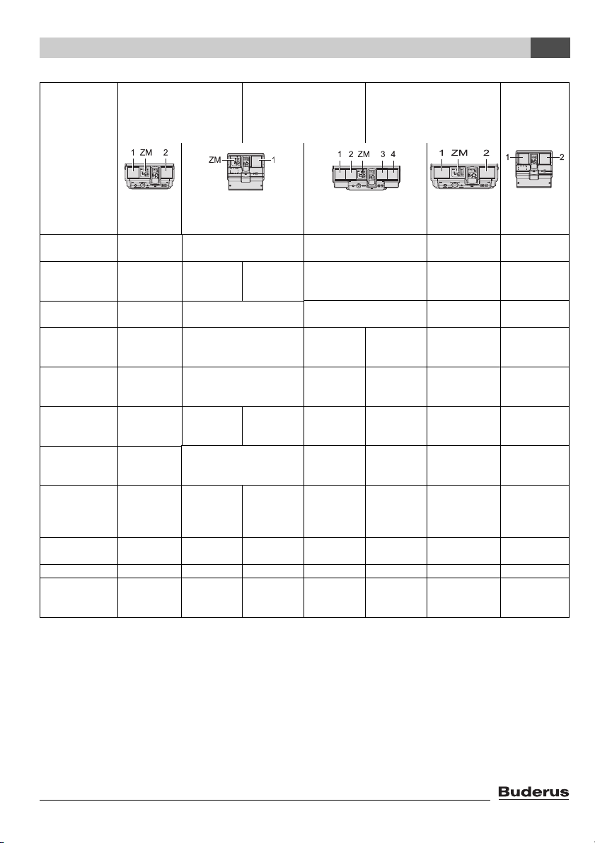
Requirement
5 heating zones
Logamatic
4211
Boiler with
Logamatic 4000y(ZM422)
Boiler with
– y
Logamatic EMS
1 boiler
1 DHW
1 solar
Logamatic
4121
–o
(ZM424)o(FM456 in
2 boiler
5 heating zones
1 DHW
1 solar
Logamatic
4321
2)
(FM458)
2)
o
(FM458)
4 boilers
1 heating zone
1 DHW
Logamatic
4323
(FM458)
(FM458)
Expansion
for heating
zones 3, 4
Logamatic
4122
2)
o
2)
o
–
–
slot 2)
DHW heating y
(ZM422)
LON HK 1 o
(FM442 in
slot 1)
LON HK 2 o
(FM442 in
slot 1)
LON HK 5 y
(ZM422)
y
(ZM424)
y
(ZM424)
(FM442 in
o
(FM441 in slot 2)o(FM441 in slot 1)
o
(FM441 in
slot 1)
y
(ZM424)
o
(FM442 in
slot 1)
––o
(FM442 in
–
o
o
–
(FM441 in slot 1)
slot 1)
–– –
–– –
slot 3)
Solar DHW
heating
LON HK 3
LON HK 4
o
(FM443 in
slot 2)
1)
o
o
(FM443 in slot 2)
1)
o
o
o
(FM443 in
1)
slot 2)
o
(4322 with
FM442 in
–– –
–– o
(FM442 in
slot 2)
slot 2)
LON flasher
version
XIF file version LON_2B_00 LON_2B_00 LON_2B_00 LON_2B_00 LON_4B_00 LON_4B_00
Address of
LON Flasher
2B_00
LON Flasher
2B_E_00
LON Flasher
2B_E_00
LON Flasher
2B_00
1111
3)
LON Flasher
4B_00
3)
1
LON Flasher
4B_00
12
Logamatic
control panel
Tab. 5 Overview of LON-Gateway and Logamatic control system
1) Logamatic 4122 required if LON heating zones 3 and 4 are required in one and two-boiler systems.
2) Function module FM458 combines boiler with the Logamatic 4000 and Logamatic EMS control system.
3) ECOCAN-BUS address of the Logamatic 4321 control panel on the first boiler; additional boilers with
Logamatic 4321 control panel of the 4322 are assigned ECOCAN-BUS addresses 2 to 4.
1)
y = Basic equipment
o = Optional (required accessories in parentheses)
– = Not required
Technical Information Logamatic LON-Gateway - Subject to modifications resulting from technical improvements!
9
Product description
2
2.6 Logamatic LON-Gateway firmware
2.6.1 Firmware when delivered
When delivered, the firmware version LON_Flasher_2B_00 is preinstalled. This version is for a
heating system with floor-standing boilers with Logamatic 4321. If you need another firmware variant
(e.g. LON_Flasher_4B_00) for your installation, it is easy to update the firmware. (see procedure for
updating firmware)
The firmware version of your LON-Gateway is displayed via the Logamatic ECO-SOFT
4000/EMS service software (Start communication -> Select COM port settings ->
Direct connection).
You can find the correct COM port under: Windows XP from the device manager
(Control panel -> System -> Hardware -> Device manager -> COM port).
Procedure for Windows Visa and Windows 7: Control panel -> Hardware and Sound > Device manager -> COM port.
2.6.2 Procedure for updating firmware
First the LON-Gateway must be connected to the power supply and connected on-site to your
computer via the RS232 interface or USB converter.
B Obtain the desired firmware from Buderus and, start the LONFlasher*******.exe.
B Select the COM port.
B Start the update with the Flash button.
A display informs you about the current progress. The update is only complete when a message
"...successful!" appears.
B When a message "...successful!" appears, confirm with OK.
The update is complete.
After the successful update, disconnect the LON-Gateway from the line voltage for approx.
2 minutes to perform a reset. This completes the firmware update.
10
Technical Information Logamatic LON-Gateway - Subject to modifications resulting from technical improvements!
Network interface
3
3 Network interface
3.1 Overview of the SNVTs for variant 2 boilers
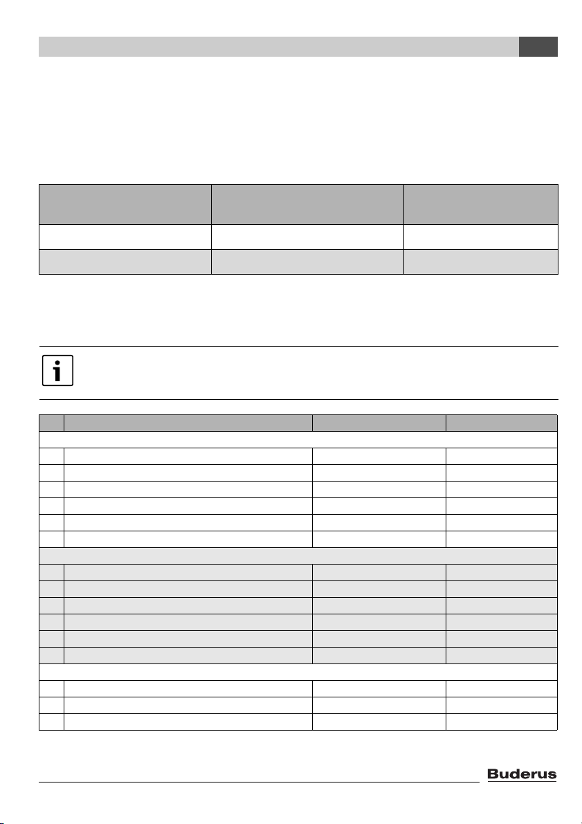
The prerequisite for the proper function is that the firmware on the LON-Gateway interface has at
least the version number indicated below and the following application file is used:
Buderus
Alternative
2 boilers with Logamatic EMS LON_Flasher_2B_E_00 LON_2B_00
2 boilers with Logamatic 4000 LON_Flasher_2B_00 LON_2B_00
(alternative of the LON-Flasher)
LON application file
(XIF file)
Tab. 6
Communication via the Logamatic LON-Gateway takes place using standard network variable types
(SNVT). Standard configuration parameter types (SCPTs) are not used.
Set the system up for repeated reading of SNVTs, which ensure data exchange
between the network participants.
No. Meaning SNVT type SNVT name
General
0 Time SNVT_time_ stamp(84) nviUhrzeit
1 Outdoor temperature SNVT_temp_p(105) nvoAussen_Tp
2 Error message 1 control unit addresses 1 + 2 SNVT_state(83) nvoFehler1
3 Error message 2 control unit addresses 1 + 2 SNVT_state(83) nvoFehler2
4 Error message 3 control unit addresses 1 + 2 SNVT_state(83) nvoFehler3
5 Error message 4 control unit addresses 1 + 2 SNVT_state(83) nvoFehler4
Heating zone 1
6 Change operating mode (D/N/A) SNVT_hvac_mode(108) nviHK1TgNtAt
7 Change room set point night temperature SNVT_temp_p(105) nviHK1RaumSNt_Tp
8 Change room set point day temperature SNVT_temp_p(105) nviHK1RaumSTg_Tp
9 Display room set point temperature SNVT_temp_p(105) nvoHK1Raum_S_Tp
10 Display operating mode (D/N/A) SNVT_hvac_mode(108) nvoHK1Betrieb
11 Display heating zone supply actual temperature SNVT_temp_p(105) nvoHK1VLIst_Tp
Heating zone 2
12 Change operating mode (D/N/A) SNVT_hvac_mode(108) nviHK2TgNtAt
13 Change room set point night temperature SNVT_temp_p(105) nviHK2RaumSNt_Tp
14 Change room set point day temperature SNVT_temp_p(105) nviHK2RaumSTg_Tp
Tab. 7 Service menu navigator
Technical Information Logamatic LON-Gateway - Subject to modifications resulting from technical improvements!
11
Network interface
3
No. Meaning SNVT type SNVT name
15 Display room set point temperature SNVT_temp_p(105) nvoHK2Raum_S_Tp
16 Display operating mode (D/N/A) SNVT_hvac_mode(108) nvoHK2Betrieb
17 Display heating zone supply actual temperature SNVT_temp_p(105) nvoHK2VLIst_Tp
Heating zone 3
18 Change operating mode (D/N/A) SNVT_hvac_mode(108) nviHK3TgNtAt
19 Change room set point night temperature SNVT_temp_p(105) nviHK3RaumSNt_Tp
20 Change room set point day temperature SNVT_temp_p(105) nviHK3RaumSTg_Tp
21 Display room set point temperature SNVT_temp_p(105) nvoHK3Raum_S_Tp
22 Display operating mode (D/N/A) SNVT_hvac_mode(108) nvoHK3Betrieb
23 Display heating zone supply actual temperature SNVT_temp_p(105) nvoHK3VLIst_Tp
Heating zone 4
24 Change operating mode (D/N/A) SNVT_hvac_mode(108) nviHK4TgNtAt
25 Change room set point night temperature SNVT_temp_p(105) nviHK4RaumSNt_Tp
26 Change room set point day temperature SNVT_temp_p(105) nviHK4RaumSTg_Tp
27 Display room set point temperature SNVT_temp_p(105) nvoHK4Raum_S_Tp
28 Display operating mode (D/N/A) SNVT_hvac_mode (108) nvoHK4Betrieb
29 Display heating zone supply actual temperature SNVT_temp_p(105) nvoHK4VLIst_Tp
Heating zone 5
30 Change operating mode (D/N/A) SNVT_hvac_mode (108) nviHK5TgNtAt
31 Change room set point night temperature SNVT_temp_p(105) nviHK5RaumSNt_Tp
32 Change room set point day temperature SNVT_temp_p(105) nviHK5RaumSTg_Tp
33 Display room set point temperature SNVT_temp_p(105) nvoHK5Raum_S_Tp
34 Display operating mode (D/N/A) SNVT_hvac_mode (108) nvoHK5Betrieb
35 Display heating zone supply actual temperature SNVT_temp_p(105) nvoHK5VLIst_Tp
DHW
36 Change operating mode (D/N/A) SNVT_hvac_mode (108) nviHK1TgNtAt
37 Change DHW set point temperature SNVT_temp_p(105) nviWW_Set_Tp
38 Change recirculation pump operating mode
SNVT_hvac_mode (108) nviZP_TgNtAt
(D/N/A)
39 Display operating mode (D/N/A) SNVT_hvac_mode (108) nvoWW_Betrieb
40 Display DHW set point temperature SNVT_temp_p(105) nvoWW_S_Tp
41 Display DHW actual temperature SNVT_temp_p(105) nvoWW_Ist_Tp
42 Display recirculation pump operating mode (D/N/A) SNVT_hvac_mode (108) nvoZP_Betrieb
Strategy
43 Change system operating mode (D/N/A) SNVT_hvac_mode (108) nviAnlTgNtAt
44 Change system supply set point temperature SNVT_temp_p(105) nviAnlVorgabe_Tp
45 Display system supply actual temperature SNVT_temp_p(105) nvoAnlVLIst_Tp
46 Display system return actual temperature SNVT_temp_p(105) nvoAnlRLIst_Tp
Tab. 7 Service menu navigator
12
Technical Information Logamatic LON-Gateway - Subject to modifications resulting from technical improvements!
Network interface
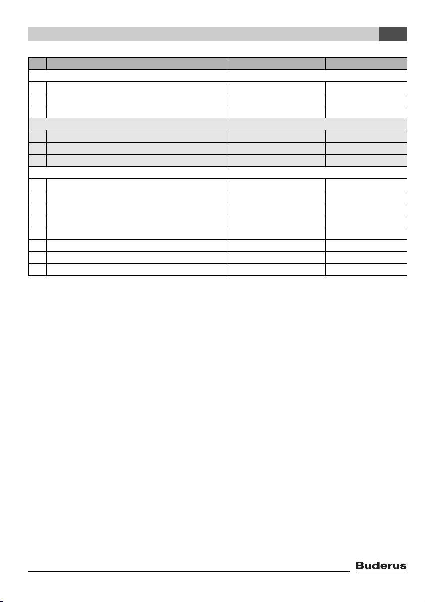
No. Meaning SNVT type SNVT name
Boiler 1
47 Status of burner boiler 1
1)
SNVT_state(83) nvoKS1Br1Stufe1
48 Status burner boiler 1 SNVT_state(83) nvoKS1Br1Stufe2
49 Display boiler actual temperature SNVT_temp_p(105) nvoKS1VLIst_Tp
Boiler 2
50 Status burner boiler 2
1)
SNVT_state(83) nvoKS2Br1Stufe1
51 Status burner boiler 2 SNVT_state(83) nvoKS2Br1Stufe2
52 Display boiler actual temperature SNVT_temp_p(105) nvoKS2VLIst_Tp
Solar thermal system
53 Change operating mode (D/N/A) SNVT_hvac_mode (108) nviSLTgNtAt
54 Display operating mode (D/N/A) SNVT_hvac_mode (108) nvoSLBetrieb
55 Display collector actual temperature (FSK) SNVT_temp_p(105) nvoSLKoll_Tp
56 Display solar tank actual temperature (FSS1) SNVT_temp_p(105) nvoSLSP1Unten_Tp
57 Display solar yield (heat quantity) SNVT_elec_kwh_l (146) nvoSLWMZ_Ertrag
58 SNVT_file_pos(90) nviParameter
59 SNVT_file_pos(90) nviAdresse
60 SNVT_file_pos(90) nvoMonitoring
Tab. 7 Service menu navigator
1) Display of the output for boilers with Logamatic EMS
3
Technical Information Logamatic LON-Gateway - Subject to modifications resulting from technical improvements!
13
Network interface
3
3.2 Description of the SNVTs for variant 2 boilers
Note:
The right column indicates the number of bytes.
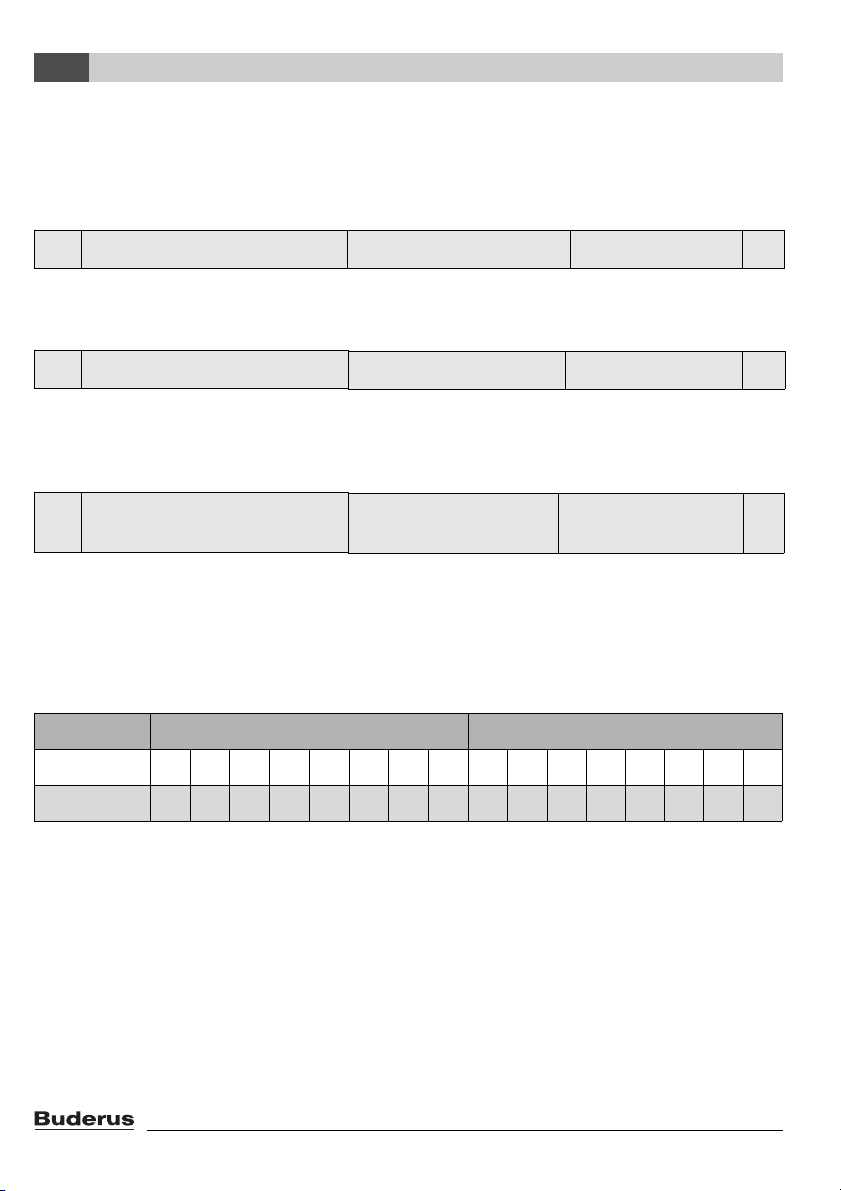
3.2.1 General
0 Time SNVT_time_ stamp(84) nviUhrzeit 7
Tab. 8 Value for comparison of the time in the Buderus control system with the LON network
Format: YYYY/MM/DD hh:mm:ss
1 Outdoor temperature SNVT_temp_p(105) nvoAussen_Tp 2
Tab. 9 Display of the current outdoor temperature
Note:
230 °F (110 °C) is an invalid value (e.g. no temperature sensor connected, sensor defective, etc.)
2 Error message 1 control
SNVT_state(83) nvoFehler1 2
panel address 1 + 2
Tab. 10 Output for error messages: error 1 of control panel 1 and 2
For the error list, see Chapter 7, page 43.
Error messages are displayed as 2-byte values (2 x 8 bits). The first byte (the first 8 bits seen from
the left) is the interpretation of the error message of control panel address 2. The second byte (the
remaining 8 bits) is the interpretation of the error message of control panel address 1:
First byte - error boiler 2 Second byte - error boiler 1
Display 0000000000000000
Interpretation 2021222324252627202122232425262
7
Tab. 11
Errors are displayed as binary values and must be converted to decimal values. By comparing with
the error list (see Chapter 7, page 43), the associated texts are assigned to the error numbers.
Example: see page 27
14
Technical Information Logamatic LON-Gateway - Subject to modifications resulting from technical improvements!
Network interface
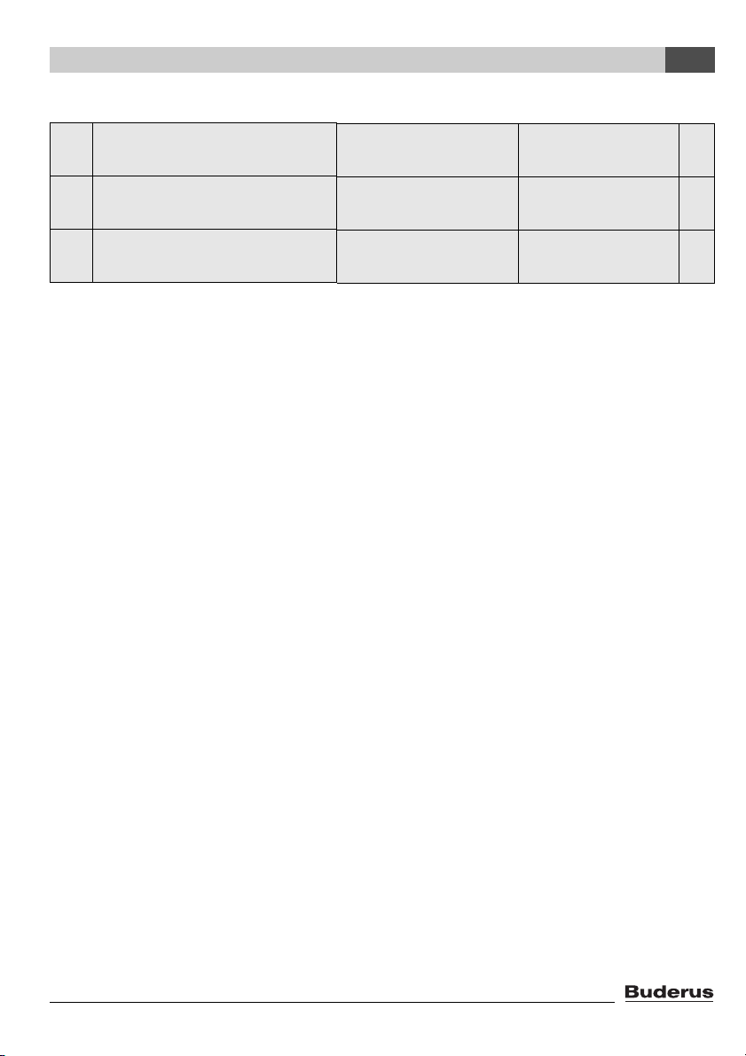
Example:
3
3 Error message 2 control
SNVT_state(83) nvoFehler1 2
panel address 1 + 2
4 Error message 3 control
SNVT_state(83) nvoFehler1 2
panel address 1 + 2
5 Error message 4 control
SNVT_state(83) nvoFehler1 2
panel address 1 + 2
Tab. 12 Outputs for error messages
Second, third, and fourth current errors in the control panel in question. List of the error list, see
Chapter 7, page 43.
Interpretation as described for error message 1.
Technical Information Logamatic LON-Gateway - Subject to modifications resulting from technical improvements!
15
 Loading...