

Page 1
Mounting and Service
Instructions
Room controller
Logamatic EMS
RC35 user interface
6 720 618 477-00.1RS
For trained and
certified installers
Read carefully prior
to installation and
maintenance.
6 720 640 227 - 05/2009 US/CA
Page 2

Contents
Contents
1 Explanation of symbols and safety instructions . . . . . . . . . . . . . . . . . . . . . . . . . . . . . . . 4
1.1 Explanation of symbols . . . . . . . . . . . . . . . . . . . . . . . . . . . . . . . . . . . . . . . . . . . . . . . . . . . . . 4
1.2 Safety instructions . . . . . . . . . . . . . . . . . . . . . . . . . . . . . . . . . . . . . . . . . . . . . . . . . . . . . . . . 6
2 Product description . . . . . . . . . . . . . . . . . . . . . . . . . . . . . . . . . . . . . . . . . . . . . . . . . . . . . . . . 7
2.1 Correct use . . . . . . . . . . . . . . . . . . . . . . . . . . . . . . . . . . . . . . . . . . . . . . . . . . . . . . . . . . . . . . 7
2.2 Certifications . . . . . . . . . . . . . . . . . . . . . . . . . . . . . . . . . . . . . . . . . . . . . . . . . . . . . . . . . . . . . 7
2.3 Package contents . . . . . . . . . . . . . . . . . . . . . . . . . . . . . . . . . . . . . . . . . . . . . . . . . . . . . . . . . 7
2.4 Technical specifications . . . . . . . . . . . . . . . . . . . . . . . . . . . . . . . . . . . . . . . . . . . . . . . . . . . . 8
2.5 Applicability of these instructions for function modules (accessories) . . . . . . . . . . . . . . 9
2.6 Accessories . . . . . . . . . . . . . . . . . . . . . . . . . . . . . . . . . . . . . . . . . . . . . . . . . . . . . . . . . . . . . . 9
3 Installation . . . . . . . . . . . . . . . . . . . . . . . . . . . . . . . . . . . . . . . . . . . . . . . . . . . . . . . . . . . . . . . 10
3.1 Choosing the right installation location . . . . . . . . . . . . . . . . . . . . . . . . . . . . . . . . . . . . . . 10
3.1.1 Installation in reference room . . . . . . . . . . . . . . . . . . . . . . . . . . . . . . . . . . . . . . . . . . . . . . 10
3.1.2 Installation on boiler . . . . . . . . . . . . . . . . . . . . . . . . . . . . . . . . . . . . . . . . . . . . . . . . . . . . . . 11
3.2 Types of installation . . . . . . . . . . . . . . . . . . . . . . . . . . . . . . . . . . . . . . . . . . . . . . . . . . . . . . 11
3.3 Installation and connection . . . . . . . . . . . . . . . . . . . . . . . . . . . . . . . . . . . . . . . . . . . . . . . . 12
3.4 User interface: attaching or removing . . . . . . . . . . . . . . . . . . . . . . . . . . . . . . . . . . . . . . . . 13
4 Operating basics . . . . . . . . . . . . . . . . . . . . . . . . . . . . . . . . . . . . . . . . . . . . . . . . . . . . . . . . . . 14
4.1 Overview of operation . . . . . . . . . . . . . . . . . . . . . . . . . . . . . . . . . . . . . . . . . . . . . . . . . . . . 14
4.2 Introduction to the Service menu . . . . . . . . . . . . . . . . . . . . . . . . . . . . . . . . . . . . . . . . . . . 15
4.3 Overview of the Service menu . . . . . . . . . . . . . . . . . . . . . . . . . . . . . . . . . . . . . . . . . . . . . . 17
5 Commissioning . . . . . . . . . . . . . . . . . . . . . . . . . . . . . . . . . . . . . . . . . . . . . . . . . . . . . . . . . . . 18
5.1 General commissioning . . . . . . . . . . . . . . . . . . . . . . . . . . . . . . . . . . . . . . . . . . . . . . . . . . . 18
5.2 Checklist: important parameters for commissioning . . . . . . . . . . . . . . . . . . . . . . . . . . . . 19
5.3 Quick commissioning (Quick operation menu) . . . . . . . . . . . . . . . . . . . . . . . . . . . . . . . . 20
5.4 Detailed commissioning . . . . . . . . . . . . . . . . . . . . . . . . . . . . . . . . . . . . . . . . . . . . . . . . . . . 21
5.5 System commissioning . . . . . . . . . . . . . . . . . . . . . . . . . . . . . . . . . . . . . . . . . . . . . . . . . . . 21
5.6 Shut-down/switching off . . . . . . . . . . . . . . . . . . . . . . . . . . . . . . . . . . . . . . . . . . . . . . . . . . 22
5.7 Operating tips . . . . . . . . . . . . . . . . . . . . . . . . . . . . . . . . . . . . . . . . . . . . . . . . . . . . . . . . . . . 23
Logamatic EMS RC35 user interface - Subject to technical modifications.2
Page 3

Contents
6 Entering system settings (Service menu – Settings) . . . . . . . . . . . . . . . . . . . . . . . . . . 24
6.1 System data . . . . . . . . . . . . . . . . . . . . . . . . . . . . . . . . . . . . . . . . . . . . . . . . . . . . . . . . . . . . . 24
6.1.1 Type of building (“damping” of outdoor temperature) . . . . . . . . . . . . . . . . . . . . . . . . . . . 25
6.1.2 Minimum outdoor temperature . . . . . . . . . . . . . . . . . . . . . . . . . . . . . . . . . . . . . . . . . . . . . . 26
6.2 Boiler data . . . . . . . . . . . . . . . . . . . . . . . . . . . . . . . . . . . . . . . . . . . . . . . . . . . . . . . . . . . . . . 27
6.3 Heating zone data . . . . . . . . . . . . . . . . . . . . . . . . . . . . . . . . . . . . . . . . . . . . . . . . . . . . . . . 28
6.3.1 Assignment of user interface/remote control unit in the software . . . . . . . . . . . . . . . . . . 32
6.3.2 Control mode (outdoor temperature controlled/room influence) . . . . . . . . . . . . . . . . . . 32
6.3.3 Characteristic heating curve . . . . . . . . . . . . . . . . . . . . . . . . . . . . . . . . . . . . . . . . . . . . . . . .33
6.3.4 Reduction modes (night setback) . . . . . . . . . . . . . . . . . . . . . . . . . . . . . . . . . . . . . . . . . . . 34
6.3.5 Frost protection . . . . . . . . . . . . . . . . . . . . . . . . . . . . . . . . . . . . . . . . . . . . . . . . . . . . . . . . . . 35
6.4 Domestic hot water (DHW) . . . . . . . . . . . . . . . . . . . . . . . . . . . . . . . . . . . . . . . . . . . . . . . . 37
6.5 Solar data . . . . . . . . . . . . . . . . . . . . . . . . . . . . . . . . . . . . . . . . . . . . . . . . . . . . . . . . . . . . . . . 39
6.6 RC35 calibration . . . . . . . . . . . . . . . . . . . . . . . . . . . . . . . . . . . . . . . . . . . . . . . . . . . . . . . . . 40
6.7 Contact data . . . . . . . . . . . . . . . . . . . . . . . . . . . . . . . . . . . . . . . . . . . . . . . . . . . . . . . . . . . . 41
7 Diagnosis . . . . . . . . . . . . . . . . . . . . . . . . . . . . . . . . . . . . . . . . . . . . . . . . . . . . . . . . . . . . . . . . 42
7.1 Function test . . . . . . . . . . . . . . . . . . . . . . . . . . . . . . . . . . . . . . . . . . . . . . . . . . . . . . . . . . . . 42
7.2 Monitor value . . . . . . . . . . . . . . . . . . . . . . . . . . . . . . . . . . . . . . . . . . . . . . . . . . . . . . . . . . . . 43
7.3 Error message . . . . . . . . . . . . . . . . . . . . . . . . . . . . . . . . . . . . . . . . . . . . . . . . . . . . . . . . . . . 44
7.4 Characteristic heating curve . . . . . . . . . . . . . . . . . . . . . . . . . . . . . . . . . . . . . . . . . . . . . . . . 45
7.5 Versions . . . . . . . . . . . . . . . . . . . . . . . . . . . . . . . . . . . . . . . . . . . . . . . . . . . . . . . . . . . . . . . . 45
8 Service . . . . . . . . . . . . . . . . . . . . . . . . . . . . . . . . . . . . . . . . . . . . . . . . . . . . . . . . . . . . . . . . . . 46
9 Reset . . . . . . . . . . . . . . . . . . . . . . . . . . . . . . . . . . . . . . . . . . . . . . . . . . . . . . . . . . . . . . . . . . . . 47
10 Troubleshooting . . . . . . . . . . . . . . . . . . . . . . . . . . . . . . . . . . . . . . . . . . . . . . . . . . . . . . . . . . 48
11 Service menu RC35 . . . . . . . . . . . . . . . . . . . . . . . . . . . . . . . . . . . . . . . . . . . . . . . . . . . . . . . 54
Index . . . . . . . . . . . . . . . . . . . . . . . . . . . . . . . . . . . . . . . . . . . . . . . . . . . . . . . . . . . . . . . . . . . . 55
Notes . . . . . . . . . . . . . . . . . . . . . . . . . . . . . . . . . . . . . . . . . . . . . . . . . . . . . . . . . . . . . . . . . . . . 57
Logamatic EMS RC35 user interface - Subject to technical modifications. 3
Page 4
1
Explanation of symbols and safety instructions
1 Explanation of symbols and safety instructions
1.1 Explanation of symbols
Warnings
Warnings in the text are indicated by a warning triangle with a gray background in a
framed box.
In case of danger due to current, the exclamation point on the warning triangle is
replaced with a lightning symbol.
Signal words at the beginning of a warning are used to indicate the type and seriousness of the
ensuing risk if measures for minimizing damage are not taken.
• NOTE indicates that damage to property may occur.
• CAUTION indicates possible minor to medium personal injury.
• WARNING indicates possible severe personal injury.
• DANGER indicates that severe personal injury may occur.
Important Information
Important information that presents no risk to people or property is indicated with this
symbol. They are separated by lines above and below the text.
Additional symbols
Symbol Explanation
B Sequence of steps
Æ Cross-reference to other points in this document or to other documents
• Listing/list entry
– Listing/list entry (2nd level)
Tab. 1
Logamatic EMS RC35 user interface - Subject to technical modifications.4
Page 5
Explanation of symbols and safety instructions
1
Display text: Words appearing on the display are shown in bold
in the text.
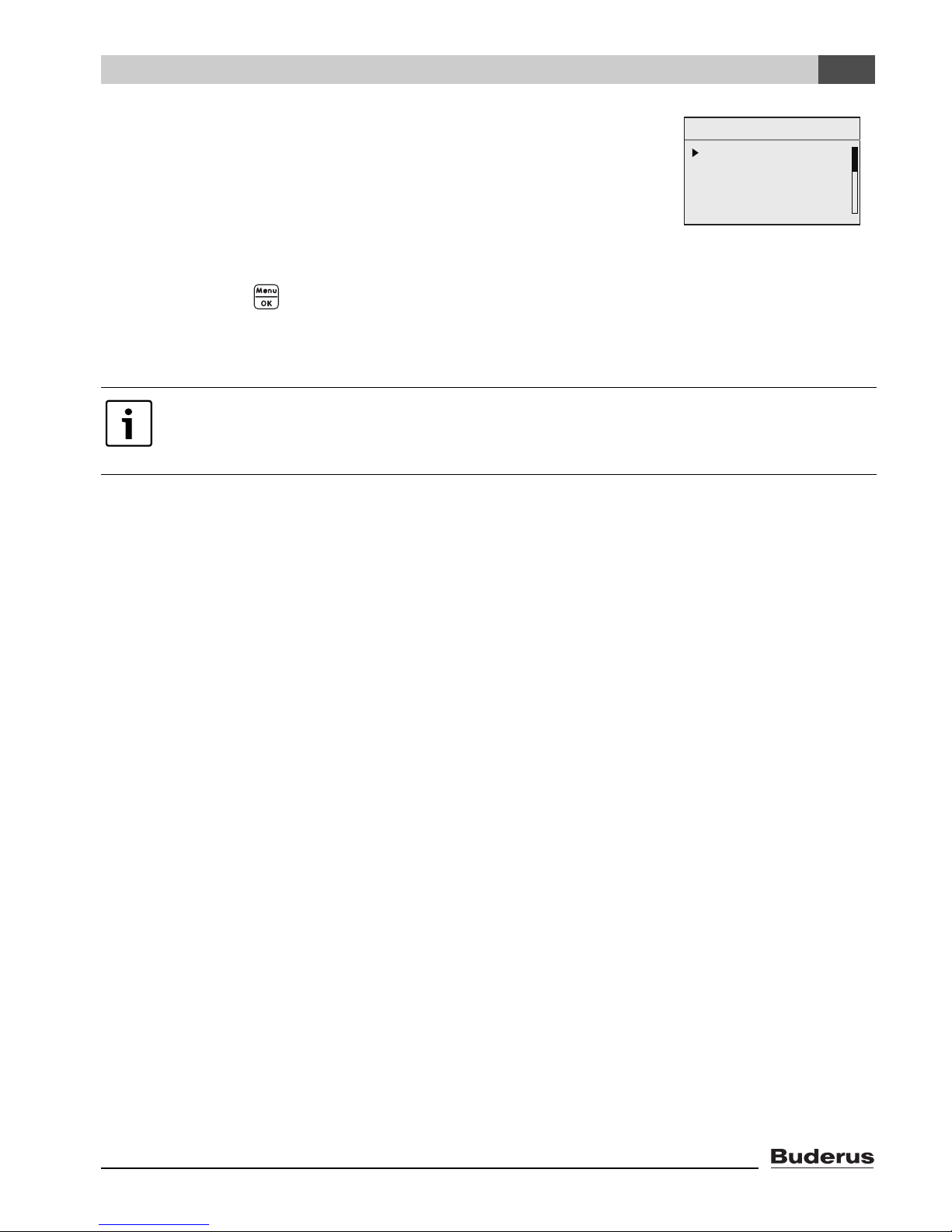
Example: USER MENU
USER MENU
standard display
modes of operation
program
WWSD temperature
Action sequences: Sequences of steps are marked with a triangle with its point towards the text.
Example: Press .
If action sequences have more than two steps and the order of the steps is important,
they are numbered (1., 2., ...).
Note on using this manual: Section 4.2 "Introduction to the Service menu" explains
in detail the steps needed for programming all the settings in the Service menu. In the
sections which come after it, programming is only exexplained in outline.
Logamatic EMS RC35 user interface - Subject to technical modifications. 5
Page 6

1
Explanation of symbols and safety instructions
1.2 Safety instructions
Installation and commissioning
B Observe all instructions to ensure satisfactory operation.
B Read and observe the safety information and codes of conduct.
B Installation and commissioning must only be carried out by qualified and trained system installers.
Use
B Always use this device correctly and in conjunction with the stated control systems.
B Observe all regulations, standards, and codes applicable to installation and operation of the
system in your country.
Risk of death from electric shock
B The electrical supply must be connected by a qualified electrician. The terminal diagram must be
followed.
B Before installation: isolate all poles of the power supply (120 V AC).
B Do not install this device in rooms with high moisture exposure (e.g. bathrooms, saunas).
B Never directly connect this device to the 120 V AC power mains.
Risk of scalding at the taps
B Make sure that a thermostatic mixing valve is installed and that it is set to temperatures below
122 °F (50 °C).
Warning: frost
The heating system can freeze up in cold weather, if switched OFF or locked out.
B Leave the heating system permanently switched ON.
B Enable frost protection.
B In the event of a fault: remedy the fault immediately.
Warning: device damage
The RC35 has no field serviceable parts inside. Attempt to open the housing will cause internal
damage, render the device inoperable, and void the manufacturer's warranty.
B In case of system irregularities please consult the 7 "Diagnosis" and 10 "Troubleshooting"
sections of this manual.
Logamatic EMS RC35 user interface - Subject to technical modifications.6
Page 7
Product description
2
2 Product description
2.1 Correct use
The RC35 control unit is intended for the operation and control of Buderus heating systems in single
and multi-family houses.
The boiler must be equipped with EMS (energy management system).
The user interface must not be used in conjunction with Logamatic 2000/4000 control units.
We recommend that the heating system is always operated with a user interface (only emergency
operation is possible without a user interface).
These instructions describe all the possible functions of the RC35. Some of these functions may
not be available, depending on which boiler (burner control unit) is used. For more information, refer
to the relevant chapter.
For information on the burner control units used, refer to the DIAGNOSIS\VERSIONS menu
(Æ page 45).
2.2 Certifications
This product has been tested and is certified for both the US and Canadian markets,
and meets all applicable US and Canadian standards.
2.3 Package contents
• RC35 user interface
• Operating instructions
• Mounting and maintenance instructions
• Wall bracket, attachment kit
Logamatic EMS RC35 user interface - Subject to technical modifications. 7
Page 8
2
Product description
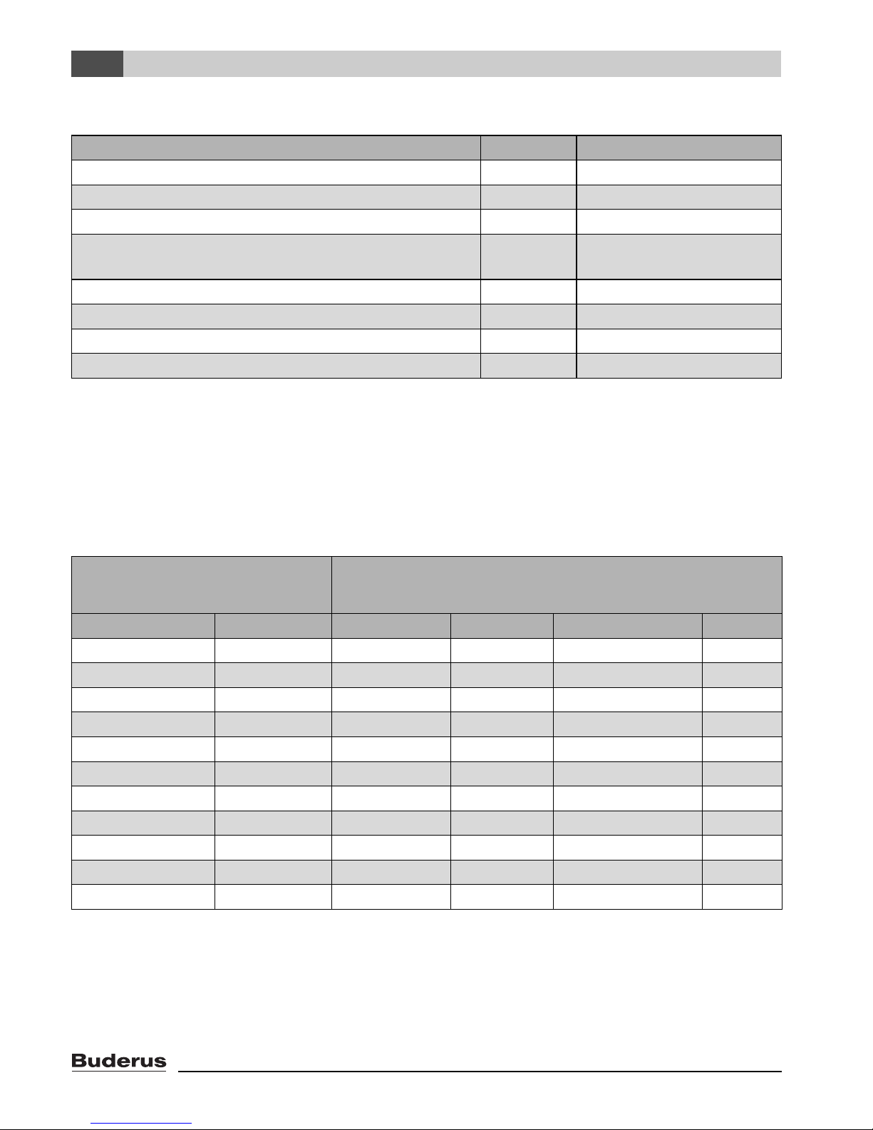
2.4 Technical specifications
Unit RC35
Power supply via bus system V 16 V DC
Power consumption W 0.3
Power consumption with backlight W 0.6
Dimensions (width/height/depth) inches
(mm)
6"/3-1/2"/1-1/2"
(150/90/32)
Weight ounces (g) 8.2 (233)
Operating temperature °F (°C) 32 – 122 (0 – 50)
Storage temperature °F (°C) 32 – 158 (0 – 70)
Relative humidity % 0– 90
Tab. 2 Specifications for the RC35 user interface
Temperature sensor characteristics
When measuring the resistance of temperature sensors, observe the following requirements:
• Isolate from the system before measuring.
• Measure the resistance at the cable ends.
• The resistances represent mean values and are subject to tolerances.
Supply temperature sensor
Outdoor temperature sensor
DHW temperature sensor
°F (°C) k Ω °C k Ω °C k Ω
–4 °F (–20 °C) 96.358 50 °F (10 °C) 19.872 140 °F (60 °C) 2.490
5°F(–15°C) 72.510 59 °F (15 °C) 15.699 149 °F (65 °C) 2.084
14 °F (–10 °C) 55.054 68 °F (20 °C) 12.488 158 °F (70 °C) 1.753
23 °F (–5 °C) 42.162 77 °F (25 °C) 10.001 167 °F (75 °C) 1.481
32 °F (0 °C) 32.556 86 °F (30 °C) 8.060 176 °F (80 °C) 1.256
41 °F (5 °C) 25.339 95 °F (35 °C) 6.535 185 °F (85 °C) 1.070
50 °F (10 °C) 19.872 104 °F (40 °C) 5.331 194 °F (90 °C) 0.915
59 °F (15 °C) 15.699 113 °F (45 °C) 4.372 203 °F (95 °C) 0.786
68 °F (20 °C) 12.488 122 °F (50 °C) 3.606 212 °F (100 °C) 0.677
77 °F (25 °C) 10.001 131 °F (55 °C) 2.989
86 °F (30 °C) 8.060
Tab. 3 Resistances of the 10 kΩ temperature sensors, for EMS only
Logamatic EMS RC35 user interface - Subject to technical modifications.8
Page 9

Product description
2
2.5 Applicability of these instructions for function modules
(accessories)
These instructions also apply to the user interface when used in conjunction with the MM10 mixing
module and the WM10 low loss header module.
If the heating system is equipped with other function modules (e.g. SM10 solar module), additional
settings and menus become available. Please see the instructions included with the module for
details.
2.6 Accessories
For detailed information on suitable accessories, refer to the catalogue.
• MM10 mixing module for controlling a 3-way mixing valve
• WM10 low loss header module
• Solar module and other EMS modules
• Outdoor temperature sensor, separate room temperature sensor
Logamatic EMS RC35 user interface - Subject to technical modifications. 9
Page 10
3
Installation
3 Installation
3.1 Choosing the right installation location
3.1.1 Installation in reference room
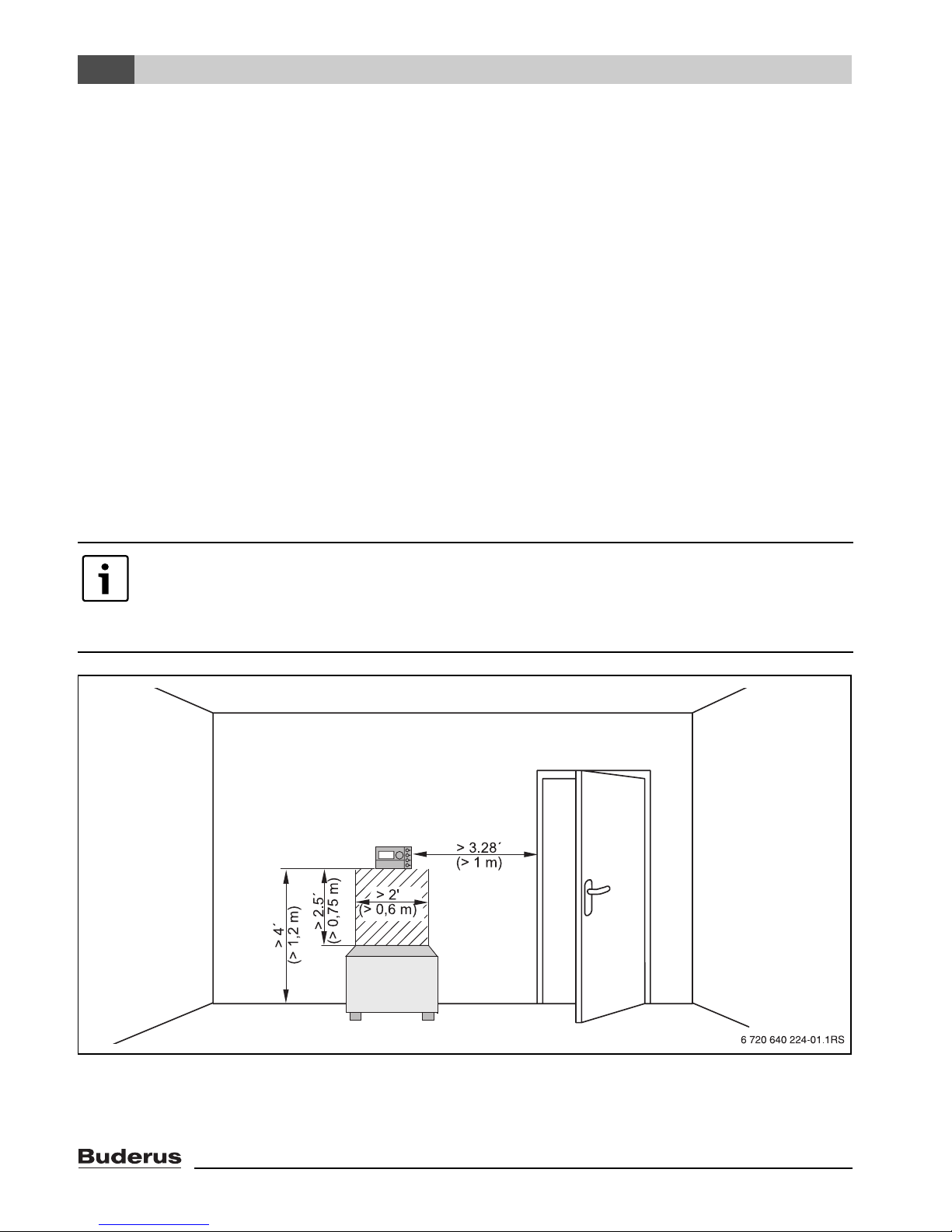
If the system is room-temperature controlled, the following requirements must be met:
• Installation on an internal wall (Æ Fig. 1).
• Maintain the specified distance from door(s) (to avoid drafts).
• Allow clearance below the user interface (Æ Fig. 1, shaded area) (to ensure correct temperature
measurement).
• The reference room (= installation room) must be as representative as possible of the entire home
(or zone) if possible. External heat sources in the reference room (like sunlight or an open
fireplace) affect the control's function. This means it may be too cold in rooms without those
external heat sources.
• The thermostatic valves on the radiators (if installed) in the reference room must always stay fully
open so that the two temperature controls do not affect one another.
If there is no suitable reference room, we recommend setting the system to outdoor
temperature control instead (this requires an outdoor sensor). Alternatively, you could
install an external room temperature sensor in the room with the greatest heating
requirements (e.g. living room).
Fig. 1 Minimum clearances for mounting in a reference room
Logamatic EMS RC35 user interface - Subject to technical modifications.10
Page 11
Installation
3
3.1.2 Installation on boiler
The unit can be installed directly on boilers equipped with EMS.
3.2 Types of installation
The user interface can be installed in three different ways:
• As the only user interface in the system (factory setting): the RC35 user interface is mounted in
a room in the home (the reference room) or on the boiler.
Example: single-family house with one heating zone.
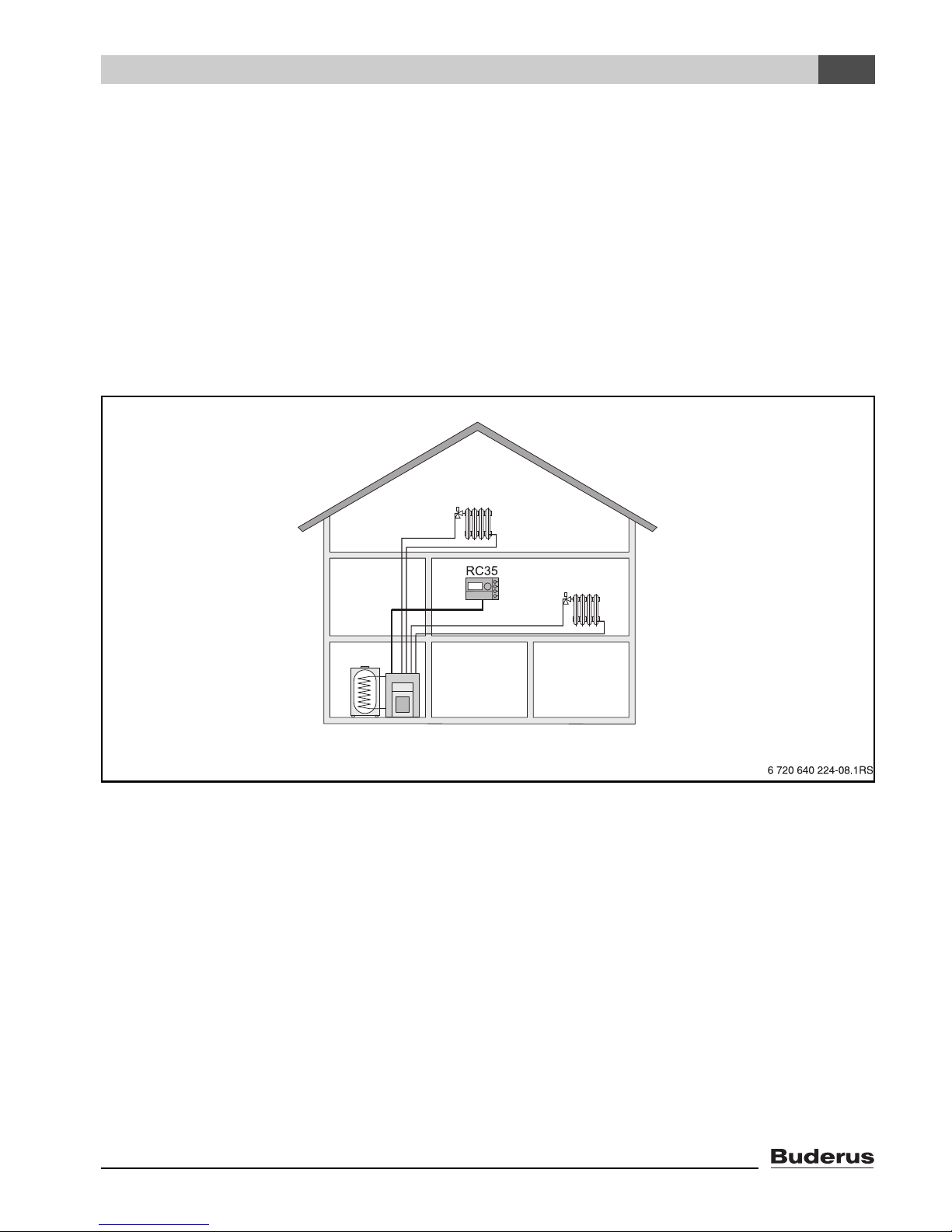
• As the only user interface in a heating system with two or more heating zones (Æ Fig. 2).
Examples: radiant floor heating on one story, radiators in the other.
HZ1
HZ2
Fig. 2 Options for a heating system with two heating zones
Logamatic EMS RC35 user interface - Subject to technical modifications. 11
Page 12
3
Installation
3.3 Installation and connection
Please use only the wall bracket with screw terminals.
B If a wall bracket without screw terminals is already installed, replace it.
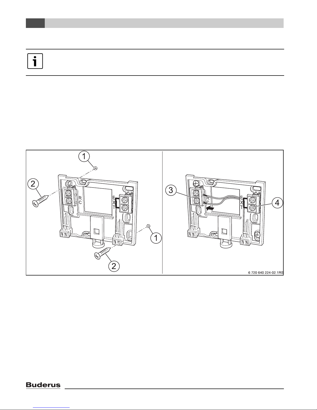
The wall bracket can be attached directly to the wall.
B Mount the wall bracket (Æ Fig. 3, left).
B Connect the two-wire bus cable from the Energy Management System (EMS) to the “RC” cable
terminals (Æ Fig. 3, [3]).
2
– Cable type: AWG18 (8 ft
– The two wires are not polarity sensitive.
– Never route the cables next to power cables.
(0.75 mm2)), length max. 330 ft. (100 m)
Fig. 3 Mounting the wall bracket (left) and connecting the wires (right)
1 Hole drilled in the wall
2 Screws (included with the unit) for surface-mounting on the wall
3 “RC” terminals for EMS (boiler)
4 “EXT” terminals for external room temperature sensor or for jumper
B If the RC35 is operated without an external room sensor, a jumper is needed on the “EXT”
terminals (Æ Fig. 3, [4]) (the jumper is factory-installed).
B If the RC35 is operated with an external room temperature sensor (optional), the factory-installed
jumper on “EXT” must be removed and the external room temperature sensor must be connected
there instead.
Logamatic EMS RC35 user interface - Subject to technical modifications.12
Page 13
Installation
3
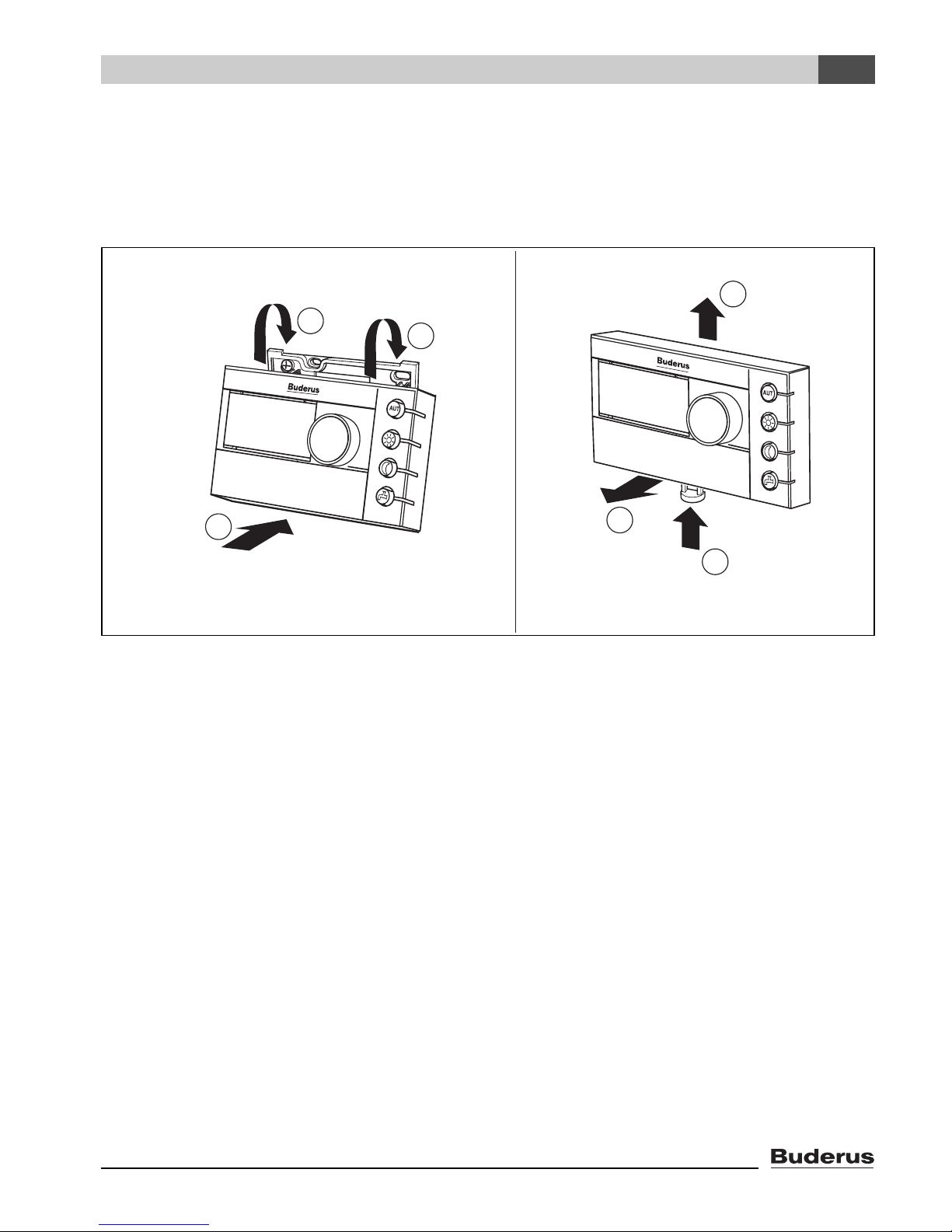
3.4 User interface: attaching or removing
Attaching the user interface
1. Hook the user interface at the top into the mounting plate in the direction of the arrow.
2. Push the user interface at the bottom against the mounting plate, until it snaps into place.
AB
3
1
1
2
2
1
Fig. 4 Attaching the user interface (left) or removing it (right)
Removing the user interface
1. Press the button underneath the mounting plate in the direction of the arrow.
2. At the same time pull the user interface forwards.
3. Remove the user interface by lifting upward.
Logamatic EMS RC35 user interface - Subject to technical modifications. 13
Page 14
4
Operating basics
4 Operating basics
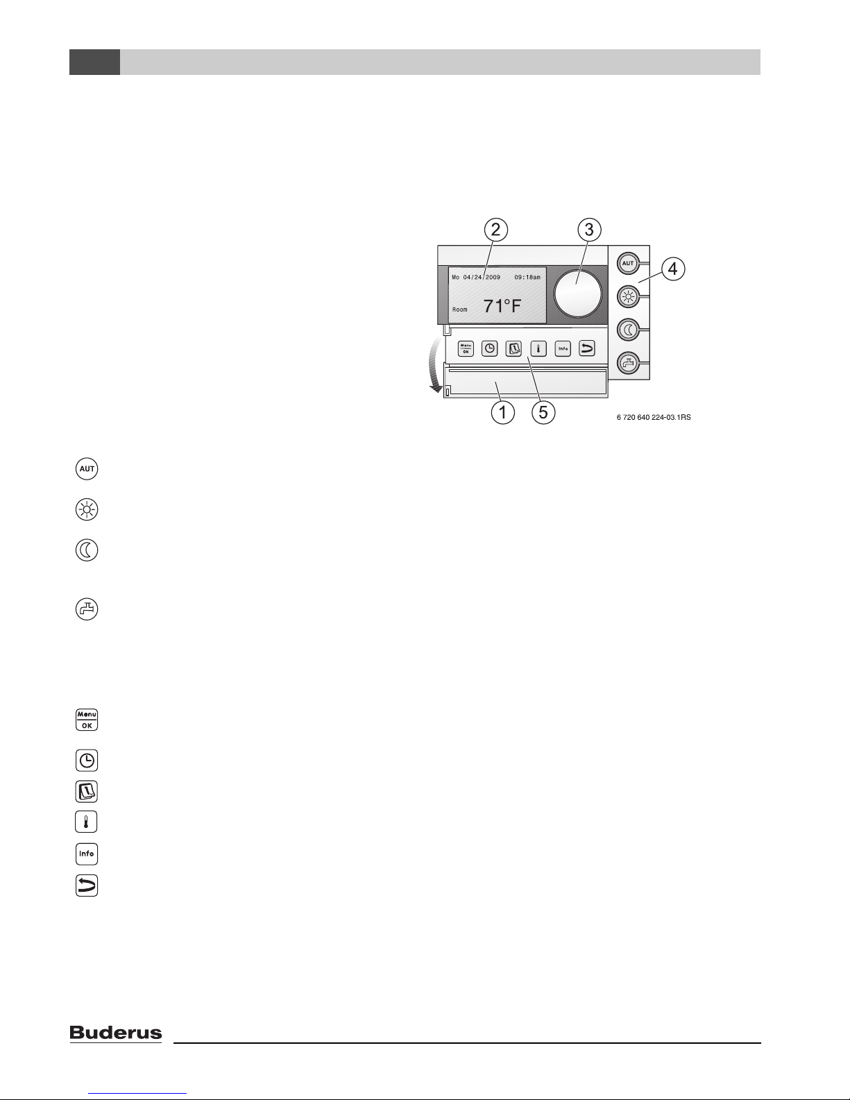
4.1 Overview of operation
Legend for figure:
1 Cover: Pull the recessed grip on the
left to open
2 Display
3 Dial for changing values and
temperatures or for navigating
through the menus
4 Buttons for basic functions: When the LED lights up ...
“AUT” (automatic) • ... the program is active (automatic switchover between day and
night room temperatures).
“Day mode” (manual) • ... the heating system operates at the set day room temperature.
DHW heating is switched on (factory setting).
“Night mode” (manual) • ... the heating system operates at the set night setback room
temperature. Frost protection is active. DHW heating is
switched OFF (factory setting).
“DHW” (domestic hot water) • ... the DHW temperature has fallen below its set value while in
setback mode. The DHW can be heated up again (single
change) by pressing the button (the LED will then flash).
5 Buttons for
additional functions:
“Menu/OK” Open the user menu and confirm the current selection.
“Time” Set the time.
“Date” Set the date.
“Temperature” Set the room temperature.
“Info” Open the Info menu (to view values).
Function:
Turning the dial while pressing the button will change the value.
“Back” Go back one step or one menu item.
In Automatic mode, an additional LED lights up with the “AUT” LED to indicate which operating status is
currently active (“day mode” or “night mode”). The “domestic hot water” LED can also be disabled.
Logamatic EMS RC35 user interface - Subject to technical modifications.14
Page 15
Operating basics
4
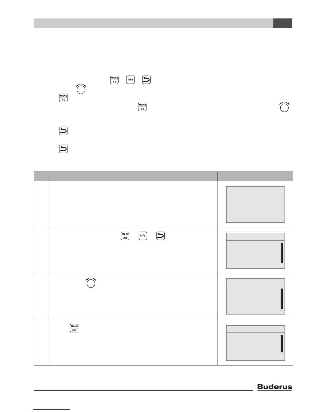
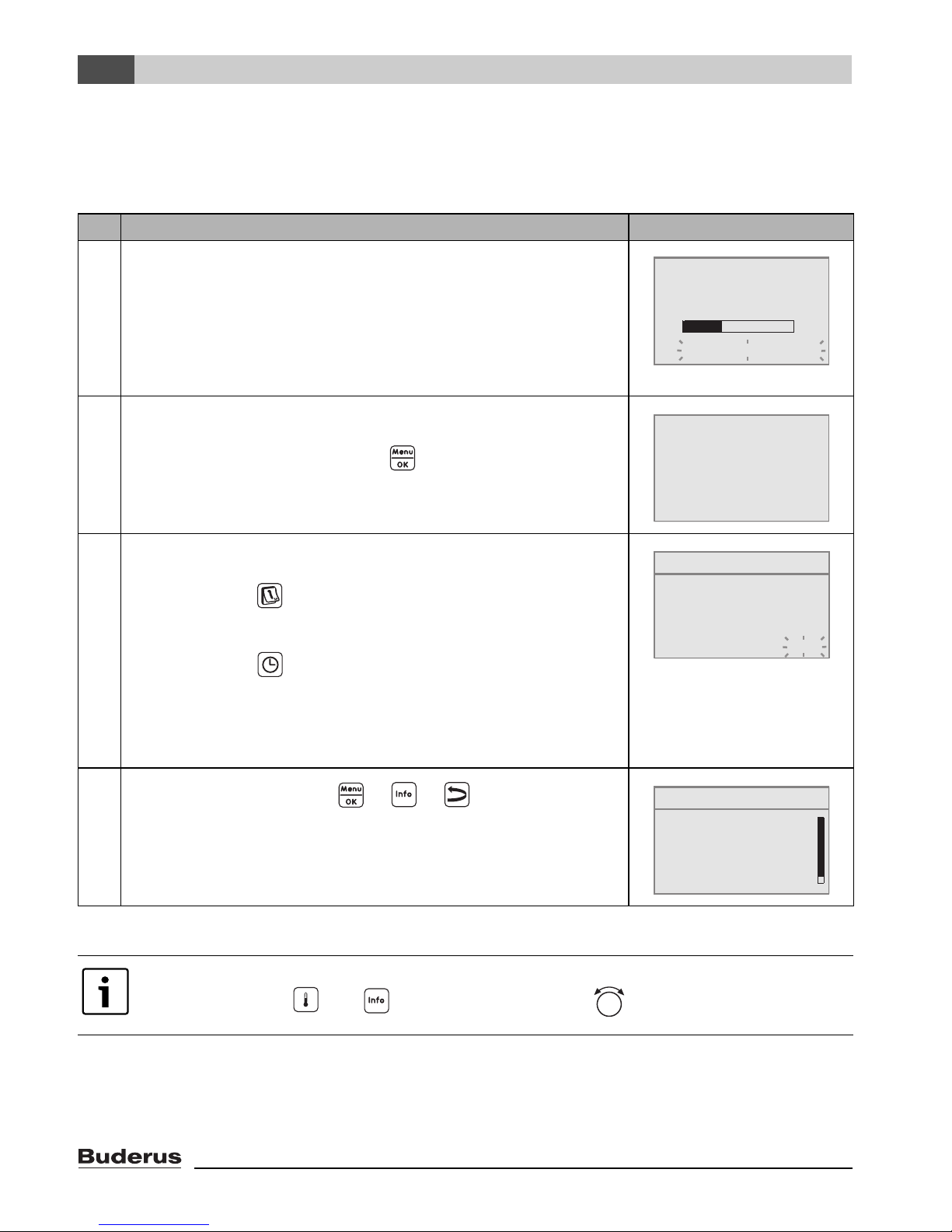
4.2 Introduction to the Service menu
The SERVICE MENU sets the system parameters. The Service menu also contains fault diagnosis,
for maintenance purposes, and performing a reset. The procedure for operation is always the same:
1. Open the cover (by pulling the recessed grip on the left).
2. Simultaneously press the + + buttons to open the SERVICE MENU.
3. Turn the dial to change the selected item (marked with).
4. Press to make your selection.
5. To change the value, hold down the button (the value starts flashing) and turn the dial
at the same time.
Release the button: the changed value is saved.
6. Press to go back one step.
-or-
7. Press several times or shut the cover to return to the default display.
Example: Setting the type of building (“delay” time)
Operating Instructions Result
1. Open the cover (by pulling the recessed grip on the left).
2.
Simultaneously press the + + buttons to open
the SERVICE MENU.
3.
Turn the dial counter-clockwise until settings is selected
(marked with).
4.
Press to confirm the selection.
The SERVICE\SETTINGS menu is opened.
Fr 12/02/2009 10:20am
outdoor tmp. 30°F
71 ˚F
SERVICE MENU
B
quick operation
settings
diagnosis
servicing
SERVICE MENU
quick operation
B
settings
diagnosis
servicing
SERVICE\SETTINGS
B
system data
boiler data
domestic hot water
heating zone 1
Tab. 4 How to use the Service menu (example)
Logamatic EMS RC35 user interface - Subject to technical modifications. 15
Page 16
4
Operating basics
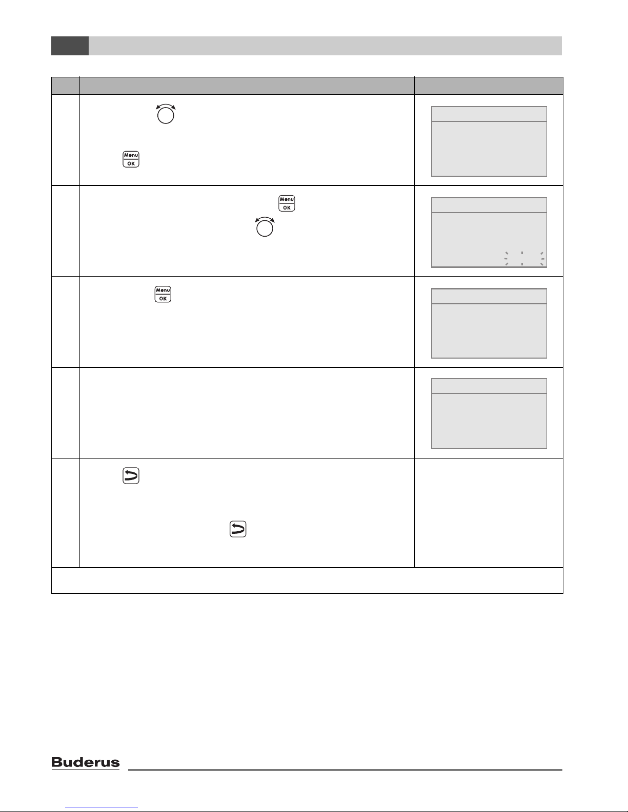
Operating Instructions Result
5.
Turn the dial counter-clockwise until system data is
selected (marked with).
SETTINGS\BOILER
What type of building
do you have?
Press to select system data.
6.
To change the value, hold down the button (the value
starts flashing) and turn the dial at the same time.
7.
Release the button.
The value stops flashing. The modified value is saved.
8. If you have carried out this example as practice only, make
sure that the original setting is retained.
To do so, repeat steps 6 and 7 if necessary.
medium
SETTINGS\BOILER
What type of building
do you have?
medium
SETTINGS\BOILER
What type of building
do you have?
light
SETTINGS\BOILER
What type of building
do you have?
medium
9.
Press to go back one step.
-or-
To finish entering settings, shut the cover.
The standard display re-appears.
You can enter all settings in the SERVICE MENU using this procedure.
Tab. 4 How to use the Service menu (example)
Logamatic EMS RC35 user interface - Subject to technical modifications.16
Page 17
Operating basics
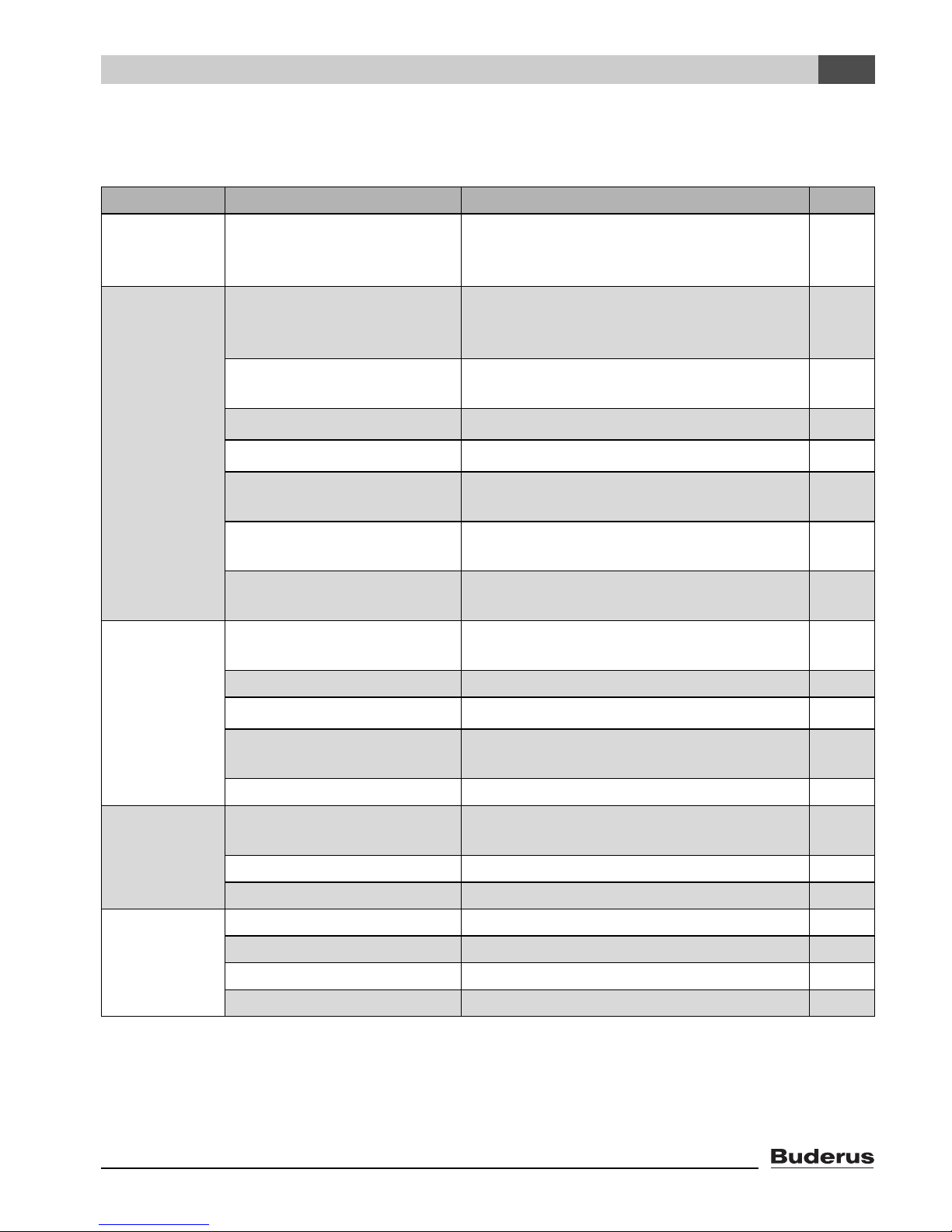
4.3 Overview of the Service menu
The SERVICE MENU is divided into the following menus and submenus:
Menu Submenu Contents/function Page
4
quick
operation
settings
(all
parameters)
diagnosis
The most important parameters from the
“settings” menu for configuration of the
heating system
system data
1)
Parameters: language, number of heating
zones, installed modules, building type,
minimum outdoor temperature
boiler data
1)2)
Parameters: pump after-run time and
modulation
heating zone data
1)
domestic hot water (DHW)
solar data
2)
Parameters of the installed heating zones 28
1)
Parameters for domestic hot water 37
If solar is installed: see documentation
for the solar module
RC35 calibration Parameters: calibration of the displayed
room temperature
contact data Entering the heating contractor's name
and telephone number
functional test
1)2)
Activating individual components for test
purposes
20
24
27
39
40
41
42
monitor value Viewing target values and actual values 43
error message
1)
Viewing fault messages 44
heating curve Viewing the set heating characteristics
in the form of a graph
versions Viewing software versions 45
servicing
1)2)
service interval Setting times for maintenance, by number
of operating hours or by date
current messages Viewing service messages 46
RESET service Resetting service messages 46
RESET
1)
factory default set Reset all parameters 47
fault list 47
service message 47
run time 47
Tab. 5 Service menu navigator
1) Subject to restrictions depending on which boiler is used.
2) Not possible or not available, depending on the boiler used.
45
46
Logamatic EMS RC35 user interface - Subject to technical modifications. 17
Page 18
5
Commissioning
5 Commissioning
5.1 General commissioning
Operation Result
1. Switch on the heating system.
While setting up the connection between the RC35 and EMS
the display shows the message on the right.
If the display shows a different message, look it up in
section 10, page 48.
2. Set the language:
Open the cover. Hold down the button and use the dial
to set the language.
3. Set the date and time:
Hold down the button and use the dial to set the values
that are flashing. Release the button.
Hold down the button and use the dial to set the values
that are flashing. Release the button.
RC35 version:
connect to:
connecting ...
please wait
Open cover to set
language using
OK key.
language set:
American
SET DATE
set year
01/01/2000
In the event of a power failure, the date and time are retained
for up to 8 hours. All other settings are retained permanently.
4.
Simultaneously press the + + buttons to open
the SERVICE MENU.
Tab. 6 General commissioning
If necessary, you can change the contrast on the display:
B Hold down the and buttons and turn the dial at the same time.
SERVICE MENU
B
quick operation
settings
diagnosis
servicing
Logamatic EMS RC35 user interface - Subject to technical modifications.18
Page 19

Commissioning
5
5.2 Checklist: important parameters for commissioning
When putting the device into service, ensure that the heating system settings meets the customer's
needs and expectations. In our experience, the following parameters are very important for the
satisfaction of the system owner.
B Find out the system owner's requirements and preferences regarding ...
Service menu\
Input range Factory setting
Settings\
... the desired setback
mode (night setback)
... the desired control
mode
... the correct heating
characteristics
... the correct type of
building (“delayed”
response to outdoor
temperature)
... the switch-on
frequency of the
DHW circulation pump
Outdoor setback mode
Room setback mode
setback mode
shutdown operation
outdoor reset control
room reset control
By means of the
following parameters:
standard temperature,
minimum outdoor
temperature, offset, and
target room temperature
light
medium
heavy
Permanent, 1 x, 2 x, 3 x,
4 x, 5 x, 6 x per hour for
3 min each time
Outdoor setback
mode
outdoor reset
control
heating zone x,
page 29
heating zone x,
page 32
heating zone x,
page 28
medium system data,
page 25
2 x domestic hot
water,
page 38
... DHW Priority yes
... program
(times)
Tab. 7 Checklist: important parameters for commissioning
Logamatic EMS RC35 user interface - Subject to technical modifications. 19
no
Standard program
e.g. family,
custom program
yes heating zone x,
page 30
family heating zone x,
page 31
Page 20

5
Commissioning
5.3 Quick commissioning (Quick operation menu)
B Press to open the quick operation menu.
SHORTCUT Menu item Input range
BASIC SETUP Which language should
be used?
American,
French,
Spanish
LOW LOSS
HEADER
UNMIXED HZ Is heating zone 1
Did you install a low
loss header module?
yes, no no In connection with
yes, no yes
installed (unmixed
heating zone)?
# OF MIX
VALVES
How many mixed
heating zones are
0 to 3 0 Set the address on the
installed?
SERVICE MENU
B
quick operation
settings
diagnosis
servicing
Factory
setting Other information
American
MCM10 the setting is
set automatically to
“yes”; the screen
disappears.
dial on the MM10 mixing
module
(factory setting: HZ2).
HEATING
ZONE 1
(and other heating
zones)
Which user interface is
assigned to heating
zone 1?
How should heating
zone 1 be controlled?
Which heating system
does heating zone 1
have?
Tab. 8 Quick operation menu navigator
RC20, RC35
none
outdoor reset,
room reset
panel radiator,
convector,
floor
RC35 To assign user interface
to heating zone
(Æ page 32).
outdoor
reset
General heating zone
data (Æ page 28).
Set any other heating
zones in the same way
as for heating zone 1.
panel
radiator
Heating characteristic
curve (Æ page 33)
Logamatic EMS RC35 user interface - Subject to technical modifications.20
Page 21

Commissioning
SHORTCUT Menu item Input range
5
Factory
setting Other information
DHW Is a DHW tank
installed?
What should be used
for domestic hot water
heating?
Please select the
domestic hot water
temperature.
SOLAR MODULE Has a solar module
been installed?
Tab. 8 Quick operation menu navigator
Use the checklist on page 19 to check whether more settings are needed.
yes, no no
low loss
header,
low loss
header
tank charging
pump
90 to 176 °F 140 °F To allow the hot water
temperature to be
changed, set the hot
water dial on the boiler
controller to Aut.
yes, no
5.4 Detailed commissioning
B Check whether the factory settings in the SERVICE\SETTINGS menu are suitable for the
customer's heating system.
B Write down modified settings for future reference in the Set Up Log.
5.5 System commissioning
B Make sure that both dials on the BC10 boiler controller are set to “Aut”, so that DHW
temperature and supply temperature are controlled by the RC35.
B Explain to the customer how the device works and how to operate it.
B Inform the customer of the settings chosen.
We recommend giving these installation and servicing instructions to the customer so
they can be kept close to the heating system.
Logamatic EMS RC35 user interface - Subject to technical modifications. 21
Page 22

5
Commissioning
5.6 Shut-down/switching off
The RC35 controls is supplied with power via the heating system and is permanently switched on.
It is only switched off if the heating system is switched off, such as for maintenance purposes.
B To switch the heating system on or off: set the ON/OFF switch on the boiler to position 1 (ON)
or 0 (OFF).
After switching the unit OFF or in the event of a power failure, the date and time are
retained for up to 8 hours. All other settings are permanently memorized.
Logamatic EMS RC35 user interface - Subject to technical modifications.22
Page 23

Commissioning
5
5.7 Operating tips
Devices on the EMS bus
In a bus system, only one device can carry out the calculations for a heating zone. Therefore only
one RC35 can be installed in a heating system. If additional room controllers are needed, they are
installed as remote control units with a designated heating zone (Æ page 28).
Thermostatic radiator valves in the reference room
With room temperature control, thermostat valves do not need to be installed on the radiators in the
1)
reference room
. If there are thermostatic radiator valves in the reference room, they must be fully
open at all times.
Pump anti-seize Feature
In all operating modes, all heating zone pumps are switched on for 10 seconds every Wednesday
at 12 noon to prevent pump damage. The mixing valves are then set to “OPEN” for 10 seconds and
then to “CLOSE”. After 10 seconds, all pumps and mixing valves then return to their normal,
regulated operation.
1) Room in which an RC35 is installed.
Logamatic EMS RC35 user interface - Subject to technical modifications. 23
Page 24

6
Entering system settings (Service menu – Settings)
6 Entering system settings (Service menu –
Settings)
B Simultaneously press the + + buttons to open the
SERVICE MENU.
B Turn the dial counter-clockwise until settings is selected
(marked with).
B Press to open the SERVICE\SETTINGS menu.
Note that the menu items shown will vary depending on the heating system.
6.1 System data
B Press to select system data.
The SETTINGS\SYSTEM menu opens.
Factory
Menu item Input range
setting Other information
SERVICE MENU
quick operation
B
settings
diagnosis
servicing
SERVICE\SETTINGS
B
system data
boiler data
domestic hot water
heating zone 1
Which language should be
used?
American,
French,
American
Spanish
Choose units of
measurement.
US customary units °F,
metric °C/bar
Choose time format: am/pm 24h
Choose date format: MM/DD/YYYY DD/MM/YYYY
Did you install a low loss
header module?
yes, no no In connection with MCM10 the
setting is set automatically to
“yes”; the screen disappears.
Is heating zone 1 installed
yes, no yes
(unmixed heating zone)?
How many mixed heating
zones are installed?
0 to 3 0 Set the address on the dial on the
MM10 mixing module
(factory setting: HZ2).
Has a solar module been
yes, no no
installed?
Tab. 9 Navigator for Service menu SETTINGS\SYSTEM
Logamatic EMS RC35 user interface - Subject to technical modifications.24
Page 25

Entering system settings (Service menu – Settings)
Menu item Input range
6
Factory
setting Other information
Confirm disabling the use of
the calculated outdoor
yes, no no If “yes”, the following parameter
(building type) is not shown.
temperature.
What type of building do you
have?
light,
medium,
medium For type of building (heat storage
capacity) (Æ page 25).
heavy
What is the design day
temperature in your region?
–40 °F – 32 °F
(–40 °C – 0 °C)
–14 °F (Æ page 26)
Tab. 9 Navigator for Service menu SETTINGS\SYSTEM
6.1.1 Type of building (“damping” of outdoor temperature)
A building's heat storage capacity and its characteristic resistance to heat transfer will delay the
effect of outdoor temperature variation on the rooms inside. As a consequence, it is not the current
outdoor temperature that is crucial to the heat demand of rooms, but the so-called “adjusted outdoor
temperature”.
The building type parameter can be used to set the level of delay with which variations in outdoor
temperature are registered. This allows the heating system control adapt to the characteristic
behavior of the building.
The controlls calculates the time constant for the delay in response to the outdoor temperature
Parameter:
building type Type of construction
light Buildings with small heat storage capacity and low to medium levels of
insulation, e.g. 2x4 wood frame or prefabricated construction with typical
insulation.
medium Buildings with medium heat storage capacity and high levels of insulation,
e.g. 2x6 wood frame or cinder block construction with above average insulation
(factory default).
heavy Massive buildings with high heat storage capacity and high levels of insulation,
e.g. poured concrete, heavy brick or heavy cinder block construction with
excellent insulation.
Tab. 10 Calculating the damping time constant
Logamatic EMS RC35 user interface - Subject to technical modifications. 25
Page 26

6
Example:
Entering system settings (Service menu – Settings)
Fig. 5 This greatly simplified example shows how the delayed response to outdoor temperature
follows the outdoor temperature, but does not reach its extreme values.
1 Current outdoor temperature
2 Adjusted outdoor temperature
With the factory setting, changes in the outdoor temperature will affect the calculations
for outdoor-temperature-based control after a delay of no more than three hours
(30 x 6 minutes = 180 minutes).
B To monitor the calculated, delayed response to outdoor temperature and the
currently recorded outdoor temperature:
open the menu Diagnosis\Monitor\boiler/burner.
6.1.2 Minimum outdoor temperature
The “minimum outdoor temperature” is the mean of all the coldest outdoor temperatures of recent
years, and helps to determine the heating characteristics. The value can be taken from the heat
requirement calculation that should be done for every building, or from the climatic zone chart of your
region.
Logamatic EMS RC35 user interface - Subject to technical modifications.26
Page 27

Entering system settings (Service menu – Settings)
6.2 Boiler data
6
B Turn the dial counter-clockwise until boiler data is selected
(marked with).
B Press to select boiler data.
The SETTINGS\BOILER menu opens.
Factory
Menu item Input range
Set boiler pump post
purge after burner stops?
deactivated,
1 to 60 min,
setting
5 min Setting only possible with boilers with
Other information
internal boiler pump.
24 hours
Please adjust modulating
pump settings.
0 to 8 2 Characteristics of the boiler pump
depend on the boiler installed
• 0: if a hydraulic low loss header has
been installed
• 1 – 8: see boiler documentation
Tab. 11 Navigator for Service menu SETTINGS\BOILER
SERVICE\SETTINGS
system data
B
boiler data
domestic hot water
heating zone 1
1)
1) system-dependent
Logamatic EMS RC35 user interface - Subject to technical modifications. 27
Page 28

6
Entering system settings (Service menu – Settings)
6.3 Heating zone data
This section explains the settings for all heating zones: using heating zone 1 as an example.
B Turn the dial counter-clockwise until
heating zone 1 is selected (marked with).
B Press to select heating zone 1.
The SETTINGS\HTG. ZONE 1 menu opens.
Menu item Input range
Should heating zone 1
yes, no yes
be activated?
Which user interface is
none, RC20, RC35 RC35 (Æ page 33)
assigned to heating
zone 1?
How should heating
zone 1 be controlled?
outdoor reset,
room reset
SERVICE\SETTINGS
system data
boiler data
domestic hot water
B
heating zone 1
Factory
setting
Other information
If none is selected, the control
mode is changed to outdoor reset
and will not be shown.
outdoor reset Room reset can only be set if an
RC20 or RC35 has been
assigned to the heating zone.
If there is one unmixed zone on a
system with a modulating burner,
the boiler power will used to
directly control the room
temperature; in all other cases the
supply temperature will be
controlled.
Which heating system
does heating zone 1
have?
panel radiator,
convector,
floor
panel radiator With HZ1, only use the floor
Heating curve
Design tmp
14 °F (-10 °C)
84 °F to 194 °F
(30 °C – 90 °C)
167 °F (75 °C)
(panel radiator,
convector)
113 °F (45 °C)
(floor)
Tab. 12 Navigator for Service menu SETTINGS\HTG. ZONE 1
Logamatic EMS RC35 user interface - Subject to technical modifications.28
setting if the boiler is a gas
condensing boiler. Additional
heating zones can then be
installed.
A safety thermostat must be used
with radiant floor heating
regardless.
Setting entered only if the control
mode has been set to outdoor
reset (Æ page 33).
Page 29

Entering system settings (Service menu – Settings)
Factory
Menu item Input range
setting Other information
6
max.supply temp. panel radiator,
convector:
86 °F – 194 °F
Enter the maximum
supply
temperature:
(30 °C – 90 °C)
floor:
86 °F – 140 °F
(30 °C – 60 °C)
min.supply temp. 41°F– 158°F
(5 °C – 70 °C)
Enter the minimum
supply
temperature:
room tmp.offset –9 °F – +9 °F
(–5 °C – +5 °C)
Enter the maximum
room influence:
0°F– 18°F
(0 °C – 10 °C)
panel radiator,
convector:
167°F (75°C)
floor:
122 °F (50 °C)
Setting entered only if the control
mode has been set to outdoor
reset (Æ page 32)
Setting entered only if the control
mode has been set to room temp.
controlled (Æ page 32).
41 °F (5 °C) Setting entered only if the control
mode has been set to outdoor
reset (Æ page 32)
Setting entered only if the control
mode has been set to room temp.
controlled (Æ page 32).
0 °F (0 °C) Parallel shifting of characteristic
heating curve.
Setting entered only if the control
mode has been set to outdoor
reset (Æ page 32)
0 °F (0 °C) Setting entered only if the control
mode has been set to outdoor
reset (Æ page 32)
Select the type of
setback:
Outdoor setback
mode, setback
Outdoor
setback mode
operation, Room
setback mode (only if
RC35 or RC20 has
been assigned to the
heating zone)
What outdoor temp.
should be used for
–4 °F – +50 °F
(–20 °C – +10 °C)
41 °F (5 °C) Temperature threshold for outdoor
setback operation?
Frost protection
Set temperature for
frost protection.
outdoor temperature
no frost protection
outdoor
temperature
room temperature
Tab. 12 Navigator for Service menu SETTINGS\HTG. ZONE 1
Night setback (Æ page 34)
setback mode (Æ page 34).
Setting entered only if the
reduction mode has been set to
outdoor setback mode.
Room temperature can only be set
if RC20 or RC35 has been
assigned to the heating zone
(Æ page 35).
Logamatic EMS RC35 user interface - Subject to technical modifications. 29
Page 30

6
Entering system settings (Service menu – Settings)
Menu item Input range
Factory
setting Other information
Set temperature for
frost protection.
At what outdoor
temp. should the
setback be
–4 °F – +50 °F
(–20 °C – +10 °C)
OFF,
–22 °F – 50 °F
(–30 °C – +10 °C)
canceled?
Confirm activating
yes, no no
DHW priority.
Mixing valve
Is a mixing valve
yes, no yes Can only be set for heating
installed?
What is the run
10 – 600 seconds 120 seconds
time of the mixing
valve?
What increase
should be used for
0°F– 36°F
(0 °C – 20 °C)
the boiler?
Drying floor radiant slab
Confirm running a
yes, no no Can only be set if radiant floor
slab drying cycle.
41 °F (5 °C) Refers to outdoor temperature
(Æ page 35).
OFF
zones 2 and up.
10 °F (5 °C)
heating has been entered as the
heating system. DHW heating is
disabled while slab is drying.
Set the frequency
for raising the
every day, every 2nd
day to every 5th day
daily
supply
temperature.
Set the supply
temperature
0°F– 72°F
(0 K – 40 K)
9°F (5°C)
increase.
Set the maximum
supply
77 °F – 140 °F
(25 °C – 60 °C)
113 °F (45 °C)
temperature.
For how many days
0 – 20 days 4 days
should max. supply
temp. be
maintained?
Tab. 12 Navigator for Service menu SETTINGS\HTG. ZONE 1
Logamatic EMS RC35 user interface - Subject to technical modifications.30
Page 31

Entering system settings (Service menu – Settings)
Factory
Menu item Input range
setting Other information
6
Set the frequency
for reducing the
supply
temperature.
Set the supply
temperature
decrease.
Confirm changing the
program?
Should the program be
optimized?
What setback mode
should be used for
vacation / absence?
direct normal operat.,
every day
every day,
every 2nd day to
every 5th day
0°F– 36°F
(0 °C to 20 °C)
9 °F (5 °C) Can only be set if direct normal
operat. has not been entered for
supply temperature reduction.
yes, no no Selecting “yes” takes you to the
program for the heating zone.
yes, no no Switch-on and switch-off times
are automatically adjusted
according to the outdoor
temperature, room temperature
and building type (heat storage
capacity).
Outdoor setback
mode
Room setback mode
setback mode
shut-down mode
Outdoor
setback mode
Æ page 34.
Room setback mode can only be
set if a remote control unit
(e.g. RC20) has been assigned to
the heating zone.
What outdoor temp.
should be used in
–4 °F – +50 °F
(–20 °C – +10 °C)
41 °F (5 °C) Temperature threshold for outdoor
vacation mode?
Tab. 12 Navigator for Service menu SETTINGS\HTG. ZONE 1
If setback mode is selected the
normal night temperature is used.
setback mode (Æ page 34).
Setting entered only if the reduction mode for vacation has been
set to Outdoor setback mode.
Logamatic EMS RC35 user interface - Subject to technical modifications. 31
Page 32

6
Entering system settings (Service menu – Settings)
6.3.1 Assignment of user interface/remote control unit in the software
Example: heating system with heating zone 1 and heating zone 2 (Æ page 11)
Alternative Setting: Which remote control is
Effect
assigned to the heating zone?
A HZ 1 = RC35, HZ 2 = RC35
Same room temperatures for HZ 1 and HZ 2
(Æ Fig. 2, [1], page 11)
B HZ 1 = RC35, HZ 2 = none
(Æ Fig. 2, [1], page 11)
Room temperatures for HZ 1 and HZ 2 can
be set separately
Tab. 13 Settings for room temperature depending on user interface
6.3.2 Control mode (outdoor temperature controlled/room influence)
The temperature of the heating water in the boiler is defined by the heating characteristics
determined in the Logamatic controls. A selection can be made whether these heating
characteristics will be influenced solely by the outdoor temperature, or by a combination of outdoor
temperature and room temperature.
• Outdoor temperature controlled: The boiler temperature calculated in the controls will be
controlled by variation in the “delayed” response to outdoor temperature in combination with
selected settings for target room temperature, offset, standard temperature and minimum
outdoor temperature. This temperature is then delivered to the radiators or radiant floor heating
by means of permanent operation of the heating zone pump. The only situations in which this
setting could result in shut-down of the heating zone pump are summer operation, night setback
(depending on the reduction mode selected) or DHW mode (only with domestic hot water
priority).
• Outdoor temperature controlled, influenced by room temperature (factory default):
this form of control works in exactly the same way as pure outdoor temperature control, except
that you can use the maximum room influence parameter to determine whether and to what
extent the room temperature should influence the heating characteristics.
The remote control unit must be installed in a reference room, so that a representative room
temperature is recorded.
The greater the parameter set, the greater the influence of the room temperature on the heating
characteristics (factory setting: 0 °F (0 °C)). This applies when the room temperature exceeds or
falls below the target room temperature. If the maximum room influence parameter is set to 0,
the heating characteristics will be controlled solely by outdoor temperature.
Logamatic EMS RC35 user interface - Subject to technical modifications.32
Page 33

Entering system settings (Service menu – Settings)
6
6.3.3 Characteristic heating curve
Parameters: Standard temperature, maximum and minimum supply temperature and room
temperature offset (parallel shifting of characteristic heating curve)
The characteristic heating curve forms the basis for economical and easy operation of the heating
system with outdoor reset. To calculate the characteristic heating curve, the Logamatic control uses
a number of parameters.
This calculation takes into account the “delayed” response to outdoor temperature changes and the
room temperature. The room temperature is internally calculated, based on target room temperature
and the room influence factor.
This allows the user to influence the heating characteristics directly by modifying the target room
temperature.
The heating characteristic curve (Æ Fig. 6, page 34) is determined by the base point and end point.
The base point is located at 14 °F (–10 °C) supply temperature at a room temperature of 68 °F
(20 °C). The end point of the heating characteristic curve must be set in accordance with the design
temperature of the heating system.
The gradient of the heating characteristic curve (the shape of the curve) is determined by the parameters minimum outdoor temperature (the lowest outdoor temperature expected in a particular
region, Æ page 26) and the standard temperature (the supply temperature which should be
reached when the outdoor temperature is at minimum) (Æ Fig. 6, left).
The x-axis of the heating characteristic curve shown on the display covers the range
from +68 °F to –4 °F (+20 °C to –20 °C). With the parameter std. tmp., the minimum
outdoor temperature is represented by a circle. However, the diagram will not be quite
correct if a minimum outdoor temperature below –4 °F (–20 °C) is entered (the circle
will no longer be on the heating characteristic curve).
The minimum supply temperature parameter can be used to define a minimum target value
(Æ Fig. 6, [4]). If the temperature falls below this value, the burner is fired.
The characteristic heating curve can be shifted, up or down, in parallel to the original curve, by
adjusting the room temperature offset parameter and/or the set room temperature
(Æ Fig. 6, right). This feature should be used if, for example, the room temperature measured with
a thermometer differs from the set target value.
Logamatic EMS RC35 user interface - Subject to technical modifications. 33
Page 34

6
Entering system settings (Service menu – Settings)
Fig. 6 Setting the characteristic heating curve
Left: setting the gradient by means of standard temperature and design day temperature
Right: parallel shift possible by means of offset or target room temperature
T
T
1 Setting: design temperature 167 °F (75 °C), minimum outdoor temperature 14 °F (–10 °C) (base curve)
2 Adjustment: Design temperature 167 °F (75 °C), minimum outdoor temperature 4 °F (–20 °C)
3 Adjustment: Design temperature 122 °F (50 °C), minimum outdoor temperature 14 °F (–10 °C)
4 Setting: minimum supply temperature 95 °F (35 °C)
5 Setting: design temperature 167 °F (75 °C), minimum outdoor temperature 14 °F (–10 °C) (base curve)
6 Parallel shifting of base curve by changing the offset +6 °F (+3 °C) or by increasing the target room
7 Parallel shifting of base curve by changing the offset –6 °F (–3 °C) or by reducing the target room
Minimum outdoor temperature
minA
Standard temperature (i.e. the design temperature – the supply temperature to be reached at design day
A
temperature)
temperature
temperature
6.3.4 Reduction modes (night setback)
There are a number of different reduction modes available, which allow night setback to be adjusted
to suit the differing needs of the user:
• setback mode: The rooms are maintained at a reasonable temperature by constant heating
operation (the heating zone pump runs constantly). A target room temperature for nighttime can
be set. This must be at least 2 °F (1 °C) lower than the daytime target room temperature. The
heating characteristics will be calculated in accordance with this setting.This setting is
recommended for radiant floor heating.
Logamatic EMS RC35 user interface - Subject to technical modifications.34
Page 35

Entering system settings (Service menu – Settings)
6
• shut-down mode: The boiler and the heating zone pump are switched off, and frost protection
is activated. The heating zone pump runs only for purposes of frost protection. Not recommended
if there is a risk that the building could cool down too much.
• Room setback mode: If the room temperature falls below the set night temperature (the target
value), the heating system will operate in the same way as for reduced heating operation (as
described under reduction mode “setback mode”). If the room temperature exceeds the target
night temperature by more than 2 °F (1 °C), the boiler and the heating zone pump are switched
off (as described under reduction mode “shut-down mode”). This reduction mode is only possible
if a remote control unit has been installed in a representative room (the reference room) or if the
room temperature is recorded using an external room sensor.
• Outdoor setback mode: If the “delayed” response to outdoor temperature falls below a user-
defined threshold, the heating system will operate in the same way as for reduced heating
operation (as described under “setback mode”). Above this threshold, the heating system will be
switched off (as described under reduction mode “shut-down mode”). This reduction mode is
suitable for heating zones that do not have their own remote control unit, and protects the rooms
from cooling down too much once a certain outdoor temperature is reached.
6.3.5 Frost protection
The frost protection function comprises the following options:
• no frost protection (frost protection is switched off)
• outdoor temperature (outdoor temperature sensor required) If the outdoor temperature falls
below the adjustable frost protection temperature threshold, the heating zone pump is switched
on automatically.
• room temperature (room temperature sensor in the RC35 or RC20) If the room temperature
falls below the fixed value of 41 °F (5 °C), the heating zone pump is switched on automatically. If
the room temperature rises above 44 °F (7 °C), the heating zone pump is switched off
automatically.
CAUTION: Risk of system damage due to freezing. The settings no frost protection
and room temperature provide either no frost protection or inadequate frost
protection. When these settings are selected, the display shows a message indicating
the risk of freezing.
B For reliable frost protection, use the outdoor temperature setting.
The room temperature setting does not provide absolute frost protection because
pipes laid in external walls (for example) could freeze even though the temperature in
the reference room might be clearly above 41 °F (5 °C) due to external heat sources
(fireplace etc.).
Logamatic EMS RC35 user interface - Subject to technical modifications. 35
Page 36

6
Entering system settings (Service menu – Settings)
At what outdoor temperature should setback be cancelled?
In the parameter At what outdoor temp. should the setback be canceled?, you can set an
outdoor temperature threshold (this threshold applies to the “delayed” response to outdoor
temperature; Æ page 25).
Fig. 7 shows how the frost protection function works, without this parameter activated and with it
activated. Settings selected: frost protection by outdoor temperature; frost protection
temperature 41 °F (5 °C).
Fig. 7 Effects of the parameter “At what outdoor temperature should reduction be interrupted?”
Left: parameter is set to “OFF” (factory setting)
Right: parameter is set to 5 °F (–15 °C)
T
T
1 Shutdown operation
2 Reduced operation (at set nighttime room temperature)
3 Heating operation (at set daytime room temperature)
Outdoor temperature
A
Supply temperature
V
If the outdoor temperature falls below the set value of 6 °F (–15 °C), heating switches from reduced
operation to heating operation (Æ Fig. 7, [3]). This allows smaller heating surfaces to be utilized.
Logamatic EMS RC35 user interface - Subject to technical modifications.36
Page 37

Entering system settings (Service menu – Settings)
6.4 Domestic hot water (DHW)
WARNING: Risk of scalding at the taps.
There is a risk of scalding at the taps whenever domestic hot water temperatures can
be set to more than 122 °F (50 °C), and also during thermal disinfection.
B Make sure that a thermostatic mixing valve is installed and that it is set to
temperatures below 122 °F (50 °C).
6
B Turn the dial counter-clockwise until domestic hot water
is selected (marked with).
B Press to select domestic hot water.
The SETTINGS\DHW menu opens.
Factory
Menu item Input range
setting Other information
Is a DHW tank installed? yes, no no
Set maximum DHW
temperature:
Please select the domestic
hot water temperature.
What should be used for
domestic hot water heating?
140°F– 176°F
(60 °C – 80 °C)
86 °F to 176 °F
(30 °C – 80 °C)
Selection of 3-way
switching valve vs
140 °F (60 °C) Depending on the boiler,
140 °F (60 °C) If the limit is set to
3-way valve
tank primary pump
SERVICE\SETTINGS
system data
boiler data
domestic hot water
B
heating zone 1
the max. possible DHW
target temperature is
limited to 140 °F (60 °C).
> 140 °F (> 60 °C), it will
be possible to set
temperatures of that level
in the User menu as well.
Confirm changing the DHW
program.
Recirculation
Is a recirculation pump
installed?
Tab. 14 Navigator for Service menu SETTINGS\DHW
Logamatic EMS RC35 user interface - Subject to technical modifications. 37
yes, no no Selecting “yes” takes you
to the program for
domestic hot water.
yes, no no
Page 38

6
Entering system settings (Service menu – Settings)
Menu item Input range
Factory
setting Other information
Specify the frequency of
the recirculation pump
per hour.
once for 3 minutes,
twice for 3 minutes,
3 times for 3 minutes,
twice for
3 minutes
4 times for 3 minutes,
5 times for 3 minutes,
6 times for 3 minutes,
permanent operation
run recirc pump Graphical display of
number of times the pump
is switched on per hour.
Confirm changing the
recirculation program.
yes, no no Selecting “yes” takes you
to the program for hot
water circulation.
Thermal disinfection
Confirm performing a
yes, no no
thermal disinfection.
Set thermal disinfection
temperature.
140°F– 176°F
(60 °C – 80 °C)
1)
158 °F (70 °C) At temperatures above
122°F (50°C) there is a
risk of scalding at the taps
during and after thermal
disinfection.
Set the day of the thermal
disinfection.
Monday, Tuesday,
Wednesday,
Tuesday
Thursday, Friday,
Saturday, Sunday,
daily
Set the time of day of the
thermal disinfection.
12:00 am – 11:00 pm 1:00 am Times entered must
be whole hours only
(no minutes).
Should the LED of the single
charge key be activated?
yes, no yes The single charge function
(for one-off heating of
hot water) still works but
is no longer indicated by
an LED.
Tab. 14 Navigator for Service menu SETTINGS\DHW
1) Depending on the boiler, a fixed temperature is defined and it cannot be changed.
Logamatic EMS RC35 user interface - Subject to technical modifications.38
Page 39

Entering system settings (Service menu – Settings)
6.5 Solar data
In order for the solar menu to become available, under SETTINGS\SYSTEM the
question: “Has a solar module been installed?” must be answered with “yes”.
6
B Turn the dial counter-clockwise until solar data is selected
(marked with).
B Press to select solar data.
The SETTINGS\SOLAR menu opens.
SERVICE\SETTINGS
boiler data
domestic hot water
heating zone 1
B
solar data
Menu item Input range Factory setting
Set the maximum solar tank
temperature.
Set the minimum solar tank
temperature.
86 °F – 194 °F
(30 °C – 90 °C)
86 °F – 130 °F
(30 °C – 54 °C)
140 °F
OFF
OFF
What is the minimum pump rating? 20 % – 100 % 30 %
Tab. 15 Navigator for Service menu SETTINGS\SOLAR
For explanations of the settings, see the documentation for the SM10 solar module.
Other
information
Logamatic EMS RC35 user interface - Subject to technical modifications. 39
Page 40

6
Entering system settings (Service menu – Settings)
6.6 RC35 calibration
B Turn the dial counter-clockwise until RC35 calibration is
selected (marked with).
B Press to select RC35 calibration.
The SETTINGS\CALIB. RC35 menu is opened.
SERVICE\SETTINGS
domestic hot water
heating zone 1
solar data
B
RC35 calibration
Menu item Input range Factory setting Other information
Calibration of the room
temperature
–9.0 °F – +9.0 °F
(–5.0 °C – +5.0 °C)
0.0 °F (0.0 °C)
Tab. 16 Navigator for Service menu SETTINGS\CALIB. RC35
Calibration of the displayed room temperature
If there is a separate thermometer near the controls, it may show a different room temperature to that
shown on the RC35. This function can be used to adjust the RC35 to match the thermometer
(i.e. “calibrate”).
Before calibrating the room temperature, consider the following:
• Is the thermometer more accurate than the RC35?
• Is the thermometer located close to the unit so that they are both subject to the same heat
influences (e.g. sunlight, fireplace)?
Other thermometers may show temperature changes more slowly or more quickly than
the RC35.
B Never calibrate the controls when your heating system is in the process of cooling
down or heating up, but only in steady state conditions.
Example: if the thermometer is showing a temperature 2 °F (1 °C) higher than the controls, enter
“+2 °F (+1 °C)” as the calibration value.
Logamatic EMS RC35 user interface - Subject to technical modifications.40
Page 41

Entering system settings (Service menu – Settings)
6
6.7 Contact data
The details entered in “Contact data” are automatically displayed to the customer in the event of a
fault. Use this feature to alert the homeowner to call your 24 hour service hotline.
B Turn the dial counter-clockwise until contact data is selected
(marked with).
B Press to select contact data.
The menu SETTING\CONTACT is opened.
SERVICE\SETTINGS
heating zone 1
solar data
RC35 calibration
B
contact data
Menu item Input range Other information
Name and phone # of
heating contractor:
_ _ _ _ _ _ _ _ _ _ _
_ _ _ _ _ _ _ _ _ _ _
Tab. 17 Navigator for Service menu SETTING\CONTACT
Entering company name and telephone number
Two rows are available, each with 21 characters (capital letters, numbers and some other symbols).
The current cursor position will flash (marked by).
1. Hold down the button and turn the dial simultaneously to select another character.
Release the button: the modified character is saved.
2. Turn the dial counter-clockwise or clockwise to move the cursor.
3. To delete a character, enter a space.
4. Press to save your entries and leave the menu.
Logamatic EMS RC35 user interface - Subject to technical modifications. 41
Page 42

7
Diagnosis
7 Diagnosis
The Diagnosis service menu contains a number of diagnostic tools:
• Function test
• Monitor value
• Error message
• Characteristic heating curve
• Version information
B Simultaneously press the + + buttons to open the
SERVICE MENU.
B Turn the dial counter-clockwise to select Diagnosis
(indicated by).
SERVICE MENU
quick operation
settings
B
diagnosis
servicing
B Press to open the SERVICE\DIAGNOSIS menu.
Note that the menu items shown will vary depending on the heating system.
7.1 Function test
Use this menu to activate separate EMS components individually in order to test their functions.
The available functions and the possible settings vary depending on the system installed.
B Hold down the button and turn the dial at the same time to
change the setting: e.g. BURNER OFF to BURNER ON.
The change takes effect when you release the button.
FUNCT. TEST\BOILER
valve 1 clsed 2 clsed
ignition OFF
flame OFF
flame current 0.0μA
B
BURNER ON
B Turn the dial to switch between different displays (for function
tests).
Be mindful of the information which appears on the display when you switch to menus
or when you enter settings. Press any of the buttons or turn the dial to confirm the
information.
FUNCT. TEST\BOILER
act. boilertmp. 140°F
air temperature 90°F
flue gas temp. 172°F
flame OFF
B
BURNER OFF
Logamatic EMS RC35 user interface - Subject to technical modifications.42
Page 43

Diagnosis
7
No settings are available that might result in damage to the components. This is why
some settings may not be accepted.
7.2 Monitor value
Use the monitor value menu to view the target and actual values for the heating system. The target
value will be displayed first and then the actual value. The values displayed for monitoring purposes
vary depending on the system installed.
If the values to be displayed do not all fit on the screen, they are displayed as a list. Scroll
down the list by turning the dial.
DIAGNOSIS\MONITOR Other information
boiler/burner
MCMC10/cascade Only in conjunction with a MCM10 burner
(in position “boiler/burner”)
boiler
1)
Only in conjunction with a MCM10 burner
(in position “boiler/burner”)
low loss header
domestic hot water
heating zone 1 Values for other heating zones are displayed if such zones are
installed.
solar
bus users
Tab. 18 Navigator for the monitor value menu
1) The monitor values are displayed per boiler on an individual screen. By turning the dial, the monitor values
for the next boiler are called up.
Symbol present = corresponding function is active. Key to symbols Æ Tab. 19, page 44.
Logamatic EMS RC35 user interface - Subject to technical modifications. 43
Page 44

7
Diagnosis
Burner on
Heat demand
DHW demand
Flue gas test
service due / error
Tab. 19 Key to symbols for footnote 1), page 43
7.3 Error message
The most recent fault from the fault memory can be displayed using the error message
(e.g. to investigate a fault).
The faults are divided into the following categories:
• Current faults are all unresolved faults currently present in the system. These can be one of the
following types: locking, blocking or system error.
• Locking faults: When the fault is remedied, the heating system needs to be unlocked manually.
To do so, press the Reset button on the boiler.
• Blocking type faults: With blocking faults, the heating system resumes operation automatically as
soon as the fault has been rectified.
• System faults in the heating system are logged in the RC35, with the exception of faults in the
boiler or the burner, which are either “locking” faults or “blocking” faults errors. The heating
system continues to run – where possible – during the fault state; no reset is necessary.
For a list of the locking and blocking faults, which vary depending on the boiler, see the
installation and maintenance instructions of the boiler.
B Turn the dial to show the next message.
Logamatic EMS RC35 user interface - Subject to technical modifications.44
Page 45

Diagnosis
7
7.4 Characteristic heating curve
Use the heating curve menu to view the characteristics of each heating zone in the form of a graph.
B If the system has more than one heating zone: turn the dial to
view the characteristic heating curve for the next zone.
DIAG.\HEATG.CURVE HZ2
194
70
targ.supply tmp 135°F
7.5 Versions
You can use the INFO\VERSIONS menu to view the software versions for heating system
components.
B If the information cannot be displayed in one screen: turn the dial to
display the next screen.
INFO\VERSIONS
RC35 1.02
UBA3.5 1.21
Logamatic EMS RC35 user interface - Subject to technical modifications. 45
Page 46

8
Service
8 Service
The servicing menu is used to set a service interval and to view and reset current service messages.
The interval can be set to expire either after a given number of operating hours or when a given date
is reached. The RC35 will then show a message so that the customer can notify the heating
contractor to arrange an appointment.
Service messages are indicated by an Hxx code, e.g. H07.
SERVICE MENU\
SERVICE Menu item Input range
service interval How should
servicing
messages be
no messages,
by run time,
by date
triggered?
Factory
setting
no
messages
Other
information
Selecting “run time”
or “date” takes you
automatically to the
corresponding
setting.
For “by date”:
Annual servicing,
starting on:
01/01/2009 01/01/2009 To set the date:
hold down and
turn the dial at the
same time.
For “by operation
hours”:
Boiler operation
1000 h – 6000 h 6000 h Number of hours of
operation with burner
switched on
hours until next
servicing message
current messages Message/code To view further
messages: turn the
dial.
RESET service Confirm resetting
the service
messages.
Tab. 20 Navigator for the Servicing menu
no, yes no If you select “yes” the
servicing messages
will be reset.
Observe information
in display.
Logamatic EMS RC35 user interface - Subject to technical modifications.46
Page 47

Reset
9 Reset
The SERVICE MENU\RESET resets the following:
• All parameters back to their factory settings
• Fault list
• Service messages
• The run time.
After resetting parameters to the factory setting, the parameters may need to be
adjusted again to suit the system configuration.
B Turn the dial to select a menu, e.g. fault list. Press to go to the relevant screen, e.g.
Confirm resetting the list of faults. Press and turn the dial to set the display to yes.
When the button is released, the reset is carried out.
During this process, a corresponding message appears, which disappears again automatically.
9
B Once reset is complete: confirm by pressing any of the buttons.
Logamatic EMS RC35 user interface - Subject to technical modifications. 47
Page 48

10
Troubleshooting
10 Troubleshooting
This fault table lists possible “system errors”, i.e. faults of heating system components. The heating
system keeps operating as much as possible in the event of a system error; in other words, heating
of the home can continue as long as it is safe.
Use only original Buderus parts. Losses caused by the use of parts not supplied by
Buderus are excluded from the Buderus warranty.
The faults displayed will vary depending on the specific type of boiler in use.
Abbreviations used:
SC = Service code; x = heating zone with the number x, e.g. A23 for heating zone 3
FC = Fault code
HZx = Heating zone with the number x
Fault
SC FC
message
A01 800 Outdoor
sensor
defective.
Effect on control
characteristics Possible cause Remedy
The minimum outdoor
temperature is used
instead of the actual
outdoor temperature.
Tab. 21 Fault table
Sensor incorrectly
connected or
installed.
Break or short circuit
in the sensor lead.
Temperature sensor
is defective.
B Check the sensor
connection and the
sensor lead.
B Check that the
sensor is correctly
mounted.
B Compare resistance
values with the
characteristic
sensor curve.
Logamatic EMS RC35 user interface - Subject to technical modifications.48
Page 49

Troubleshooting
10
Fault
SC FC
message
A01 808 DHW
sensor 1
defective.
A01 809 DHW
sensor 2
defective.
A01 810 DHW stays
cold.
Effect on control
characteristics Possible cause Remedy
Heating of domestic hot
water is stopped.
Sensor incorrectly
connected or
installed.
Breakage or short
circuit in the sensor
lead.
Temperature sensor
is defective.
B Check the sensor
connection and the
sensor lead.
B Check that the
sensor is correctly
mounted.
B Compare resistance
values with the
characteristic
sensor curve.
The system continuously
attempts to heat the
DHW tank to the set
target temperature for
DHW.
DHW priority is switched
off once this fault
message appears.
Constant drawing or
system leak.
Sensor incorrectly
connected or
installed.
Breakage or short
circuit in the sensor
lead.
Temperature sensor
is defective.
B Fix any leaks
B Check the sensor
connection and the
sensor lead.
B Check that the
sensor is correctly
mounted.
B Compare resistance
values with the
characteristic
sensor curve.
Tab. 21 Fault table
DHW pump
incorrectly connected
or defective.
B Check that the
DHW pump is
working, e.g. by
carrying out a
function test.
Logamatic EMS RC35 user interface - Subject to technical modifications. 49
Page 50

10
Troubleshooting
Fault
SC FC
message
A01 811 Thermal
disinfection was
unsuccessful.
Effect on control
characteristics Possible cause Remedy
Thermal disinfection has
been interrupted.
Water draw too great
during the
disinfection period.
Boiler output is too
B Select a time for
thermal disinfection
when there is no
other demand heat.
low for heat to be
used for other
purposes at the same
time (e.g. 2nd heating
zone).
Sensor incorrectly
connected or
installed.
Breakage or short
circuit in the sensor
lead.
Temperature sensor
is defective.
B Check the sensor
connection and the
sensor lead.
B Check that the
sensor is correctly
mounted.
B Compare resistance
values with the
characteristic
sensor curve.
A01 816 No
communication with
UBA3/
MC10/
MCM10
A01 828 Water
pressure
sensor
defective.
A02 816 No
communication with
BC10
The boiler no longer
receives heat demand
signals; the heating
system no longer provides
heat.
BC10 settings are no
longer accepted by RCxx
devices.
DHW pump is faulty. B Check that the
DHW pump is
working, e.g. by
carrying out a
function test.
EMS bus system is
overloaded.
UBA3/MC10/
MCM10 is defective.
B Reset by switching
the heating system
on and off.
B Notify customer
support if needed.
Digital water pressure
sensor is defective.
Contact problem on
BC10, or BC10
faulty.
B Replace the water
pressure sensor.
B Check BC10
connection.
B Replace BC10 if
necessary.
Tab. 21 Fault table
Logamatic EMS RC35 user interface - Subject to technical modifications.50
Page 51

Troubleshooting
10
Fault
SC FC
message
A11 801 internal
error
A11 802 Time not
set.
A11 803 Date not
set.
A11 804 internal
error
A11 806 Room
temperature sensor
defective.
Effect on control
characteristics Possible cause Remedy
Heating system is in
emergency mode.
Restricted functionality
for:
• All programs
Internal runtime error
in the RC35.
Time details are
missing, e.g. due to
lengthy power failure.
B Replace RC35.
B Enter the current
time.
• Fault messages
Restricted functionality
for:
• All programs
Date details are
missing, e.g. due to
lengthy power failure.
B Enter the current
date.
• Vacation function
• Fault messages
Heating system is in
emergency mode.
Since the actual room
temperature is missing,
the following functions do
not work:
• Room influence
Internal runtime error
in the RC35.
Built-in temperature
sensor on the RC35
controls/remote
control unit is
defective.
B Replace RC35.
B Replace the remote
control unit.
(for outdoor
temperature control)
A12 815 Sensor
separator
module is
defective.
Tab. 21 Fault table
• Switch point
optimization
In the case of room
temperature control, the
system is regulated to
max. temperature for HZx.
Effects include
inadequate supply to
downstream heating
zones as they can no
longer be supplied with
the requested heat
amount.
Sensor incorrectly
connected or
installed. Breakage or
short circuit in the
sensor lead.
Temperature sensor
is defective.
B Check the sensor
connection and the
sensor lead.
B Check that the
sensor is correctly
mounted.
B Compare resistance
values with the
characteristic
sensor curve.
Logamatic EMS RC35 user interface - Subject to technical modifications. 51
Page 52

10
Troubleshooting
Fault
SC FC
message
A12 816 No
communication with
LL header
module.
A2x 806 Room
temperature
for HZx
defective.
Effect on control
characteristics Possible cause Remedy
Heating zone pump 1 is
permanently activated.
WM10 or bus cable
is incorrectly
connected or
faulty.WM10 not
B Check terminals on
WM10 and check
bus cable.
B Replace WM10.
recognized by RC35.
Since the actual room
temperature is missing,
the following functions do
not work:
• Room influence
Built-in temperature
sensor on the RC35
controls/remote
control unit is
defective.
B Replace the remote
control unit.
(for outdoor
temperature control)
• Switch point
optimization
In the case of room
temperature control, the
system is regulated to
max. temperature for HZx.
A2x 842 Frost
protection
w/o remote
HZx.
A2x 843 Room
control
w/o remote
HZx.
Tab. 21 Fault table
Since the actual room
temperature is missing,
the following functions do
not work:
• Room influence
• Switch point
optimization
EMS operates with the
last values set on the
remote control.
No user interface/
remote control unit
assigned, although
frost protection is set
to room temperature.
No RC35 user
interface/remote
control unit assigned,
although room
temperature
controlled is set.
B Check the operating
unit parameter.
B Change frost
protection to
outdoor temperature
if needed.
B Check the operating
unit parameter.
B Change to outdoor
temperature
controlled if needed.
Logamatic EMS RC35 user interface - Subject to technical modifications.52
Page 53

Troubleshooting
10
Fault
SC FC
message
A3x 807 HZx supply
sensor
defective.
A3x 816 No
communication with
HZx mixer
module.
Effect on control
characteristics Possible cause Remedy
Break or short circuit in
the sensor lead.
Heating zone pump
continues to be activated
in accordance with the
default value. The valve is
isolated electrically and
remains in the last
position set by the
controller (it can be
Sensor incorrectly
connected or
installed.
Break or short circuit
in the sensor lead.
Sensor is faulty.
B Check the sensor
connection and the
sensor lead.
B Check that the
sensor is correctly
mounted.
B Compare resistance
values with the
characteristic
sensor curve.
adjusted by hand).
Heating zone x cannot be
operated correctly.
MM10 and valve (the
mixer) run automatically in
emergency mode.
Heating zone pump is
permanently activated.
Monitoring data in RC35
is invalid.
The heating zone
addresses on the
MM10 and RC35 do
not match.
MM10 or bus cable is
incorrectly connected
or faulty.
MM10 not
recognized by RC35.
B Check the dial on
the MM10.
B Check terminals on
MM10 and check
bus cable.
B Replace MM10.
Hxx Service
message;
no system
fault.
Tab. 21 Fault table
System errors do not need resetting. Contact your local service contractor or your local
Buderus office if you cannot remedy the fault yourself. Other faults are described in the
technical documentation for the boiler.
The heating system keeps
operating as much as
possible.
Example: service
interval expired.
Maintenance is
required; see boiler
documentation.
Logamatic EMS RC35 user interface - Subject to technical modifications. 53
Page 54

11
Service menu RC35
11 Service menu RC35
Heating zone 1,
# mix valves, remote
controls DHW, charging
pump, solar
SHORTCUT\xxxxxxxxxxxxxxx
yes / no
Did you install a low
loss header module?
SHORTCUT\LL HEADER
RC35 Service menu
131°F
70°F
190°F
SETTINGS\HTG. ZONE 2 SETTINGS\HTG. ZONE 2
designtmp (-10)
max.supply temp 140°F
min.supply temp 82°F
room tmp.offset 5°F
Heating zone active,
remote control, control
mode, heating system,
night setback, vacation
setback, interrupt
setback, heating curve,
room influence
_ _ _ _ _ _ _ _ _ _ _
_ _ _ _ _ _ _ _ _ _ _
Name and phone # of
heating contractor:
03001 - 007
MUSTERHEIZ GMBH
SETTING\CONTACT
e.g.
OFF
OPEN
fuel valve
ignition
FUNCT. TEST\BOILER
e.g.
75%
-27°F
31.5µA
131/118°F
flame current
boil.tmp.
boiler pump
MONITOR\BOILER
ON
flame
outdoor temp.
ON
31.5µA
BURNER
B
flame current
1
FAULT\SYSTEM
e.g.
calc.outd.tmp -1.8°F
run time hrs date
messages be triggered?
How should service
SERVICE MENU\SERVICE
800
23:46pm
01d 12h 36min
since 10.09.09
for
Outdoor sensor defective.
A01
no / yes
Confirm reseting
all parameters to
factory default.
SERVICE MENU\RESET
6 720 640 224-07.1RS
American
Which language should
be used?
SHORTCUT\BASIC SETUP
system data
boiler data
heating zone 1
heating zone 2 etc.
domestic hot water
SERVICE\SETTINGS
solar data
B
quick operation
SERVICE MENU
Logamatic EMS RC35 user interface - Subject to technical modifications.54
RC35 calibration
contact data
settings
diagnosis
functional test
SERVICE\DIAGNOSIS
B
servicing
RESET
monitor value
error message
heating curve
versions
service interval
current messages
RESET service
SERVICE MENU\SERVICE
B
factory default set
SERVICE MENU\RESET
B
fault list
service message
run time hours
Setting parameters
by pressing and turning!
Page 55

Index
Index
A
Accessories . . . . . . . . . . . . . . . . . . . . . . . . . . 9
Actual values, viewing . . . . . . . . . . . . . . . . . 43
B
Boiler data, Service menu – Settings . . . . . 27
Building type . . . . . . . . . . . . . . . . . . . . . . . . . 25
Burner control unit . . . . . . . . . . . . . . . . . . 7, 47
C
Calibration, room temperature display . . . . 40
Char. curve, Service menu – Diagnosis . . . 45
Checklist, parameters for
commissioning . . . . . . . . . . . . . . . . . . . . . . . 19
Commissioning . . . . . . . . . . . . . . . . . . . . . . . 18
Commissioning, quick . . . . . . . . . . . . . . . . . 20
Connection . . . . . . . . . . . . . . . . . . . . . . . . . . 12
Contact data, entering . . . . . . . . . . . . . . . . . 41
Contrast on display . . . . . . . . . . . . . . . . . . . 18
Control mode . . . . . . . . . . . . . . . . . . . . . . . . 32
Controls, overview of . . . . . . . . . . . . . . . . . . 14
Correct use . . . . . . . . . . . . . . . . . . . . . . . . . . . 7
D
Damping of outdoor temperature . . . . . . . . 25
Design day temperature . . . . . . . . . . . . . . . 33
DHW
- Service menu – Settings . . . . . . . . . . . . 37
- target temperature . . . . . . . . . . . . . . . . . 37
- temperature limit . . . . . . . . . . . . . . . . . . . 37
DHW circulation . . . . . . . . . . . . . . . . . .37–38
DHW priority . . . . . . . . . . . . . . . . . . . . .28–31
Diagnosis, Service menu . . . . . . . . . . . . . . . 42
Disinfection, thermal . . . . . . . . . . . . . . .37–38
F
Fault memory, viewing . . . . . . . . . . . . . . . . . 44
Freezing . . . . . . . . . . . . . . . . . . . . . . . . . . . . . .6
Frost protection . . . . . . . . . . . . . . . . . . . . . . 35
Function test, Service menu – Diagnosis . 42
H
Heat storage capacity . . . . . . . . . . . . . . . . . 25
Heating characteristic curve
- viewing . . . . . . . . . . . . . . . . . . . . . . . . . . . 45
Heating characteristics
- instructions for setting . . . . . . . . . . . . . . 33
Heating zone
- installing . . . . . . . . . . . . . . . . . . . . . . . . . . 24
- Service menu – Settings . . . . . . . . . . . . 28
Hydraulic separator, installing . . . . . . . . . . 24
I
Installation . . . . . . . . . . . . . . . . . . . . . . . . . . 12
L
Language, setting . . . . . . . . . . . . . . . . . . . . 24
Low loss header module WM10 . . . . . . . . . .9
M
Minimum clearances . . . . . . . . . . . . . . . . . . 10
Minimum outdoor temperature . . . . . . . . . . 26
Mixer . . . . . . . . . . . . . . . . . . . . . . . . . . . . 28–31
Mixing module MM10 . . . . . . . . . . . . . . . . . . .9
Modulation, boiler pump . . . . . . . . . . . . . . . 27
Monitor value, Service menu – Diagnosis . 43
N
Night setback . . . . . . . . . . . . . . . . . . . . . . . . 34
E
EMS . . . . . . . . . . . . . . . . . . . . . . . . . . . . . 7, 23
EMS bus, devices on . . . . . . . . . . . . . . . . . . 23
Errors, Service menu – Diagnosis . . . . . . . 44
Logamatic EMS RC35 user interface - Subject to technical modifications. 55
O
Outdoor setback mode . . . . . . . . . . . . . . . . 34
Outdoor temperature control . . . . . . . . . . . 32
Outdoor temperature, “damped” . . . . . . . . 25
Page 56

Index
P
Power failure . . . . . . . . . . . . . . . . . . . . . . . . .22
Program, optimizing . . . . . . . . . . . . . . . 28–31
Pump after-run time . . . . . . . . . . . . . . . . . . .27
Pump anti-seize . . . . . . . . . . . . . . . . . . . . . . .23
Pump logic temperature . . . . . . . . . . . . . . . .27
Q
Quick operation, Service menu . . . . . . . . . .20
R
Reduced operation . . . . . . . . . . . . . . . . . . . .34
Reduction mode (night setback) . . . . . . . . .34
Reference room . . . . . . . . . . . . . . . . . . . . . . .10
Remedy fault . . . . . . . . . . . . . . . . . . . . . . . . .48
Reset, Service menu . . . . . . . . . . . . . . . . . . .47
Room influence . . . . . . . . . . . . . . . . . . . . . . .32
Room setback mode . . . . . . . . . . . . . . . . . . .34
Room temperature offset . . . . . . . . . . . . . . .33
S
Safety instructions . . . . . . . . . . . . . . . . . . . . . 6
Scope of delivery . . . . . . . . . . . . . . . . . . . . . . 7
Screed, drying . . . . . . . . . . . . . . . . . . . . 28–31
Service interval, setting . . . . . . . . . . . . . . . . .46
Service menu, introduction . . . . . . . . . . . . . .15
Service menu, overview of the menus . . . . .17
Service messages, viewing/resetting . . . . .46
Servicing, Service menu . . . . . . . . . . . . . . . .46
Setback, interrupting (frost protection) . . . .35
Shut-down mode . . . . . . . . . . . . . . . . . . . . . .34
Shutting down . . . . . . . . . . . . . . . . . . . . . . . .22
Single charge LED, switching off . . . . 37–38
Solar data, Service menu – Settings . . . . . .39
Solar module, installing . . . . . . . . . . . . . . . . .24
Supply temperature . . . . . . . . . . . . . . . . . . .33
Switching off . . . . . . . . . . . . . . . . . . . . . . . . .22
System data, Service menu – Settings . . . .24
T
Target values, viewing . . . . . . . . . . . . . . . . . 43
Technical specifications . . . . . . . . . . . . . . . . . 8
Testing components . . . . . . . . . . . . . . . . . . . 42
Thermal disinfection . . . . . . . . . . . . . . . 37–38
Thermostatic valves in reference room . . . .23
U
User interface
- assignment in software . . . . . . . . . . . . . . 32
- attaching or removing . . . . . . . . . . . . . . . 13
- for heating zone . . . . . . . . . . . . . . . . . . . . 28
V
Versions, Service menu – Diagnosis . . . . . 45
Versions, viewing . . . . . . . . . . . . . . . . . . . . . 45
W
Weather-dependent control . . . . . . . . . . . . 32
Logamatic EMS RC35 user interface - Subject to technical modifications.56
Page 57

Notes
Logamatic EMS RC35 user interface - Subject to technical modifications. 57
Page 58

Notes
Logamatic EMS RC35 user interface - Subject to technical modifications.58
Page 59

Notes
Logamatic EMS RC35 user interface - Subject to technical modifications. 59
Page 60

 Loading...