

Buderus Logalux SM300/1, Logalux SM400/1 Installation And Maintenance Manual
Installation and
Maintenance Manual
Solar and High Capacity Domestic Hot Water
Logalux SM300/1
Logalux SM400/1
6 720 615 190 - 02/2008 US
Documentation for the contractor
Please read carefully prior
to installation and maintenance
When the anode rod is not professionally and annually maintained, the
tank will lose its warranty. Annual
service records must be maintained
and shown in case of a warranty
claim along with an original proof of
purchase. Refer to page 23 to 27 for
annual maintenance instructions to
maintain tank warranty.
In the Commonwealth of Massachusetts this tank must be installed by a
licensed plumber.

Index
Index
1 Safety Precautions and symbol clarification 3
1.1 Placement, remodeling 3
1.2 Symbol Clarification 3
2 Product Description 4
2.1 Applications 4
2.2 Intended Use 4
2.3 Guidelines for Installations 4
2.4 Product Disposal 4
2.5 Product Packaging 5
2.6 Dimensions and Connections 7
2.7 Technical Specifications 9
3 Transportation 10
3.1 Transportation Means 10
3.1.1 Transportation with dolly 10
3.1.2 Transportation with overhead crane 11
3.2 Product Placement 11
4 Tank Assembly 12
4.1 SM300/1 Placement and Installation 12
4.1.1 Installation of tank feet 12
4.1.2 Installation of tank aquastat or temperature
sensor 12
4.2 SM400/1 Placement and Installation 15
4.2.1 Installation of M2 - M5 temperature sensors 15
4.2.2 Installation of Tank Insulation
for SM400/1 Tank 16
4.3 Water side Piping Connections for both
Tank Models 17
4.4 Connections for Solar station KS 19
4.5 Connections for High Output Indirect Fired
Tank Piping 20
4.5.1 Serial Connections of the bottom and
top coils 20
4.5.2 Parallel Connections of bottom and top coils 20
6 Maintenance 23
6.1 Preparation of cleaning of solar water tank 23
6.2 Cleaning of solar hot water tank 24
6.3 Checking of magnesium anode rod 25
6.4 Placing solar tank back in operation after
cleaning 27
7 Replacement Parts 28
7.1 Replacement parts for SM300/1 - 300/1W 28
7.2 Access cover and anode rod assembly
for SM300/1 - 300/1W 30
7.3 Replacement parts for SM400/1 31
7.4 Tank access cover and anode rod assembly
for SM400/1 33
7.5 Tank Jacket System for SM400/1 Tank 35
5 Start-up and Shut-down of Tank 21
5.1 Start-up Operations 21
5.1.1 Operational information from contractor 21
5.1.2 System start-up 22
5.2 Decommissioning of the system 22
5.2.1 Shutdown of solar hot water tank 22
5.2.2 Shutdown of heating system in cold
weather conditions 22
5.2.3 Environmental protection 22
2
Logalux SM300/1 - SM400/1 - Technical specifications are subject to change without prior notice.
Safety Precautions and symbol clarification
1 Safety Precautions and symbol clarification
1
1.1 Placement, remodeling
Placement, remodeling
V Fire danger!
Solder and welding operations can result in fire, as the
insulation is combustible.
V The solar tank can only be installed or renovated by
technical specialists.
Installation and Start-up Procedure
V In the Commonwealth of Massachusetts this tank must
be installed by a licensed plumber.
V Any electrical wiring must be installed by a licensed
electrician.
V Do not assemble the equipment in a damp environ-
ment.
Function
V Follow these directions for trouble free operation for
installation and maintenance.
V Danger of Scalding!
(> 140 °F) during operation of the tank as part of a
solar system. Please install tempering valve on domestic hot outlet connection of tank, which is supplied with
solar pumping station
Maintenance
V Recommendation for end customer: Please sign
up for an annual service and maintenance contract with
your installer. Make sure to have annual maintenance
performed on your boiler and solar system.
V Use only original replacement parts.
1.2 Symbol Clarification
Safety warnings are designated in the text
with a triangular warning label and grey coloring.
Signal words are describing the gravity of each danger
when safety precautions are not followed.
– Careful indicates possibility of light property damage.
– Warning indicates light personal injury or severe prop-
erty damage.
– Danger indicates possible severe personal injury with
potential loss of life.
Guidelines in the text are designated with
shown symbol. The text is bracketed between
two horizontal lines.
Guidelines contain important information in these cases
to avoid or reduce danger to people and equipment.
In case the solar storage tank will be installed in Massachusetts, it must be installed by an installer or dealer who
is registered in that state.
We reserve the right to change and improve technical
information without notice.
It is expected that the installer is a licensed heating contractor with the knowledge of accepted industry practices
for the installation and maintenance of the equipment and
various applications of the equipment involved.
Logalux SM300/1 - SM400/1 - Technical specifications are subject to change without prior notice.
3
2
Product Description
2 Product Description
2.1 Applications
The solar tanks SM300/1 and SM400/1 are designed for
the heating and storage of domestic hot water. Applicable
guidelines for domestic hot water must be followed.
2.2 Intended Use
The domestic hot water can be heating by a solar system
with a boiler as a back-up system, or by a boiler in general
for high output hot water heating. (Operate the 2 coils
either in series or in parallel). In case of solar heating, the
solar system must be filled with a solar fluid to prevent
accidental freezing. The tank can only be used in a closed
system.
Any other application voids the warranty of the tank.
2.3 Guidelines for Installations
Follow all specific state and local codes regarding the installation and operation of the
equipment.
All electrical components must be approved
for the US.
2.4 Product Disposal
V Dispose of packaging of the solar tank in an environ-
mental friendly fashion.
V A solar hot water heater that is being replaced must be
disposed of in a suitable fashion.
4
Logalux SM300/1 - SM400/1 - Technical specifications are subject to change without prior notice.
2.5 Product Packaging
Solar hot water tank consists of:
– Tank shell [6] with corrosion protection and magne-
sium anode rodes.
– Tank insulation [1] made from non FCKW insulation
material.
– SM300/1: direct attached to tank shell.
– SM400/1: Insulation must separately be installed.
– 2 Smooth high output heat transfer coils [11]
– The smooth surface coil transfers the energy from
the solar and/or heating system to the domestic
water inside the tank shell. The water volume is
evenly heated with the coil areas.
– Dry well M1 [12] for installation of DHW tank tempera-
ture sensor or aquastat.
–
Dry well
– The solar control is controlled by the tank tempera-
– Hand hole [3] cover for service and maintenance
access
– Dual magnesium anodes [5; 10]
– Jacket cover [8]
–B-Kit (US) (Æ Fig. 2, page 6)
[14]
for installation of tank temperature sensor.
ture sensor (lower port) which operates the solar
system based on collector sensor.
Product Description
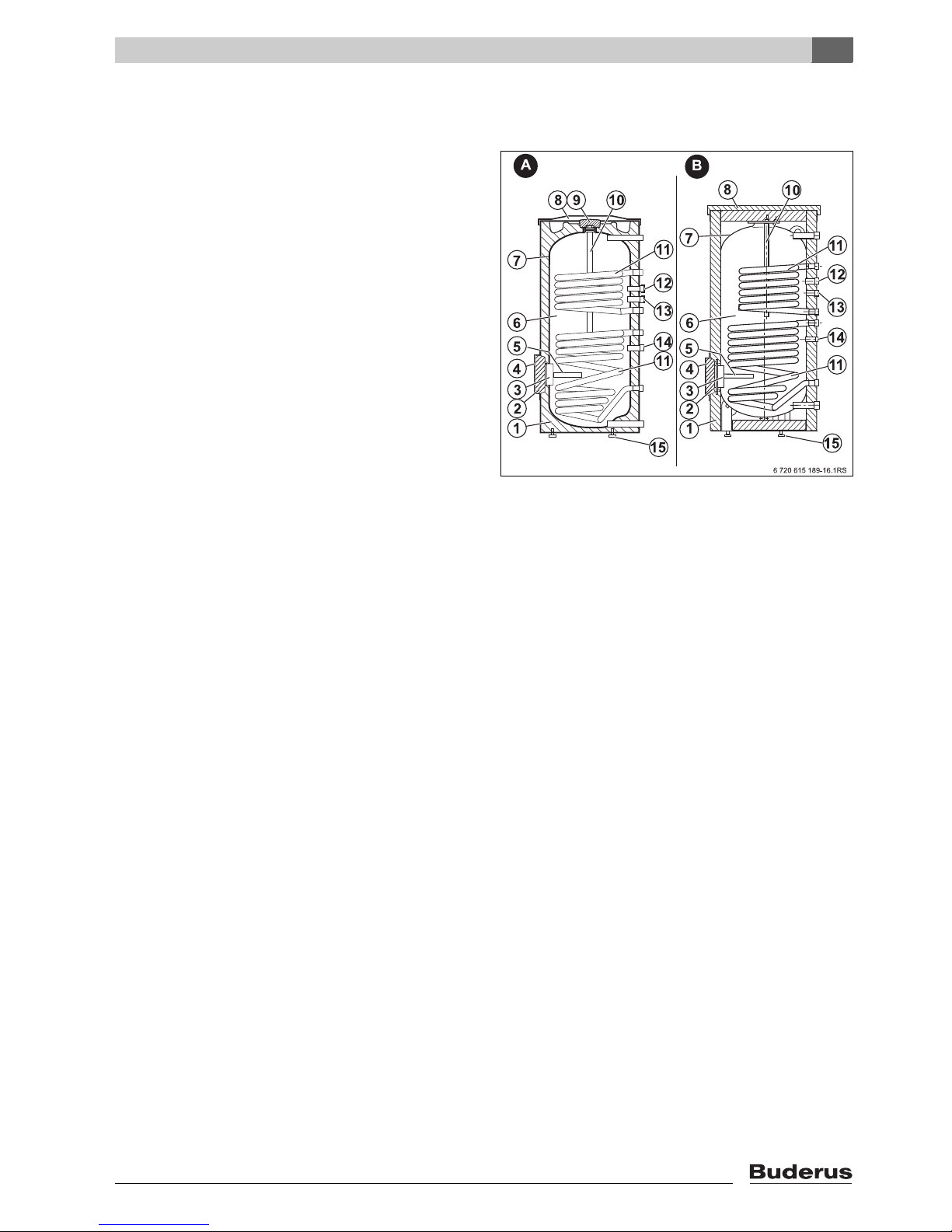
Fig. 1 A: SM300/1
B: SM400/1
1 Insulation
2 Clean-out cover insulation
3 Inspection opening
4 Inspection opening cover
5 Magnesium anode rod
6 Tank shell
7 Thermoglaze Duo Clean
8 Top tank cover
9 Insulation disc for SM300/1 tank
10 Magnesium anode rod
11 Smooth coil heat exchangers
12 Dry well sensing port for heating system control
13 DHW recirculation connection
14 Dry well sensing port for solar
15 Tank feet
2
Logalux SM300/1 - SM400/1 - Technical specifications are subject to change without prior notice.
5
2
Product Description
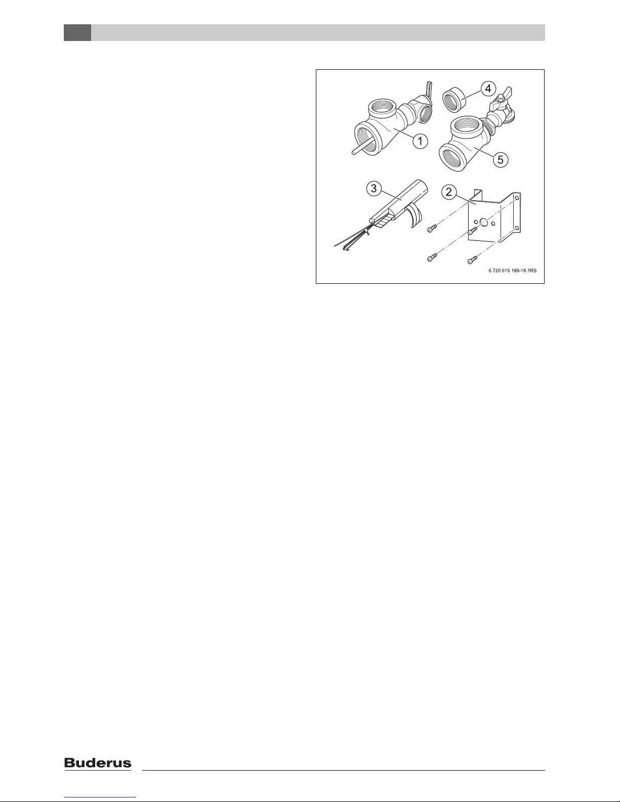
B-Kit Komponenten
Fig. 2 Tank kit fittings
1 Tee piece with P & T relief valve
2 Bracket for mounting of aquastat
3 Spacer set for securing DHW tank sensor
4 Cover cap for DHW recirc connection (EZ)
5 Tee piece with tank drain valve
6
Logalux SM300/1 - SM400/1 - Technical specifications are subject to change without prior notice.
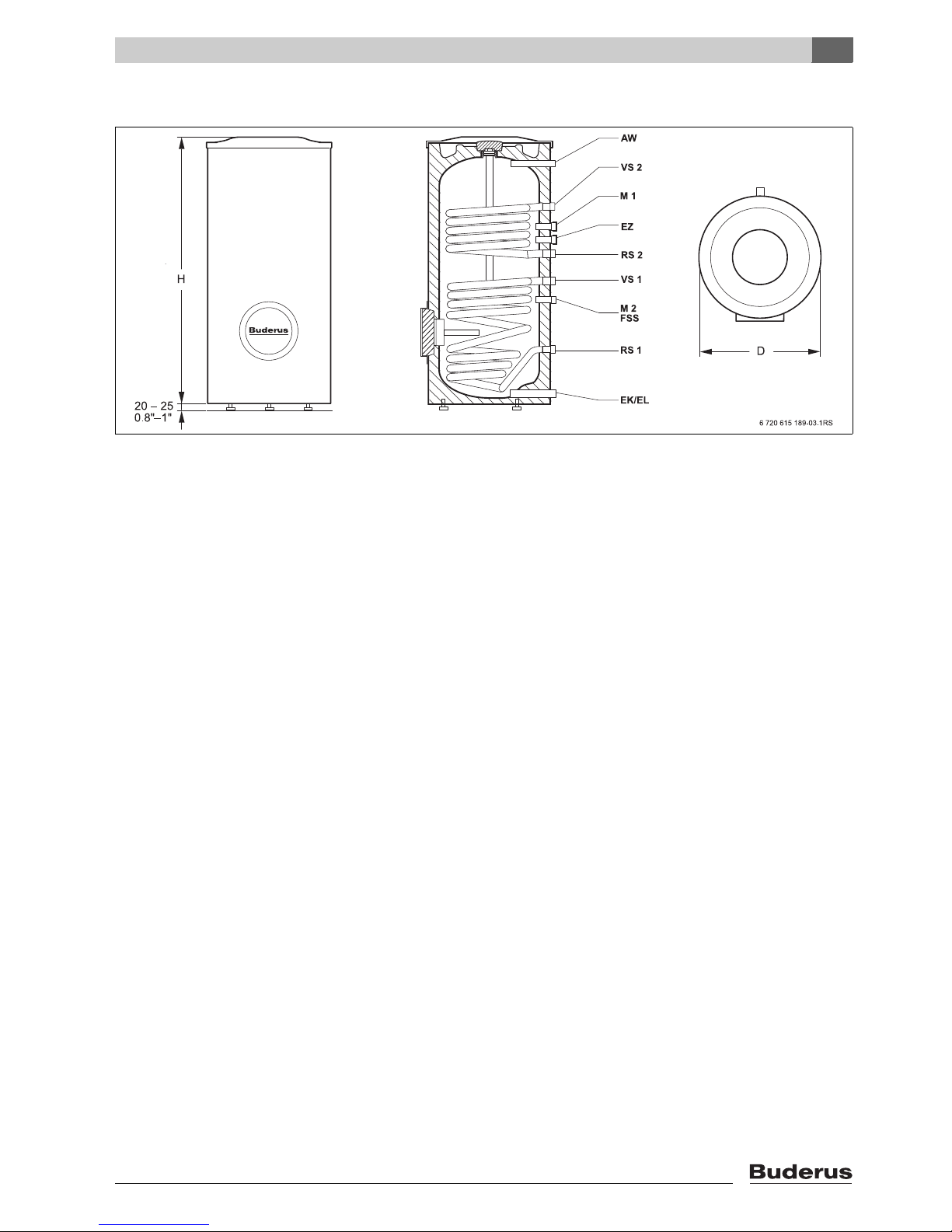
2.6 Dimensions and Connections
Fig. 3 SM300/1 Dimensions and connections
AW DHW outlet
VS1 Solar coil supply
VS2 Boiler coil supply
RS1 Solar coil return
RS2 Boiler coil return
M1 Temperature measuring point for DHW temperature sensor (FB) or aquastat
M2 Temperature measuring point for solar DHW sensor (FSS)
EK Cold water feed
EL Tank drain
EZ DHW recirc tapping
Product Description
2
Logalux SM300/1 - SM400/1 - Technical specifications are subject to change without prior notice.
7
2
4
0.8
Product Description
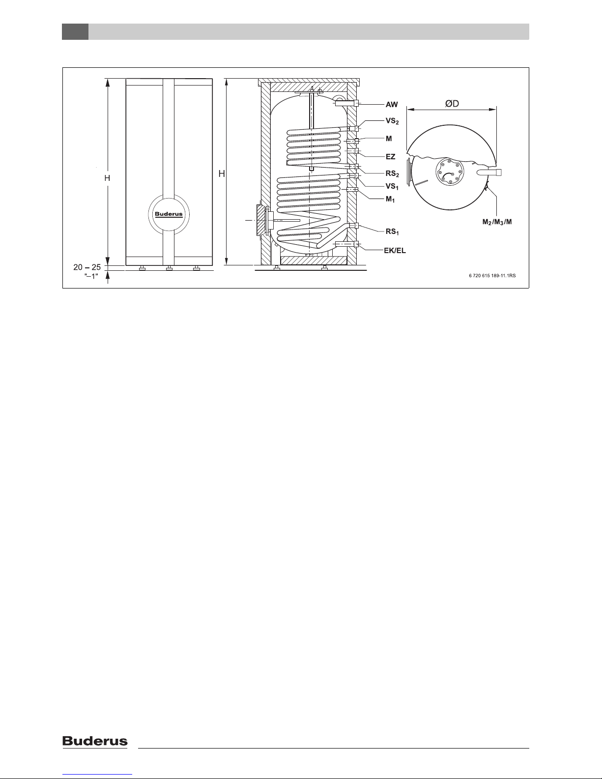
Fig. 4 SM400/1 Dimensions and connections
AW DHW outlet
VS1 Solar coil supply
VS2 Boiler coil supply
RS1 Solar coil return
RS2 Boiler coil return
M Temperature measuring point for DHW temperature sensor (FB) or aquastat
M1 Temperature measuring point #1 for solar DHW sensor (FSS) or temperature sensor solid fuel boiler (FPM)
M2 Alternative location for DHW temperature sensor (FB) or shut-off sensor for loading by solid fuel boiler (FPU)
M3 Solid fuel boiler on temperature
M4 Temperature measuring point #2 for solar DHW sensor (FSS)
EK Cold water feed
EL Tank drain
EZ DHW recirc tapping
8
Logalux SM300/1 - SM400/1 - Technical specifications are subject to change without prior notice.
Product Description
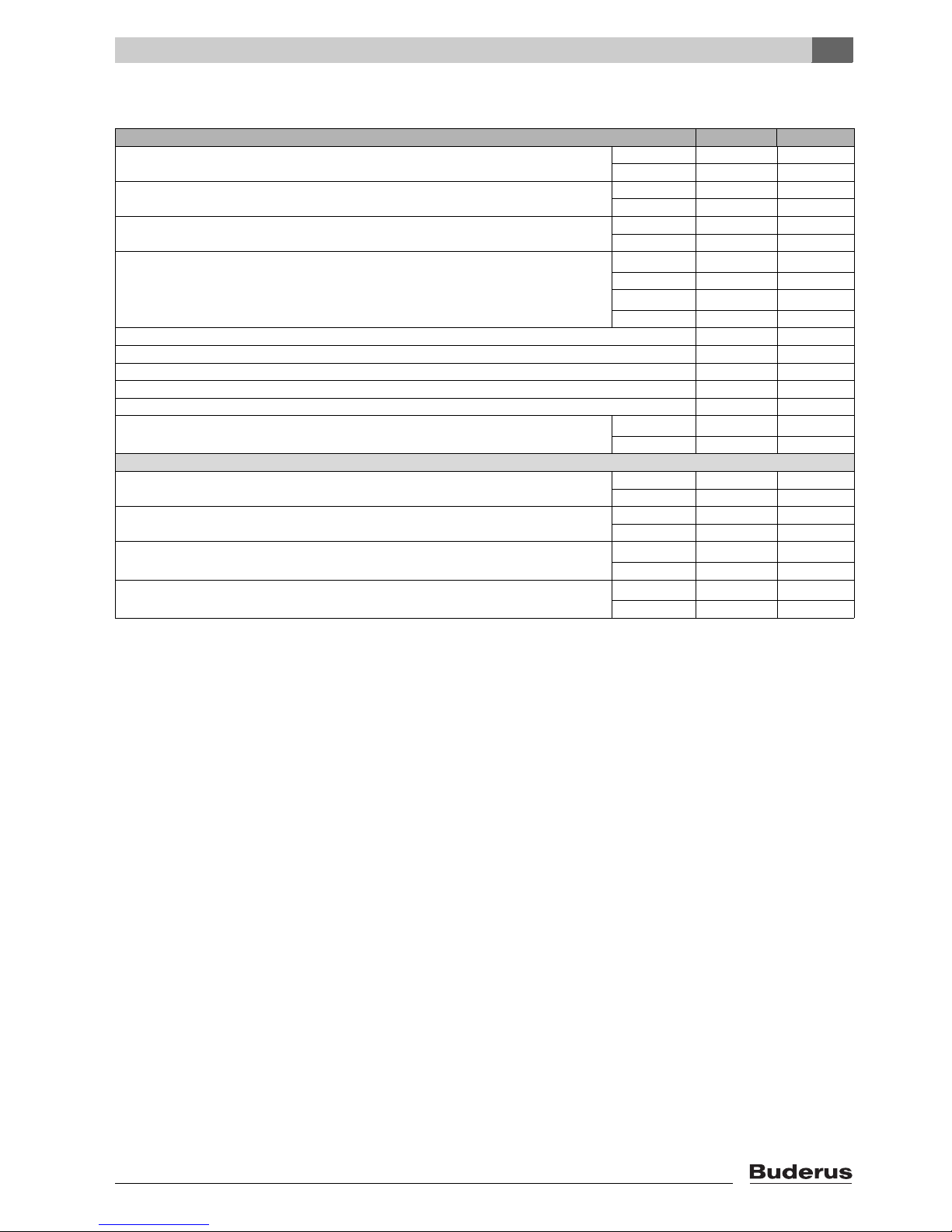
2.7 Technical Specifications
Tank Model SM300/1 SM400/1
Tank volume gal 77 103
Liter 290 390
Volume of solar heat exchanger gal 2 2.5
Liter 8 9.5
Diameter inch 27 34
mm 670 850
1)
Height H
Height H (Installation site)
AW - Domestic outlet connection NPT 1 NPT 1
VS - Coil supply connection NPT 1 NPT 1
RS - Coil return connection NPT 1 NPT 1
EK/EL - tank drain/cold feed NPT 1¼ NPT 1¼
EZ - DHW recirculation connection NPT ¾ NPT ¾
Dry weight
Maximum Operating Values
Solar system fluid temperature °F 320 320
DHW temperature °F 203 203
Operating pressure solar fluid system
Operating pressure DHW
3)
2)
4)
5)
Tab. 1 Technical Specifications
1) Included top cover, without tank feet.
2) Minimum height required for removal of anode rod.
3) Without water, includes packaging.
4) Every installation requires the use of a thermal expansion tank and pressure/temperature relief valve in the heating system and solar system.
5) In the Commonwealth of Massachusetts the operating pressure is limited to 100 psi. Install a 100 psi relief valve.
inch 59 62
mm 1465 1550
inch 86 74
mm 2150 1880
lb. 342 445
kg 155 202
°C 160 160
°C 95 95
psi 232 232
bar 16 16
psi 145 145
bar 10 10
2
Logalux SM300/1 - SM400/1 - Technical specifications are subject to change without prior notice.
9
3
Transportation
3 Transportation
3.1 Transportation Means
One can move the solar water heater tank SM300/1 with
a hand dolly and the SM400/1 also with a lifting crane or
device.
Danger: Potential danger due to falling over
of tank.
V Use only transport devices that are in safe
operating condition
V Place the lifting hook only in the designat-
ed location.
Danger: Potential for injury due to carrying
of heavy loads.
V Also move and lift the tank with at least
two people.
Caution: Potential damage due to improper
securing of tank for transport.
V Use suitable tools and strapping materials
when securing and moving the tank with a
transport aid.
Bring in the entire tank in its original packaging to the final installation location. This will
protect the tank better during transport.
A Buderus dolly (kuli cart) can be purchased
through your local wholesaler.
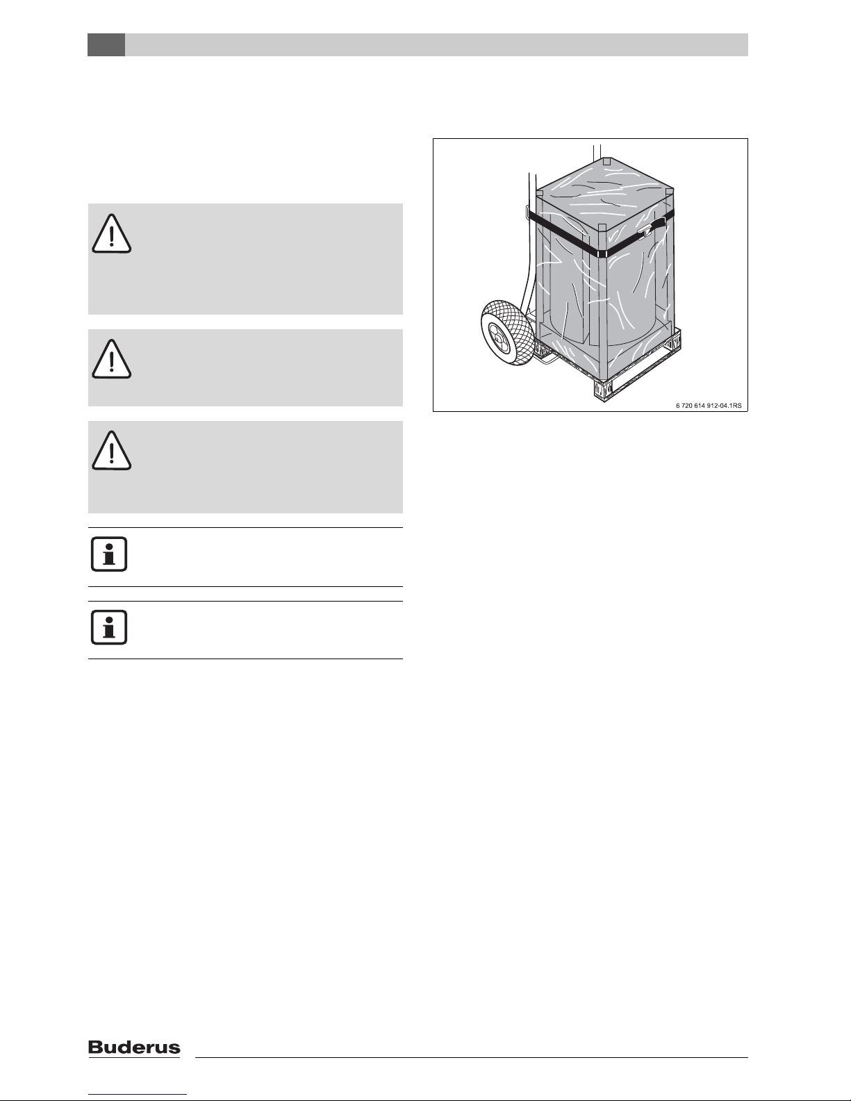
3.1.1 Transportation with dolly
V Place the hand dolly at the backside of the packaged
tank.
V Strap the tank to the hand dolly.
V Move the tank to its final location.
V Remove only the tank packaging at the final installation
site.
Fig. 5 Transportation with kuli cart
10
Logalux SM300/1 - SM400/1 - Technical specifications are subject to change without prior notice.
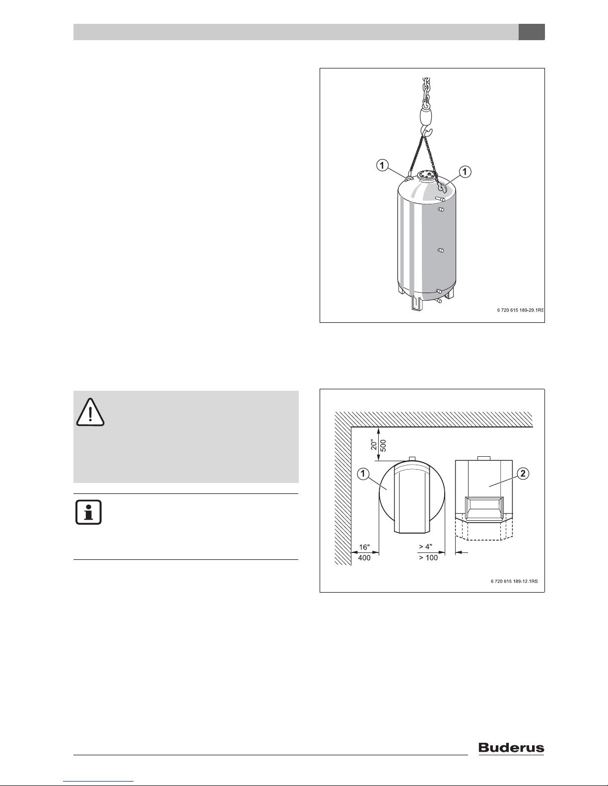
3.1.2 Transportation with overhead crane
V Place the two lifting hooks of the chain into the desig-
nated lifting rings on top of the tank [1].
V Hook the crane chain into the lifting chain.
V Protect the tank from falling and lift the tank to its final
installation location.
V Lower the tank carefully to the floor; do not drop down
onto the floor!
One can move the tank inside the building also in a horizontal manner due to possible height restrictions.
V Remove only the tank packaging at the final installation
site.
Transportation
3
3.2 Product Placement
Caution: Damage due to internal stresses
and corrosion!
V Place the tank in a frost free room.
V Use the solar water heater ONLY in
closed loop applications.
V Open expansion tanks can NOT be used
with these solar water heater tanks.
Minimum 12" overhead space is required for
the removal of the magnesium anode rod as
well as some side clearance.
V Verify for suitable clearance dimensions by
referencing (Æ Tab. 1, page 9 und Fig. 7).
V Maintain suggested service access dimensions
(Æ Fig. 7).
V Maintain 2" clearance from heated pipes to
combustible surfaces.
V Place tank on a level and sufficiently strong floor.
V Remove plastic and packaging materials.
Fig. 6 Transportation with lifting crane (SM400/1)
1 Lifting eyes
Clearance to wall
Fig. 7 Recommended minimum clearances
(in inch/mm)
1 Solar hot water heater
2 Boiler
Logalux SM300/1 - SM400/1 - Technical specifications are subject to change without prior notice.
11
4
Tank Assembly
4 Tank Assembly
4.1 SM300/1 Placement and Installation
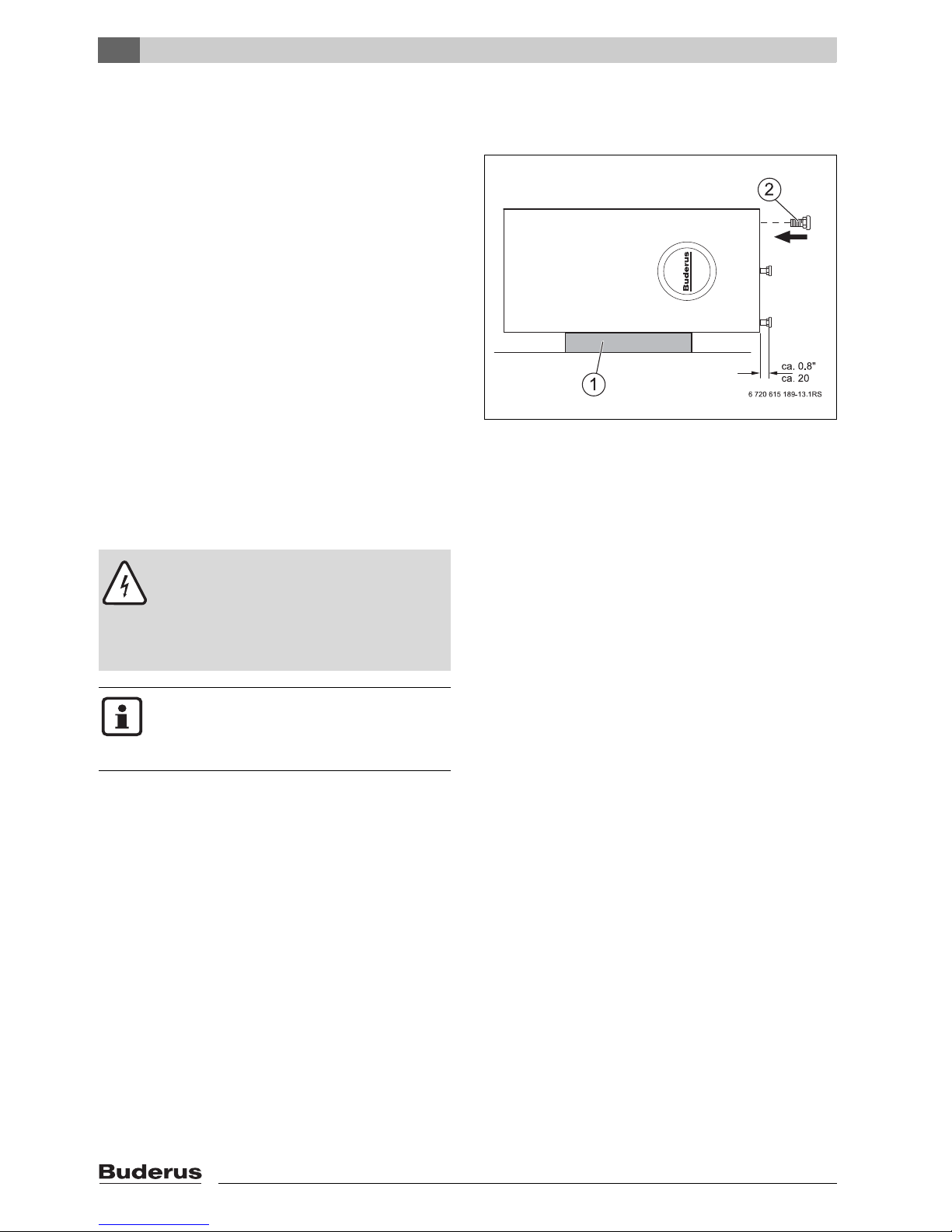
4.1.1 Installation of tank feet
V Place top foam material on the floor [1].
V Carefully place the solar tank on its side on top of the
foam material.
V Remove the tank support bolts M10x30 from the Styro-
foam packaging and screw into the bottom of the tank
[2].
V Put solar tank straight-up and level by adjusting the
tank bolts [2].
Fig. 8 Installation of tank bolts
1 Foam packaging material
2 Tank bolts
4.1.2 Installation of tank aquastat or temperature
sensor
Danger: Risk of fatal injury from electric
shock.
V Electrically disconnect the system.
For DHW temperature control, one can
use an aquastat or tank sensor depending
on the selected control strategy.
Follow the directions supplied by the manufacturer of the aquastat or tank sensor regarding electrical wiring connections and
temperature adjustments.
V To measure and secure the DHW water temperature
an installed temperature sensor or aquastat on the
DHW tank is reqiured.
12
Logalux SM300/1 - SM400/1 - Technical specifications are subject to change without prior notice.
 Loading...