

Buderus Logalux PL750, Logalux PL750 2 S Installation And Maintenance Instruction
Installation and Maintenance
Instruction
Solar Combi-Tank
for DHW and Space
Heating
NOTICE TO HOME OWNER/END
USER OF EQUIPMENT
When the anode rod is not professionally and annually maintained, the
tank will lose its warranty.
Annual service records must be maintained and shown in case of a warranty claim along with an original proof
of purchase.
Refer to page 21 to 25 for annual
maintenance instructions to maintain
tank warranty.
In the Commonwealth of Massachusetts this tank must be installed by a
licensed plumber.
Logalux PL750/2 S
6 720 615 217-00.1RS
Documentation for the
contractor
Please read carefully prior
to installation and maintenance
6 720 615 191 - 08/2008 US

Table of Contents
Table of Contents
1 Safety Precautions and symbol clarification 3
1.1 Safety Precautions 3
1.2 Symbol Clarification 3
2 Product Description 4
2.1 Applications 4
2.2 Intended Use 4
2.3 Guidelines for Installations 4
2.4 Product Disposal 4
2.5 Product Packaging 5
2.6 Dimensions and Connections 6
2.7 Technical Specifications 7
2.8 Glossary of measuring points 8
3 Transportation 9
3.1 Transportation Means 9
3.1.1 Transportation with dolly 9
3.1.2 Transportation with overhead crane 10
3.2 Product Placement 10
4Tank Assembly 11
4.1 PL750/2S Placement and
Installation 11
4.1.1 Installation of tank feet 11
4.1.2 Installation of tank temperature sensor at
MB2 Measuring Point 11
4.1.3 Installation of tank temperature sensor
for boiler control at MB1 measuring point 12
4.1.4 Installation of tank temperature sensors
M1 – M8 12
4.1.5 Installation of tank kit components 13
4.2 Installation of the Insulation 14
4.3 Water Side Piping Connections 15
4.4 Connections for the KS Solar Pump Station 17
7 Replacement Parts 26
7.1 Replacement parts for PL750/2S 26
7.2 Heat Exchanger 27
7.3 Clean-out cover and anode rod assembly for
PL750/2S 29
7.4 Insulation Jacket for PL750/2S Tank 31
5 Start-up and Shut-down of Tank 18
5.1 Start-up Operations 18
5.1.1 Operational information from contractor 18
5.1.2 System start-up 19
5.2 Decommissioning of the system 19
5.2.1 Shutdown of solar hot water tank 19
5.2.2 Shutdown of heating system in cold
weather conditions 19
5.2.3 Environmental protection 20
6 Maintenance 21
6.1 Preparation of cleaning of solar combi-tank 21
6.2 Cleaning of solar combi- tank 22
6.3 Checking of magnesium anode rod 23
6.4 Replacement of Magnesium Anode Rod 24
6.5 Placing solar tank back in operation after
cleaning 25
2
Logalux PL750/2 S - Changes may be made following technical improvements!

Safety Precautions and symbol clarification
1 Safety Precautions and symbol clarification
1
1.1 Safety Precautions
Placement, remodeling
V Fire danger!
Solder and welding operations can result in fire, as the
insulation is combustible.
V The solar combi-tank can only be installed or renovated
by trained installers.
Installation and Start-up Procedure
V Carefully follow these installation instructions, to
ensure long and trouble-free operation.
V Do not assemble the equipment in a damp environ-
ment.
Function
V Follow these directions for trouble free operation,
installation and maintenance.
V Scalding danger!
WARNING! Danger of scalding (> 140 °F) from hot
water. A thermostatic tempering valve must be installed
on domestic hot outlet connection of tank, which is supplied with the KS Solar Pump Station.
Maintenance
V Recommendation for end customer: Please sign
up for an annual service and maintenance contract with
your installer. Make sure to have annual maintenance
performed on your boiler and solar system.
V Use only original Buderus replacement parts.
1.2 Symbol Clarification
Safety warnings are designated in the text
with a triangular warning label and grey coloring.
Signal words are describing the gravity of each danger
when safety precautions are not followed.
– Caution indicates possibility of light property damage.
– Warning indicates light personal injury or severe prop-
erty damage.
– Danger indicates possible severe personal injury with
potential loss of life.
Guidelines in the text are designated with
shown symbol. The text is bracketed between
two horizontal lines.
Guidelines contain important information in order to avoid
or reduce danger to people and equipment.
If the solar storage tank will be installed in Massachusetts,
it must be installed by an a licensed plumber, installer or
dealer who is registered in that state.
We reserve the right to change and improve
technical information without prior notice.
It is expected that the installer is a licensed
heating contractor with the knowledge of accepted industry practices for the installation
and maintenance of the equipment and various applications of the equipment involved.
Logalux PL750/2 S - Changes may be made following technical improvements!
3
2
Product Description
2 Product Description
2.1 Applications
The solar combi-tank PL750/2S is designed for the heating and storage of domestic hot water. Applicable guidelines for domestic hot water must be followed.
2.2 Intended Use
The solar combi-tank PL750/2S is intended for heating
domestic hot water using a closed solar system filled with
a heat transfer fluid to prevent accidental freezing. The
tank can only be used in a closed system.
Any other use voids the warranty of the tank.
2.3 Guidelines for Installations
Follow all specific state and local codes regarding the installation and operation of the
equipment.
All electrical components must be approved
for the US.
2.4 Product Disposal
V Dispose of packaging of the solar tank in an environ-
mental friendly fashion.
V A Solar Combi-tank that is being replaced, must be dis-
posed of in a suitable fashion.
4
Logalux PL750/2 S - Changes may be made following technical improvements!
2.5 Product Packaging
Solar combi- tank PL750/2S consists of:
– Tank shell with corrosion protection
– The cathodic corrosion protection consists of hygienic
Buderus Thermoglaze DuoClean and a magnesium
anode protection system.
– Tank insulation made from non FCKW insulation mate-
rial.
– Solar indirect coil integrated into a heating lance
– Dry well for installation of DHW tank temperature sen-
sor.
– DHW temperature control of the boiler system controls
the DHW temperature.
– Dry well for installation of tank temperature sensor.
– Solar controller regulates the solar system by monitor-
ing the tank and collector temperature sensors.
– Hand-hole cover for service and maintenance access.
– Magnesium anodes.
– Insulation Jacket cover
Product Description
2
5
6
4
3
2
7
8
1
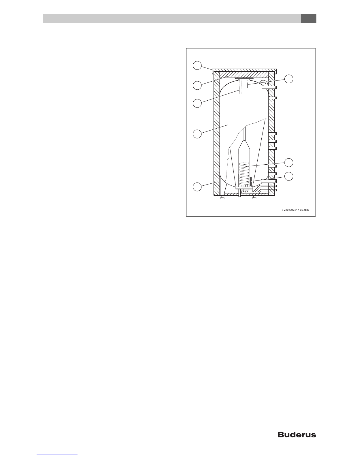
Fig. 1 PL750/2 S
1 Insulation
2 Tank shell
3 Magnesium anode rod
4 Top tank insulation
5 Top tank cover
6 Dry well sensing port (MB1) for boiler control (FB)
7 Stainless steel heating coil
8 Dry well sensing port (MB2) for solar control (FSS)
Logalux PL750/2 S - Changes may be made following technical improvements!
5
2
Product Description
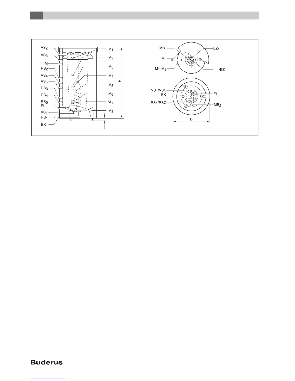
2.6 Dimensions and Connections
AW
AW
0,8"
Fig. 3 Dimensions and Connections PL750/2 S
AW DHW outlet
EK Cold water feed
EZ DHW recirc tapping
RS1 Return tank (Solar)
RS2 Return tank
(Oil, Gas, Condensing boiler for DHW heating)
RS3 Return boiler
RS4 Return heating circuit
RS5 Return solid fuel boiler
RSO Return solar loop
VS1 Supply solar loop
VS2 Supply solid fuel boiler
VS3 Supply tank
(Oil, Gas, condensing boiler for DHW heating)
VS4 Supply tank (heating circuits)
VS5 Supply boiler
VSO Supply solar loop
EL Drain buffer water tank
EL1 Drain DHW tank
M Sensoring port, e.g. Temperature control
M1-8 Used sensoring ports according to system design and
used items
MB1 FB sensor port for measuring actual DHW temperature
MB2 FSS sensor port for solar sensor tank bottom
6 720 615 217-04.1RS
6
Logalux PL750/2 S - Changes may be made following technical improvements!
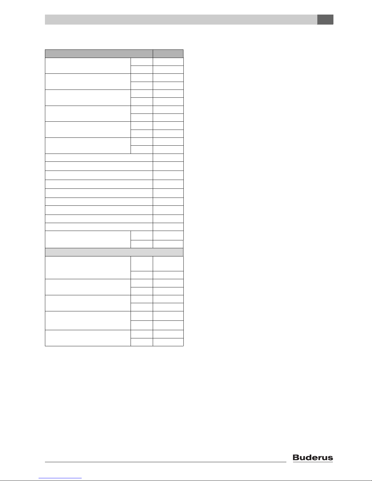
2.7 Technical Specifications
Tank model PL750/2 S
Tank volume total gal 198
l 750
Tank volume DHW gal 79
l 300
Tank volume Buffer gal 119
l 450
Diameter D inch 39
mm 1000
Diameter D (without insulation) inch 31.5
mm 800
Height H inch 76
mm 1920
AW NPT ¾ "
VS
1
RS
1
-VS
VS
2
5
-RS
RS
2
5
EL NPT 1¼ "
EL
1
EK NPT 1 "
EZ NPT ¾ "
Dry weight
1)
lb. 573
kg 260
Maximum Operating Values:
Temperature Buffer water /solar
°F 230
loop
°C 110
DHW temperature °F 203
°C 95
Operating pressure solar loop psi 116
bar 8
Operating pressure DHW psi
bar
Operating pressure buffer water psi 43.5
bar 3
Tab. 1 Technical Specifications
1) Dry weight, incl. packaging material.
2) In the Commonwealth of Massachusetts the operating pressure
is limited to 100 psi. Install a 100 psi relief valve.
3) Every installation requires the use of a thermal expansion tank
and pressure/temperature relief valve in the heating system and
solar system.
NPT ¾ "
NPT ¾ "
NPT 1¼ "
NPT 1¼ "
NPT ¾ "
2)
147
3)
10
Product Description
2
Logalux PL750/2 S - Changes may be made following technical improvements!
7
2
Product Description
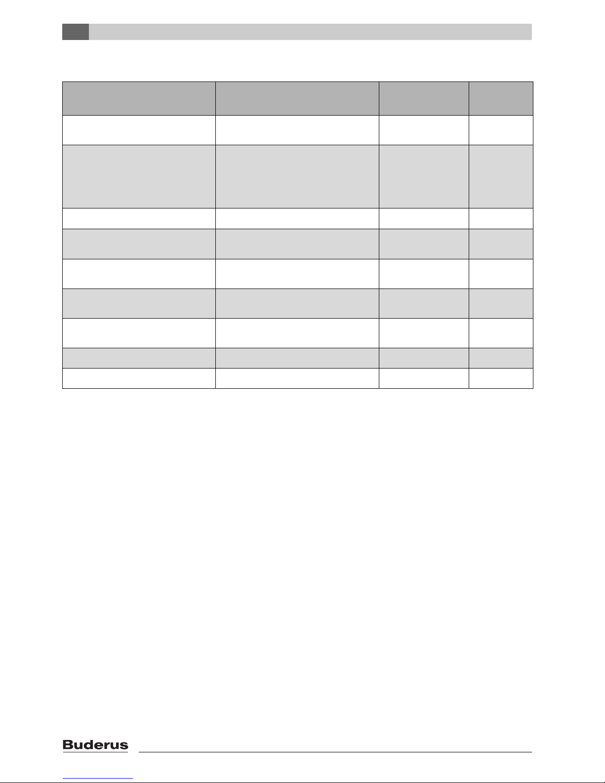
2.8 Glossary of measuring points
Control Type Function/Task Sensor Location
Measuring
Point
With all warm water functions Warm Water Dry Well in Clean-
MB
out Cover
Integrated '-Solar Controls
Switching the solar system on and off Bottom of tank MB
(KS0105/KS0110/KS0120), Logamatic 2107, R43xx
Component '-Solar Controller,
DBS
3rd Party Controller (STECA)
Component '-Flow control of the
PU yes/no
R43xx and Logamatic-Controllers Control of a system test run in combi-
Logamatic 2107, R43xx Heating Control Reference position
Safeguarding max. temperature Top of tank M, M
Bypass PU Reference position
M
for system test run
nation with a hydraulic switch
Reference position
for system test run
M
M
for solar heating
Control for a solid-fuel heating system
Terminate heating of the Solar Combi-
tank
Bottom of tank M
DBS Switch High-flow/Low-flow Middle of tank M
All hot water functions Open selection of functions Bottom of tank M6, M
Tab. 2 Overview sensor ports of PL750/2 S
1
2
1
4
2
5
7
1
8
8
Logalux PL750/2 S - Changes may be made following technical improvements!
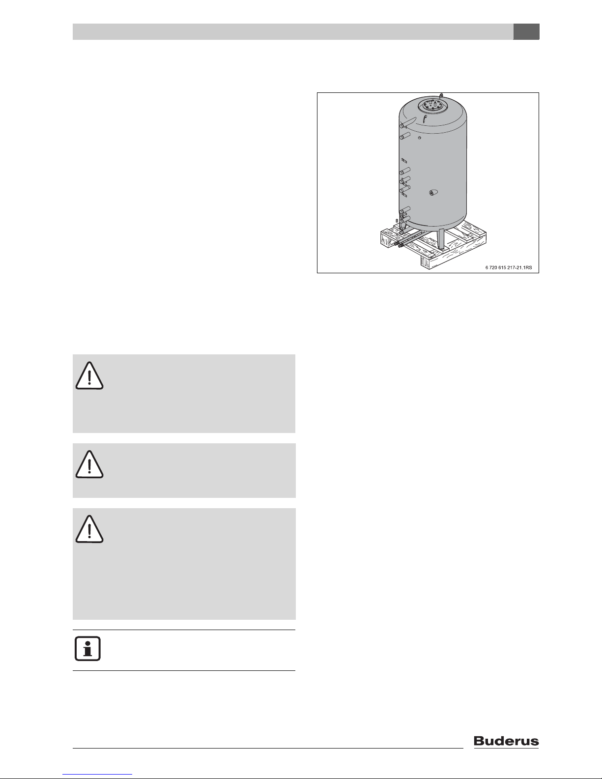
3 Transportation
The solar combi-tank PL750/2S is attached to the pallet
with screws.
Transportation
Fig. 4 Solar combi-tank on pallet
3
3.1 Transportation Means
Move the solar combi-tank PL750/2 S with a hand dolly,
a pallet jack, or a crane.
Danger: Potential danger due to falling over
of tank.
V Use only transport devices that are in safe
operating condition.
V For lifting only attach the harness to the 2
hooks at the top of the tank.
Danger: Potential for injury due to carrying
of heavy loads.
V Also move and lift the tank with at least
two people.
Caution: Potential damage due to improper
securing of tank for transport.
V Use suitable tools and strapping materials
when securing and moving the tank with a
transport aid.
V Bring in the entire tank in its original pack-
aging to the final installation location. This
will protect the tank better during transport.
V Strap the tank to the hand dolly.
V Move the tank to its final location.
A Buderus hand dolly can be purchased
through your local wholesaler.
3.1.1 Transportation with dolly
V Place the hand dolly at the backside of the packaged
tank.
Logalux PL750/2 S - Changes may be made following technical improvements!
9
3
Transportation
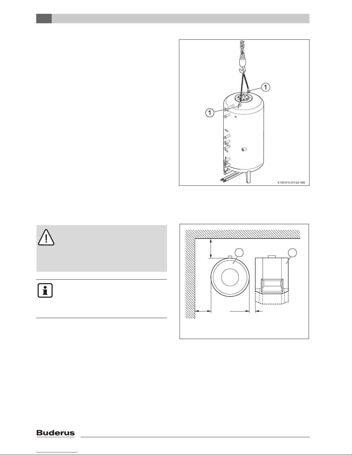
3.1.2 Transportation with overhead crane
V Place the two lifting hooks of the chain into the desig-
nated lifting rings on top of the tank.
V Hook the crane chain into the lifting chain.
V Protect the tank from falling and lift the tank to its final
installation location.
V Lower the tank carefully to the floor; do not drop down
onto the floor!
One can move the tank inside the building also in a horizontal manner due to possible height restrictions.
V Remove only the tank packaging at the final installation
site.
3.2 Product Placement
Caution: Damage due to internal stresses!
V Place the tank in a frost free room.
V Use the solar combi-tank ONLY in closed
loop applications.
V Open expansion tanks can NOT be used
with these solar combi-tanks.
Sufficient overhead space is required for the
removal of the magnesium anode rod as well
as some side clearance.
V Verify for suitable clearance dimensions by
referencing Tab. 1, page 7 and Fig. 6.
V Maintain suggested service access dimensions
(Æ Fig. 6).
V Place tank on a level and sufficiently strong floor.
Fig. 5 Transportation with lifting crane
1 Lifting eyes
Clearance to wall
20"/500
16"/400
1
>4"/>100
6 720 615 217-08.1RS
Fig. 6 Recommended minimum clearances
(in inch/mm)
1 Solar Combi-tank
2 Boiler
2
10
Logalux PL750/2 S - Changes may be made following technical improvements!
4 Tank Assembly
4.1 PL750/2S Placement and
Installation
For easier installation of the solar temperature sensor, install the sensor before you
bring the solar combi-tank up-right
(Æ Section 4.1.2).
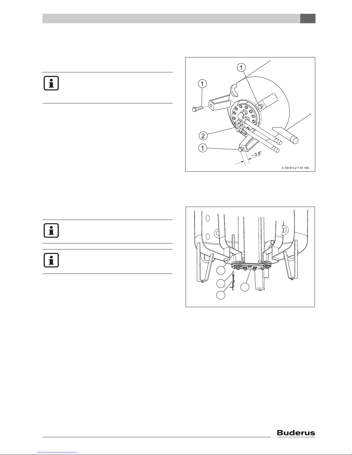
4.1.1 Installation of tank feet
V Carefully lay the tank on its side and remove the feet
screws [1] from the pallet. Discard the pallet.
V Screw the feet screws [1] back into the tank feet
approx. ¾ in (20 mm)
V Check to make sure the drain valve [2] is closed and
the bolts for the hand cover are appropriately fastened.
V Put solar tank straight-up and level by adjusting the
tank bolts.
Fig. 7 Installation of tank bolts
1 Tank feet screws
2 Drain valve
Tank Assembly
4
4.1.2 Installation of tank temperature sensor at
MB
Measuring Point
2
Install the temperature sensor before you install the insulation jacket.
In order to insure the proper function of the
solar control system, install the temperature
sensor in the MB
measuring point.
2
V Insert the solar temperature sensor [2] into the dry well
at the bottom of the tank at loca tion M B
[3] next to the
2
clean-out cover [4]. Push the sensor wire [1] the entire
length of the well until it meets resistance.
3
2
4
1
Fig. 8 Measuring point MB
1 Sensor Wire
2 Solar temperature sensor
3 Measuring point MB
4 Lower clean-out cover
2
6 720 615 217-13.1RS
(solar sensor dry well)
2
Logalux PL750/2 S - Changes may be made following technical improvements!
11
 Loading...