

Page 1
5644258 -
8/95
GB
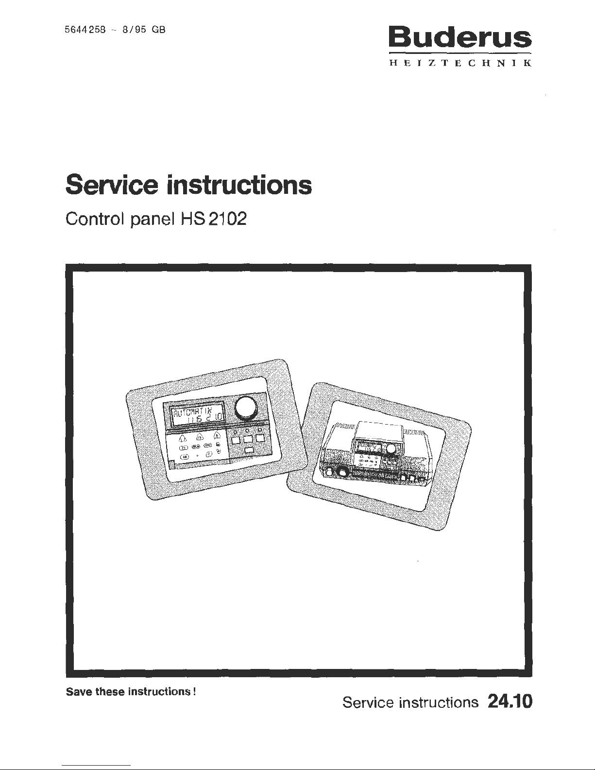
Service instructions
Control panel HS 2102
Save these instructions !
Buderus
HEIZTECHNIK
Service instructions 24.10
Page 2

Attention
The settings described in
this
manual
must
be
performed
by
a qualified heating
company.
All adjustments made which
do
not
correspond
to
the settings and changes described here for-
feit
the warranty.
Switch the current
off
before opening
the
con-
trol
panel (emergency switch outside the heating
room).
2
Page 3
Contents
II
II
El
II
II
II
II
II
II
m
Ill
m
m
Page
Checking the safety temperature limit st
at
. . . . . . . . . . . . . . . . 4
Program overv i
ew
.
5
Key code
.....
6
Installation entries . . . . . . . . . . . . . . . . . . . . . . . . . . . . 7 - 14
Installation entries f
or
special functio ns . . . . . . . . . . . . . . . . . 15 - 17
Re
lay test . . . . . . . . . . . . . . . . . . . . . . . . . . . . . . . .
18
LCD tes
t.
. . . . . . . . . . . . . . . . . . . . . . . . . . . . . . . 19
Heating curve . . . . . . . . . . . . . . . . . . . . . . . . . . . . . .
20
Version
numb
er
. . . . . . . . . . . . . . . . . . . . . . . . . . . . . 21
Re
set . . . . . . . . . . . . . . . . . . . . . . . . . . . . . . . . . .
21
Sensor cur
ve . . . . . . . . . . . . . . . . . . . . . . . . . . . . . . 22, 23
In
dex . . . . . . . . . . . . . . . . . . . . . . . . . . . . . . . . . .
24
Settin
gs
record . . . . . . . . . . . . . . . . . . . . . . . . . . . . . 25
3
Page 4
II
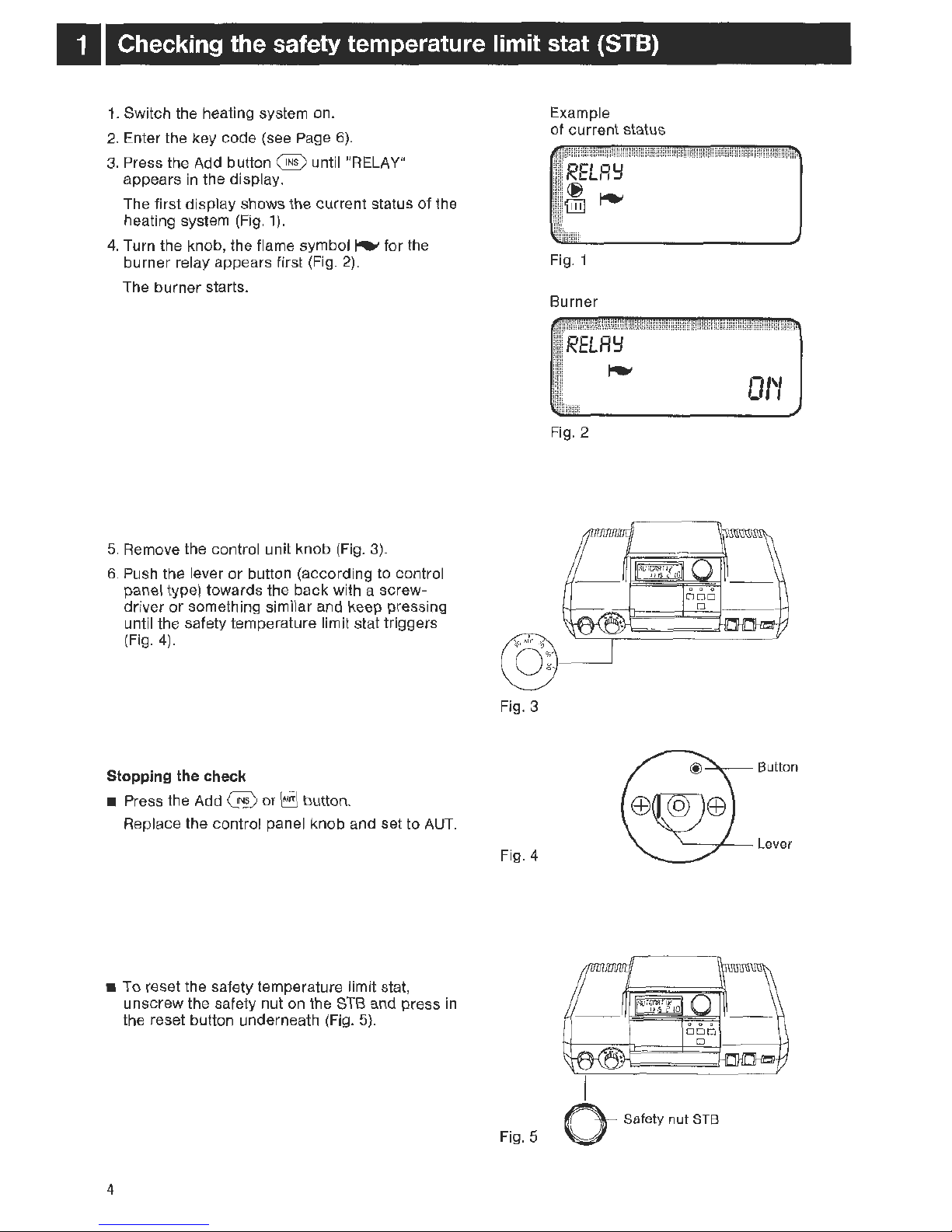
Checking the safety temperature limit stat (STB)
1.
Switch the heating system on.
2.
Enter the key code (see Page
6).
3.
Press the Add
button@
until "RELAY"
appears in the displ
ay.
The first display shows the current status of the
heating system
(Fig.
1).
4.
Turn the knob, the flame symbol ~ for the
burner relay appears first (Fig.
2).
The burner starts.
5.
Remove the control unit knob
(Fi
g.
3).
6.
Push the lever or button (accordi
ng
to
control
panel type) towards the back with a screwdriver
or
something similar and keep pressing
until the safety temperature limit stat
tr
iggers
(
Fig.
4).
Stopping the check
• Press the Add @ or
EJ
button.
Replace
th
e contro l panel knob and set to
AUT.
• To reset the safety temperature limit stat,
unscrew the safety nut
on the
STB
and press
in
the reset button underneath
(Fig.
5).
4
Fig. 3
Fig. 4
Fig. 5
Example
of current stat us
RELR':I
~
'iilll~
Fig. 1
Burner
RELR':I
~
Fig.
2
0 Safety
nut
STB
0/'/
Page 5
Program overview
Possible settings for the 2nd
operating level
1.
Selecting the language
- Factory setting: German
Other languages: French, Italian,
Turki
sh, Polish, Czech
2. Selecting the unit of temperature
- Factory setting:
oc
Possible selection: °Fahrenheit
3.
Nominal setting for heating circuit =
Boiler water temperature .
- Factory setting: 75 °C
4.
Frost protection temperature
- Factory setting: + 1 °C
5.
Remote contro l ON/OFF
- Factory setting:
OFF.
6.
Compensation temperature
(only wi
th
remote control)
- Factory setting: + 3
oc
7.
Setba
ck
mode: Outdoor control
Reduced
Room control (only
with remote control)
Switch-off
- Factory setting: Outdoor control
8.
Minimum switch-on burner temperature
- Factory setting: 10°C
9.
Maximum switch-off burner temperature
- Factory setting: 85°C
10. Flue gas = specificati
on
of a flue gas
temperature
- Factory setting:
OFF
11. Clock = recalibration
- Factory setting: 0 sec
I day
12. Offset = room temperature display
comparison
- Factory setting: 0.0°C
13. Relay test
14.
LCD
test
15. Heating curve
16. Version number
FJ
5
Page 6
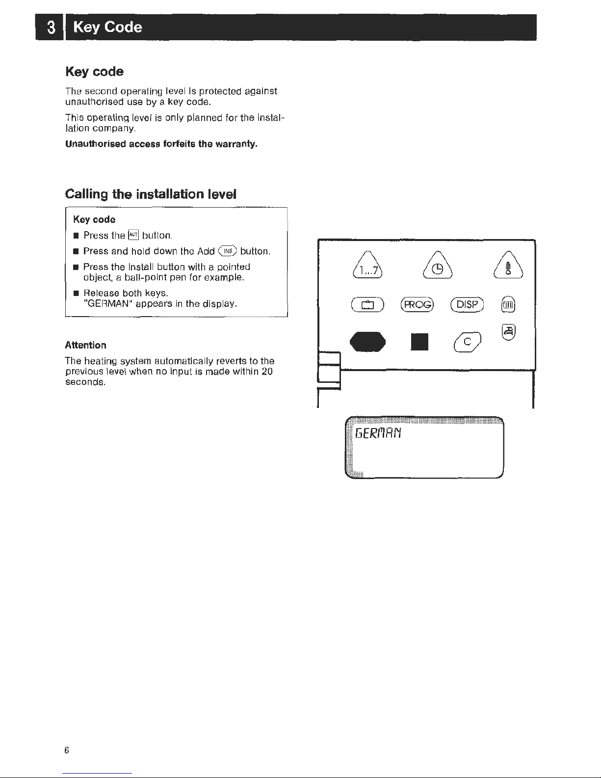
II
Key Code
Key code
The second operating level is protected against
unauthorised use by a key code.
This operating level is only planned for the instal-
lation company.
Unauthorised access forfeits the warranty.
Calling the installation level
Key code
• Press the
§]
button.
• Press and hold down the Add @ button.
• Press the Install button with a pointed
object, a ball-point pen for examp l
e.
• Release both keys.
"GERMAN" a
ppears
in the display.
Attention
The heating system automatically reverts to the
previous level when no input is made within 20
seconds.
6
II
@
Page 7
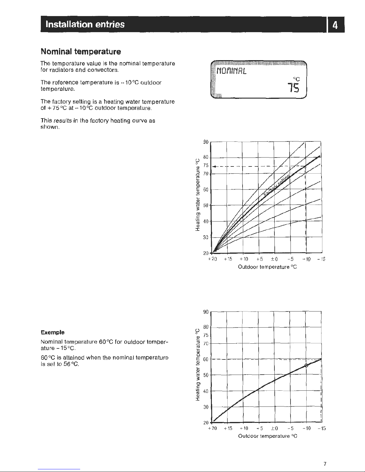
I
Installation entries
Nominal temperature
The temperature value is the nominal temperature
for radiators and
co
nvectors.
Th
e reference temperature is
-10
°C outdoor
temperature.
The factory setting is a heating water temperature
of+
75°C at -10°C
outdoor temperature.
This results in the factory heating curve as
shown.
Example
Nominal temperature 60 °C for outdoor temper-
atu
re
-15°
C.
60
°C is attained when the nominal temperature
is set to 56
°C.
f'
fOI"'trtR
L
oc
15
~
80~
--+---4-
--~
---r--~--
~~
~
Q)
75 ---
...
2
70~
--+---4---~--
~~~~~
~~
I.U
...
Q)
a.
E
60~
--+---4---~-T.
~~~
--
~~
~
$
...
~
50
+-
--4-
--~~~~~~-+~
~~~
Ol
c:
~ 40+---47~~
~~~-+--
-t
~~
=-~
Q)
I
20~--4---~--~--~---+--~--~
+
20
+ 15 +
10
+ 5 ± 0 - 5 -
10
-15
Outdoor temperature °C
90
(.)
80
0
75
Q)
...
::::1
70
-
I.U
...
Q)
a.
E
60
Q)
-
...
Q)
-
50
I.U
==
Ol
c:
~
40
Q)
I
30
--
v
?,
I
v
I
/
I
I
/
I
/
I
1/
I
I
I
20
+20 +15
+10
+5
± 0
-5
- 10 -15
Outdoor temperature oc
7
II
Page 8
II
Installation entries
Changing the nominal temperature
The nominal temperature can be set from
+50
oc
to +90°C.
The heating curve changes relative to changes
in
the nominal temperature.
The factory setting i
s+ 75°C.
• Enter the key cod
e.
• Press the Add @ button until "NOMINAL"
appears
in
the display.
• Turn the knob until the desired nominal
temperature appears.
Automatic operation is automatically res
um
ed
after 20 seconds.
Input range
I Nominal temperature 50°C
-9
0°C
8
rt0/'11/~RL
oc
15
N 0
1'111'1
R L
oc
56
Factory setting
Own
entry
75°C
Page 9
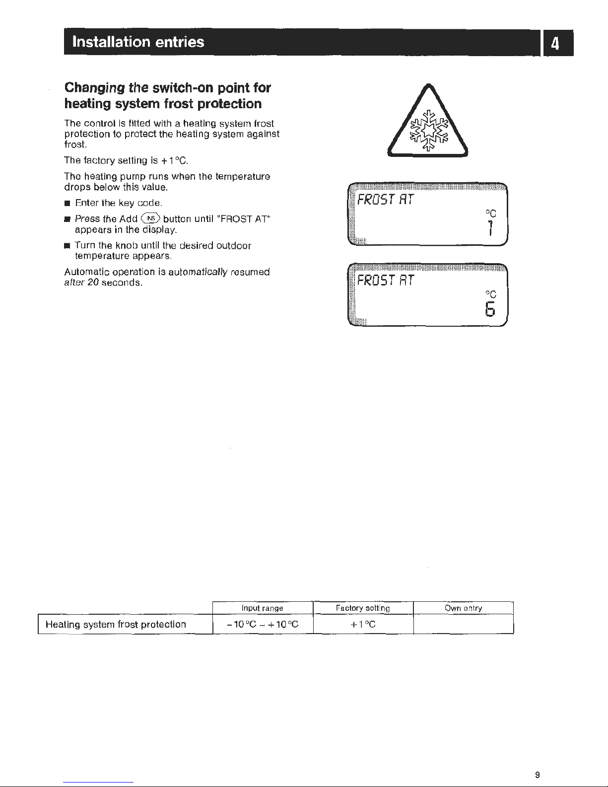
Installation entries
Changing
the
switch-on
point
for
heating
system
frost
protection
The control is fitted wi
th
a heating system frost
protection to protect the heating system against
fros
t.
The factory setti
ng
is + 1 °C.
The heating purnp runs when the temperatur e
drops below this value.
• Enter the key code.
• Press the Add @ button until "FROST
AT
"
appears
in
the displa
y.
• Turn the knob until the desired outdoor
temperature appears.
Automatic operation is
au
tomatically resumed
after 20 second
s.
Input range
I Heating system frost protection - 1 0 °C - + 1 0 °C
•
FROST
RT
oc
6
Factory setting Own entry
+ 1°C
9
Page 10

•
Installation entries
Remote control Yes I No
The remote control must be activated when the
control is fitted with a
BFC
remote control.
• Enter the key code.
• Press the Add
@ button until "REMCONT
OFF" appears in the display.
• Turn the knob until
,.ON"
appear
s.
Automatic operati
on
Is automatica lly resum
ed
after 20 second
s.
Once the remote control has been activ ated, it is
no longer possible
to adjust the pl
an
day and
night temperatures
on
the control panel; they can
o
nl
y be adjusted using the remote control.
"REMCONT" a,ppears in
th
e display when the
Temp button
m is pressed.
I Remote
co
ntrol
10
Inpu t range
OFF/O
N
REI'ICOI'IT
REI'ICOI~T
Factory setting
OFF
-cr:
o,
,-
01'1
Own entry
Page 11

Installation entries
Compensation temperature
The compensation temperature can only be
entered after the remote
co
ntrol has been
activated. The compensation temperature limits
the influence of the room temperature on the
heating water temperature
(h
eating curve).
The factory setting
is
3 °C.
Attention: The influence of the room temperature
on the heating wat
er
temperature (heating curve)
is not active when you enter "OFF
".
• Enter the key code.
• Press the Add
@ button until "COM
PEN
SAT"
appears
in
the display.
• Turn the knob until
,.
OFF"
or
th e des ired com-
pensation temperature appears.
Automatic operation is automatically resumed
after 20 seconds.
Input range
I Compensation temperature
OFF
I 1 - 10°C
•
COI'IPENSRT
oc
ll!iillll!l
3
COI'IPEriSRT
OFF
Factory setting Own entry
3°C
11
Page 12

II
Installation entries
Setback mode
You can choose between tour setback modes:
1.
Outdoor control (factory settin
g)
2. Reduced
3.
Switch-off
4.
Room contro l (only wi
th
remote control)
Sel
ect
ing
the se
tba
ck
mod
e
Outdoor
control:
Reduced:
Swi
tc
h-off:
Rom
control:
Either switch-off or r
ed
uced mode
is set dependi
ng
on the outdoor
temperatur
e.
The threshold is the frost protection temperatur
e.
Adjustment to a lower pl
an
room
temperature . The heating circuit
ci
rc
ulati
on
pump con tinues to run.
Th
e heating circuit
is
completely
switched-off, apart from fr ost pro tection, during setback time
s.
The room t
el"!)pe
rature set with
slide switch
(S,
is maintained.
You can only select the room con trol setback mode when a remote
control is available and ,
REM
-
CO
NT
ON" has been set under
"Remote
co
ntrol
Yes/No".
• Recommended settings:
Heating circuit with
remote contro
l:
Heating circuit without
re
mote con tro
l:
Floor heating:
Heating circuit sw
it
ched oft
for setback:
• Enter the key code.
Room control
Outdoor
co
ntrol
R
ed
uced
Switch-off
•
Pr
ess the Add @ button until "OUTDOOR"
appears
in
the display.
• Turn the knob until the desired setba
ck
mode
appears.
Automatic ope ration Is automati
ca
lly resumed
after 20 seconds.
Input range
Setback mode Outdoor, Reduced,
Switch-off, Room
12
OUTDOOR
REDUCED
SI.JITCH-OFF
Factory setting
Own e
nt
ry
Ou
tdoor
Page 13

Installation entries
Minimum switch-on temperature
This is the boiler temperature at which the burner
is switched
on
at the latest when
heati
ng
is
required.
The
factory setting is 10
°C.
• Enter the key code.
• Press the Add @ button until
"M
IN
ON"
appears in the displ
ay.
• Tu
rn
the knob until the desired minimum
switch-
on
temperature appears.
Automatic operation is automatically resum
ed
after 20 seconds.
Input range
J Min. switch
-o
n temp. 10
°C-40°C
Minimum switch-off temperature
This is the heating water temperature at which the
burner is switched off at the earliest.
The factory setting is 45
°C.
Th
is value cannot
be
set at the installation level
and is not shown in the disp l
ay.
II
!lili!!ill§i!~
!:~~;~§
~lgj~~;HIIWii!tsa::Ei~
lflEEE
~ii!iltii
l;
f'l/1
'/ 0 /'/
oc
10
oc
20
Fa
ctory setting Own entry
10
°C
13
Page 14

I
Installation entries
Maximum switch-off temperature
Th
is is the nominal temperature whi ch should not
be exceeded
in
the boiler.
The factory setting is
85 °
C.
• Enter the key code.
• Press the
Add@
button until "MAX
OFF"
ap
pears in the display.
• Turn the knob until the desired maximum
switch-off temperature appea r
s.
Automatic operation is automatically resumed
after 20 seconds.
I
Max.
switch-off temp.
14
Input range
65°C-
90°C
f'lRX
01'
1
oc
85
llilililll
l
f'lRX
OFF
oc
15
Factory setting
Own entry
85°C
Page 15

Installation entries for special functions
Flue gas
The flue gas temperature can only be measured
wi
th the additional module
KM
202 and a flue gas
sensor.
A service message
is
output using the
ECO-KOM
modem (when installed) when the flue gas
temperature set is exceeded.
The boiler must then be serviced.
The factory setting is
OFF.
Flue gas measuring must be activated when the
additional module and the fl
ue
gas sensor are
installed.
• Enter the key code.
• Press the Add @ button until "FLUE GAS"
appears in the display.
• Turn the knob until the desired maximum flue
gas temperature appears.
Automatic operation is automatically resumed
after 20 seconds.
The flue gas temperatur
e,
and all other
temperatures, can be inquired using the
display on the operating level.
Input range
I Flue gas temperature
OFF
I
50°C-
250°C
FLUE
GAS
FLUE
GAS
Facto
ry
setting
OFF
0
.-.
,-,-
oc
785
Own entry
15
Page 16

El
Installation entries for special functions
Clock
You
can set the clock to a second.
The factory setting is 0 seconds/day.
Determine the deviation.
• Enter the key code.
• Press the Add @ button until "CLOCK"
appears
in
the disp lay.
• Turn the knob until the determined deviati
on
appears
in
the display.
For exampl
e,
set
-10
sec/day when the clock
runs 1 0
sec/
day too fast.
Automatic operati
on
is automatically resumed
after 20 seconds.
Input range
I Cl
ock
-
59
to +
59
sec/
day
16
CLOCK
0
I
H!illlll
'
CLOCK
-10
Factory setting Own entry
0
Page 17

Installation entries for special functions
Offset
"OFFSET" can be used for adjustments when the
nominal room temperature shown in the display
deviates from the actual room temperature
measured with a thermometer.
The factory setting
is
0.0°C.
For exampl
e,
displayed nominal room
temperature 22
oc
actual room temperature 24 °C
• Enter the key code.
• Press the Add @ button until "OFFSET"
appears in the displ
ay.
• Turn the knob until - 2.0°C appears in the
display.
Automatic operation is automatical
ly
resumed
after 20 second
s.
Input range
I Offset
-5.0°C-
+5.0
°C
OFFSET
oc
0.0
OFFSET
oc
-2
.0
Factory setting Own entry
0.0°C
17
Page 18

I
Relay test
You
can use the relay test to test the switch
relays
in
the control pan
el.
The following relays
can be called up:
- burner
- domestic water loading pump
- heating circuit circu lation pump.
• Enter the key code.
• Press the
Add@
button until "RELAY"
appears in the displ
ay.
The actual heating system status is shown
in
the first display.
• Turn the knob. The flame symbol
~
for the
burner appears firs
t.
"RELAY ON" is sent
to
the control panel when
the burner function is correct.
"ON" does not appear when a malfunction is
detected.
• Turn the knob furth
er.
The symbols for
domestic water and heating cir
cuit
circu lation
pump relays appear sequentially.
The pump function can be checked when the
pump symbo l appears in the displ
ay.
The relay test has no time limit.
Stopping or leaving the relay test:
• Press the Add @ or
§]
button.
18
An
example of the actual heating
system status.
i!
iiii!H
H
Burner
RELAY
~
Domestic water
01'1
Heating circuit circul ation pump
RELAY
~
'iilll
Page 19

LCD test
You can use the
LCD
test to check whether a
ll
digits and symbols are shown correctly in the
display.
• Enter the key code.
• Press the
Add@
button until "LCD-TEST"
appears
in
the display.
• Turn the knob. All digits and symbols must
appear correctly
in
the display.
The display is defective
wh
en it is not complete.
The unit must th
en
be replaced.
All other displays under "LCD-TEST" are for inter-
nal factory use only.
Automatic operation is automatically resumed
after 20 seconds.
LCD-
TEST
I I I
III [(I
OJ
JJJ
III
CO
Ill
ITI
$
185
''"'I'M~'
~ll.l.l
00 lXI
~I ~I
0
f°C
~~~
.---
@)~e.:
oc1.0D£
_I
Lf
Ll
1234567 OLf"CICJ pm
Ll
LI.O
I
19
Page 20

El
Heating curve
You ca n u
se
the heating curve test to display the
heating water temperature for the nominal day
room temperature which is effective for outdoor
te
mp
eratures of
+10
°C,
± 0°C and - 10°C.
•
En
ter the key code.
• Press the
Add@
button until
"HE
ATCURV
E"
appears
in
the display .
• Turn the knob.
The
first display shows the
heating water temperature for +
10°C,
the
second for ± 0
°C
and the third for - 10°
C.
Automatic operation is automatically resumed
after 20 seconds.
20
HERTCURIJE
oc
Y7
10
HERTCURf)E
oc
S6 0
HERTCURIJE
oc
66 - 7 0
Page 21

Version
number
The
version number is a key number and represents the manufactured status of the control
panel.
The
version number must
be
specifi
ed
for recla-
mations or control panel
ex
tensions.
• Enter the key code.
• Press the Add @ button until
"VERS
ION"
appears in the di
splay.
Automatic operation is automatically resumed
after 20 seconds.
RESET
RESET
• Press and hold down the
Time~
.
Add @
an
d Cance l @ buttons at the same
time until
"RESET" appears in
th
e displ
ay.
• Hold all three buttons down until a
ll
digits/
characters have disappeared from the display.
RESET
sets a
ll settings back to the factory
settings, language to
GER
MAN
and unit of
temperature to
°C.
Switching points,
time and day of the week
remain set.
VERS/0
1'1
706
Ll
I
Version
number~
RESET
Factory set version number
o@
8888
888
21
Page 22

m
Sensor curves
Ge
neral
Switch
off
the current before measuring.
Measure the resistance at the
cab
le ends.
Outdoor temperature sens
or
80
""
60
a
~
~
'
~
(\)
0
The comparative temperature (room, flow, outdoor
and flue gas temperatures) must be measu-
red close to the sensor.
The
cur
ves show mean values and are subject
to
tolerances.
c
11:1
40
~
"""
Ui
·w
(\)
a:
~
r---.-.
20
~
r-----._
-
0
- 15
- 10
- 5 ± 0
+5
+1
0
+1
5
Out
door
temperature (
0
C}
Boiler, flow, warm water temperature sensors
14
12
10
a
~
8
(\)
0
c
11:1
-
C/)
6
·w
(\)
a:
4
2
·"'
""
"'
"'
"'
~
"""'
..........
r--.......
r--...
r--
0
20
30
40
50
60 70
80
90
Heating wat
er
temperature (
0
C)
22
Page 23

Sensor curves
Ill
Room temperature sensor
22
20
18
a
~
16
Q)
()
c:
tU
-
C/l
14
'(i)
Q)
a:
12
10
8
""
"
""
"""
"'
......
"'
~
.........
""'
~
~
~
5 10 15 20 25
30
Room temperature (°C)
Flue gas temperature sensor
350
300
250
a
~
200
Q)
()
c:
tU
-
C/l
150
'iii
Q)
a:
100
50
~
\
\
\
~
~
~
~
r---_
0
I
0
20 40
60
80
100
1
20
140
160 180 200
Flue gas temperature (
0
C}
23
Page 24

Index
c
Checking the safety temperature limit stat
C
lock
Compensation temperature
F
Flue
gas
temperature
Frost prot
ect
ion
H
Heating curve
Heating syst
em
frost protection
Heating water temperature
K
Key
code
L
LCD test
N
Nominal temperature
0
Offset
p
Program overview
R
Relay test
Remote co ntrol
24
4
16
11
15
9
20
9
7,8
6
19
7,8
17
5
18
10
s
Saf
ety
temperature limit stat
Sen
sor
curv
es
Setback mod e Outdoor contro l
Reduced
Room control
Switch -off
Switch-off te
mperature,
maximum
Switch
-o
ff temperature, minimum
Switch
-on
temperature
T
Time-switch
v
Version number
4
22
,23
12
14
13
13
16
21
Page 25

Protocollo delle tarature
Operating values on the 1st operating level
Input range
Factory
Own entry
setting
Factory program
1-8,
EMPTY
1 Family
Domestic water
OFF
1 40°C to 60°C
OFF
Domestic water temperature
40°C to 60°C
Summer/winter changeover
10°C
to 30°C
Day room temperature
10°C
to
30°C
Night room temperature
10°C
to 30°C
Operating values on the 2nd operating level
Unit
of
temperature °C I °F
oc
Language German
Nominal temperature
50°C to
90°C
85°C
Heating system frost protection
- 10
oc
to + 1 0
oc
+1 °C
Remote control
OFF I ON
OFF
Compensation temperature
OFF
I 1- 10°C
3°C
Setback mode Outdoor control Outdoor control
Reduced
Room control
Switch-off
Minimum switch-on temperature
10°Cto40°C
10°C
Maximum switch-off temperature
65°C
to
90°C 85°C
Flue gas temperature
OFF
I 50 °C to 250 °C
OFF
Cl
ock
- 59 to
+59
sec/day
0
Offset - 5.0°C
to+
5.0°C 0.0°C
25
Page 26

Page 27

Page 28

Subject
to
change without notice!
 Loading...