

Buderus GB162/80, GB162/100 Submittal Sheet
GB162/80 and GB162/100
Gas Condensing Boiler
• Natural Gas
• Liquid Propane
Engineering
Submittal
Sheet
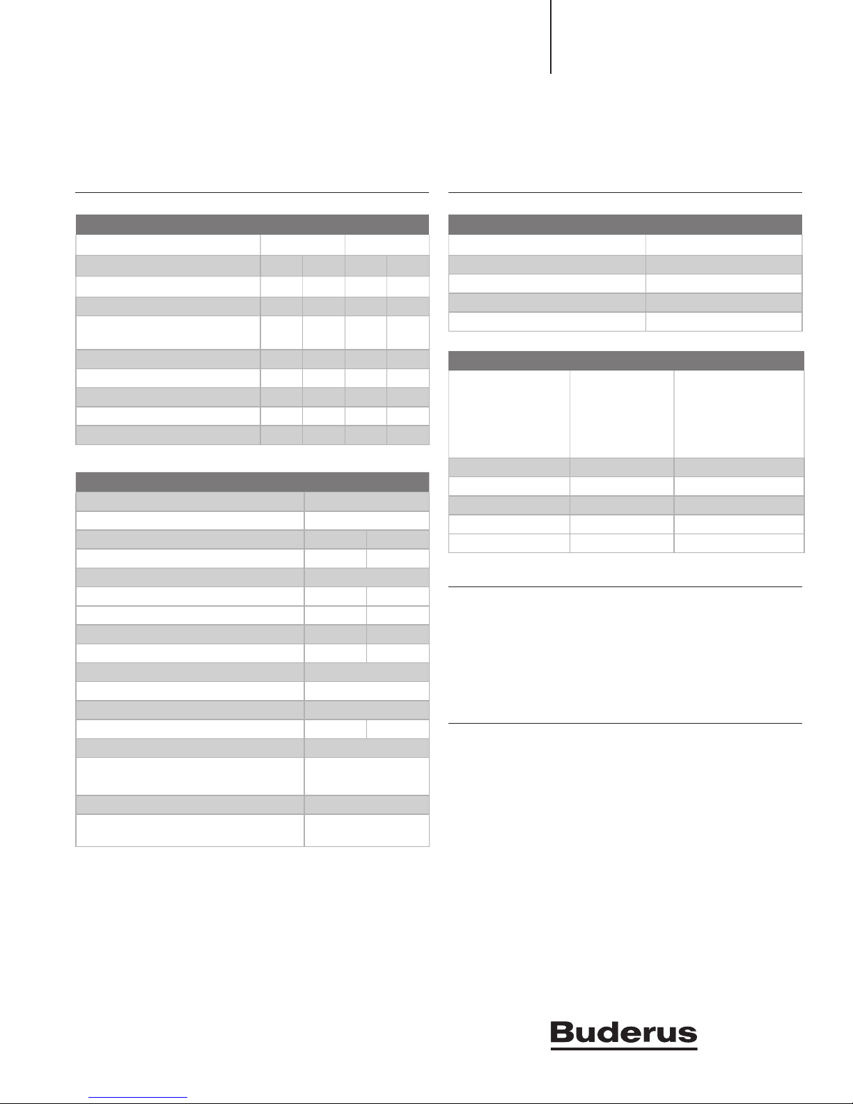
GB162/80 and GB162/100 Performance Data
GB162/80 GB162/100
NG LP NG LP
Gas Input (MBH) 290 270 333 315
Gross IBR Output (MBH) 260 242 298 282
Output at Minimum
Capacity (MBH)
Net IBR Rating (MBH) 226 210 259 245
Thermal Efciency (IBR) — — 90.7 90.7
Combustion Efciency (IBR) — — 90.8 90.8
DOE Steady State (%) 89.7 89.6 — —
AFUE (%) 93.8 93.4 — —
61.4 51.6 61.4 51.6
GB162/80 and GB162/100 Operational Data
Dry Weight (lbs.)- without pump group 154
Approx. Water Content (gal.) 1.3
Min Inlet Gas Pressure ("WC) NG: 3.5 LP: 8.0
Max Inlet Gas Pressure ("WC) NG:10.5 LP: 13.0
Max High Limit Temperature (°F) 200°F
162/80 162/100
Fireside Pressure Drop (Inch WC) .602 .883
Flow Rate at 18°F ∆T (GPM) 30 38
Flow Rate at 36°F ∆T (GPM) 15 19
Max Working Pressure (psi) 50
Relief Valve Rating (MBH) 925
Relief Valve Pressure Rating (psi) 30
Max Supply Temp Heating/DHW (°F) 190 190
Max equivalent exhaust vent length (ft) 100
Max equivalent combustion air
vent length (ft)
Venting Category IV
Approved Venting Materials PVC, CPVC¹ ²,
¹ The following system is approved for use in U.S.A and may be used
with this boiler:
PVC Schedule 40, 80 - ANSI/ASTM D1785
PVC DWV - ANSI/ASTM D2665
CPVC Schedule 40, 80 - ANSI/ASTM F441
Pipe cement primer: PVC -ANSI/ASTM D2564
CPVC -ANSI/ASTM F493
² The following system is approved for use in Canada and may be used
with this boiler:
IPEX - System 636 CPVC (available in 4"only)
BH Gas Venting Systems
100
AL29-4C
GB162/80 and GB162/100 Electrical Specications
Electrical Voltage Mains 120V/60Hz
Electrical Voltage Controls 24V
Power Consumption Max Load 3.0 Amps
Power Consumption Min Load 2.0 Amps
Max Permissible Fuse Rating (A) 5.0 Amps
GB162/80 and GB162/100 Clearances
Minimum
Clearance
to
Combustibles
(Inches)
Front 20 28
Rear (wall mount) — —
Side 0 —
Above 6 6
Flue pipe to wall * 6 6
* To centerline of ue
Wall Clearance
Recommended
(Inches)
Additional Information
• Outdoor reset AM10 standard with outdoor sensor
• DHW priority MC10/BC10 standard (DHW sensor included)
• Modulating premix burner
• Direct-vent sealed combustion
• 30 psi relief valve
Options
• Condensate neutralization tank (NE–0.1)
• Logamatic 4323 Control - BMS interface
- Sequencing up to 8 boilers
- System and zoning control for pumps and valves
- Solar integration
- Plate and frame heat exchanger control
• CM10 two boiler module
• EM10 BMS integration 0-10V input stand alone control
• Low water cutoff
• High temperature manual reset
• RC35 Control
Note: Refer to applications manual for specic information on venting,
piping, electrical connections, and pump sizing.
| GB162/80 and GB162/100 Gas Condensing Boilers |
A(L
A)F
l
u
ega
s c
o
n
n
ect
io
n
;
insidediamet
e
r
4(100m
m
)
B(AA)Airin
t
ake c
o
n
e
cti
o
n
;
insided
amete(00
)
C
(WB
)
W
allBracke
t
otsho
w
n
(VK
)
;
G
½’’
uonu
t
E
(
G
AS)Gas
co
n
ectiontobo
ile
r
;
1
T
female
threa
d
F
(RK
etu
r
;
e
male thead
G
½’’
unionutt
G
K
O)Condensateoutle
t
;
ose
u
p
g
oups
u
p
G
1
½
alethrea
d
,
f
la
t s
eal
I
Gasco
n
n
ecti
onto
shut off valve
1NPTfemal
e t
h
r
ea
d
(
)
J
(PR)
u
p
g
oupretu
;
G
1
½
malethread
,
f
a
t seal
1.4 (3
5
)
5.4
(1
38
)
6.4
(162 mm)
G
/B
(152 mm)
m
(6 mm)
"
(520 mm)
)
m
(6
)
oss
eade
1
(10
)
(
)
”
(
)
(520 mm)
(100
)
)
.6
(1
)
6
(406 mm)
6 m
4
(12
)
d
AAAi
i
id
W
K
;
a
ASn t
ea
D
e s
N
t
e
s
shed
)
oss
eade
Engineering Submittal Sheet
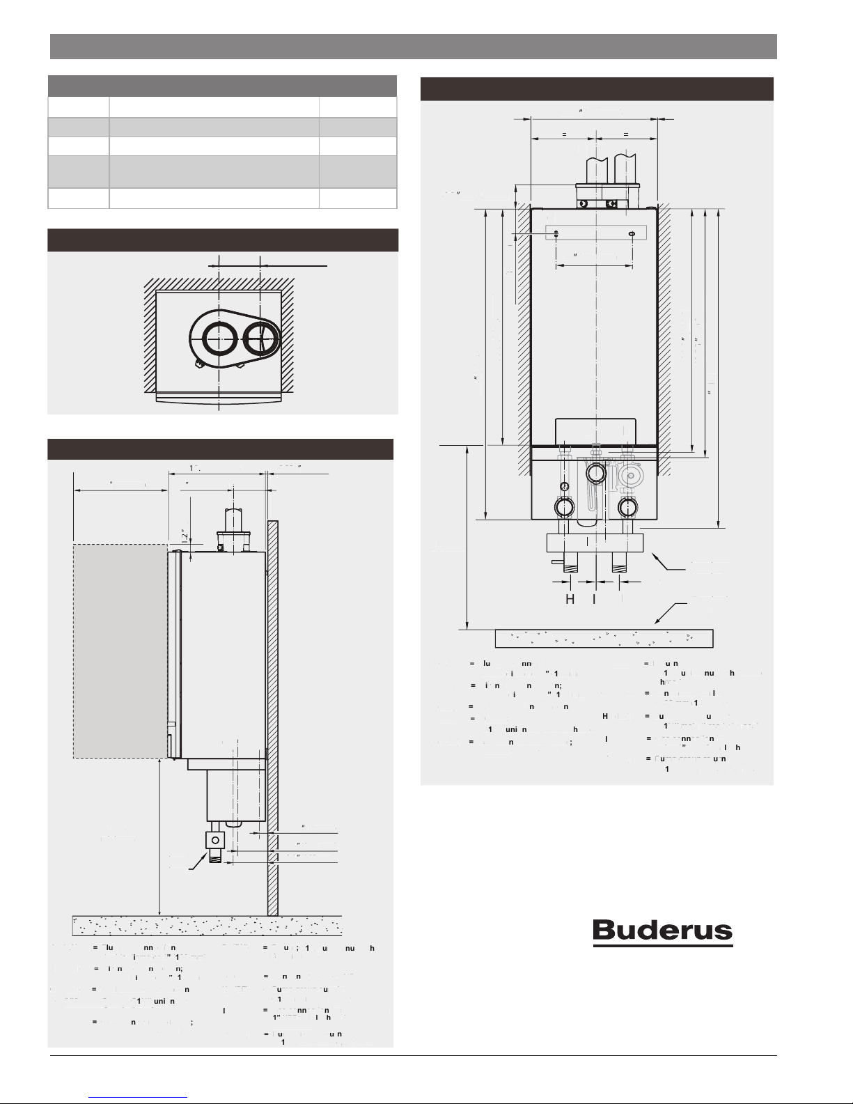
GB162/80/100 Piping Connections / Specications
A (LA) Flue Connection Diameter 4"
B (AA) Combustion Air Pipe Diameter 4"
I (GAS) GAS Connection Size 1" NPT
D (RK)
/F (VK)
Boiler Return & Supply
Connections
1½" NPT
G(AKO) Condensate Connection ¾" hose
GB162/80 and GB162/100 Top View
5.5 ” (140 mm)
GB162/80 and GB162/100 Side View
18. 3” (465 mm) 0.25 ” (6 mm)
20.5"
(520 mm)
.5
(465 m
6” (152 mm)
A/B
A
30 mm
” (30 mm)
.25
GB162/80 and GB162/100 Front View
.5
00 20.5 ” (520 mm)
A B
4.1 ” (10 3.5 mm)
.
5 mm
C
16” (406 mm)
1
D FE
H I
mm
0 mm
55
39.5 ” (100 3 mm)
40,55 ” (10 30 mm)
10 mm
1
51.6 ” (13 10 mm)
F
Low Loss
Low L
Header
H
Finished
ini
oor
r
r
3⅞"3⅞"
J
24.
8”
4.
(6 30 mm)
(63
mm
minimum
minimum
0 mm
.
50.4 ” (12 80 mm)
mm
9
38.5 8” (9 80 mm)
mm
1
. 3
5. 3” (1 35 mm)
D/F
F
G
E
24.
8” (6 30 mm)
4.
3
mm
minimu
minimum
Low
Low
Loss
L
Header
H
r
A (LA) = Flue gas connection;
B (AA) = Air intake connection;
C (WB) = Wall Bracket (not shown)
D (VK) = Supply;
E (GAS) = Gas connection to boiler;
Data subject to change without notice | BTC 432008101 A
inside diameter 4” (100 mm)
inside diameter 4” (100 mm)
=Supply
female thread
female thread
G1½’’ union nut
n
’’ NP
1’’ NPT female thread
n
(n
m
)
H/J
J
)
F (RK) = Return;
G (AKO) = Condensate outlet;
H (P
H (PF) = Pump group supply;
I
J (PR) = Pump group r eturn;
R
female thread
(A
) =
G1½’’ male thread, flat seal
= Gas connection to shut off valve
1” NPT female thread
not shown
(not shown)
G1½’’ male thread, flat seal
1.4 ” ( 35 mm)
mm
5.4 ” (1 38 mm)
mm
6.4 ” (162 mm)
n
G1½’’ union nut with
’’ m
ply;
’’
¾" h
¾" hose
l
A (LA) = Flue gas connection;
A
A
B (AA) = Air intake connection;
WB
C (WB) = Wall Bracket (not shown)
V
D (VK) = Supply;
E (GAS) = Gas connection to boiler;
cct
u
n
(
h
nsi
inside diameter 4” (100 mm)
ns
inside diameter 4” (100 mm)
ll
racke
upply
’’
G1½’’ union nut female thread
’’ maler
1’’ NPT female thread
(
00m)
)
te
(RK)
F (RK) = Return;
)
AK)
G (AKO) = Condensate outlet;
(
H (PF) = Pump group supply;
I
(PR)
J (PR) = Pump group return;
’’n
G1½’’ union nut with female
a
thread
Ø 32 mm (1¼”) O/D
’’
G1½’’ male thread, flat seal
= Gas connection to shut off
valve 1
valve 1” NPT female thread
m
’’
G1½’’ male thread, flat seal
Bosch Thermotechnology Corp.
50 Wentworth Ave
Londonderry, NH 03053
Tel: (603) 552-1100
Fax: (603) 584-1681
www.buderus.net
n
nsau
l
)
r
w
/
ply
o shut off
Buderus
l
 Loading...