

Page 1
SP1
SERIES
INSTRUCTIONS FOR BRYSTON
SP1 PRECISION
PREAMPLIFIER/PROCESSOR
Page 2

For more information, call us today or visit our web site,
1-800-632-8216, www.bryston.ca
Page 3

INTRODUCTION
Congratulations on your purchase of the Bryston SP1
precision pre-amplifier/digital processor-decoder.This product
will provide you with the finest available signal control and
DSP audio processing available. Like all Bryston products the
SP1 has been carefully designed and engineered to deliver a
lifetime of enjoyment.
Because the SP1 offers both pre-amplifier and digital decoding
functions it is very important that you thoroughly read this
manual BEFORE you install and use the SP1.
UNPACKING AND ELECTRICAL SAFETY
Your SP1 was carefully packed at the factory to protect
against any damage in shipping and handling. Carefully
examine the packing and the unit for any signs of external
damage or impact and report those to your dealer or Bryston
prior to using the unit.
ACCESSORIES
In the carton you should have found the following accessories
in addition to the SP1:
The Bryston Safety Manual
1 IEC standard power cord
1 SP1 Infrared Remote Control unit with backlight
1 9V Battery for the remote - must be installed
It is VERY IMPORTANT that you read and completely understand the
Safety Manual before installing or connecting the SP1 to any electrical
power source.
1
Page 4
SP1 FUNCTIONAL LAYOUT
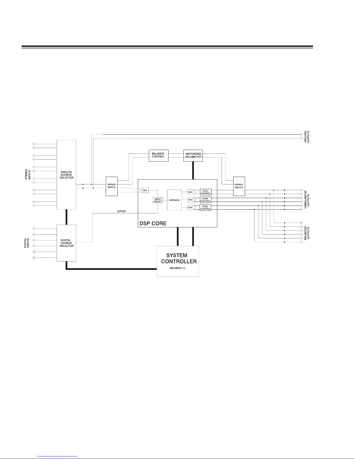
Below is a block diagram of the Bryston SP1. It shows the
signal flow and basic operational structure of the Surround
Processor and Preamplifier.
2
Figure 1: Block Diagram
Page 5
POWER
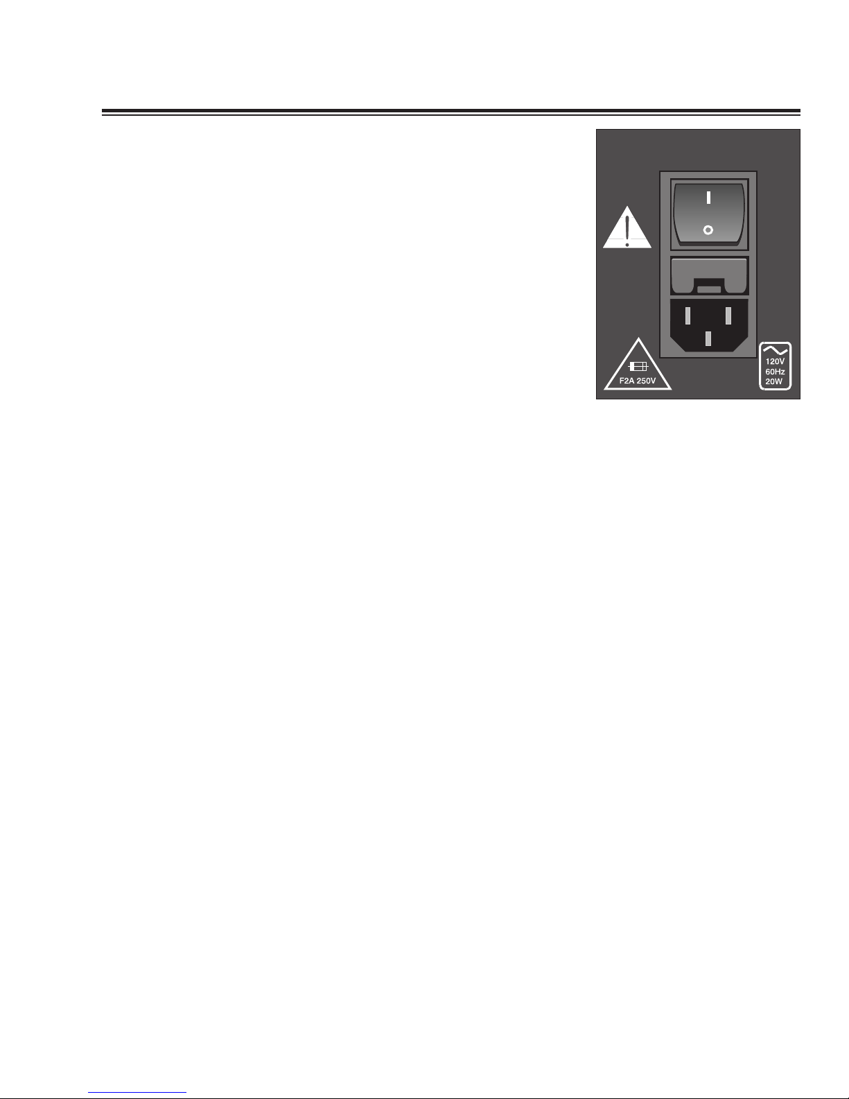
The SP1 uses a dual mode electrical power system. In the
electrical power input module located on the right hand side
of the rear panel, adjacent to the IEC power cord socket is a
large computer-style switch that controls the main electrical
power to the unit.This is the ONLY switch that actually
completely turns off all power to the unit. Please see the
illustration below.
When the SP1 is connected to an appropriate AC power
source, and the power switch is switched to the ‘I’ position,
the unit automatically sets itself into a STANDBY power mode,
where-in only the minimum necessary circuitry to respond to
the remote control's power-on command or the momentary
power toggle switch on the front panel are active.
Activating the momentary POWER toggle switch (either up or
down) on the front panel or the POWER button on the
remote immediately takes the unit out of its STANDBY mode
into its normal operating mode.
The presence of AC power to the SP1 is indicated by the
illumination of the front panel LCD display, the illumination of
the LED corresponding to the source you last selected, and
the unit’s LED operating mode indicators.
[NOTE: If your unit's LCD backlight does not illuminate when the SP1 is
plugged into an operating outlet, and switched out of STANDBY mode,
please check to see that the rear panel main power switch {mains switch}
is in the ON position.]
If the SP1 is to be unused for an extended period of time (i.e.
a vacation) it is strongly recommended that it be turned off
using the main power switch on the back panel.
3
Figure 2 – Power Input
Module
Page 6
4
CONTROLS AND CONNECTIONS - OVERVIEW
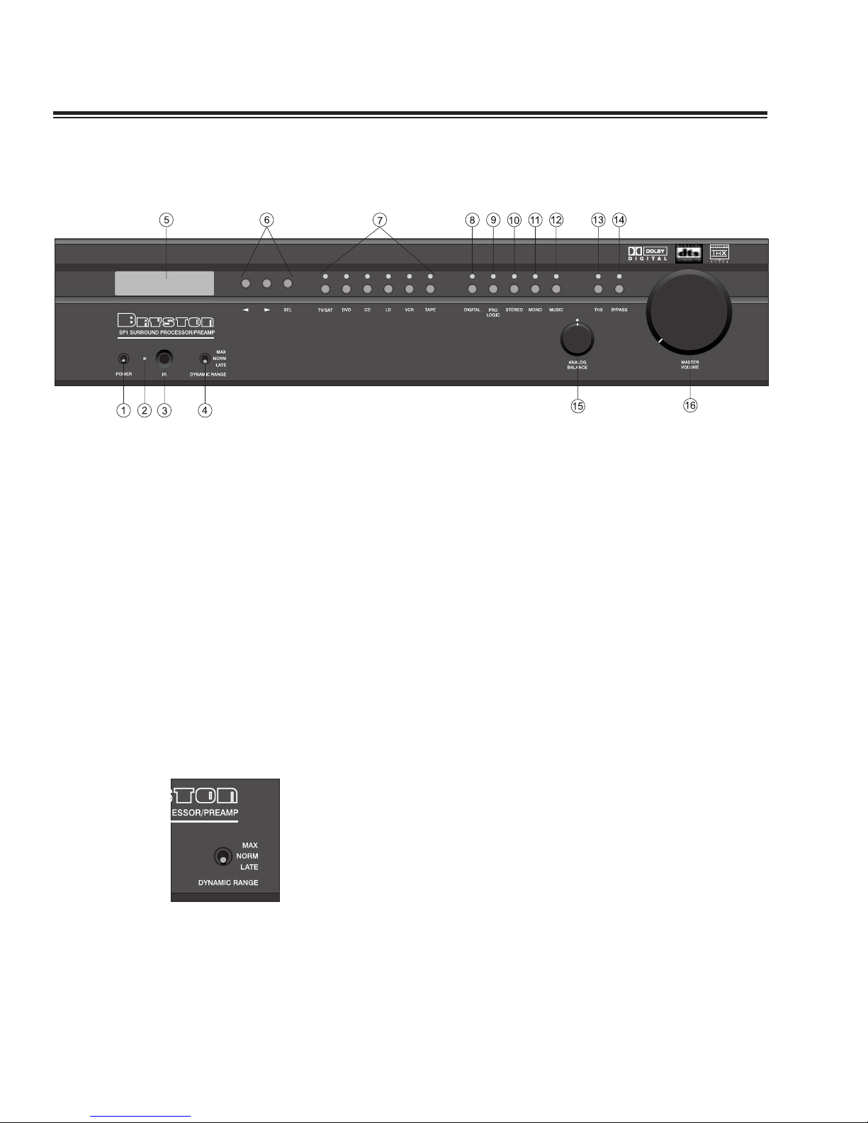
Front Panel Controls and Indicators
When looking at the front panel of the SP1 you will see the
following controls and displays from left to right:
1. Power [Momentary Switch]
Toggling this switch up or down takes the unit in and out of
its' Standby power mode (see above)
2. Standby and (IR) Infrared Activity Indicator
If this LED is continuously bright, it is an indication that the
SP1 is in Standby mode. When the SP1 is powered up, the
LED is OFF, and flashes when a valid IR code is detected.
3. (IR) Infrared Receiver/Sensor for remote control
4. Dynamic Range Control
This three position switch,which will operate only when the
SP1 is in a Dolby Digital mode, permits the adjustment of the
dynamic range (softest sound to loudest sound) of signal
sources producing a Dolby Digital bitstream.
Figure 3: Front Panel
Page 7

A brief explanation follows:
There are two variables built into many Dolby Digital
bitstreams during the encoding process by the program
producers, that can enable decoders like the SP1 to provide
automatic gain control based upon the information supplied
by these data variables.
One of these two variables (labeled Dynrng by Dolby)
provides a type of compression useful for situations such as
late night viewing of programs with a wide dynamic range
(like many action movies).This function can also be used to
provide compression for program material that may require
enhancement of overall intelligibility (such as some older
soundtracks).
Another feature provided by this option is the necessary peak
limiting required avoiding signal overload when "downmixing"
functions are selected.
The second variable (labeled Compr by Dolby) provides
additional peak limiting to allow overall average program level
to be increased.
These two algorithms can provide sufficient overall gain
reduction to allow even high dynamic range soundtracks to
maintain good audibility at low volume levels.
In most cases as an integral part of the Dolby Digital encoding
process, a certain minimum amount of dynamic range
reduction will be automatically included in the bitstream to
ensure safe downmixing.The precise amount of this function
is selected by the program producers, and will to a degree
depend on the contents of the audio channels.
5
Page 8
6
USING THE DYNAMIC RANGE CONTROL
For the majority of applications this switch should be placed
and remain in the middle or NORM position.
For late night viewing or at any time you wish to reduce the
overall dynamic range of a program the switch may be set to
the "LATE" (down) position.
If you wish to turn off all of the software's built-in dynamic
range management functions the switch can be set to the
"MAX" (up) position.
NOTE: Caution should be exercised when choosing this option. Many
smaller loudspeaker systems cannot handle the extremely wide range
signals produced in this mode. Overall system volume should be initially
set quite low until you or your dealer are able to determine the maximum
safe setting to avoid damage to your loudspeaker systems or power
amplifiers.
5. LCD Display window - contains the two line, black on
green 16 character per line alphanumeric display which
indicates the status and functional mode of the SP1.This
screen is also used during the menu-setup function for
calibration of the SP1 to your system.
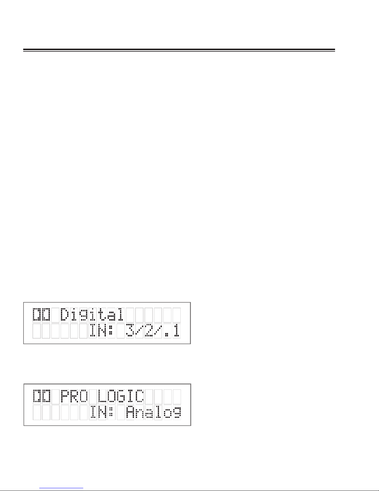
On the first line, the decoding type [Dolby Digital, DTS, ProLogic, Music, etc.] is displayed.A sample screen is shown
below: (FIG 4)
On the second line, the type of signal being detected from the
currently selected input is displayed.A sample screen is
shown below: (Fig 5)
Figure 4: Status display showing Dolby
Digital 5.1 channel signal at input
Figure 5: Status display showing analog
input signal and Pro Logic decoding
Page 9
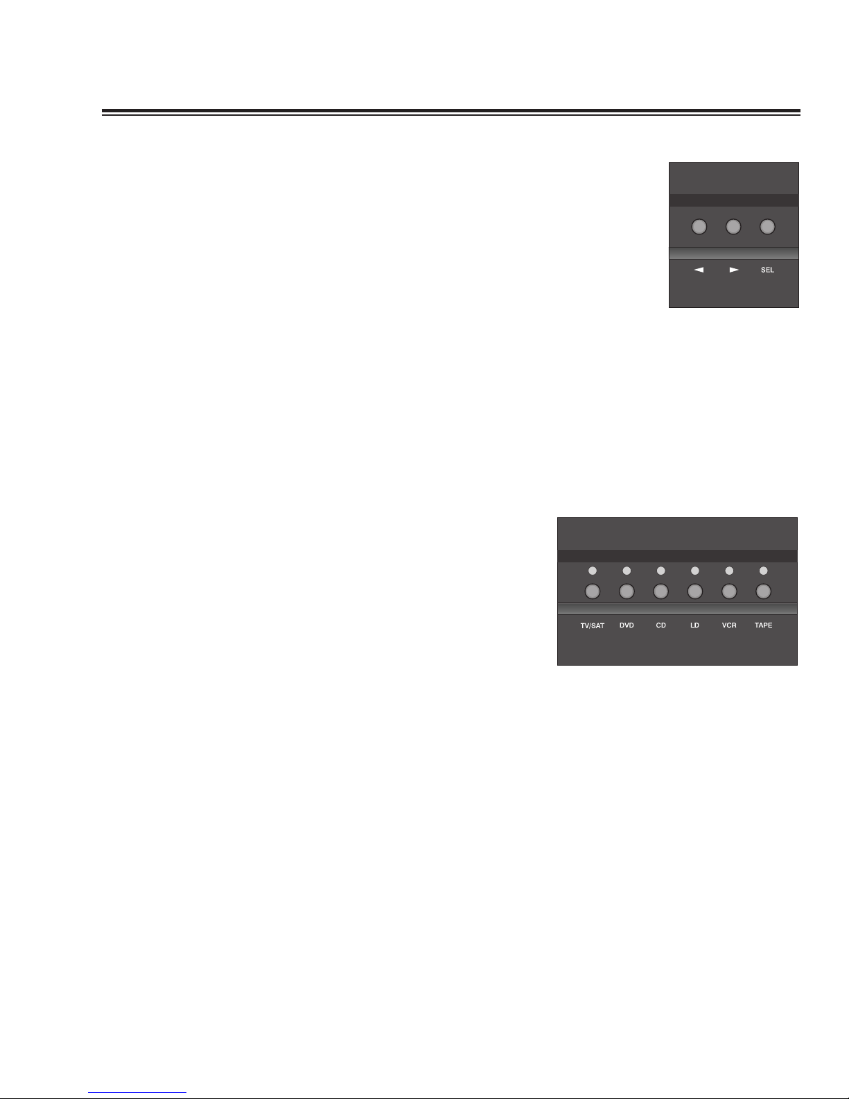
6. Menu Control Buttons
These three buttons labeled "<", ">", and "SEL" (SELECT) are
used to control the menu/setup functions displayed on the
LCD. To enter a menu mode, you can press any one of these
buttons. This will bring up the main menu.
All of the SP1 set-up and calibration operations are done using
these buttons and the LCD screen.
Navigating any menu or sub-menu is done using the two
arrow (< >) buttons. Once the desired submenu or function
is highlighted, pressing "SELECT" will make it the current
menu or function.
To exit a menu, or back up a step use the arrow buttons (< >)
to highlight the 'X' displayed in the lower right hand corner
of the LCD window and press "SELECT".
7. Source Selection Buttons and Indicators
Pressing any one of these buttons will instantly switch the
SP1's analog and digital inputs to read the indicated source.
If the SP1 is in its digital mode, as soon as any input is
selected and switched, the decoder will automatically try to
determine the new bitstream's type and mode
7
Page 10

8
Mode Selection Buttons:
8. Digital Mode and Indicator
This button operates as a three way toggle function. The LED
immediately above the button has two colors - RED and
GREEN, and an OFF mode where it is not illuminated.
When Digital Mode is selected, the decoder will automatically
default to a digital signal for the selected input if one is
present.
If a digital signal is present and detected, the SP1 will
automatically determine the type of bitstream and select the
proper decoding mode.The indicator LED will turn green
when this happens.
If NO DIGITAL SIGNAL is detected the SP1 will default back
to the analog input for the selected source.This also
automatically puts the SP1 into its Digital Standby Mode.
When this occurs the LED indicator will turn RED
In this mode, the decoder will continually check the selected
source inputs for the presence of a digital signal.If one is
detected, the SP1 will automatically switch over to the preselected digital operation mode for that source.
To defeat this auto-digital detect mode you must press the
button again. If you do the LED will go OFF.
When this mode of operation is selected the SP1 will look at
ONLY its analog inputs. If a digital signal does appear the SP1
will NOT recognize it and will remain in its analog only mode
until you press the Digital button again to either select the
digital source or place the SP1 into its auto detect mode as
explained above.
9. Analog Pro Logic and Dolby Digital Pro Logic Mode
Switch
In digital mode, this button will produce Pro-Logic decoding
on any 2 channel bitstreams.When this function is operational
the LED will turn green.
If Pro Logic decoding is NOT allowed with the current
bitstream (such as when a DTS signal is present), nothing will
happen when the button is pressed.
In the SP1 's analog mode, this button will produce standard
Pro Logic format decoding on the selected analog input(s).
Page 11

10. Stereo and Stereo Downmix Mode
If this button is selected and the supplied bitstream is more
than 2 channels, the decoder will automatically implement a
stereo downmix. Otherwise, analog or digital two channel
signals are passed as conventional stereo.
11. Mono and Mono Downmix Modes
If this button is selected and the supplied bitstream is more than
1 channel, the SP1 software will create a Mono mix of all signals.
Pressing this button repeatedly, will direct the mono signal to
different speakers, if your system has them available and the
SP1 was setup to recognize your speaker layout during initial
calibration. The options in order are:
Mono LR (Left, Right),
Mono Centre
NOTE: Downmix [stereo or mono] is a software based automatic mixing
function available within the SP1. This process exists because whenever
the number of active decoder outputs or loudspeakers selected in setup is
less than the number of channels in the Dolby Digital program, some
channel combining will be necessary to present the program on the
available number of channels/loudspeakers.
As a part of any program's production, its producers can set
and adjust the type and ratios allowed for downmixing
somewhat to ensure optimum results without compromising
the full Multichannel balance.This is accomplished by
including specific data within the Dolby Digital bitstream
which represents different mixing coefficients for the centre
and surround channel signals.
These will be detected by the SP1 and used to produce the
downmix if this mode is selected.
12. Music Modes
Pressing this button will illuminate the LED and sequentially select
one of the five available music decoding modes.The five options
are: Party, Natural, Stadium, Club, and DTS Music
(see * page 21)
.
NOTE: When you choose to listen to a DTS encoded music CD or music
video DVD or LD, please switch to the DTS Music setting and de-activate
any other settings such as THX processing as they are not needed.
Please see Appendix -- A for more details on each of these
proprietary music modes.
9
(only when a DTS digital
bitstream/signal is present)
Page 12

10
13. THX Button
Selecting this function (LED illuminated) will automatically
incorporate the THX post processing option for all surround
modes.
(please SEE Appendix B FOR MORE Information)
NOTE: When you choose to watch a DTS encoded DVD or LD movie,
please be sure that the SP1 is in the DTS Movie mode. You may choose
to use the THX features to enhance playback of DTS bitstreams for
motion pictures. Sources originally mixed for a large environment such
as motion pictures may benefit from THX processing.
14. Bypass Button
This button toggles the unit in and out of bypass mode. In
bypass mode (LED illuminated) all of the DSP circuitry is
bypassed, allowing a completely analog circuit path, identical
to the reference standard Bryston BP-25 pre-amplifier.
Only standard format Stereo operation is permitted in this
mode - all other functions are disabled.
15. Analog Balance
This control governs the balance of the analog bypass circuit.
It will only function if the SP1 is in bypass mode.
16. Master Volume
This is the Large Knob located on the far right side of the
front panel. It controls the Master Volume in all modes. It is
fully motorized and can be operated from the remote control
or by hand. It is the final level setting control on the SP1, and
determines what output level will be supplied to the
connected power amplifiers, but not the tape/recording
outputs. It takes into account any speaker level trim
adjustments made during the SP1's setup.
Page 13

THE SP1 Rear Panel
INPUT AND OUTPUT Connections
1. Balanced and 2. Unbalanced Outputs
The SP1 offers both balanced and unbalanced outputs for
power amplifiers or powered loudspeaker systems.The type
you select to use will be determined by the input
configuration of your amplifiers or self-powered loudspeakers.
3. Analog Inputs
A paired stereo analog input with gold RCA jacks (labeled L
and R, for Left and Right) is provided for each source button
on the front panel.
The sensitivity of these Inputs is set to the industry standard
of 2 Vrms, which should accommodate the vast majority of
available source components. In Bypass mode, the input
sensitivity is equivalent to the BP-25 preamplifier.
4. Digital Audio Coaxial Inputs
The CD,Laser Disc, DVD and TV/Satellite front panel
selectable sources are also supplied with a standard SPDIF
gold RCA jack digital audio input.These four inputs will
accept any standard SPDIF source including DAT, CDR and
similar components.
5. TOSLINK Digital Audio Optical Inputs
The SP1 offers two assignable TOSLINK optical inputs.These
can be designated to any input using the OS menu on the
LCD screen. Please note that if you choose to assign an optical
input to an input with a coaxial input, the coaxial will be
over-ridden and the optical input signal will be used by the
SP1.The pro model replaces the two TOSLINK connectors
with a single AES/EBU connector.
11
Figure 6: Rear Panel
Figure 7: the AES/EBU Pro Digital XLR
connector
Page 14

12
Setting the Optical Audio Input Assignment
i. Enter the main menu by pressing on one of the menu
buttons on the SP1 front panel. Move the cursor to "OS".
Hit 'Select' - You are now in the ‘Other Settings’
(Optical/THX) Menu.
ii. Move the cursor to the Optical Input (OPT1 or OPT2) you
want to change the input assignment for. Hit ‘Select’.
iii. Now you can assign the optical input to any one of the 6
inputs selectors. Doing this will override the digital coax
connector on that input. Hit ‘Select’ when finished.
NOTE: On the pro model, ‘AES’ will show up in the ‘Other Settings’
Menu (instead of OPT1 and OPT2), to setup the AES/EBU input
assignment.
6. Tape/Recording Outputs
The SP1 provides two analog outputs for the TAPE and VCR
sources. The front panel selected input signal is always routed
to these tape outputs, except when TAPE or VCR is selected.
In those cases the appropriate output is automatically muted
to prevent feedback.
7. Remote 12V Trigger Outputs
Two trigger outputs are provided.The output labeled
"ON/OFF" provides a 12V voltage level whenever the unit is
fully powered up. When the unit goes into standby, the level
is 0 Volts.
The output labeled "AUX" is programmable from the LCD
menu as described below.This means that the terminal
supplies the 12-Volt signal only when you switch to certain,
specified inputs.
The Centre (Common or Ground) terminal is always used
with the "ON/OFF" or "AUX" terminals to complete the circuit
loop. The 12-Volt connector will accept
1
/4- inch stripped
wire ends, inserted into the square holes provided, and the
adjacent screws carefully tightened to hold them in place.
These can be used to control any Bryston Power amplifier
and many other components such as motorized screens and
drapes. Be sure to determine what type of trigger signal the
selected components requires and what function will be
enabled by the trigger signal's voltage.
Figure 8: Highlight ‘OP1’ in the ‘Other
Settings’ Menu
Page 15

Programming the AUX Trigger Output
i. Enter the main menu by pressing on one of the menu
buttons on the SP1 front panel. Move the cursor to "OS".
Hit 'Select' - You are now in the Other Settings
(Optical/THX) Menu.
ii. Move the cursor to "T". (T = Trigger) Hit ‘Select’. Now
you can assign the AUX Trigger output to ON or OFF, for
each of the 6 input sources.
iii. To change the source, use the "<" button.To toggle the
trigger setting On or Off, use the ">" button. Hit ‘Select’ to
exit when finished.
8. Aux IR Receiver
The Aux IR Input is a miniature mono phone jack connector.
This is used to connect externally mounted IR LED receivers,
or other extenders that provide modulated IR receiver data.
Data is retransmitted by by an IR LED mounted near the front
panel IR receiver.
9. RS-232 connector
This connection provides for control of an external video
switcher, or remote control of the SP1 functions via a
computer interface or AMX/Crestron type controller. Please
contact your dealer or Bryston to make use of this optional
feature and determine which devices are compatible.
10. IEC Power Connector
11. Fuses
Please note that the Analog and Digital power supplies are
fused separately. Replace fuses ONLY with an exact equivalent
to avoid damage to the SP1.
12. Master Power Switch
13
Figure 9: Trigger Assign Menu
Page 16

The SP1 Remote Control
Operating the SP1 from the Remote Control is similar to the
front panel operation, with a few additions and omissions.
1. Source Select Buttons
These buttons are used to select the desired source, and
function exactly like their equivalent buttons on the front
panel.
2. Mode Select Buttons
These buttons are used to change the SP1 decoding mode,and
function exactly like their equivalent buttons on the front
panel.
3. Mute Button
Pressing this button will fully mute the output of the SP1.
4. Volume/Trim Buttons
These buttons increase and decrease the
master volume. When the SP1 is in its
Test/Noise mode, these buttons are used to
adjust the level trim for each individual
speaker.
5. Light/Test Button
When pressed momentarily, this button will illuminate the
backlight on the Remote Control. If pressed for more than 3
seconds, the SP1 will enter the Test/Noise mode. Please see
Page 18 for more details on this mode.
6. Power Button
Pressing this button will toggle the SP1 in and out of the
Standby power mode.
{Installers: please contact Bryston technical support for information about
Discrete On/Off control}
14
Page 17

SET UP and CALIBRATION OF THE SP1
NOTE: In most operating menu modes the last segment of line 2 of the
display will show an "X" for EXIT (a sample screen is shown below - fig
10). Choosing (highlighting) this position in the display and pressing the
Select button (see below) will "EXIT" back to the previous menu or out of
the particular menu or mode completely depending on where within the
menu structure you are at the time. A more detailed explanation is given
below in the section on menu control buttons.
In order to fully enjoy the capabilities of the SP1 you or your
dealer must first set-up and calibrate the SP1.This is a critical
step in insuring that all your loudspeakers are properly
designated within the unit and that all levels and delays are
properly set.
To accomplish this process the following tools are needed:
Tape measure or other means of determining the distance of
each speaker from the chosen listening positions.
Sound Level Meter - This device insures that all loudspeaker
levels are precisely matched and set accurately.This step
cannot accurately be done by ear, a test instrument should be
used to ensure proper calibration. (The Radio Shack Analog
SPL meter is inexpensive and eminently suitable for this task.
Your dealer may have one.)
PLEASE NOTE: If for any reason you are not sure that you can accomplish
this calibration task or have any doubts as to how it should be done,
please contact your dealer or Bryston technical support BEFORE
attempting this process. Most Bryston Dealers can provide this service.
Please contact your dealer for their policies and procedures in this regard.
15
Figure 10: Highlight "X" to EXIT
Page 18

System Setup and Configuration
Setting the Speaker Configuration
Before calibrating levels you must first tell the SP1 about your
loudspeaker configuration.To do this:
1. First enter the main menu by pressing on any one of the
menu buttons (< - > or SELECT).
2. Next move the cursor to "SP". Hit 'SELECT' - You are now in
the Speaker Menu.
3. Move the cursor to the speaker(s) you want to change the
configuration for using the arrow keys (LR, C, SUR, SUB).
Hit 'SELECT'.
The options available in this menu are:
For LR you can select SMALL OR LARGE
For CENTRE (C) you can select SMALL, LARGE or NONE
FOR SUR(OUNDS) you can select SMALL, LARGE or NONE
FOR SUB(WOOFER) you can select YES or NO
The SP1's default factory settings as shipped are:
Front = LARGE, Centre = NONE, Surrounds = SMALL,
Subwoofer = YES.
4. Once you have completed selecting the settings that match
your particular speaker systems please move the cursor to
the (X) and press SELECT to exit this menu.
NOTE: LARGE VS SMALL SPEAKER SETTINGS:
It is very important that you understand what is meant by the
LARGE and SMALL settings in this menu.They do not refer to
SIZE, but to the ability of the particular loudspeaker system to
handle low bass/low frequency information. It is very
important that you consult your loudspeaker providers
instruction manual or the company regarding the capabilities
of your particular system with regard to low bass/low
frequency reproduction.
Please note that all THX certified
loudspeaker systems are SMALL since a subwoofer is a part of any THX
certified loudspeaker system.
It is strongly recommend that you
consider using a subwoofer for any system which you expect
16
Figure 12: Speaker Configuration Menu
Figure 11: Setup Menu
Page 19

to effectively handle the low frequency dynamics of modern
motion picture soundtrack sources such as DVD or HDTV
feeds, and many other discrete multi-channel programming
sources. If in any doubt choose small, especially if you are
using a subwoofer, since this will insure that all the
appropriate low frequency information is directed to the
subwoofer where it can be most effectively handled.
Setting the Channel Delays
In this step you will need to measure within one foot the
distances from your chosen listening/viewing position to the
various loudspeaker locations in your system.
You will need the tape measure or other means of making
these measurements.You should record this data for future
reference.
1. Now, make a measurement from the chosen seated position
to each loudspeaker.
2. Next, enter the main menu by pressing on one of the menu
buttons on the SP1 front panel. Move the cursor to "DLY".
Hit 'Select' - You are now in the Delay Menu.
The SP1 automatically calculates the required delay time per
speaker using the data entered as distance from the
listening position. Delays are implemented using DSP RAM
and have a maximum value.
IMPORTANT: It is recommended that the closest speaker is entered first.
The SP1 will calculate the maximum allowable distance from the listening
position for the remaining speakers. Please note that delay is
represented in feet. For reference, One foot (0.3048 meters) =
approximately 1 millisecond of delay.
3. Move the cursor to the speaker you want to set the
distance/delay for (L C R LS RS SB). Hit Select. Now you
can adjust the Delay value which is equivalent to the
distance you measured for the selected speaker using the
arrow buttons. Set the delay for each speaker in your system
to the nearest foot/meter. Rounding up is OK.
4. Hit SELECT or [X]Exit when finished.
The SP1's default factory settings as shipped are 10 feet to
every speaker, resulting in zero overall delay.
17
Figure 13: Delay Menu
Page 20

Calibrating and Setting Levels / Channel to Channel
Balance.
1. Position the Sound Level Meter at the Centre point of your
listening area, at average ear height [ approximately 40 - 46
inches {102 - 117 cm.} with its microphone positioned
vertically (pointing at the ceiling). DO NOT aim the sensing
microphone at the speakers, as this will produce inaccurate
level indications.
2. Using the SP1 Remote, press and hold for approximately 3-5
seconds the key labeled "Light - Hold for TEST". It is the key
located directly below the Stop-Sign shaped "MUTE" key on
the remote control.
IMPORTANT: The Test-Noise Mode can only be initiated from the SP1
remote, and not from the front panel.
The shaped pink-noise test signal will begin with the left-front
loudspeaker. If the signal does not appear in this speaker
please stop the process and check your wiring and
connections for proper configuration.
3. Using the volume up/down arrows on the remote or the
arrow keys on the SP1 adjust the level of the noise so that it
reaches a predetermined level on the Sound Level Meter.
This is the level to which you will set ALL speakers using
the test signal and meter.The recommended calibration
level is no less than 80dB/SPL.THX specifications call for a
level of 85dB/SPL at the listening position.
4. Hit the "TEST" button again to sequence the noise to the
next speaker. The sequence is L -> C -> R -> RS -> LS ->
SUB. When the cycle is complete, the test noise signal will
end, and the unit will switch back to the previous mode. If
any output is unused (as defined by ‘NONE’ in the Speaker
Configuration Setup), the noise sequence will automatically
skip to the next speaker in the sequence.
Setting Channel Levels without Pink Noise
If you wish to adjust the speaker level trims without using the
pink-noise test signal, this can be done from the Front Panel
menu system.
1. First enter the main menu by pressing on any one of the
menu buttons on the SP1 front panel (< - > or SELECT).
2. Next move the cursor to "LVL". Hit 'SELECT' - You are now
in the Level Trim Menu.
18
Page 21

3. Move the cursor to the speaker(s) you want to change the
level for using the arrow keys (L, C, R, RS, LS, SUB). Hit
'SELECT'. Now you can adjust the Level for the selected
speaker using the arrow buttons.
4. Hit ‘SELECT’ when finished, and repeat Step 3 to change the
Level Trim for any of the other speakers.
Setting the THX Subwoofer Limiter or "Bass Peak
Level Manager"
1. Enter the main menu by pressing on one of the menu
buttons. Move the cursor to "OS". Hit 'Select' - You are now
in the Other Settings (Optical/THX) Menu.
2. Move the cursor to 'BPLM'. Hit Select. [BPLM=Bass Peak
level Manager]
You will see the following screen.
3. Hit ‘SELECT’ and you will see the adjustment screen picture
below appear, and you will hear a low level Pink Noise
signal coming from your subwoofer and/or large speakers.
Now you can adjust the value of the subwoofer limiter (-40 to
0 dB). Slowly increase the level by pressing the ">" button
(display counting up from -40) until you hear overload/
distortion/bottoming/popping from your subwoofer(s). When
you do, reduce the value shown by 1dB and Hit ‘SELECT’ to
save the setting.You can always return to this menu to make
further adjustments if needed. For more information on the
BLPM see the THX section in the appendix.
19
Figure 14: ‘Other Settings’ Menu
Figure 15: BPLM Routine Query
Figure 16: BPLM Adjustment Screen
Page 22

Setting the BPLM without Pink Noise
To adjust the BPLM setting without running the Noise routine,
Enter the BPLM as above, but when the SP1 prompts "Do
BPLM Routine?", use the arrow keys to select ‘NO’ and hit
‘SELECT’. This will bring up the numeric value of the BPLM
setting without the noise signal.You can now adjust the value
using the arrow keys, and hit ‘SELECT’ when finished.
Caution: If the BPLM is set to "OFF" or "0", the Bass Limiting
function is disabled. In this case, you may run the risk of
speaker damage due to bass overload. Please be sure that
your speaker system can handle high bass levels before
disabling the BPLM.
Acknowledgements
The SP1 is manufactured under license from Lucasfilm Ltd.
U.S. Patent numbers 5,043,970; 5,189,703; and 5,222,059.
European patent 0 323 830. Other patents pending. Lucasfilm
and THX are trademarks of Lucasfilm Ltd.All rights reserved.
The SP1 is manufactured under license from Dolby
Laboratories. "Dolby", "Pro Logic" and the double-D symbol are
trademarks of Dolby Laboratories. Confidential unpublished
works. „ 1992-1997 Dolby Laboratories, Inc.All rights reserved.
The SP1 is manufactured under license from Digital Theater
Systems, Inc. U.S. Pat. Number 5,451,942 and other world-wide
patents issued and pending. "DTS" and "DTS Digital Surround"
are trademarks of Digital Theater Systems, Inc. „ 1996 Digital
Theater Systems, Inc.All rights reserved.
ALL TRADEMARKS, REGISTERED MARKS,AND LOGOTYPES/
SYMBOLS ARE THE PROPERTY OF THEIR RESPECTIVE
COMPANIES,AND ARE USED WITH THEIR PERMISSION.
APPENDIX A -
SP1 MUSIC MODES
Pressing the MUSIC mode button will illuminate the LED and
let you sequentially select one of the four available music
decoding modes for 2 channel signals.
These special modes are designed to expand your enjoyment
of almost any 2 channel music source and many other 2
channel signals.You are encouraged to experiment with the
options on various sources. Not all will supply something you
may like, but there are so many variables that it does pay to
take a few moments to listen to the options.
The custom SP1 Music Modes use a set of proprietary DSP
algorithms to create a set of simulated signals using the
original left and right 2 channel data and feeds these to the to
centre and surround speakers.The Music Mode algorithms do
NOT in any way modify the original 2 channel signals that are
sent to your main left and right channel speakers.
The five options you have are:
Party:
This mode is designed for "Party" situations, where you may
have a room full of people, who have no direct path to the
main speakers. The Centre channel is not used. Left is copied
20
Page 23

to left surround and right to right surround, creating
essentially a giant Stereo image throughout your space.The
Music mode delay settings have no effect in this mode.This
works especially well on lots of pop/rock music and also for
many recordings with good natural ambiance.
Natural:
This mode enhances basic stereo reproduction by using the
inherent acoustics recorded within the source material. It is
generally suitable for use with all kinds of music. If the source
material was surround encoded or recorded in an acoustically
oriented manner (such as a lot of classical music and many
live recordings) this mode can provide truly spectacular
effects and an enhanced sense of the space in which the
music was being performed.This mode sends a summed L+R
signal to the centre channel.A difference signal (produced by
L-R) is decorrelated to both surround channels without any
timbral coloration.
Stadium:
This mode produces a Stadium and or simulation of a Large
Room type effect. It generates strong reflections and is most
suitable for live music events,simulcasts, and most live sports.
The L+R sum signal is sent to the centre channel, while the
same signal is also sent through a custom echo algorithm to
the surround channels.
Club:
This mode closely simulates a nightclub or a small room type
of space using a fast decay echo algorithm. It nicely recreates a
small room full of people, and is very useful with pop and
rock music.The L+R sum signal is sent to the centre, and also
to the custom echo algorithm where it is also lowpass filtered
before being sent to the surround speakers.
DTS MUSIC
This mode is used ONLY when a DTS bitstream is detected. It
is optimized to provide proper playback of DTS encoded
musical material from DVD, LD or CD sources.A similar mode
called DTS Movie is available for playback of DTS encoded
motion picture soundtracks from DVD or LD sources.The SP1
will auto-detect DTS bitstreams and select the correct mode
automatically in the vast majority of cases.You may manually
select these modes ONLY if a DTS bitstream has been
detected initially.
(Please note that the apparent effect of the Music Mode can be adjusted by
altering the delay parameters and channel volume of the centre, left surround
and right surround speakers using the appropriate menus).
Remember there really are no "correct" settings that will work
equally well for all kinds of music.You may need to adjust the
parameters and mode depending on the music material.
21
*
Page 24

22
APPENDIX B - THX INFORMATION
Below is a summary of issues and information related to the
proprietary and patented THX processing incorporated used
in the SP1.The available space cannot include all the available
information on this topic.Therefore, if you want more
information or wish to research the topic in more detail
please use the THX website at WWW.THX.COM.The
information below was condensed from documentation
supplied by THX.
When you choose the THX option for all surround decoding
modes within the SP1, by pressing the THX button on the
front panel or the remote an additional processing method is
activated.
The additional signal processing used in this mode is the
result of extensive research, testing and refinement by the
technical and engineering staff at LucasFilm, Ltd.
All movie soundtracks regardless of their original encoding
format (Dolby Digital, Dolby Pro-Logic, DTS, Stereo or Mono).
The THX mode would not normally be activated for music or
movies that were made specifically for television or other
broadcast shows such as sports programming.The THX
processing, designed to compensate for large room mixing
environments is not required for these programs because they
are normally mixed/post-produced in small room
environments, as opposed to the large room environments
normally used for theatrical motion picture mixing/postproduction.
The SP1's THX mode adds additional DSP to the either the
Dolby or DTS processing already in place to help create a
more precise match between the sound produced within a
commercial motion picture theater and the sound produced
in your residential 'theater'.
THX's research shows that this is necessary because, all of the
multi-channel film sound formats were originally designed and
spectrally balanced for use within large commercial movie
theaters.
Moreover, the specially equipped and designed theater used
by the sound mixing professionals to produce the final
theatrical audio track on any film (called a 'dubbing stage') is
also considerably larger than your 'home theater' since it was
created to replicate the environment of a typical commercial
cinema space, not your home theater space.
It is in those "dubbing stages" that the dialogue, sound effects
and music are all individually recorded and mixed to a six
(5.1) or four channel(Pro- Logic) soundtrack for release in
commercial movie theaters.This is the same soundtrack that is
later released on videotape and DVD for playback in a Home
Theatre system.
During their research, the THX engineers identified the
fundamental tonal and spatial errors created when Theatre
environment film sound tracks are reproduced in residential
spaces.
Page 25

The SP1, contains special processing designed by THX to
correct those errors and restore the appropriate tonal and
spatial balance to a movie soundtrack, so that you can hear
what the film's producer/director intended.
This processing includes:
1. An Electronic Crossover
Electronic Crossovers allow the use of the more typical
residentially sized smaller main speakers by sending the bass
signals to a separate subwoofer.
With Dolby Pro Logic sources, only the main front channels
pass through the crossover. For Dolby Digital or DTS sources,
all channels pass through the crossover.
2. Re-Equalization
This processing is designed to correct the excess high
frequency content or brightness of movie soundtracks.
This excess brightness occurs because as noted above motion
pictures are mixed in spaces representing the size and
acoustics of movie Theatres which incorporate a special
international standard called the "X-Curve".This frequency
response curve is used because there is a natural high
frequency rolloff (loss) when sound sources are some distance
from the listener.This is the case with the speakers in a
commercial cinema.
When the speakers are much closer, such as in a home
cinema, the soundtrack will be excessively bright.
The THX processing uses a special Re-Equalization Curve,
designed for home environments, to restore the correct tonal
balance of a movie soundtrack.
3.Timbre Matching
In a commercial Theatre, the multiple loudspeakers used are in
front [ the LCR speakers], and all around you [the surround
speakers located along the sides, and behind you].The many
surround speakers are carefully equalized to match the front
channels.
The THX Timbre Matching processing corrects the surround
tonal balance to match the front channels so you hear one
continuous soundfield.
Additionally for the majority of residential systems, the system
must also correct for the fact that only two surround speakers
are used.
The THX processing help to insure that there is always smooth
sound movement from front to the surrounds.This helps to
place you, the listener, inside the movie experience.
4. Adaptive Decorrelation
Additionally the THX processing system is designed to deal
with the fact that in Dolby Pro Logic mode (the system used
on the vast majority of videotape versions of movies) the
surround channels are monophonic.
23
Page 26

In a commercial Theatre, you don't detect this because the
large number of surround speakers and the reflections within
the room prevent your two ears from receiving equivalent
signals.
The THX Decorrelation Circuit discreetly changes the time
and phase of one surround channel versus the other
preventing your left and right ears from hearing identical
signals, and helping to re-create the spacious and ambient
sound you experience in a commercial Theatre.
In Dolby Pro-Logic mode, with THX processing selected, the
Adaptive de-correlation is operative at all times since the
surround signals are entirely monaural.This proprietary THX
processing algorithm also works effectively in Dolby Digital
and DTS film playback modes.
Even though motion picture sound-track mixing engineers
now have the option in these formats to create different
information for the discrete surround channels these encoding
processes offer, a significant portion of the overall soundtrack
may still be monaural.The unique adaptive nature of the THX
de-correlation processing detects monaural signals, and only
operates when such signals are present.
You can safely leave the THX processing engaged for all
motion picture playback modes, with the assurance that the
processing will only affect the type of signals it is designed to
enhance.
5. Bass Peak Level Manager
To diminish the chance that your subwoofer will overload from the large
amount of bass, often present in the LFE channel the system uses a Peak
Management circuit which works with the data you supplied during
speaker setup to help match the subwoofer output to your specific
subwoofer's capabilities.
Please note that the factory default for the BLPM is -20 dB since the
capabilities of your specific subwoofer are unknown.
In the SP1 setup and calibration section above ,the final step you should
have performed was to set the BLPM for your subwoofer's specific
capabilities. If you have not does this you should return to the setup section
(see page zxx) and do this now.
6. Loudspeaker Position Time Synchronization
In an ideal world your theater space would allow you to be an equal
distance from every speaker you have installed.
Unfortunately most residential spaces do not allow this condition to exist.
The THX Loudspeaker Position Time Synchronization circuit allows you to
digitally adjust the apparent position of each speaker in your system for the
best multi-channel imaging and smoothest frequency response.
NOTE: Both the Bass Management(#5 above) and Position Synchronization
(#6 above) settings are accomplished during the system setup operation.
Once completed they normally do not need additional adjustments unless
you change speakers or speaker positions.
24
Page 27

BRYSTON 20-YEAR WARRANTY
Bryston products are warranted to be free from
manufacturing defects for a minimum of twenty
years from the original date of manufacture. This
includes parts, labour and return shipping to the
first owner and all subsequent owners. Warranty
coverage is automatic and commences with the
original date of manufacture which is kept on file
at Bryston.
In the event of a defect or malfunction, Bryston will
remedy the problem by repair or replacement, as
we deem necessary, to restore the product to full
performance.
This warranty is considered void if the defect,
malfunction or failure of the product or any
component part was caused by damage (not
resulting from a defect or malfunction) or abuse
while in the possession of the customer.
Tampering by persons other than factory
authorized service personnel, or failure to comply
with Bryston operating instructions, voids the
warranty.
This warranty gives you specific legal rights and
you may also have other rights which may vary
from province to province and country to country.
BRYSTON SERVICE CANADA:
24 STEINWAY BLVD., UNIT 48
ETOBICOKE, ONTARIO
CANADA M9W 6T8
PHONE: 416-675-2585
FAX: 416-675-3101
BRYSTON LTD.
P.O. BOX 2170, 677 NEAL DRIVE
PETERBOROUGH, ONTARIO
CANADA K9J 7Y4
PHONE: 705-742-5325
FAX: 705-742-0882
BRYSTON SERVICE U.S.A.:
30 COVENTRY ST.
NEWPORT, VERMONT.
U.S.A. 05855
PHONE: 802-334-1201
FAX: 802-334-6658
BRYSTON SERVICE OUTSIDE NORTH AMERICA:
CONTACT YOUR LOCAL DISTRIBUTOR
OR
CONTACT BRYSTON DIRECTLY
OR
www.bryston.ca
Page 28

 Loading...