

Page 1

SP1.7 SCHEMATICS
01 Table of Contents
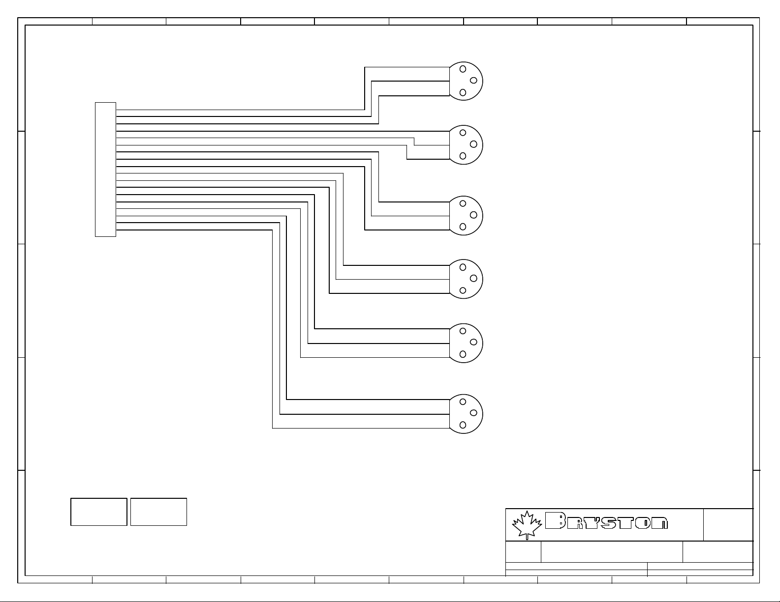
02 BALANCED OUTPUT CONNECTIONS 1.3
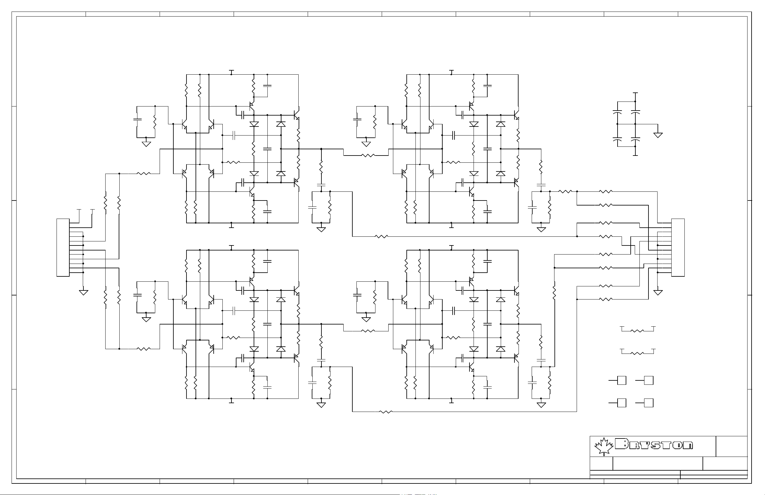
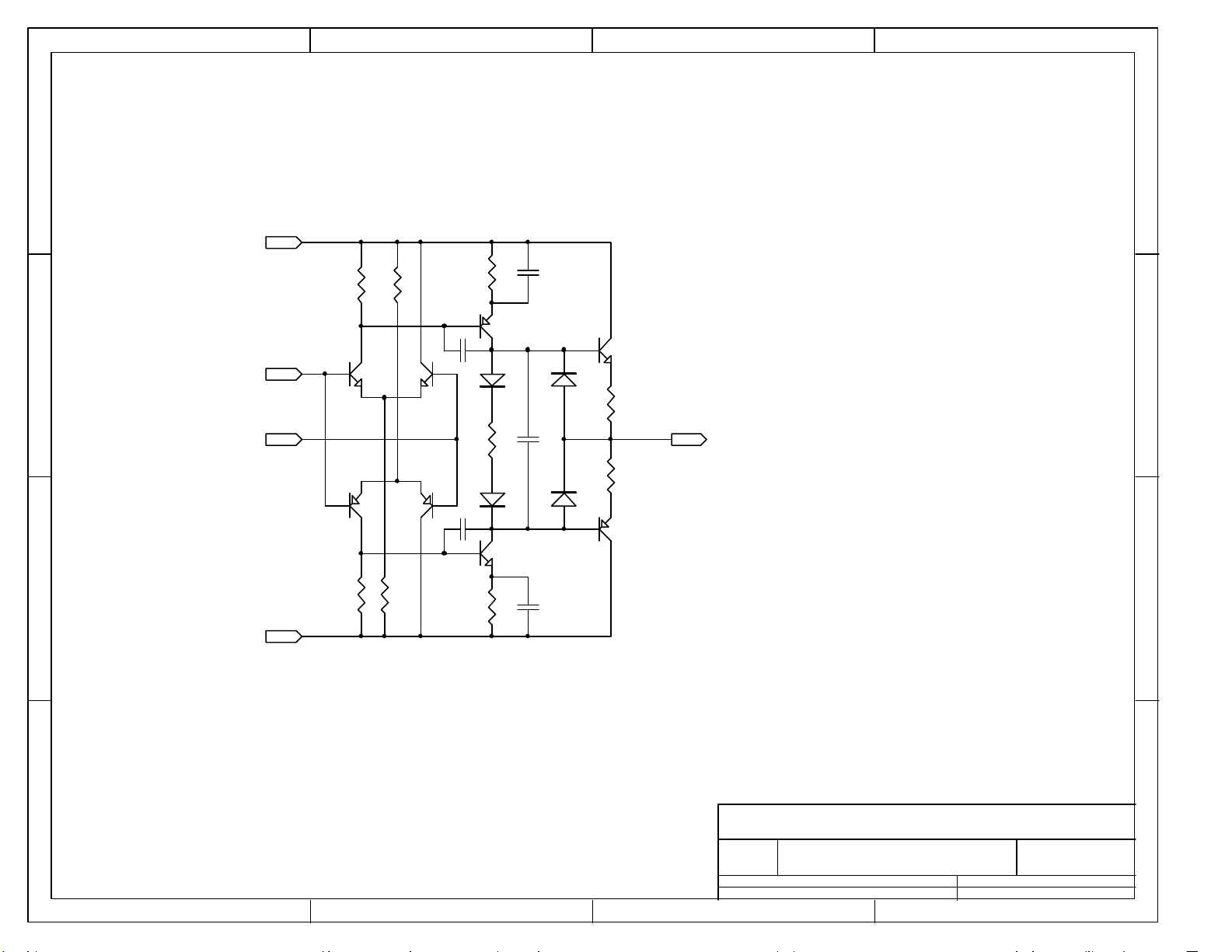
03 BALANCED OUTPUT DRIVERS
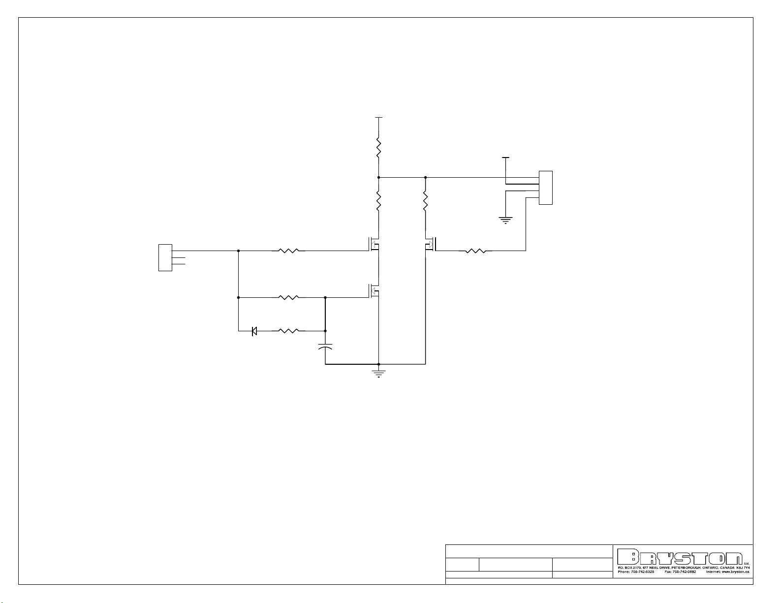
04 MUTE DRIVE 1.0
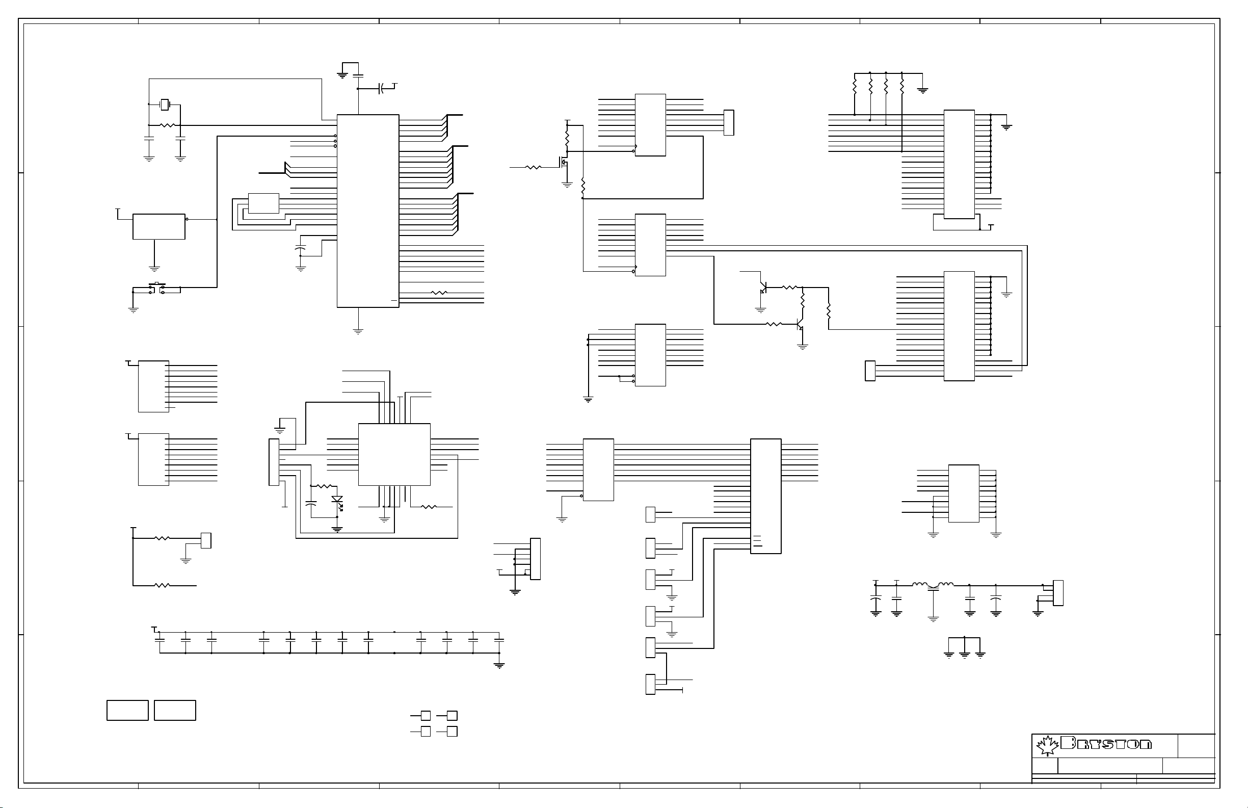
05 MICRO CONTROLLER 1.4
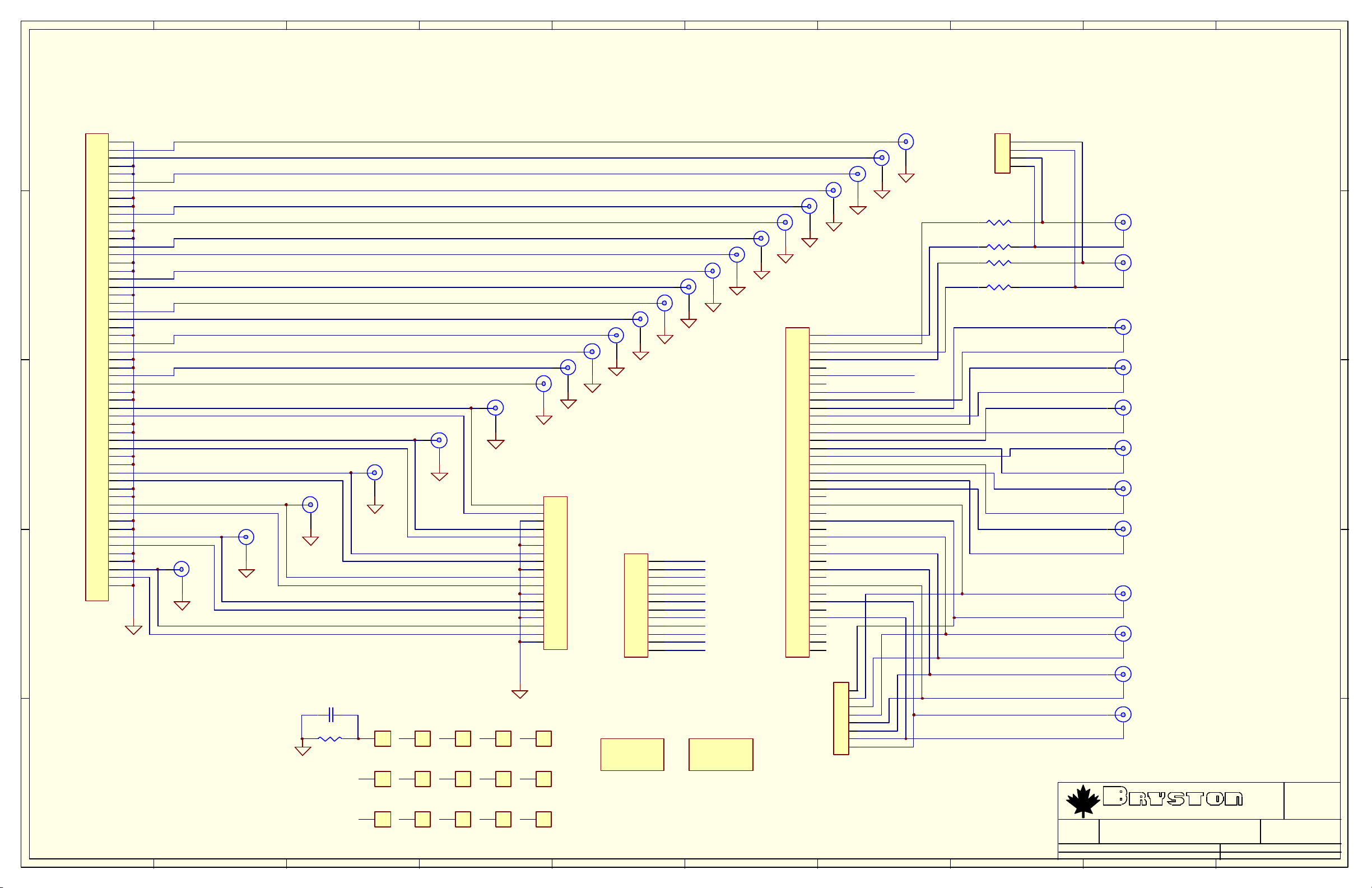
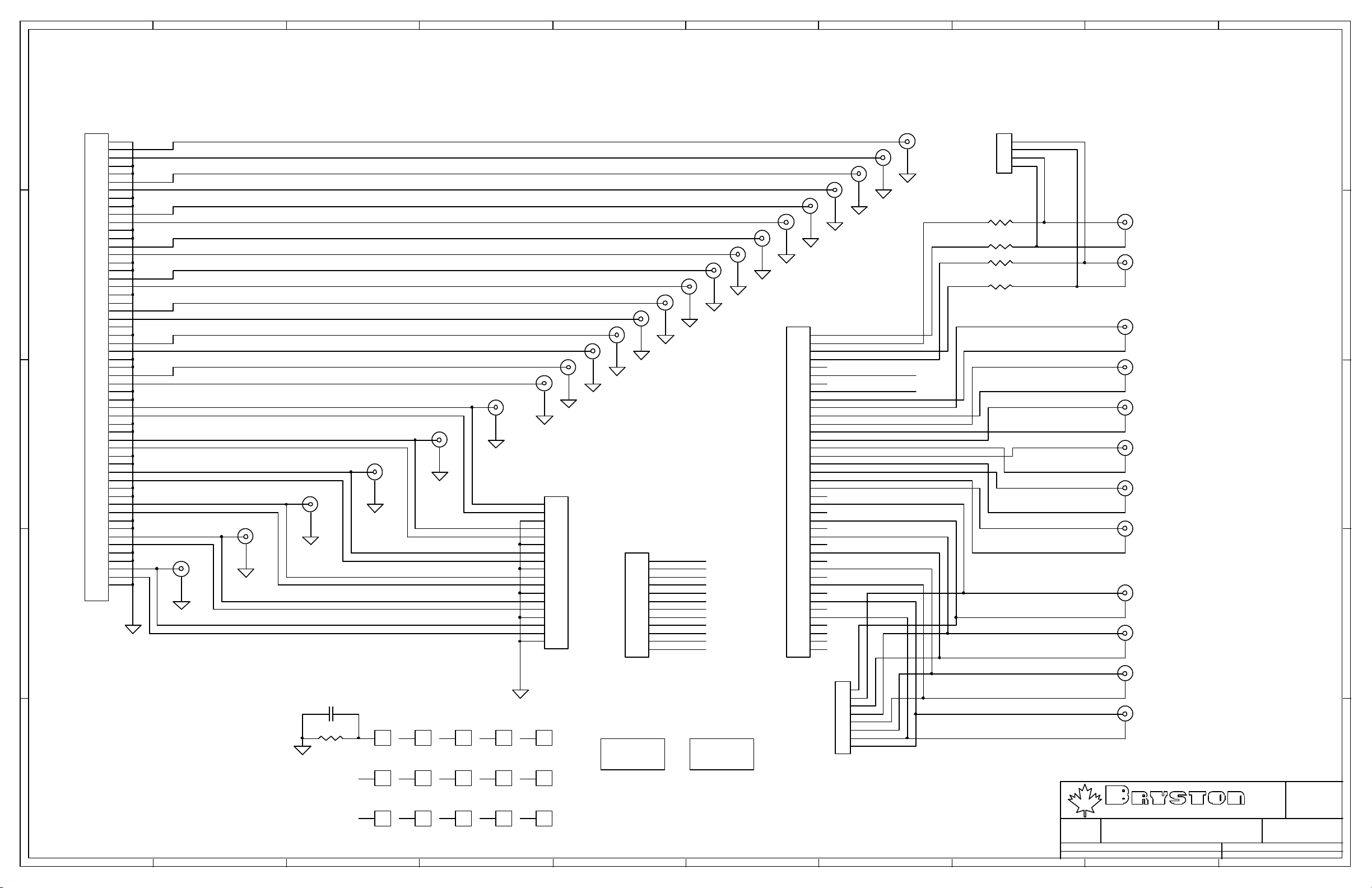
06 REAR PANEL RCA JACK CONNECTIONS 5.2, REV 1.0
07 REAR PANEL RCA JACK CONNECTIONS 5.0, REV 1.0
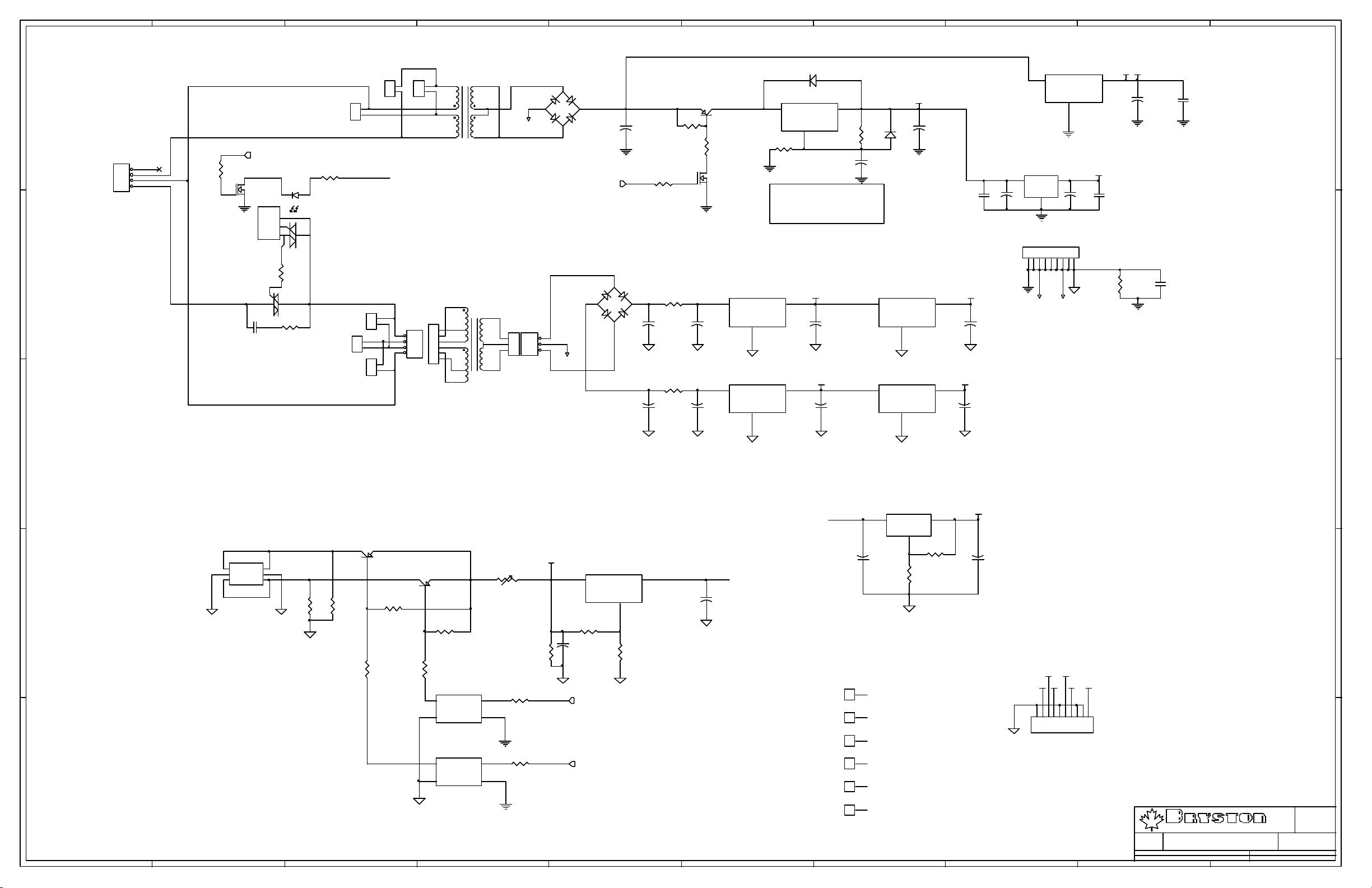
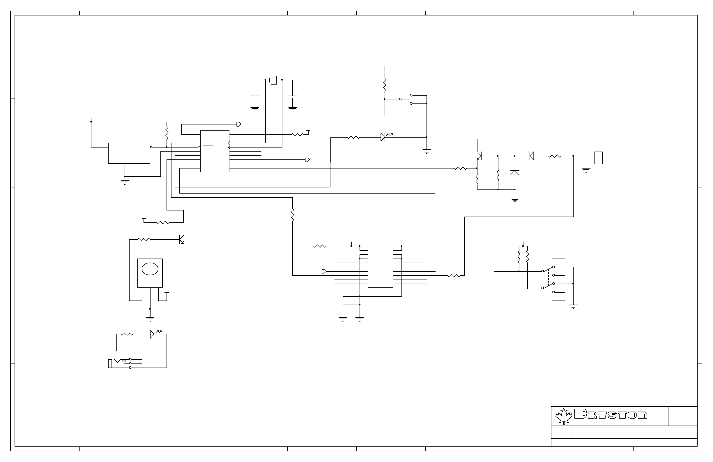
08 POWER SUPPLY 1.9 (pg 1 of 2)
09 POWER SUPPLY 1.9 (pg 2 of 2)
10 MAIN BOARD 1.9 (pg 1 of 2)
11 MAIN BOARD 1.9 ANALOG (pg 1 of 2)
12 MAIN BOARD 1.9 ANALOG (pg 2 of 2)
13 DIGITAL AUDIO ENGINE (DAE) 3033
14 DISCRETE OP AMP #1
15 DISCRETE OP AMP #2
16 DISCRETE OP AMP #3A
17 DISCRETE OP AMP #4A
18 DISCRETE OP AMP #3B
19 DISCRETE OP AMP #4B
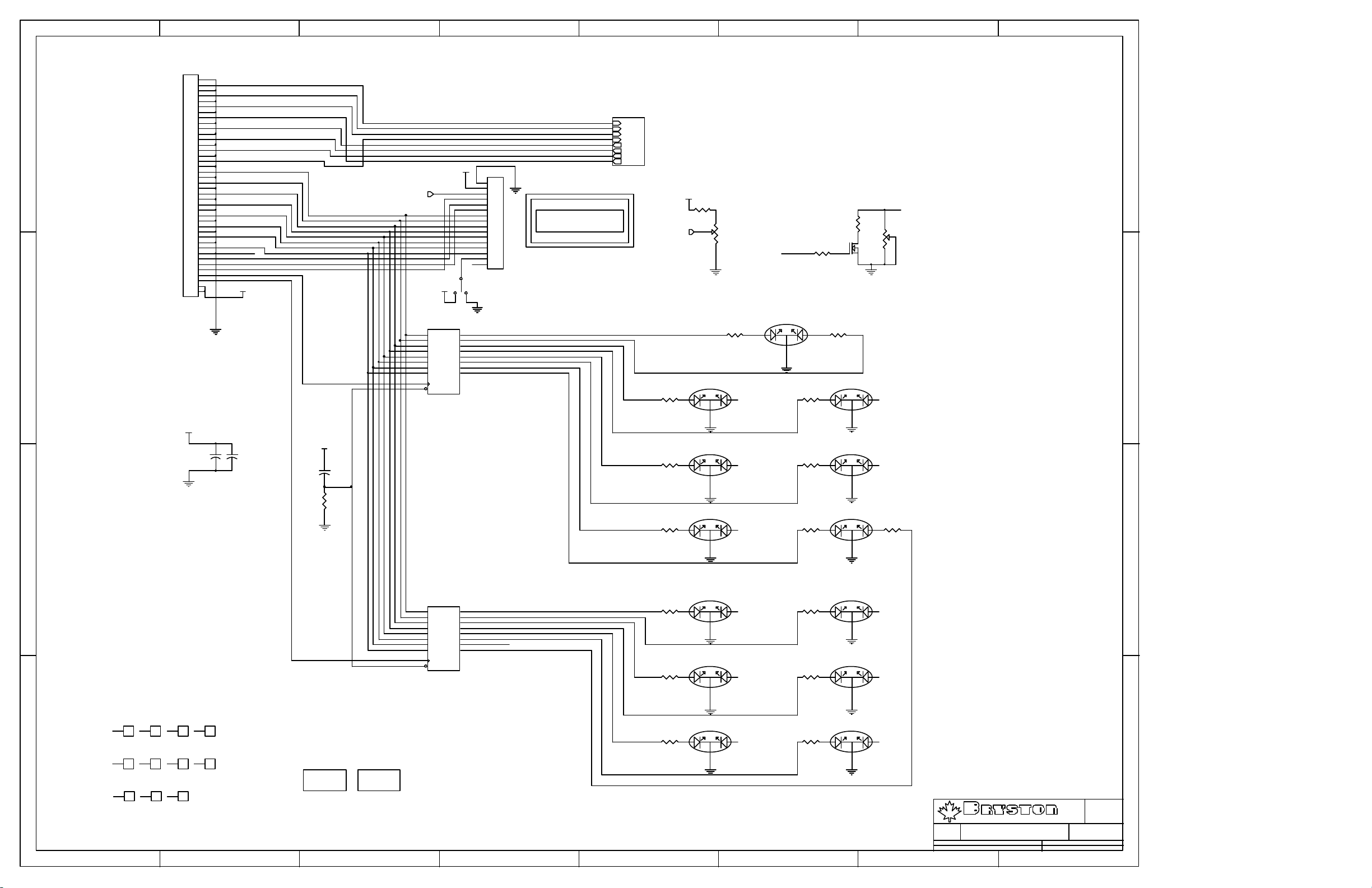
20 FRONT PANEL BOARD
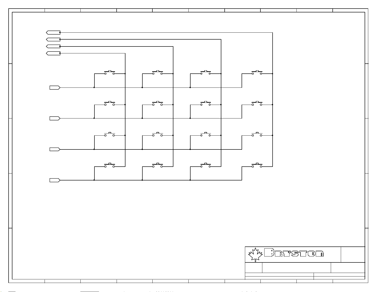
21 TACT SWITCH MATRIX
22 RS232 DUAL PORT BOARD
Page 2
10987654321
J1
2
+
E
J7
1
2
3
4
5
6
7
8
9
10
11
D
12
13
14
15
16
17
18
L+
L-
R+
R-
SUB+
SUB-
C+
C-
LS+
LS-
RS+
RS-
3
-
1
G
LEFT
J2
2
+
3
-
1
G
RIGHT
J3
2
+
3
-
1
G
SUB
E
D
DW-18-09-G-S-420
J4
2
+
3
-
1
G
C
CENTRE
C
J5
2
+
3
-
1
G
LSURR
J6
2
+
3
B
-
1
G
RSURR
B
M1
Size :
A
MISCELLANEOUSM2MISCELLANEOUS
P.O. BOX 2170, 677 NEAL DR. PETERBOROUGH, ONTARIO CANADA K9J 7Y4
PHONE (705) 742-5325 FAX (705) 742-0882 WWW.BRYSTON.CA
LTD
A
A
Rev :
0.0
File : SP1.7_BO13.SCH Sheet : 1 of 1
Date :
1 2 3 4 5 6 7 8 9 10
11-Feb-2003
Drawn :
D.M.
Page 3
10987654321
E
+V
R5
15K
R13
115K
R21
150R
C9
C1
47p
D
R53
4K99
R1
Q1
1K
PN100
Q2
PN100
C2
47p
10p
R22
150R
R59
Q17
PN200
Q18
PN200
20K
C11
10p
R41
R42
-V +V
AAB
0R0
0R0
J1
1
2
3
4
5
C
6
7
8
9
10
11
12
CON12
R49
B
0R0
C5
47p
R48
0R0
R7
15K
R15
115K
R25
150R
-V
+V
R27
R9
15K
R17
115K
150R
C13
R3
Q5
1K
PN100
Q6
PN100
C6
47p
10p
R28
150R
R60
B
R56
4K99
PN200
Q21
Q22
PN200
20K
C14
10p
R11
15K
R19
115K
R31
150R
-V
Q9
PN200
D1
914
D5
914
Q25
PN100
Q11
PN200
D9
914
D10
914
Q27
PN100
C21
47p
C17
100N
C23
47p
C25
47p
C19
100N
C27
47p
D2
914
D6
914
D11
914
D12
914
Q13
JE182
R33
33R
R35
33R
Q29
JE172
Q15
JE182
R37
33R
R38
33R
Q31
JE172
C33
220P
C35
220P
R61
22R
C37
100uF
R63
22R
C39
100uF
R65
10K
R67
10K
C3
47p
C7
47p
R54
4K99
R57
4K99
R2
1K
R69 49R9
R4
1K
R72 49R9
R6
15K
Q3
PN100
Q19
PN200
R8
15K
R10
15K
Q7
PN100
Q23
PN200
R12
15K
R14
115K
R18
115K
R16
115K
R20
115K
Q4
PN100
Q20
PN200
Q8
PN100
Q24
PN200
+V
R55
4K99
-V
+V
R58
4K99
-V
C4
47p
C8
47p
C10
10p
C12
10p
C15
10p
C16
10p
R23
150R
150R
R26
150R
R29
150R
150R
R32
150R
R24
R30
Q10
PN200
D3
914
D7
914
Q26
PN100
Q12
PN200
D13
914
D14
914
Q28
PN100
C22
47p
C18
100N
C24
47p
C26
47p
C20
100N
C28
47p
D4
914
D8
914
D15
914
D16
914
Q14
JE182
R34
33R
R36
33R
Q30
JE172
Q16
JE182
R39
33R
R40
33R
Q32
JE172
C40
C34
220P
C36
220P
R62
22R
C38
100uF
R64
22R
100uF
R66
10K
R68
10K
R70
49R9
R71
49R9
4u7/35V
4u7/35V
R43
49R9
R44
0R0
R45
49R9
R46
0R0
R47
0R0
R50
0R0
R51
0R0
R52
0R0
C29
C30
+
+
A
B
A
B
A
B
A
B
1
2
+V
+
C31
4u7/35V
+
C32
4u7/35V
-V
-V -V
J3
0R0
+V +V
J4
0R0
3
1
1
4
1
1
J2
1
2
3
4
5
6
7
8
9
10
11
12
CON12
E
D
C
B
A
P.O. BOX 2170, 677 NEAL DR. PETERBOROUGH, ONTARIO CANADA K9J 7Y4
PHONE (705) 742-5325 FAX (705) 742-0882 WWW.BRYSTON.CA
Title :
File : SP17 BS11.SCH Sheet : 0 of 0
Date :
1 2 3 4 5 6 7 8 9 10
10-Mar-2003
LTD
Rev :
Drawn : D.M.
Size :
A
B
Page 4
VCC
R3
10K
R6
100R
R7
100R
OUT
VCC
J2
1
2
3
4
WIRED CONN.
J1
3
2
1
DW-03-15-G-S-290
31
31
Q1
2N7000
Q2
2N7000
D1
1N5819
R4
2K
R2
2K
R1
22R
IN
C1
+
22uF/25V
2
2
31
Q3
2N7000
R5
2
2K
BYPASS
Title:
SP1.7 MUTE DRIVE
Size: Drawn By:
LET
2-Dec-2003 15:18:30
Date:
G:\SP1.7\SP17_MUTEDRIVE_01.ddb - Documents\SP17_MUTEDRIVE_01.Sch
File:
Shane Parfitt
Time:
Revision:
Sheet of
1.0
11
Page 5
10987654321
C11
0.1u
C23
VCC
26
VDD
30mA
VSS
1
E
A8
A9
5
IN
6
IN
7
IN
8
MODE
9
IN
10
IN
11
IN
R/W
C16
0.1u
+
BEAD
U2
31
PA3
30
PA4
29
PA5
28
PA6
27
PA7
42
PB0
41
PB1
40
PB2
39
PB3
38
PB4
37
PB5
36
PB6
35
PB7
9
PC0
10
PC1
11
PC2
12
PC3
13
PC4
14
PC5
15
PC6
16
PC7
20
PD0
21
PD1
22
PD2
23
PD3
24
PD4
25
PD5
3
MODA
5
E
4
AS
6
R/W
MC68HC11E9
VCC
1
2IN3IN4
27
28
IO26IO
VCC
SCLK
IN/CLK
IN12IN13GND14SDI15IN16IO17IO
18
ADDRESS DECODING
C17
0.1u
SDO
CS0
CS1
49R9
R7
IO
IO
IO
IO
IO
IO
PA3
PA4
PA5
PA6
PA7
A8
A9
A10
A11
A12
A13
A14
A15
49R9
U7
ATF22V10B
C19
0.1u
TSW-104-07-G-S
MISC. LOGIC CONTROL
vol_cntl_dn
vol_cntl_up
D0
D1
D2
D3
D4
MISC. INPUT
D5
D6
D7
SERIAL CHIP SELECTS
J13
1
2
3
4
IRQ
3
Q2
2N5550
1
R17
2K
R14
2
1K
2
2N5550
3
Q3
1
R15
100R R16
D0
2
D1
3
4
D2
PA[0..7]
A[8..15]
R12
RST
2K
INCREASE?
D[0..7]
D0
D1
D2
D3
D4
D5
D6
D7
RxD
TxD
MISO
MOSI
SCK
SS
MODA
R6
E
AS
R/W
Q1
2N7000
2
VCC
R11
10K
31
R13
10K
REMOTE DATA
DRC SWITCH
5
D3
6
D4
D5
7
D6
8
D7
9
11
CS1
1
D0
2
D1
3
D2
4
5
D3
6
D4
7
D5
D6
8
D7
9
11
CS2
1
2
DR0
3
4
5
6
EXP
DRC0
7
DRC1
8
9
HREQ
CS0
1
19
D1
D2
D3
D4
D5
D6
D7
D8
CLK
OC
D1
D2
D3
D4
D5
D6
D7
D8
CLK
OC
A1
A2
A3
A4
A5
A6
A7
A8
G1
G2
74HC574
74HC574
U1
DIGITAL_IN
19
Q1
ANALOG_IN
18
Q2
17
MISC_RELAY
Q3
16
LEVEL
Q4
15
Q5
14
Tx_CTL
Q6
13
Rx_CTL
Q7
12
Q8
U4
RSTSRS
19
Q1
MUTESRS
18
Q2
MUTE12V
17
Q3
16
TEST_MODE
Q4
15
RELAY_OE
Q5
14
Q6
13
Q7
IRQ_DISABLE
12
Q8
U5
18
Y1
17
Y2
16
Y3
15
Y4
14
Y5
13
Y6
12
Y7
11
Y8
74HC541
PROGRAM MEMORY
CS2
25
CS3
24
CS4
23
22
21
CS5
20
19
E2
SDO
RxD
TxD
D0
2
D1
3
D2
4
5
D3
6
D4
D5
7
D6
8
D7
9
11
AS
1
J11
1
2
3
4
5
6
7
TSW-107-10-G-S-RE
SCI CONNECT
C20
C21
0.1u
C22
0.1u
0.1u
U9
Q1
Q2
Q3
Q4
Q5
Q6
Q7
Q8
74HC573
19
18
17
16
15
14
13
12
TSW-102-07-G-S
J18
TSW-103-07-G-S
J8
TSW-103-07-G-S
J15
TSW-103-07-G-S
J9
J17
A14
1
2
A14
1
2
A15
3
VCCVCC
1
Test/Burn
2
3
VCC
1
2
3
A15
1
2
3
D1
D2
D3
D4
D5
D6
D7
D8
C
OC
U10
A0
A1
A2
A3
A4
A5
A6
A7
A8
A9
A10
A11
A12
A13
CS3
11
10
27
26
23
25
28
29
24
22
31
9
8
7
6
5
4
3
2
A012I/O0
A1
I/O1
A2
I/O2
A3
I/O3
A4
I/O4
A5
I/O5
A6
I/O6
A7
I/O7
A8
A9
A10
A11
A12
A13
A14
A15
A16
OE
CE
WE
D0
13
D1
14
D2
15
17
D3
18
D4
D5
19
D6
20
D7
21
AT29C010A_J
64K (AT29C512) or 1M (AT29C010A)
RAM: V62C518256L-70P
Y1
C1
U3
MC34064
IN
GND
3
8.000 Mhz
R5
10M
RSET
8
XT
7
EX
17
RESET
19
IRQ
18
XIRQ
2
MODB
34
PA0
33
PA1
32
PA2
43
PE0
45
PE1
47
PE2
49
PE3
44
PE4
46
PE5
48
PE6
50
PE7
52
VRH
51
VRL
PA[0..7]
MUTE_DSP
RST
IRQ
XIRQ
MODB
PA0
PA1
PA2
VOL1
VOL2
2
4
6
Vref
+
C3
1u5
C2
22p
J14 NO_CONN
1
3
1
5
E
22p
VCC
2
D
SW1 TL1105
U6
VCC
1
C
2
D0
3
D1
D2
4
D3
5
D4
6
D5
7
8
D6
9
D7
10
SCLK
10K0
U8
VCC
1
SS
2
SCK
3
MOSI
4
IRQ
5
6
TxD
7
MISO
RxD
8
XIRQ
9
RST
10
4K7
VCC
R8
10K
B
R9
10K
MODA
MODB
J16
1
2
TSW-102-07-G-S
J6
1
2
3
4
5
6
7
TSW-108-07-G-S
8
VCC
MODE
A10
A11
A12
A13
A14
A15
499R
R10
D1
ANYLED
+
C24
0.01u
SDI
VCC
C8
0.1uC90.1u
C10
0.1u
C13
0.1u
C14
0.1u
C15
0.1u
TSW-103-07-G-S
R/W
1
J19
2
3
M1 M2
63
A
64
1
1
65
66
1
1
TSW-103-07-G-S
VCC
1 2 3 4 5 6 7 8 9 10
PA0
PA1
PA2
PA3
PA4
PA5
PA6
PA7
TEST/BURN-IN Select
10K
R1
R2
10K
10K
J3
1
2
3
TSW-103-07-G-S
VCC
+
C4
100u
R3
R4
10K
10K
J1
2
4
6
8
10
12
14
D0
D1
D2
D3
D4
D5
D6
D7
R/W
A8
CS5
DIGITAL_IN
ANALOG_IN
MISC_RELAY
RELAY_OE
MUTE12V
TEST_MODE
DR0
Test/Burn
Rx_CTL
Tx_CTL
VT
DRC0
DRC1
XIRQ
VOL1
VOL2
Vref
RxD
TxD
MUTE_DSP
16
18
20
22
24
26
28
30
32
34
36
38
40
TSW-120-07-G-D
J4
1
3
5
7
9
11
13
15
17
19
21
23
25
27
29
31
33
35
37
39
DW-20-09-LD-365
MOTHERBOARD CONNECTORS
J7
RSTSRS
MUTESRS
SCK
MISO
MOSI
SS
HREQ
DW-10-09-LD-365
LC1
DSS 306-55 F
VDD
1
C6
2
0.1u
GND VSS GND POWER
E
1
3
5
7
9
11
13
15
17
19
21
23
25
27
29
31
PWM_LCD
33
E2
35
CS4
37
39
VCC
FRONT PANEL CONNECTOR
D
2
4
6
8
10
12
14
16
18
20
22
24
26
28
30
32
EXP
34
36
38
PWM_LCD
40
C
1
2
3
4
5
6
7
8
9
10
11
12
13
14
15
16
17
18
19
20
B
3
+
C5
C7
100u
0.1u
J10
1
2
3
4
TSW-104-18-T-S
A
D.M.
Rev :
1.4
Size :
C
P.O. BOX 2170, 677 NEAL DR. PETERBOROUGH, ONTARIO CANADA K9J 7Y4
PHONE (705) 742-5325 FAX (705) 742-0882 WWW.BRYSTON.CA
File : SP1.7 UC15.SCH Sheet : 1 of 1
Date :
11-Feb-2003
LTD
Drawn :
Page 6
10987654321
E
J1
LS+
LS-
J27
VCRL
VCRR
TAPEL
TAPER
L5
R2
R5
L2
L4
R1
R4
L1
R3
R0
L3
L0
L+
L-
R+
R-
SUB+
SUB-
C+
C-
J26
J25
J8
J9
J10
J11
J12
J13
J14
J15
J16
J17
J18
J19
J20
J21
J22
J23
J24
BALANCED INTERCONNECTS
J2
1
2
3
4
5
6
7
8
9
10
11
12
13
14
15
16
17
18
SSW-118-01-G-S
J4
1
2
3
4
5
6
7
8
9
10
11
12
A_IN_L+
A_IN_LA_IN_R+
A_IN_RA_IN_C+
A_IN_CA_IN_S+
A_IN_SA_IN_LS+
A_IN_LSA_IN_RS+
A_IN_RS-
TSW-106-07-G-D
C1
R1
1
1
1560-A
6
1
1560-A
11
1
1560-A
2
1
1560-A
7
1
1560-A
12
1
1560-A
3
1
1560-A
8
1
1560-A
13
1
1560-A
4
1
1560-A
9
1
1560-A
14
1
1560-A
5
1
1560-A
10
1
1560-A
15
1
1560-A
M1
BRYSTON LOGO
M2
DM LOGO
J40
40
39
38
37
36
35
34
33
32
31
30
29
28
27
26
25
24
23
22
21
20
19
18
17
16
15
14
13
12
11
10
9
8
7
6
5
4
3
2
1
TSW-120-07-G-D
J3
8
7
6
5
4
3
2
1
PC-97-897-1-0
1
2
3
4
5
6
7
8
9
10
11
12
13
14
15
16
D
C
B
17
18
19
20
21
22
23
24
25
26
27
28
29
30
31
32
33
34
35
36
37
38
39
40
41
42
43
44
45
46
47
48
49
50
51
52
53
54
55
56
TSW-128-07-L-D
RS+
RS-
A
1 2 3 4 5 6 7 8 9 10
J6
J7
J5
1
2
3
4
TSW-104-07-G-S
R2
BR+
J29
0R0
R3
0R0
R4
BRBL+
J28
0R0
R5
BL-
0R0
A_IN_RS+
A_IN_RSA_IN_LS+
J39
6-CH ANALOG INPUTS
J38
A_IN_LSA_IN_S+
J37
A_IN_SA_IN_C+
J36
A_IN_CA_IN_R+
J35
A_IN_RA_IN_L+
J34
A_IN_L-
DIN3+
DIN3DIN2+
J33
DIGITAL INTERCONNECTS
J32
DIN2DIN1+
J31
DIN1DIN0+
J30
DIN0-
Size :
Drawn :
LTD
D.M.
Rev :
1.0
P.O. BOX 2170, 677 NEAL DR. PETERBOROUGH, ONTARIO CANADA K9J 7Y4
PHONE (705) 742-5325 FAX (705) 742-0882 WWW.BRYSTON.CA
Title :
Rear Panel Connections
File : SP17_RCA52.SCH Sheet : 1 of 1
Date :
10-Feb-2003
E
D
C
B
A
B
Page 7
10987654321
E
J1
LS+
LS-
J27
VCRL
VCRR
TAPEL
TAPER
L5
R2
R5
L2
L4
R1
R4
L1
R3
R0
L3
L0
L+
L-
R+
R-
SUB+
SUB-
C+
C-
J26
J25
J8
J9
J10
J11
J12
J13
J14
J15
J16
J17
J18
J19
J20
J21
J22
J23
J24
BALANCED INTERCONNECTS
J2
1
2
3
4
5
6
7
8
9
10
11
12
13
14
15
16
17
18
SSW-118-01-G-S
J4
1
2
3
4
5
6
7
8
9
10
11
12
A_IN_L+
A_IN_LA_IN_R+
A_IN_RA_IN_C+
A_IN_CA_IN_S+
A_IN_SA_IN_LS+
A_IN_LSA_IN_RS+
A_IN_RS-
TSW-106-07-G-D
C1
R1
1
1
1560-A
6
1
1560-A
11
1
1560-A
2
1
1560-A
7
1
1560-A
12
1
1560-A
3
1
1560-A
8
1
1560-A
13
1
1560-A
4
1
1560-A
9
1
1560-A
14
1
1560-A
5
1
1560-A
10
1
1560-A
15
1
1560-A
M1
BRYSTON LOGO
M2
DM LOGO
J40
40
39
38
37
36
35
34
33
32
31
30
29
28
27
26
25
24
23
22
21
20
19
18
17
16
15
14
13
12
11
10
9
8
7
6
5
4
3
2
1
TSW-120-07-G-D
J3
8
7
6
5
4
3
2
1
PC-97-897-1-0
1
2
3
4
5
6
7
8
9
10
11
12
13
14
15
16
D
C
B
17
18
19
20
21
22
23
24
25
26
27
28
29
30
31
32
33
34
35
36
37
38
39
40
41
42
43
44
45
46
47
48
49
50
51
52
53
54
55
56
TSW-128-07-L-D
RS+
RS-
A
1 2 3 4 5 6 7 8 9 10
J6
J7
J5
1
2
3
4
TSW-104-07-G-S
R2
BR+
J29
0R0
R3
0R0
R4
BRBL+
J28
0R0
R5
BL-
0R0
A_IN_RS+
A_IN_RSA_IN_LS+
J39
6-CH ANALOG INPUTS
J38
A_IN_LSA_IN_S+
J37
A_IN_SA_IN_C+
J36
A_IN_C-
A_IN_R+
J35
A_IN_R-
A_IN_L+
J34
A_IN_L-
DIN3+
DIN3DIN2+
J33
DIGITAL INTERCONNECTS
J32
DIN2DIN1+
J31
DIN1DIN0+
J30
DIN0-
Size :
Drawn :
LTD
D.M.
Rev :
1.0
P.O. BOX 2170, 677 NEAL DR. PETERBOROUGH, ONTARIO CANADA K9J 7Y4
PHONE (705) 742-5325 FAX (705) 742-0882 WWW.BRYSTON.CA
Title :
Rear Panel Connections
File : SP17_RCA5.SCH Sheet : 1 of 1
Date :
20-Dec-2002
E
D
C
B
A
B
Page 8
10987654321
U2
J6
J5
2
2
1
1
230V
JP3
1
2
3
4
FWJ-04-01-T-S
J1
230V
120V
2
1
SEC_DIG
J2
1
2
120V
1
2
J3
1
2
120V
E
J4
120V
JP2
1
AC_L1
2
AC_N
3
AC_L2
4
FWS-04-02-T-S-RA
D
ON
R41
1K
31
2
Q11
2N7000
CIRCUIT
CROSS
2
ZERO
4
BTB24
3
Q3
C5
.1u/250V
100R/2W
R9
22R/2W
21
R10
1
U3
MOC3042
6
R5
1K
ACL
2
1
3
4
TE700xx-ND
BLK
GRAY
1
2
WHT
3
4
BRN
5
6
YEL
ORN
PLITRON 7367-X0-10
T1
8
7
5
DIGITAL_CT
6
3
-+
4
BR1
SEC_DIG
1
+
2KBP06M
2
C1
4700uF/25V
R3 = (Vin - 0.1)*(Bsat/Io)
MJE15031
R1
499R
Q1
R3
499R
31
R6
ON
ON
SEC_HI
T2
RED
JP1
1
1
BLUE
VIOLET
2
3
FWJ-03-01-T-S
2
3
ANALOG_CT
SEC_LO
- +
3
2
4
BR2
2KBP06M
1
+
+
49K9
R58
4R7/5W
C6
6800uF/25V
R57
4R7/5W
C9
6800uF/25V
2
Q2
2N7000
PI_HI
+
2200uF/50V
PI_LO
+
2200uF/50V
U5
MC7815CT
1
IN
100mA
C12
GND
2
U7
MC7915CT
2
IN
C17
GND
1
D1
4004
U1
LM350
3
VIN
R4
VOUT
2A
ADJ
1
1K43
Vcc = 1.25*(1+R4/R2)+(Iadj*R4)
Iadj = 50-100uA ~ 90 uA
R1 = 475R
+15V
3
OUT
+
C8
220uF/25V
-15V
3
OUT
+
12
C11
220uF/25V
2
R2
475R
+
C4
22uF/25V
U8
MC7805CT
1
VCC
+
C2
D2
1000uF/25V
4004
1 2
C22
+
0.1u
22u/25V
+5V
IN
250mA
GND
OUT
3
+
C14
220uF/25V
2
U11
2
MC7905CT
IN
OUT
100mA100mA
GND
-5V
3
C18
+
220uF/25V
1
MC78L05CP
3
U6
BA033T
Vcc
+Vout
C24
GND
J11
STARGROUND
123456789
ANALOG_CTDIGITAL_CT
VIN
100 mA
GND
2
VOUT
1
+
C3
470uF/16V
PIC bypass
C21
0.1u
E
VDD
+5Vr
+3.3VD
C23
C25
+
0.1u
22u/25V
R7
10R/2W
C16
100N
D
CHAS_GND
C
U4
LM337
1
1546
2
1546
3
1546
4
1546
5
1546
6
1546
2
Vout
Vin
ADJ
1
+
C10
22uF/25V
R11
110R
R8
1K
1
1
1
CHAS_GND
1
CHAS_GND
1
1
PI_LO
REMOTE 12V OUTPUT
J7
1
2
3
4
5
6
CON6A
R19
R38
100K
B
100K
Q8
MJE172
Q4
MJE172
R39
1K
R14
1K
F1
RXE010
+12V
R43
R40
2K
R18
2K
U18A
7
8
1
2
1K
R17
MUTE12V
1K
+
U10
LM317
2
R15
499R
C15
22u/25V
MUTE12V
VOUT
500mA
3
VIN
ADJ
1
R16
4K42
22u/25V
PI_HI
+
C13
ILD66
U18B
6
A
5
R20
4
TRIGGER
1K
TRIGGER
3
ILD66
1 2 3 4 5 6 7 8 9 10
-12V
3
C7
220uF/25V
+
-15V
-5V
+15V-12V
+5V
+3.3VD
10
123456789
J8
FWJ-10-01-T-S
ANALOG POWER CONNECTOR
Drawn :
LTD
Rev :
1.9
D.M.
P.O. BOX 2170, 677 NEAL DR. PETERBOROUGH, ONTARIO CANADA K9J 7Y4
PHONE (705) 742-5325 FAX (705) 742-0882 WWW.BRYSTON.CA
Title :
File : PAGE1.SCH Sheet : 1 of 2
Date :
SP1.7 Power Supply
20-Dec-2002
C
B
A
Size :
C
Page 9
10987654321
E
E
+5Vr
EC-8.000M
C20
22p
R45
Y1
C19
22p
1K
2
CK7105
S1
CHAS_GND
1
3
CHAS_GND
POWER ON
+5Vr
R60
U20
D
MC34064
2
IN
RSET
10K
1
GND
3
R50
+5Vr
NU_3
IR_IN
PWR_LED
PWM_OUT
IC1
1
RA2
2
RA3
3
RA4
4
MCLR
5
Vss
6
RB0/INT
7
RB1
8
RB2
9
RB3
PIC16F628-20/P
RA1
RA0
OSC2
OSC1
VDD
RB7
RB6
RB5
RB4
TRIGGER
18
17
16
15
14
13
12
11
10
DATA_IR
+5Vr
XIRQ
IRQ
RS232
R61
10K
R12
1K
VCC
ON
R37
499R
D12
L-13HD
IR/ST.BY
R47
1K
+5Vr
1
3
Q9
BC413
R49
10K
D10
2
4004
R46
10K
D11
R48
4004
10K
J14
1
2
CON2
RS-232
D
2
BC413
Q10
1
C
R62
3
10K
MUTE12V
VCC VCC
DATA_IR
NU_2 NU_3
DRC0 DRC1
IRQ
VSS
GND
J16
1
3
5
7
9
11
13
15
17
19
2
4
6
8
10
12
14
16
18
20
TSW-110-07-G-D
NU_1
XIRQ
DIGITAL POWER CONNECTOR
R13
100R
DRC0
DRC1
R52
10K
VCC
R53
10K
CK7211
THREE POSITION SWITCH
CHAS_GND
S2
CHAS_GND
DYNAMIC RANGE CONTROL
B
C
R51
10K
1K
U21
RPM6938
Vout1GND2Vcc
+5Vr
3
B
R54
100R
D13
TSIP-4401
J17
SJS-0349A-3P-Y
Infrared Receiver
A
Drawn :
LTD
Rev :
D.M.
P.O. BOX 2170, 677 NEAL DR. PETERBOROUGH, ONTARIO CANADA K9J 7Y4
PHONE (705) 742-5325 FAX (705) 742-0882 WWW.BRYSTON.CA
Title :
SP1.7 Power Supply
File : PAGE2.SCH Sheet : 2 of 2
Date :
1 2 3 4 5 6 7 8 9 10
20-Dec-2002
Size :
1.9
A
B
Page 10
4321
D
C
DAE-3033
D
C
DAE-3033.SCH
B
DIGITAL_IN
RELAY_OE
MISO
MOSI
SCK
ANALOG_IN
MISC_RELAY
MUTE12V
Handshake
SCK
MOSI
MISO
ANALOG_IN
A
RELAY_OE
SCK
MOSI
DIGITAL BLOCK
DIGITAL_IN
RELAY_OE
MISO
MOSI
SCK
ANALOG_IN
MISC_RELAY
MUTE12V
Handshake
DIGITAL.SCH
ANALOG BLOCK
SCK
MOSI
MISO
ANALOG_IN
RELAY_OE
SCK
MOSI
ANALOG.SCH
1 2 3 4
RELAY_OE
VOL1
VOL2
Handshake
MUTE12V
DIGITAL_IN
DOWN
VT
MISO
MISC_RELAY
RELAY_OE
DOWN
VOL1
VOL2
VT
UP
UP
RELAY_OE
VOL1
VOL2
Handshake
MUTE12V
DIGITAL_IN
DOWN
UP
VT
MISO
MISC_RELAY
RELAY_OE
UP
DOWN
VOL1
VOL2
VT
M1 M2 M3
Title
Number RevisionSize
B
Date: 11-Feb-2003 Sheet of
File: H:\SP1.7\SP17_MB19.ddb Drawn By:
B
A
Page 11
87654321
+15V
+
+
C49
C51
4u7/35V
4u7/35V
C50
4u7/35V
+
C52
4u7/35V
R7
R11
10K
R23
10K
R31
10K
R39
10K
49R9
C5
220p
R20
49R9
C10
220p
R28
49R9
C13
220p
R36
49R9
C16
220p
6
8
11
9
6
8
11
9
OUTPUT MUTE RELAYS
6
8
11
9
6
8
11
9
6
8
11
9
6
8
11
9
LEFT+
4
K6
TRC12-2C90
LEFT-
13
+
1
GND_RELAY
16
RIGHT+
4
K23
TRC12-2C90
RIGHT-
13
+
1
GND_RELAY
SUB-
K12
TRC12-2C90
SUB+
GND_RELAY
CENTRE-
K13
TRC12-2C90
CENTRE+
GND_RELAY
LSURR-
K24
TRC12-2C90
LSURR+
GND_RELAY
RSURR-
K25
TRC12-2C90
RSURR+
GND_RELAY
FRONT
J1
VCROUTL
VCROUTR
TAPEOUTL
TAPEOUTR
L5
R65
0R0
GND SIGNAL
WOOF
CEN
R2
GAUX3
R5
L2
L4
R1
R4
L1
R3
R0
L3
L0
LEFT+
LEFT-
RIGHT+
RIGHT-
SUB+
SUB-
CENTRE+
CENTRE-
LSURR+
LSURR-
RSURR+
RSURR-
1
2
3
4
5
6
7
8
9
10
11
12
13
14
15
16
17
18
19
20
21
22
23
24
25
26
27
28
29
30
31
32
33
34
35
36
37
38
39
40
41
42
43
44
45
46
47
48
49
50
51
52
53
54
55
56
SSW-128-02-G-D-RA
CONNECTOR TO BACKBOARD
REAR
16
4
13
+
1
16
4
13
+
1
16
4
13
+
1
16
4
13
+
1
16
D
C
B
C29
R2
47p
10K0
1
C30
47p
R14
10K0
-15V
U2B
7
+15V
6
8
11
9
6
8
11
9
ADC
J3
1
3
5
7
9
11
13
15
17
19
21
23
25
27
29
31
33
35
37
39
SSW-120-02-G-D-RA
SSW-120-02-G-D-RA ???
8 4
+
+
-15V
8 4
+15V
OPA2604
6
-
5
+
4
K21
TRC12-2C90
13
1
16
4
K22
TRC12-2C90
13
1
16
U2A
R9
10K0
OPA2604
-
2
+
3
R12
10K0
R5
4K99
C4
R10
47p
1K
C4647p
R18
LEFT
R21
10K0
SUB
LEFT
4K99
C9
R22
47p
1K
R26
4K99
C12
R30
47p
1K
C4847p
R34
RIGHT
4K99
C15
R38
47p
2
U10A
ALPSMP
1 3
U10B
ALPSMP
RIGHT
5
4 6
2
4
6
8
10
12
14
16
18
20
22
24
26
28
30
32
34
36
38
40
1K
OUTPUT BUFFER AMPS
-15V
+15V
6
8
11
9
6
8
11
9
9
10
6
5
13
14
17
18
1
2
GAUX3
ANALOG BALANCE CONTROL
LEFT OUT
RIGHT OUT
SUBW
CNTR
LSUR
RSUR
LAUX
RAUX
LEFT IN
RIGHT IN
6
8
11
9
K1
TRC12-2C90
6
8
11
9
K4
TRC12-2C90
RIGHT
1 3
4
13
+
1
16
VCRD
RECORD OUTPUTS
4
13
+
1
16
TAPED
U16B
747-9041-1
5
LEFT
6 4
2
U16A
747-9041-1
R58 4K99
R59 4K99
R64 4K99
R71 4K99
R75 4K99
R76 4K99
R81 0R0
R83 0R0
GND_RELAY
GND_RELAY
LEFT
RIGHT
RIGHT
LEFT
P6
DAE-3033
VCROUTL
VCROUTR
TAPEOUTL
TAPEOUTR
CTL_LEVEL
LEFT
R78
0R0
R79
VCC
0R0
CONTROL TRANSFORM AND SUBWOOFER SWITCH
DIN0DIN0+
DIN1DIN1+
DIN2DIN2+
DIN3AIN L
AIN R
AIN C
AIN SUB
AIN LS
AIN RS
AIN LAUX
AIN RAUX
DIN3+
2
4
6
8
10
12
14
16
POT_LOW
K2
6
8
11
9
6
8
11
9
6
8
11
9
6
8
11
9
6
8
11
9
6
8
11
9
TRC12-2C90
4
13
+
1
GND_RELAY
16
AIN0
K3
4
13
+
1
GND_RELAY
16
AIN1
K5
4
13
+
1
GND_RELAY
16
AIN2
K7
4
13
+
1
GND_RELAY
16
AIN3
K10
GND SIGNAL
R29
GND SIGNAL
49K9
4
13
+
1
GND_RELAY
16
AIN4
K11
4
13
+
1
GND_RELAY
16
AIN5
R37
49K9
GND SIGNAL
INPUT BUFFER AMPS
+15V
C36
+
22u/50V
DOA-33
C37
22u/50V
C38
22u/50V
C39
22u/50V
IN1 +
IN1 -
DOA-33_1.SCH
+
+
IN2 +
IN2 -
DOA-33_2.SCH
+
+15V
OUT1
-15V
-15V
+15V
DOA-33
+15V
OUT2
-15V
R400RR41
-15V
R25
1K
R33
1K
C1
R3
22R
100uF
R449R9
R8
C3
10K
220p
GND SIGNAL
C6
R15
22R
100uF
R1649R9
R17
C7
10K
220p
GND SIGNAL
LEFT
RIGHT
4
K8
TRC12-2C90
13
+
1
GND_RELAY GND_RELAY
16
LEFT
OUT1
OUT2
RIGHT
0R
4
K14
TRC12-2C90
13
+
1
GND_RELAY GND_RELAY
16
STBP
DSP BYPASS
R420R
L0
D
MISO
ANALOG_IN
RELAY_OE
-12V
U3
1
VEE1
2
CLK
SCK
3
DIN
MOSI
4
5
6
7
8
VSS
VDD
DOUT
STRB
/OE
VEE29K
MIC5841
VCC
C35
0.1u
18
OUT1
17
OUT2
16
OUT3
15
OUT4
14
OUT5
13
OUT6
12
OUT7
11
OUT8
10
GND_RELAY
-12V
R0
TRC12-2C90
L1
R1
TRC12-2C90
L2
R2
TRC12-2C90
L3
R3
TRC12-2C90
C
L4
R4
TRC12-2C90
L5
R5
R430R
INPUT SELECTOR RELAYS
-12V
U12
1
VEE1
2
CLK
SCK
3
DIN
B
RELAY_OE
VCC
R63
100K
MISC_RELAY
MOSI
4
5
6
7
8
-12V
RELAY CONTROL
VSS
VDD
DOUT
STRB
/OE
VEE29K
MIC5841
VCC
MISO
C40
0.1u
VCRD
18
OUT1
TAPED
17
OUT2
ADC
16
OUT3
STBP
15
OUT4
FRONT
14
OUT5
REAR
13
OUT6
CEN
12
OUT7
WOOF
11
OUT8
10
GND_RELAY
P2-A
DAE-3033
DSP POWER
-12VA
-12VA
35
+12VA
+12VA
39
-5VA
-5VA
36
+5VA
+5VA
40
P3
DAE-3033
C4547p
R1
4K99
-15V
DOA-33
-15V
IN3b -
OUT3b
IN3b +
DOA-33_3b.SCH
+15V
R6
OUT3b
22R
+15V
R13 20K
-15V
DOA-33
-15V
IN3a -
OUT3a
IN3a +
DOA-33_3a.SCH
+15V
R19
OUT3a
22R
+15V
C4747p
R24
4K99
-15V
DOA-33
-15V
IN4b -
OUT4b
IN4b +
+15V
DOA-33_4b.SCH
R32
20K
DOA-33
-15V
IN4a -
OUT4a
IN4a +
+15V
DOA-33_4a.SCH
MODULE 1
J10
1
2
3
4
5
6
7
8
9
10
11
12
ESQ-112-44-S-S
BUFFER_STACK
OUTPUT BUFFER DAUGHTER BOARDS
+15V
-15V
+15V
OUT4b
OUT4a
J11
1
2
3
4
5
6
7
8
9
10
11
12
ESQ-112-44-S-S
R27
22R
R35
22R
+
-15V
C2
100uF
C8
100uF
C11
100uF
C14
100uF
MOTORIZED POTENTIOMETER
U10C
ALPSMP
DC MOTOR
9
DC17DC2
Q2
PN100
NC
8
C25
R47
Q3
R52
PN200
10K
R53
10K
Q1
PN100
R80
22R
CTL_LEVEL
bead
R48
200K
24K9
220n
-15VA
VCC
-5VA
+15VA-12V
+5VA +3.3VD
+
+
GND_RELAY
C44
22u/50V
10
J2
FWJ-10-01-T-S
MAIN BOARD POWER CONNECTOR
C43
22u/50V
A
R66
GND_IN
0R0
123456789
GND SIGNAL
PN200
Q4
VCC
C42
4u7
C18
1u
84
U13A
3
+
1
2
-
C21
OPA2350PA
CONTROL VOLTAGE FILTERS
R50
R51
1K
0R0
VCC
84
U13B
5
+
6
-
OPA2350PA
R49
10K
R72
1K
R44
100R
R45
7
100R
UP
DOWN
1 2 3 4 5 6 7 8
C17
0.1u/250V
C20
0.1u/250V
C22
VOL1
bead
MH1
MH2
1
1546
MH4
C23
VOL2
bead
J9
VCC
CTL_LEVEL
POT_LOW
VOL1
1
2
3
4
5
TSW-105-07-G-S
1
1546
MH7
1
1546
MH3
1
1
1546
1546
MH5
1
1546
MH8
1
1546
CHASSIS GROUND POINTS?
MH6
1
1546
MH9
1
1546
A
Size :
Drawn :
LTD
D
Rev :
1.9
D.M.
P.O. BOX 2170, 677 NEAL DR. PETERBOROUGH, ONTARIO CANADA K9J 7Y4
PHONE (705) 742-5325 FAX (705) 742-0882 WWW.BRYSTON.CA
Title :
SP1.7 MAIN BOARD ANALOG CIRCUITRY
File : ANALOG.SCH Sheet : 1 of 2
Date :
11-Feb-2003
Page 12
10987654321
-12V
E
SCK
MOSI
VCC
MISO
DIGITAL_IN
RELAY_OE
0.1u
C41
U14
1
VEE1
2
CLK
3
DIN
4
VSS
5
VDD
6
DOUT
7
STRB
8
/OE
9
VEE2
OUT1
OUT2
OUT3
OUT4
OUT5
OUT6
OUT7
OUT8
MIC5841
18
17
16
15
14
13
12
11
10
K
GND_RELAY-12V
FERRITE or RESISTORS
MODULE2A
A1
GND
A3
GND
A5
GND
A7
D
GND
A9
GND
A11
GND
A13
GND
A15
GND
A17
A19
GND
GND
MUTESRS
SCK
MISO
MOSI
HREQ
GND
RSTSRS
GND
GND
A2
A4
A6
A8
SS
A10
A12
A14
A16
A18
A20
SP1-uC
MICROCONTROLLER MODULE CONNECTORS
C
ANALOG_IN
DATA_IR
TEST
DIGITAL_IN
MISC_RELAY
RELAY_OE
MUTE12V
R6710K
Handshake
R6810K
IRQ
VOL1
VOL2
VCC
Rx_CTL
Tx_CTL
IRQ
DRC0
DRC1
XIRQ
RxD
TxD
MUTE_DSP
R5449R9
R5549R9
R5649R9
D1
D1N914
S1
TL1105
D2
D1N914
MODULE2B
B11
B13
B15
B17
B19
B21
B23
B25
B27
B29
B31
B33
B35
B37
B39
B1
B3
B5
B7
B9
DIGITAL_IN
ANALOG_IN
MISC_RELAY
RELAY_OE
MUTE12V
TEST_MODE
DR0
DR1
DR2
DR3
IRQ
DRC0
DRC1
XIRQ
VOL1
VOL2
Vref
EXP
EXP
EXP
GND
GND
GND
GND
GND
GND
GND
GND
GND
GND
GND
GND
GND
GND
GND
GND
GND
EXP
EXP
EXP
B2
B4
B8
B10
B6
B12
B14
B16
B18
B20
B22
B24
B26
B28
B30
B32
B34
EXP
B36
uc_cntl_dn
B38
uc_cntl_up
B40
SP1-uC
B
VCC
MODULE2C
C1
VCC
C2
VCC
DGND
DGND
uC POWER
C3
C4
DDE_MISO
DDE_SCK
DDE_MOSI
DDE_SS1
DDE_HREQ
DDE_RST1
P1
10
6
14
15
2
3
DAE-3033
R73 1K
R74 1K
R77 10K
VCC
DOWN
UP
PWM_LCD
R82
10K
DIGITAL INPUT SELECTORS
DIN0+
DIN0-
DIN1+
DIN1-
DIN2+
DIN2-
DIN3+
DIN3-
J4
1
3
5
7
CES-104-01-S-D
CONNECTOR TO SUBPANEL
2
3
4
K15
9
G6H-2
8
7
+
1
GND_RELAY
10
2
3
4
K16
9
G6H-2
8
7
+
1
GND_RELAY
10
2
3
4
K17
9
G6H-2
8
7
+
1
GND_RELAY
10
2
3
4
K18
9
G6H-2
8
7
+
1
GND_RELAY
10
C26
0.1u/250V
T1
SC944-05
R57
301R
dgnd
VCC
K20
G6H-2
2
4
9
7
C27
10n
3
8
+
1
GND_RELAY
10
D6
D1N914
D5
D1N914
GH
GL
VCC
D3
D1N914
D4
D1N914
VCC
IN+
INCON
CON
U15A
OUT
AM26LS32
3
VCC
2
1
4
GH
12
GL
R62
2K
K19
G6H-2
U15B
14
IN+
15
IN-
4
CON
12
CON
AM26LS32
C34
10n
OUT
OPTION
13
J12
1
OPT
2
3
AES
2
4
9
7
R61
3
4K99
8
+
1
10
SPDIF
C33
220p
GND_RELAY
E
D
C
TSW-103-07-L-S
2
4
6
8
VCC
VCC
IN+
INCON
CON
U15C
OUT
AM26LS32
5
U15D
10
IN+
9
IN-
GH
GL
4
CON
12
CON
OUT
11
6
7
GH
4
12
GL
C28
4u7
AM26LS32
B
SP1-uC
SPDIF
J7
VCC
EXP
TEST
PWM_LCD
RS232
XIRQ
1
J8
DGND
1
+3.3VD
C54
+
22u/50V
C32
0.1u
J14
2
1
TSW-102-07-L-S
J15
2
1
TSW-102-07-L-S
P7
R46
LOCKMUTE_DSP
19 21
DAE-3033
499R
VCC VCC
J6
1
2
3
4
5
J5
GND
1
VCC
2
Rx_CTL
3
Tx_CTL
4
TxD
5
GND
6
RxD
7
RS232
8
EW-08-11-G-S-500
MUTE12V
Handshake
DATA_IR
NU_1
DRC0 DRC1
IRQ
VSS
GND
A
6
7
8
9
10
11
12
13
14
15
16
17
18
19
20
TSW-110-07-G-D
DIGITAL POWER CONNECTOR
+5VD
+3.3VD
SCKR
SCKT
FST
FSR
P2-D
303220
29
31
1
3
7
9
DAE-3033
22
19
D7 LDL13GD
1 2 3 4 5 6 7 8 9 10
SPDIF+
SPDIF-
ADO
J13
C19
10n
C24
10n
1
2
TSW-102-07-L-S
Drawn :
LTD
Rev :
D.M.
P.O. BOX 2170, 677 NEAL DR. PETERBOROUGH, ONTARIO CANADA K9J 7Y4
PHONE (705) 742-5325 FAX (705) 742-0882 WWW.BRYSTON.CA
Title :
File : DIGITAL.SCH Sheet : 2 of 2
Date :
SP1.7 MAIN BOARD DIGITAL CIRCUITRY
11-Feb-2003
A
Size :
C
1.9
Page 13
10987654321
E
P1
DDE_RST1
GND
GND
D
DDE_SS1
1
3
5
7
9
11
13
15
17
19
10
12
14
16
18
20
2
4
6
8
DDE_HREQ
GND
DDE_SCK
GND
DDE_MISO
GND
DDE_MOSI
GND
SCKR
SCKT
GND
FST
FSR
GND
ADO
SSW-110-01-G-D
+3.3VD
GND SIGNAL
GND SIGNAL
GND SIGNAL
GND SIGNAL
GND SIGNAL
GND SIGNAL
C
GND SIGNAL
GND SIGNAL
GND SIGNAL
GND SIGNAL
P6
1
3
5
7
9
11
13
15
17
19
2
4
6
8
10
12
14
16
18
20
AIN L
AIN R
AIN C
AIN SUB
AIN LS
AIN RS
AIN LAUX
AIN RAUX
+3.3VD
GND
-15VA
GND
+15VA
P2
1
3
5
7
9
11
13
15
17
19
21
23
25
27
29
31
33
35
37
39
2
4
6
8
10
12
14
16
18
20
22
24
26
28
30
32
34
36
38
40
SSW-120-01-G-D
SDO0
SDO1
SDO2
SDO3
SPDIF+
SPDIF -
GND
GND
+5VD
+5VD
GND
-5VA
GND
+5VA
LEFT IN
GND SIGNAL
CNTR
GND SIGNAL
LEFT OUT
LSUR
GND SIGNAL
LAUX
GND SIGNAL
GND
MUTE_DSP
LOCK
GND
SSW-110-01-G-D
P3
1
3
5
7
9
11
13
15
17
19
2
4
6
8
10
12
14
16
18
20
SSW-110-01-G-D
P7
1
3
5
7
9
11
13
15
17
19
21
23
2
4
6
8
10
12
14
16
18
20
22
24
SSW-112-01-G-D
RIGHT IN
GND SIGNAL
SUBW
GND SIGNAL
RIGHT OUT
GND SIGNAL
RSUR
GND SIGNAL
RAUX
GND SIGNAL
GND
GND
GND
GND
E
D
C
A
B
A
B
A
File : DAE-3033.SCH Sheet : 1 of 1
1 2 3 4 5 6 7 8 9 10
Date :
P.O. BOX 2170, 677 NEAL DR. PETERBOROUGH, ONTARIO CANADA K9J 7Y4
PHONE (705) 742-5325 FAX (705) 742-0882 WWW.BRYSTON.CA
Title :
SP1.7 DAE-3033
11-Feb-2003
LTD
Rev :
Drawn : D.M.
Size :
Page 14
4321
D
Q101
PN100
Q105
PN200
-15V
+15V
150R
C100
22p
C102
22p
150R
R104
R105
150R
R106
Q102
PN200
D100914
D102914
Q106
PN100
C101
47p
C104
100N
C103
47p
914
914
D101
D103
Q103
JE182
R107
33R
R108
33R
Q107
JE172
OUT1
OUT1
+15V
Q100
PN100
Q104
PN200
R102
115K
R103
115K
R100
15K
C
B
IN1 +
IN1 -
-15V
R101
15K
D
C
B
A
1 2 3 4
Title
Number RevisionSize
A
Date: 11-Feb-2003 Sheet of
File: H:\SP1.7\SP17_MB19.ddb Drawn By:
A
Page 15

4321
D
+15V
R204
Q200
PN100
Q204
PN200
R202
115K
R203
115K
R200
15K
C
B
IN2 +
IN2 -
-15V
R201
15K
Q201
PN100
Q205
PN200
150R
C200
22p
C202
22p
150R
R205
150R
R206
Q202
PN200
D200914
D202914
Q206
PN100
C201
47p
C204
100N
C203
47p
914
914
D201
D203
Q203
JE182
R207
33R
R208
33R
Q207
JE172
OUT2
OUT2
D
C
B
A
1 2 3 4
Title
Number RevisionSize
A
Date: 11-Feb-2003 Sheet of
File: H:\SP1.7\SP17_MB19.ddb Drawn By:
A
Page 16

4321
D
D
+15V
R300
15K
R302
115K
R304
150R
C301
47p
Q302
C300
PN200
C
IN3a +
PN100
IN3a -
Q304
PN200
Q300
B
R301
15K
R303
115K
Q301
PN100
Q305
PN200
10p
C302
10p
150R
R305
150R
R306
D300914
D302914
Q306
PN100
C304
100N
C303
47p
914
914
D301
D303
Q303
JE182
R307
33R
R308
33R
Q307
JE172
OUT3a
C
OUT3a
B
-15V
A
Title
A
Number RevisionSize
A
Date: 11-Feb-2003 Sheet of
File: H:\SP1.7\SP17_MB19.ddb Drawn By:
1 2 3 4
Page 17

4321
D
D
+15V
R404
R400
15K
R402
115K
150R
C400
C
IN4a +
PN100
IN4a -
Q404
PN200
Q400
Q401
PN100
Q405
PN200
10p
C402
R405
150R
10p
B
R401
15K
R403
115K
R406
150R
Q402
PN200
D400914
D402914
Q406
PN100
C401
47p
C404
100N
C403
47p
914
914
D401
D403
Q403
JE182
R407
33R
R408
33R
Q407
JE172
OUT4a
C
OUT4a
B
-15V
A
Title
A
Number RevisionSize
A
Date: 11-Feb-2003 Sheet of
File: H:\SP1.7\SP17_MB19.ddb Drawn By:
1 2 3 4
Page 18

4321
D
D
+15V
R354
R350
15K
R352
115K
150R
C350
C
IN3b +
PN100
IN3b -
Q354
Q350
Q351
PN100
Q355
10p
R355
150R
C352
PN200
PN200
10p
Q352
PN200
D350914
D352914
Q356
C351
47p
C354
100N
914
914
D351
D353
Q353
JE182
R357
33R
R358
33R
Q357
JE172
OUT3b
C
OUT3b
PN100
B
R351
15K
R353
115K
R356
150R
C353
47p
B
-15V
A
Title
A
Number RevisionSize
A
Date: 11-Feb-2003 Sheet of
File: H:\SP1.7\SP17_MB19.ddb Drawn By:
1 2 3 4
Page 19

4321
D
D
+15V
R454
R450
15K
R452
115K
150R
C450
C
IN4b +
PN100
IN4b -
Q454
Q450
Q451
PN100
Q455
10p
R455
150R
C452
PN200
PN200
10p
B
R451
15K
R453
115K
R456
150R
Q452
PN200
D450914
D452914
Q456
PN100
C451
47p
C454
100N
C453
47p
914
914
D451
D453
Q453
JE182
R457
33R
R458
33R
Q457
JE172
OUT4b
C
OUT4b
B
-15V
A
Title
A
Number RevisionSize
A
Date: 11-Feb-2003 Sheet of
File: H:\SP1.7\SP17_MB19.ddb Drawn By:
1 2 3 4
Page 20
87654321
J1
GND
1
2
3
4
5
6
7
8
D
CONNECTOR FROM MAIN BOARD
C
9
10
11
12
13
14
15
16
17
18
19
20
21
22
23
24
25
26
27
28
29
30
31
32
33
34
35
36
37
38
39
40
ASP-31136-01
+5V
J2
1
2
Vee
PWM_LCD 2
+5V
VCC
+5V
3
4
5
6
7
8
9
10
11
12
13
14
15
LCD_BL
16
SSW-116-02-G-S-RA
CONNECTOR FOR LCD
LCD
LCD DISPLAY
LM1180SYLU
J- J+
U1
2
D1
3
D2
4
D3
5
D4
6
D5
7
D6
8
D7
9
D8
11
CLK
1
OC
74HC574
19
Q1
18
Q2
17
Q3
16
Q4
15
Q5
14
Q6
13
Q7
12
Q8
Mode LEDs
Front Panel Controls
IN1
IN2
IN3
IN4
OUT1
OUT2
OUT3
OUT4
PUSHBUTTON MATRIX
CONTRAST BRIGHTNESS
+5V
R17
2K74
Vee
0-1.5V
D2
VRBG3349S
R5
499
R1
72XLR1K
R19
PWM_LCD
1K
D1
VRBG3349S
R3
1 3
499
Prologic LED Stereo LED
13
RG
R G
2
Digital Indicator
R6
499
2
R4
499
D3
VRBG3349S
D
LCD_BL
R18
R
31
Q1
2N7000
R2
72XLR200
C
13
RG
2
+5V
VCC
B
C2
C1
+
+
0.1u
0.1u
+5V
+
C3
4u7
R25
100K
R7
499
R9
499
D4
VRBG3349S
D6
VRBG3349S
Mono LED
13
RG
R8
D5
VRBG3349S
499
2
THX LED Bypass LED
13
RG
R10
D7
VRBG3349S
499
2
Music LED
13
RG
2
DISPLAY LEDs
R26
13
RG
499
2
B
A
Buttons
1
1546
5
1546
9
D8
U2
2
D1
3
D2
4
D3
5
D4
6
D5
7
D6
8
D7
9
D8
11
CLK
1
OC
19
Q1
18
Q2
17
Q3
16
Q4
15
Q5
14
Q6
13
12
Source LEDs
Un-used
Q7
Q8
74HC574
R11
499
R13
499
VRBG3349S
D10
VRBG3349S
TV/SAT
13
RG
2
CD
13
RG
2
R15
499
D12
VRBG3349S
VCR TAPE
13
RG
2
2
3
1
1
1546
6
1
1
1546
10111
1
1
1546
7
1546
4
1
1
1546
8
1
1
1546
M1 M2
R12
499
R14
R16
D11
VRBG3349S
499
D13
VRBG3349S
499
D9
VRBG3349S
DVD
13
RG
2
LD
13
RG
2
13
RG
2
P.O. BOX 2170, 677 NEAL DR. PETERBOROUGH, ONTARIO CANADA K9J 7Y4
PHONE (705) 742-5325 FAX (705) 742-0882 WWW.BRYSTON.CA
Title :
File : SP17_FP15.Sch Sheet : 1 of 1
Date :
SP1.7 Front Panel Board
11-Feb-2003
LTD
Drawn :
1 2 3 4 5 6 7 8
A
Size :
C
Rev :
1.5
D.M.
Page 21
10987654321
OUT1
E
OUT2
E
OUT3
OUT4
S1
TL1105
THX MONO STEREO PROLOGIC
S2
TL1105
S3
TL1105
S4
TL1105
IN1
D
S5
TL1105
DIGITAL
S6
TL1105
LD DVD CD
S7
TL1105
S8
TL1105
D
IN2
S9
TL1105
C
IN3
SAT/AUX
S13
TL1105
UP DOWN SELECT
S10
TL1105
VCR TAPE
S14
TL1105
S11
TL1105
S15
TL1105
S12
TL1105
BYPASS
S16
TL1105
MUSIC
C
IN4
B
B
Size :
Drawn :
LTD
Rev :
D.M.
0.0
A
File : Buttons Sheet : 2 of 2
1 2 3 4 5 6 7 8 9 10
Date :
P.O. BOX 2170, 677 NEAL DR. PETERBOROUGH, ONTARIO CANADA K9J 7Y4
PHONE (705) 742-5325 FAX (705) 742-0882 WWW.BRYSTON.CA
Title :
TACT SWITCH MATRIX
11-Feb-2003
A
A
Page 22

54321
6
D
J3
1
2
CON2
C1
C
1
2
3
4
5
6
7
8
J1
Vcc +
1
Tx
Rx
CON8
2
3
4
5
6
7
8
1u5
U1
Y1
Y0
Z1
Z
Z0
INH
VEE
VSS
MC14053B
+
VDD
Y
X
X1
X0
A
B
C
Vcc Vcc
C2
1u5
16
15
14
13
12
11
10
9
C5
+
1u5
C3
+
C4
1u5
C6
1u5
+
U2
1
C1+
2
V+
3
C1-
4
C2+
5
C2-
6
V-
7
T2out
8
R2in
HIN232
Vcc
GND
T1out
R1in
R1out
T1in
T2in
R2out
16
15
14
13
12
11
10
9
+
1u5
J2
1
6
2
7
3
8
4
9
5
DB9
D
C
B
A
1 2 3 4 56
RxCTL
TxCTL
RING
TIP
Title
SP1.7 RS232 DualPort PCB
Size: Number:
B
Date:
6-Jan-2003 16:10:44
File:
G:\SP1.7\Protel99\SP17_RS232\SP17_RS232_1.ddb - Documents\SP17_RS232_1C.Sch
1
A
2
B
3
C
11C
Time:
J5
35RAPC2BHN3
Revision:
Sheet of
11
B
A
Page 23

Page 24

Introducing the SP 1.7 Reliability & Suppor t
OUR GOAL
With the SP 1.7, we have sought to design an uncluttered,
easy-to-use processor/preamplifier, incorporating stereo and a
full range of surround sound capability, which delivers state-of-
the-art performance in both analog and digital formats.
PERFORMANCE WITHOUT COMPROMISE
With today’s increased clarity and dynamic
range in recordings and movie sound-
tracks you need equipment that not only
equals but surpasses the parameters of the
most demanding material available. The
SP 1.7 preamplifier/processor is without
peer in meeting this performance challenge.
EASY TO USE
The Bryston SP 1.7 is the first high-end processor designed to
make home theater easy for the non-technical user. For example,
most functions are automatic, controls are well-labeled, and
there are clear unambiguous LCD and LED displays. Step-by-
step set-up menus with error messages displayed on the LCD
window, and a user-friendly, yet comprehensive user manual,
make the initial set-up simple and straightforward.
HOME THEATRE PROCESSING
In the digital mode, the SP 1.7 automatically detects the digital
input signal, routes the signal through the DSP module, and
adjusts to the appropriate mode. The digital circuit provides
decoding for Dolby Digital, Dolby Pro Logic, DTS
and THX formats, in 5.1, 6.1 and 7.1 channels.
There’s also Mono and Stereo Down-mixing
for all modes, Bass Management
modes for all speaker setups.
ANALOG AND DIGITAL CONTROL
The SP 1.7 puts you in control of a full range of input/output
options, allowing a choice of 13 sources, with 6 digital inputs
(4 - coaxial & 2 -
TOSLINK; (Pro model, single AES/EBU replaces 2
- TOSLINKS), 6 stereo analog inputs, and a set of 6 inputs for a
5.1 analog output. A Digital toggle button lets you switch easily
between digital and analog input signals, and there is a built-
in 24/96
D/A processor. The SP 1.7 provides both
In addition to standard 5.1 surround,
the SP 1.7 allows for
6.1 and 7.1 in EX and
ES modes.
Illustration PMC model TLE
Active Subwoofer with models
FB1, TB2, and TB2C loudspeakers.
5.1
6.1
7.1
Page 25

Sonic Superiority
unbalanced outputs (
RCA) and a set of 6 true balanced
outputs (
XLR) for 5.1 and stereo, each with its own discrete
output amplifier. Balanced signal transmission uses common-
mode rejection to prevent induced hum and interference
even with long cable runs.
STEREO PREAMPLIFICATION
While the SP 1.7 is a great multi-channel controller, there
are those who still like their stereo in the analog realm; so,
at the touch of a button, the digital circuitry can be
bypassed and SP 1.7 operated as a Bryston audiophile-
quality analog pre-amp. The bypass mode provides a
totally discrete analog signal path — including an analog
volume control. The signal does not go through any IC’s or
digital circuitry from input to output.
DIGITAL SIGNAL PROCESSING FOR MUSIC
The SP 1.7’s DSP music modes allow you a range of
options to enhance the acoustic ambience of your listening
room: Stereo5, Natural, Club, Stadium, Hall, Theatre,
Church, and Party.
SONIC SUPERIORITY BY DESIGN
The Bryston Design philosophy ensures sonic superiority. All
analog signal circuitry is fully discrete to avoid the phase
shift and nonlinearity inherent in ICs. We exclusively use
only the finest components, such as 1% metal-film resistors,
polystyrene capacitors, hand-matched transistors, and
gold-plated
RCA and XLR connectors to reduce noise and
distortion to the absolute minimum. Two completely sepa-
rate and independent power supplies are employed to
prevent any possibility of digital to analog crosstalk or
interference.
THE RESULT
Of course, the purpose of all this technology is to place you
within the scene of the movie, or to transport you to the
actual musical event. Whether you can experience all the
drama, movement, and emotions intended is the one truly
meaningful measure of any audio/video system. Take the
time to visit your Bryston dealer and audition the Bryston
SP 1.7 preamplifier/processor. We think that you’ll redis-
cover how exciting audio can be.
The SP 1.7 analyzes the digital bitstream,
determines format, automatically adjusts mode,
and provides a readout on the LCD screen.
Balanced outputs are ideal
for long cable runs to active
loudspeakers, reducing
induced hum and noise.
Right PMC model AML-1 Powered
Loudspeaker offers a balanced input.
Page 26

Two 12 volt trigger outputs allow for remote triggering
of your amplifier(s) or other home theater accessories
such as motorized drapes and screens.
Above Bryston 9B SST amplifier featuring trigger on/off and 5 modular
channels, each delivering 120 watts into 8 Ohms.
BUILT TO LAST
Bryston applies techniques and employs custom materials in
our everyday construction of electronic equipment that are
mor
e typically utilized in military and aerospace industries.
Our traditional adherence to proprietary parts and sophisticated
construction and testing techniques prevents the unit-to-unit
variability typical of mass produced product and assures that
your amplifier will perform for many years without concern.
HAND ASSEMBLED WITH CARE
All audio products we make are hand assembled and individu-
ally tested by a dedicated team of Bryston employees in our own
North American manufacturing facility.
UNIQUE BURN-IN PROCEDURE
Each and every Bryston audio product undergoes an extensive
quality control “burn-in” procedure. Following a complete oper-
ational checkout, every unit is placed on a test-bench and run
for 100 hours. This extremely rigorous burn-in quickly “matures”
components and weeds out any potential premature failures.
The result is reliable trouble-free performance for many years.
EASY FUTURE UPGRADES
We’ve designed the SP 1.7 with a plug-in ROM chip; this allows
for convenient upgrades so future software changes are quick
and easy to implement. On the hardware side, our pin-to-pin
compatible digital board topology facilitates upgrades to future
formats or digital processing technologies. The SP 1.7’s existing
DAC chips can run at sample rates up to 192kHz facilitating
upgrades to accommodate future formats. It is worth noting that
many manufacturers promise that their units will be upgradable
for future technology. Bryston actually does it (and is doing so
today, at moderate cost, for the SP 1.7’s predecessor).
ON-LINE CUSTOMER SUPPORT
The Bryston website allows for downloading of technical bulletins,
product addendums, and complete user manuals.
OUR 20-YEAR WARRANTY
Our commitment to build-quality and to quality control is why
every product we manufacture features an unlimited, transferrable
20-Year Warranty, a warranty that remains unequaled by any
other audio manufacturer in the world.
Ths SP 1.7’s RS 232 port allows for the integration
of external control systems (AMX, Crestron, etc.),
and manages external video switchers, including
the new Bryston SPV-1.
Page 27

• Audiophile sound quality and construction: all analog
gain blocks are fully discrete; premium components and
hand-matched transistors used throughout; two separate independent linear power supplies with toroidal
transformers isolate analog and digital circuitry preventing crosstalk or interference.
• Easy to use — automatically detects input signal bitstream type and adjusts mode.
LCD window shows
decoding and signal information and error messages;
LED indicators show button selections. Clean uncluttered
control layout.
• Flexible input management: select from 11 sources,
including 6 digital and 1 with discrete analog 5.1 input.
Toggle button switches easily between digital and analog inputs.
• 6 Balanced (
XLR) outputs.
• 6.1 and 7.1 channel RCA outputs for Surround
EX™ and
DTS -
ES modes.
• Stereo and Mono down-mixing options for all surround
modes.
• Digital bass-management modes for all speaker setups.
• Bass redirection modes for any speaker set-up.
• Dynamic-limiting for late-night enjoyment of Dolby
Digital,
DTS.
• Music DSP modes: Natural, Club, Stadium, Hall,
Theatre, Church.
• Party mode (5-channel summed mono distribution for
even room-coverage) and 5-channel Stereo option
(stereo fed to front & rear).
• Easy set-up —
LCD window provides built-in menus for
speaker setup, and trim and delay adjustments, and displays error messages. Built-in test-signal generator and
test sequencer makes calibration simple.
• Individually adjustable trims and delays for each channel. Level trims may also be fine tuned using the remote.
• Each input can have preferred mode saved.
• Integrates with external control systems (
AMX, Crestron,
and others).
• Control port for external video switchers including the
Bryston
SPV-1.
• Two
12-volt trigger outputs.
• Standby Power Mode allows remote power up.
• Designed for easy upgrading to future formats.
• Hand assembly.
• Tight quality control:
100-hour test and “burn-in”
• Rugged reliable construction.
•
20-year unlimited transferrable warranty.
Surround Processor
5.1, 6.1, 7.1
Processes Dolby, DTS, THX, and PCM formats: Dolby
Digital, Dolby Pro Logic and Pro Logic II,
DTS-ES
Discrete 6.1, DTS-ES Matrix 6.1, DTS Neo:6, THX
Surround EX™, THX Ultra certified, PCM 32kHz, 44kHz,
48kHz, 96kHz sample rates.
Audiophile Stereo Preamplifier
Digital-bypass pure analog circuit path
Digital/Analog Multichannel Preamplifier
Home Theatre Control Center
5.1 analog direct pass-through for DVD-Audio Players
DSP Processor
Ambient Surround for music
Stereo 24/96 D/A Converter
For high-bit PCM audio
Hand-held,
30-button, infrared
remote control
contains a tilt switch
and photosensor that
automatically
backlights the keys
when it is picked
up in a darkened
room.
20-YEAR WARRANTY
Unlimited, unprecedented, unequaled
SP 1.7 Key Features
Page 28

20-YEAR WARRANTY
Unlimited, unprecedented, unequaled
Source Selection: Accommodates 13 sources, up to 6
of which may be digital inputs
Digital Inputs: 4 coaxial
S/PDIF (RCA), 2 of which
may be assigned to optical
S/PDIF (TOSLINK)
Digital Inputs (Pro model): 1
AES/EBU, 4 coaxial
S/PDIF (RCA)
Stereo Analog Inputs: 6 stereo pairs (
RCA)
Discrete 5.1 Analog Inputs: 6 unbalanced (
RCA) for
Left, Centre, Right, Right Surround, Left Surround,
and Subwoofer
Main Audio Outputs: 6 unbalanced (
RCA) and 6 bal-
anced (
XLR) for Left, Right, Centre, Right Surround,
Left Surround, and Subwoofer
Additional Outputs for
ES/EX 6.1/7.1: Left Rear, Right
Rear (
RCA)
Audio Record Outputs: 2 stereo (
RCA) pairs from any
analog input
Frequency Response: 20Hz to 20kHz +/- 0.25 dB
THD
& Noise (20Hz to 20kHz at 3V output level): Less
than 0.006% in all modes; below 0.0025% in Bypass
mode.
Signal-to-Noise Ratio: Not less less than 100dB in all
modes; 110dB in Analog Bypass Mode (Ref. 1V
input, maximum gain, 22kHz bandwidth).
Input Level
: maximum 2 Vrms in DSP modes, 4Vrms
in Bypass Mode
Output Level: 8 Vrms (16 Vrms Balanced) in DSP
Modes; 10 Vrms (20 Vrms Balanced) in Bypass Mode
Output Impedance: 110 Ohms
D/A, A/D Conversion: Crystal Semiconductor 24-Bit
Delta-Sigma
DSP Engine: Motorola
Bass Management: 2nd Order high-pass filter (x5),
4th Order low-pass filter; Crossover Frequencies 60,
70, 80, 90, 100, 110, or 120 Hz
Display: Two-line, 16-alphanumeric characters per
line, black-on-green
Trigger Outputs: One 12
V on/off trigger; one 12V
programmable
Power Requirements: 100
VAC, 115VAC, and
230
VAC models
Remote Functions
: Power, master volume, source
switching, mode switching, mute, and trims (in test
mode)
Control Port: RS-232 (bidirectional, D9 connector)
port for integration of external control systems (
AMX,
Crestron, and others using character-based protocols), and for control of external video switchers
Aux. Infrared Receiver Input: Mini-phone jack
XLR Configuration: Pin 1 ground, pin 2 positive, pin
3 negative
Front Panel: Silver or Black; 17”-wide for shelf
mounting or 19” rack panel (2
RU, 3.5”/8.9cm.
high)
Weight: Approx. 22 lbs (10 kg)
Dimensions (including rubber feet):
Shelfmount
17”x13.5”x3.8”, 43.2cm. x 34.3cm. x 9.7cm.
Rackmount 19”x13.5”x3.8”, 48.3cm. x 34.3cm. x 9.7cm.
Canada’s largest independent manufacturer of high-end audio electronics
for consumers and professionals. Founded 1962. Visit our website:
www.bryston.ca
SP 1.7 Technical Specifications
Bryston Limited P.O. Box 2170, 677 Neal Drive, Peterborough, Ontario Canada K9J 7Y4 1-800-632-8217
Page 29

SP1.7
SERIES
INSTRUCTIONS FOR BRYSTON
SP1.7 PRECISION
PREAMPLIFIER/PROCESSOR
Page 30

BRYSTON 20-YEAR WARRANTY
Bryston products are warranted to be free from manufacturing defects for twenty years from the original
date of manufacture This includes parts, labour and return shipping to the first owner and all subsequent
owners. Warranty coverage Is automatic and commences with the original date of manufacture which is
kept on file at Bryston.
In the event of a defect or malfunctIon, Bryston will remedy the problem by repair or replacement, as we
deem necessary, to restore the product to full performance.
This warranty Is considered void if the defect, malfunction or failure of the product or any component part
was caused by damage (not resulting from a defect or malfunction) or abuse while in the possession of
the customer, tampering by persons other than factory-authorized service personnel, or failure to comply
with Bryston operating Instructions.
This warranty gives you specific legal rights and you may also have other rights which may vary from
provInce to province and country to countr y.
For more information,
Call us today or visit our website,
1 800 632 8217
www.bryston.ca
BRYSTON SERVICE IN CANADA: BRYSTON SERVICE USA:
24 Steinway Blvd., Unit 48 79 Coventry Street, Suite 5
Etobicoke, Ontario M9W 6T8 Newport, Vermont 05855
Phone: 416 675-2585 Phone: 802 334-1201
Fax: 416 675-3103 Fax: 802 334-6658
BRYSTON SERVICE OUTSIDE CANADA:
Contact Your Local Distrubutor or:
Call Bryston Directly at:
P.O. Box 2170
Phone: 705 742-5325 677 Neal Drive
Fax: 705 742-0882 Peterborough, Ontario
www.bryston.ca Canada K9J 7Y4
Page 31

1. Introduction . . . . . . . . . . . . . . . . . . . . . . . . . . . . . . . 1
2. Front Panel Controls and Indicators . . . . . . . . . . . . . . 4
a. Using the Dynamic Range Control . . . . . . . . . . . . . . . . . 5
3. Rear Panel Input and Output Connections . . . . . . . . . . . 12
a. Setting the Optical Input Assign . . . . . . . . . . . . . . . . . . . 13
b. Programming the AUX Trigger Output . . . . . . . . . . . . . . 14
4. SP1.7 Remote Control . . . . . . . . . . . . . . . . . . . . . . . . 15
Table of 5. Setup and Calibration of the SP1.7 . . . . . . . . . . . . . . . 18
a. Explanation of ‘Saved Settings per Source’ . . . . . . . . . . 19
Contents b. Setting the Speaker Configuration . . . . . . . . . . . . . . . . . 19
c. Explanation of ‘Xtra Bass’ Mode . . . . . . . . . . . . . . . . . . 20
d. Enabling the Subwoofer output in the Bypass mode . . . . 21
e. Setting the Speaker Crossover Frequency . . . . . . . . . . . . 21
SP1.7 f. Setting the Channel Delays . . . . . . . . . . . . . . . . . . . . . . . 22
SERIES g. Calibrating and Setting Levels/Channel to . . . . . . . . . . . 23
Channel Balance
h. Setting the THX Subwoofer Limiter or Bass Peak . . . . . 24
Level Manager
i. Enabling DTS-ES 6.1 Decoding . . . . . . . . . . . . . . . . . . . 25
j. Enabling THX Surround EX™ Decoding . . . . . . . . . . . . 26
k. Changing Dolby PLII Music Settings . . . . . . . . . . . . . . . 27
l. Changing DTS NEO:6 Settings . . . . . . . . . . . . . . . . . . . 29
6. Appendix A – SP1.7 Surround Modes . . . . . . . . . . . . . 31
7. Appedix B – THX information . . . . . . . . . . . . . . . . . . . 34
8. Example Hook-up Diagram . . . . . . . . . . . . . . . . . . . . 35
9. SP1.7 Specifications . . . . . . . . . . . . . . . . . . . . . . . . . 36
10. Suggested Surround Sound Placement . . . . . . . . . . . . . 37
INTRODUCTION
Congratulations on your purchase of the Bryston SP1.7 pre-amplifier/processor. This product will provide you
with the finest available signal control and DSP audio processing available. Like all Bryston products the SP1.7
has been carefully designed and engineered to deliver a lifetime of enjoyment.
The SP1.7 offers both pre-amplifier and digital decoding functions, and it is very important that you thoroughly
read this manual BEFORE you install and use the SP1.7.
UNPACKING
Your SP1.7 was carefully packed at the factory to protect against any damage in shipping and handling.
Carefully examine the packing and the unit for any signs of external damage or impact and report those to your
dealer or Bryston prior to using the unit.
1
Page 32

ACCESSORIES
In the carton you should have found the following accessories in addition to the SP1.7:
1 Bryston SP1.7 Instruction Manual
1 Bryston Safety Manual
1 IEC standard power cord
1 SP1.7 Infrared Remote Control unit with backlight and battery installed
It is VERY IMPORTANT that you read and completely understand the Bryston Safety Manual before installing
or connecting the SP1.7 to any electrical power source.
SP1.7 FUNCTIONAL LAYOUT
Below is a block diagram of the Bryston SP1.7. It shows the signal flow
and basic operational structure of the Surround Processor and Preamplifier.
2
Figure 1: Block Diagram
ANALOG
SOURCE
INPUTS
STEREO
DIGITAL
INPUTS
SELECTOR
DIGITAL
SOURCE
SELECTOR
BYPASS
SWITCH
S/PDIF
SYSTEM
CONTROLLER
BALANCE
CONTROL
ADC
INPUT
SELECT
DSP CORE
DSP5636x
MOTORIZED
VOLUME POT
DAC
DAC
DAC
DAC
RELAY
RELAY
RELAY
RELAY
LEVEL
CONTROL
LEVEL
CONTROL
LEVEL
CONTROL
LEVEL
CONTROL
BYPASS
SWITCH
RECORD
OUTPUTS
OUTPUTS
UNBALANCED
OUTPUTS
BALANCED
5.1 CHANNEL
ANALOG INPUT
Page 33

3
POWER
The SP1.7 uses a dual mode electrical power system. In the
electrical power input module located on the right hand side of
the rear panel, adjacent to the IEC power cord socket is a large
computer-style switch that controls the main electrical power to
the unit. This is the ONLY switch that actually completely turns
off all power to the unit. Please see the illustration adjacent.
When the SP1.7 is connected to an appropriate AC power
source, and the power switch is switched to the ‘I’ position,
the unit automatically sets itself into a STANDBY power mode,
where-in only the minimum necessary circuitry to respond to
the remote control’s power-on command or the momentary
power toggle switch on the front panel are active. The RED
standby LED on the front panel illuminates.
Activating the momentary POWER toggle switch (either up or
down) on the front panel or the POWER button on the remote
immediately takes the unit out of its STANDBY mode into its
normal operating mode.
The presence of AC power to the SP1.7 is indicated by the
illumination of the front panel LCD display, the illumination
of the LED corresponding to the source you last selected, and
the units LED operating mode indicators.
NOTE: If your unit’s LCD backlight does not illuminate
when the SP1.7 is plugged into an operating outlet, and
switched out of STANDBY mode, please check to see that
the rear panel main power switch {mains switch} is in the
ON position.
If the SP1.7 is to be unused for an extended period of time (i.e.
a vacation) it is strongly recommended that it be turned off
using the main power switch on the back panel.
Figure 2: Power Input Mode
120V
60Hz
250VA
Page 34

FRONT PANEL CONTROLS AND INDICATORS
When looking at the front panel of the SP1.7 you will see the following
controls and displays from left to right:
1. Power [Momentary Switch]
Toggling this switch up or down takes the unit in and out of its’
Standby power mode.
2. Standby and (IR) Infrared Activity Indicator
If this LED is continuously red, it is an indication that the SP1 is
in Standby mode. When the SP1.7 is powered up, the LED is
OFF, and flashes (Red) when a valid IR code is detected.
3. (IR) Infrared Receiver/Sensor for remote control
4. Dynamic Range Control
This three position switch permits the adjustment of the dynamic
range (softest sound to loudest sound) of signal sources producing
a Dolby Digital or DTS encoded bitstream. The Dynamic Range
Control has no effect with PCM and Analog input signals.
4
Figure 3: Front Panel
Page 35

5
USING THE DYNAMIC RANGE CONTROL
For the majority of applications this switch should be placed and remain in the middle or NORM position.
For late night viewing or at any time you wish to reduce the overall dynamic range of a program the switch
may be set to the “LATE” (down) position.
If you wish to turn off all of the software’s built-in dynamic range management functions the switch can be set
to the “MAX” (up) position.
NOTE: Caution should be exercised when choosing this option. Many smaller loudspeaker systems can-
not handle the extremely wide range signals produced in this mode. Overall system volume should be ini-
tially set quite low until you or your dealer are able to determine the maximum safe setting to avoid
damage to your loudspeaker systems or power amplifiers.
5. LCD Display window
Contains the two line, black on green 16 character per line alphanumeric display which indicates the status and
functional mode of the SP1.7. This screen is also used during the menu-setup function for calibration of the SP1
to your system. If connected to the Bryston SPV-1 Video Switcher, the menu-setup and status display will also
be available on your video monitor with On-Screen Display (OSD).
On the first line, the decoding type [Dolby Digital,
DTS, Pro-Logic, Music, etc.] is displayed. A sample
screen is shown below:
On the second line, the type of signal being detected
from the currently selected input is displayed. A sample
screen is shown below:
Figure 4: Status display showing
Dolby Digital 5.1 channel signal at input
Figure 5: Status display showing analog
input signal and Pro Logic decoding
Page 36

6. Menu Control Buttons
These three buttons labeled “<”, “>”, and “SEL” (SELECT) are
used to control the menu/setup functions displayed on the LCD.
To enter a menu mode, you can press any one of these buttons.
This will bring up the main menu.
Navigating any menu or sub-menu is done using the two arrow
(< >) buttons. Once the desired submenu or function is high-
lighted, pressing “SELECT” will make it the current menu or
function.
To exit a menu, or back up a step use the arrow buttons (< >)
to highlight the ‘X’ displayed in the lower right hand corner of
the LCD window and press “SELECT”.
7.Source Selection Buttons and Indicators
Pressing any one of these buttons will instantly switch the
SP1.7’s analog and digital inputs to read the indicated source.
If the SP1.7 is in its digital mode, as soon as any input is
selected and switched, the decoder will automatically try to
determine the new bitstream’s type and mode.
6
SEL
TV/SAT
CD AUX
VCR
TAPEDVD
Page 37

7
MODE SELECTION BUTTONS:
8. Digital Mode and Indicator
This button operates as a three-way toggle function. The LED immediately
above the button has two colors - RED and GREEN, and an OFF mode
where it is not illuminated.
When Digital Mode is selected, the decoder will automatically default to a
digital signal for the selected input if one is present.
If a digital signal is present and detected, the SP1.7 will automatically determine
the type of bitstream and select the proper decoding mode. The indicator
LED will turn green when this happens.
If NO DIGITAL SIGNAL is detected the SP1.7 will default back to the analog
input for the selected source. This also automatically puts the SP1.7 into its
Digital Standby Mode. When this occurs the LED indicator will turn RED
In this mode, the decoder will continually check the selected source inputs
for the presence of a digital signal. If one is detected, the SP1.7 will auto-
matically switch over to the pre-selected digital operation mode for that source.
To defeat this auto-digital detect mode you must press the button again. If
you do the LED will go OFF.
When this mode of operation is selected the SP1.7 will look at ONLY its
analog inputs. If a digital signal does appear the SP1.7 will NOT recognize
it and will remain in its analog only mode until you press the Digital button
again to either select the digital source or place the SP1.7 into its auto detect
mode as explained above.
9. Surround Button
Pressing this button will engage the SP1.7’s surround listening mode. When
this function is operational the LED will turn green. For Dolby Digital 5.1,
DTS 5.1, and DTS-ES 6.1 bitstreams, the signal will be decoded and pre-
sented with no additional post-processing. For 2-channel source material,
the SP1 will synthesize surround information based on the chosen Surround
Mode (see 31. for Surround Mode information).
DIGITAL
SURROUND
Page 38

10. Stereo and Stereo Downmix Mode
If this button is selected and the supplied bitstream is more than 2 channels, the
decoder will automatically implement a stereo downmix. Otherwise,
analog or digital two channel signals are passed as conventional stereo.
11. Mono and Mono Downmix Modes
If this button is selected and the supplied bitstream is more than 1 channel, the
SP1.7 software will create a Mono mix of all signals. If the centre channel is
present, the Mono signal will appear in the centre channel. If no centre channel
is present, the mono signal will appear simultaneously on the Left/Right speakers.
NOTE: Downmix [stereo or mono] is a software based automatic mixing
function available within the SP1.7. This process exists because whenever the
number of active decoder outputs or loudspeakers selected in setup is less than
the number of channels in the Dolb y Digital program,some channel combining will
be necessary to present the program on the available number of
channels/loudspeakers.
As a part of any program’s production, its producers can set and adjust the type
and ratios allowed for downmixing somewhat to ensure optimum results without
compromising the full Multichannel balance. This is accomplished by including
specific data within the Dolby Digital bitstream which represents different mix-
ing coefficients for the centre and surround channel signals.
These will be detected by the SP1.7 and used to produce the downmix if this
mode is selected.
8
STEREO
MONO
Page 39

9
12. THX Button
Pressing this button will engage the SP1.7’s default THX listening mode. The default mode is selected using the
“EX Control” menu (see page 26).
NOTE:THX Surround EX™ decoding is only available in the THX listening mode.
If the “EX Control” Option is set to OFF, selecting this function (LED green) will automatically incorporate the
THX post processing option for all surround modes. Dolby Digital 5.1, DTS 5.1 and DTS-ES 6.1 bitstreams will
be decoded and presented with THX post-processing.
If the “EX Control” Option is set to ON, selecting this function (LED green) will engage THX Surround EX™
decoding for back channel speaker(s), and incorporate THX post processing, for Dolby Digital 5.1 bitstreams
only. For DTS bitstreams, the signal will be decoded and presented with THX post-processing. THX Surround
EX™ is only available if the back speakers are engaged. If THX Surround EX™ is unavailable, an error message
will appear on the LCD.
If the “EX Control” Option is set to AUTO, selecting this function (LED illuminated) will engage THX
Surround EX™ decoding only for bitstreams that are flagged as having EX encoded content.
NOTE: not all DVDs that are recorded with THX Surround EX contain this flag.
Pressing the THX button repeatedly will toggle between the ON and
DISABLE settings for THX Surround EX™. The default THX
mode will only be engaged when entering the THX mode from
another listening mode (such as Surround or Stereo)
For 2-channel source material, the SP1.7 will synthesize surround
information based on the chosen Surround Mode (see 31. for
Surround Mode information), and add THX post-processing.
NOTE: If the THX listening mode is engaged, PLII Music and
NEO:6 Music are not available, due to THX requirements.
(please SEE Appendix B FOR MORE Information about THX post processing)
THX
Page 40

13. Mode Button
This button is used to select one of 13 effects for synthesizing surround sound with 2-channel source material.
Pressing the button repeatedly will scroll through the modes:
Available with THX Listening Mode…
■ PLII Film
■ Pro Logic
■ NEO:6 Cinema
Available with Surround Listening Mode…
■ PLII Film
■ PLII Music
■ Pro Logic
■ NEO:6 Cinema
■ NEO:6 Music
■ Stereo5
■ Party
■ Hall
■ Stadium
■ Club
■ Theatre
■ Church
■ Natural
You can select a Surround Mode for the Surround or THX listening
modes at any time, even if the effect is not immediately active (such
as the case when a 5.1 channel bitstream is present). Two Surround
Mode settings are memorized for each input – one associated with
the Surround listening mode, and one associated with the THX
listening mode.
10
MODE
Page 41

11
14. Bypass Button
This button operates as a three way toggle function. The LED immediately
above the button has two colors - RED and GREEN, and an OFF mode where
it is not illuminated. The options are Bypass 2ch, Bypass 5.1ch, and Bypass Off.
Press the button once, and the unit goes in the Bypass 2ch mode. In this mode,
the LED will be GREEN. In Bypass 2ch mode all of the DSP circuitry, DA
and AD converters are bypassed, allowing a completely analog circuit path,
identical to the reference standard Bryston BP-25 pre-amplifier. Only
standard format Stereo operation is permitted in this mode - all other
functions are disabled. The Front Panel Stereo Balance control now
becomes active.
Press the button again, and the unit goes into Bypass 5.1ch mode. In
this mode, the LED will be ORANGE. In Bypass 5.1ch mode, the signal
from the 5.1 channel analog inputs (RCA) will be routed through the
volume controls and to their respective outputs, balanced and unbalanced.
No bass management is available with the 5.1ch bypass mode.
To defeat the Bypass mode, press the Bypass button again, and the LED
will go OFF.
15. Analog Balance
This control governs the balance of the analog bypass circuit. It will only
function if the SP1.7 is in Bypass 2ch mode.
16. Master Volume
This is the Large Knob located on the far right side of the front panel. It
controls the Master Volume in all modes. It is fully motorized and can be
operated from the remote control or by hand. It is the final level setting control
on the SP1.7, and determines what output level will be supplied to the
connected power amplifiers, but not the tape/recording outputs. It takes into
account any speaker level trim adjustments made during the SP1.7’s setup.
BYPASS
Page 42

REAR PANEL INPUT AND OUTPUT CONNECTIONS
1. Balanced and 2. Unbalanced Outputs
The SP1.7 offers both balanced (5.1) and unbalanced (7.1) outputs for power amplifiers or powered loudspeaker
systems. The type you select to use will be determined by the input configuration of your amplifiers or self-
powered loudspeakers.
NOTE: XLR and RCA connectors can be simultaneously utilized. (Example - Surround f ill channels)
Back channel(s) are only available from the RCA outputs.
3. Analog Inputs
A paired stereo analog input with gold RCA jacks (labeled L and R, for Left and Right) is provided for each
source button on the front panel.
The sensitivity of these Inputs is set to the industry standard of 2 Vrms, which should accommodate the vast
majority of available source components. In Bypass mode, the input sensitivity is equivalent to the BP-25
preamplifier.
A 5.1 channel analog input is also provided on 6 RCA connectors. This is typically used for Multi-channel
DVD-Audio, SACD, or external processors. In Bypass 5.1ch mode, the signal from the 5.1 channel analog
inputs (RCA) will be routed through the volume controls and to their respective outputs, balanced and
unbalanced. No bass management is available with the 5.1ch bypass mode.
4. Digital Audio Coaxial Inputs
The TV/SAT, DVD, CD, and AUX front panel selectable sources are also supplied with a standard SPDIF gold
RCA jack digital audio input. These four inputs will accept any standard SPDIF source including DAT, CDR and
similar components.
12
Figure 6: Rear Panel
RIGHT CENTER LEFT
RSURR SUB
BALANCED OUTPUTS
LSURR
1
2
UNBALANCED OUTPUTS
RIGHT
LEFT
SUB
CENTER
RSURR
LSURR
LTD / LTEE
BRYSTON
PETERBOROUGH, ONT.
MADE IN
CANADA
FABRIQUE AU
6
TAPELOUT TAPERINVCR
R
BACK L
DATE
3 9
INPUTS
L
L
R
R
L
VCR AUX
R
LSURRRSURR
5.1 CHANNEL ANALOG INPUT
COAX
SUB RIGHT
COAX
L
CD
TV/SAT
DVD
R
COAXCOAX
LEFTCENTER
4
RS-232
EXP.
RISK OF ELECTRIC SHOCK - DO NOT OPEN
RISQUE DE CHOC ELECTRIQUE
NE PAS OUVRIR
SERIAL NUMBER
SP1.7-
12V TRIG. OUT
OPT2OPT1
ON/OFF
1.6A 250V
LEFT FUSE
AUX
C
5 7 8
AUX. IR
0.5A 250V
RIGHT FUSE
12
120 V
252 VA
11
10
60 Hz
Page 43

13
5. TOSLINK Digital Audio Optical Inputs
The SP1.7 offers two assignable TOSLINK optical inputs. These can
be designated to any input using the OS menu (“Other Settings”)on
the LCD screen. Please note that if you choose to assign an optical
input to an input with a coaxial input, the coaxial will be over-ridden
and the optical input signal will be used by the SP1.7. The pro model
replaces the two TOSLINK connectors with a single AES/EBU
Digital connector.
Setting the Optical Audio Input Assignment
i. Enter the main menu by pressing on one of the menu buttons on the SP1 front panel. Move the cursor to “OS”.
Hit ‘Select’ - You are now in the ‘Other Settings’(Optical/THX) Menu.
ii. Move the cursor to the Optical Input
(OPT1 or OPT2) you want to change the
input assignment for. Hit ‘Select’.
iii. Now you can assign the optical input to any one of the 6 inputs selectors. Doing this will override the
digital coax connector on that input. Hit ‘Select’ when finished.
NOTE: On the pro model,‘AES’will show up in the ‘Other Settings’Menu (instead of OPT1 and OPT2),
to setup the AES/EBU input assignment.
6. Tape/Recording Outputs
The SP1.7 provides two analog outputs for the TAPE and VCR sources. The front panel selected input signal is
always routed to these tape outputs, except when TAPE or VCR is selected. In those cases the appropriate output
is automatically muted to prevent feedback.
Figure 7: the AES/EBU Pro Digital XLR connector
Figure 8: highlighting OP1 in the “Other Settings” menu
PUSH
AES/EBU
Page 44

7. Remote 12V Trigger Outputs
Two trigger outputs are provided. The output labeled “ON/OFF” provides a 12V voltage level whenever the unit
is fully powered up. When the unit goes into standby, the level is 0 Volts.
The output labeled “AUX” is programmable from the LCD menu as described below. This means that the termi-
nal supplies the 12-Volt signal only when you switch to certain, specified inputs.
The Centre (Common or Ground) terminal is always used with the “ON/OFF” or “AUX” terminals to complete
the circuit loop. The 12-Volt connector will accept 1/4 - inch stripped wire ends, inserted into the square holes
provided, and the adjacent screws carefully tightened to hold them in place.
These can be used to control any Bryston Power amplifier and many other components such as motorized
screens and drapes. Be sure to determine what type of trigger signal the selected components requires and what
function will be enabled by the trigger signal’s voltage.
Programming the AUX Trigger Output
i. Enter the main menu by pressing on one of the menu buttons on the SP1 front panel. Move the cursor to
“OS”. Hit ‘Select’ - You are now in the Other Settings (Optical/THX) Menu.
ii. Move the cursor to “T”. (T = Trigger) Hit ‘Select’. Now you can assign the AUX Trigger output to ON or
OFF, for each of the 6 input sources.
iii. To change the source, use the “<” button. To toggle the trigger setting On or Off, use the “>” button.
Hit ‘Select’ to exit when finished.
8. Aux IR Receiver
The Aux IR Input is a miniature mono phone jack connector. This is used to connect externally mounted IR
LED receivers, or other extenders that provide modulated IR receiver data. Data is retransmitted by an IR LED
mounted near the front panel IR receiver.
9. RS-232 connector
This connection provides for control of a Bryston SPV-1 video switcher, or remote control of the SP1.7 functions
via a computer interface or AMX/Crestron type controller. Please contact your dealer or Bryston to make use of
this optional feature and determine which devices are compatible.
14
Figure 9: Trigger Assign Menu
Page 45

15
10. IEC Power Connector
11. Fuses
Please note that the Analog and Digital power supplies are fused separately. Replace fuses ONLY with an exact
equivalent to avoid damage to the SP1.7.
12. Master Power Switch
THE SP1.7 REMOTE CONTROL
The SP1.7 from the Remote Control can operate all front
panel operations, with the addition of several functions.
By pressing the CODE button, the remote is also capable
of sending up to 255 discrete or hidden codes, for teaching
universal remotes and other IR based control systems.
On the remote, some buttons double as number buttons for
sending discrete/hidden codes. They are:
CODE Activates discrete send mode
MUTE 0
THX 1
DTS 2
DOLBY 3
SURR 4
DIG 5
STEREO 6
MODE 7
TEST 8
SAVE 9
1. Source Select Buttons
These buttons are used to select the desired source. TV/SAT, DVD, CD, AUX, VCR, and TAPE function exactly
like their corresponding buttons on the SP1.7 front panel.
2. Bypass Buttons
To use the 5.1 channel analog input, press the 6CH BYPASS button. To go back to the previous selected source,
press the 6CH BYPASS button again. To use the Stereo Bypass mode for the currently selected source, press the
2CH BYPASS button. To go back to the previous selected mode, press the 2CH BYPASS button again.
SP1.7 REMOTE CONTROL
POWER
CODE
THX
DTS
SURR
DIG
STEREO
VOL
MUTE
SAVE
TEST
MODE
TV/SAT
DVDCDCD
2CH
VCR
TAPE
AUX
BYPASS
SOURCE
6CH
SUB
CENTER
OSD
REAR
BACK
SELECT
MENU
SETUP
Figure 10: SP1.7 Remote Control
DIG
STEREO
SOURCE
SELECT
SETUP
POWER
SAVE
AUX
OSD
VOL
MUTE
2CH
BYPASS
6CH
MENU
THX
SURR
MODE
TV/SAT
VCR
SUB
REAR
CODE
DTS
TEST
DVD
TAPE
CENTER
BACK
SP1.7 REMOTE CONTROL
Page 46

3. Mode Select Buttons
These buttons (THX, SURR, DIG, STEREO, MODE) are used to change the SP1.7 decoding mode, and
function exactly like their equivalent buttons on the front panel.
4. Mute Button
Pressing this button will fully mute the output of the SP1.7.
5. Volume/Trim Buttons
These buttons increase and decrease the master volume. When the SP1.7 is in its Test/Noise mode, these
buttons are used to adjust the level trim for each individual speaker.
6. Test Button
If pressed for more than 3 seconds, the SP1.7 will enter the Test/Noise mode. Please see Page 18 for more
details on this mode.
7. Power Button
Pressing this button will toggle the SP1.7 in and out of the Standby power mode.
{Installers: please contact Bryston technical support for information about Discrete On/Off control}
8. Save Button
Pressing this button will memorize settings for the current input, as described in “Saved Settings per Source”
on page 19.
9. DTS Button
Pressing this button toggles between the DTS Music mode, and the DTS Movie mode. These modes are used
ONLY when a DTS bitstream is detected. The DTS Music mode is optimized to provide proper playback of
DTS encoded musical material from DVD, LD or CD sources. DTS Movie is available for playback of DTS
encoded motion picture soundtracks from DVD or LD sources. Each mode has an optimized bass management
setting in accordance with the DTS program material.
10. Dolby Button
Pressing this button will engage the Dolby PLII Film mode for any 2 channel sources (PCM, Dolby Digital, or
Analog).
11. Setup Buttons
These include SUB, CENTER, OSD, REAR, BACK, SELECT and MENU/UP/DOWN.
All of these setup functions can be accessed while listening to movies or music.
The MENU/UP/DOWN buttons, and the SELECT button function like their corresponding buttons on the SP1.7
front panel. To enter the menu mode, press any one of these buttons. If OSD is ON, you will see the menu on
your video monitor.
16
Page 47

17
Pressing the OSD (On-Screen Display) Button will toggle the OSD function on and off, on your video monitor,
if you are using the Bryston SPV-1 video switcher.
Pressing the SUB button will engage the menu for the volume trim level of the subwoofer channel. Use the
MENU/UP/DOWN button to change the subwoofer channel level up or down. Press SELECT when finished.
Pressing the CENTER button will engage the menu for the volume trim level of the center channel. Use the
MENU/UP/DOWN button to change the center channel level up or down. Press SELECT when finished.
Pressing the REAR button will engage the menu for the volume trim level of the rear channels. Use the
MENU/UP/DOWN button to change the rear channel levels up or down. Press SELECT when finished.
Pressing the BACK button will engage the menu for the volume trim level of the back channel(s). Use the
MENU/UP/DOWN button to change the back channel level(s) up or down. Press SELECT when finished.
12. Status LED
Indicates remote control status while accessing discrete/hidden functions, and changing remote options. Contact
the factory for details.
13. Photo Sensor
Works in conjunction with the backlight and tilt switch to determine if backlighting is needed.
NOTE:To enable or disable the backlight in the remote control, follow this procedure:
i. Press CODE button for 5 seconds
ii. LED will flash red, then release button
iii. Type in 3 digit code 792 = MODE / SAVE / DTS
iv. LED will flash again to confirm
To send discrete/hidden Code…
i. Press CODE button and release
ii. LED will illuminate (Red)
iii. Type in 3 digit code (a combination of mode buttons)
iv. LED will flash again to confirm and go out.
For a list of hidden codes, visit the Bryston Website at www.bryston.ca
Page 48

SET UP and CALIBRATION OF THE SP1.7
NOTE: In most operating menu modes the last segment of line 2 of the display will either show an “X” for
EXIT, or an “>” (arrow) to indicate more menu items. (sample screens are shown below - fig 11,12).
Choosing (highlighting) the “X” position in the display and pressing the Select button (see below) will
“EXIT” back to the previous menu, or exit the menu mode entirely. If an “>” appears,continue pressing
the menu navigation arrow buttons to reveal more menu options.
In order to fully enjoy the capabilities of the SP1.7 you or your dealer must first set-up and calibrate the SP1.7.
This is a critical step in insuring that all your loudspeakers are properly designated within the unit and that all
levels and delays are properly set.
To accomplish this process the following tools are needed:
1. Tape measure or other means of determining the distance of each speaker from the chosen listening positions.
2. Sound Level Meter. This device insures that all loudspeaker levels are precisely matched and set accurately.
This step cannot accurately be done by ear, a test instrument should be used to ensure proper calibration. (The
Radio Shack Analog SPL meter is inexpensive and eminently suitable for this task. Your dealer may have one.)
IMPORTANT: When using the Pink Noise generator within the SP1.7 for speaker level calibration, the salient
point is that all channels measure equal dB. After pushing the test button, the pink noise will start in the front
left speaker. Record the dB level from this speaker (with the level trim value at 0 dB on the LCD Display or on
the Video Monitor when using the Bryston SPV-1), and adjust all the others to match it. It is not critical to reach
some specific dB level (ex. 85 dB), it is more important that all channels are at equal levels.
Please Note: If for any reason you are not sure that you can accomplish this calibration task or have any
doubts as to how it should be done, please contact your dealer or Bryston technical support BEFORE
attempting this process. Most Bryston Dealers can provide this service. Please contact your dealer for
their policies and procedures in this regard.
18
Figure 11: Arrow direction indicates
more menu items
Figure 12: Highlight “X” to exit
Page 49

19
Explanation of ‘Saved Settings per Source’ Feature
The SP1.7 will remember different mode settings for each source. Every time a source is engaged it will recall
the following settings:
Digital Status
Listening Mode (Surround, THX, Stereo, Mono)
Surround Mode
Bypass Status
Subwoofer Level
Rear Channel Levels
Back Channel Levels
Speaker Configuration
EX Control
ES Control
To save these settings, make the preferable mode changes and adjustments per source, then press the SAVE
button on the SP1.7 remote control before switching to another input.
NOTE 1:You must set the speaker conf iguration manually for each input, within the LCD setup menu.
NOTE 2:The Setup Test Noise mode will overwrite Rear and Sub level settings for ALL inputs.
Setting the Speaker Configuration
Before calibrating levels you must first tell the SP1.7 about your loudspeaker configuration. To do this:
1. First enter the main menu by pressing on any one of the menu buttons (< - > or SELECT).
2. Next move the cursor to “SP”. Hit ‘SELECT’ - You are now in the Speaker Menu.
3. Move the cursor to the speaker(s) you want to change the configuration for using the arrow keys (LR, C,
SUR, BK, SUB). Hit ‘SELECT’.
Figure 14: Highlight “LR” in the Speaker Menu
Figure 13: Highlight “SP” in the Setup Menu
Page 50

The options available in this menu are:
For LEFT/RIGHT (LR) you can select SMALL OR LARGE
For CENTRE (C) you can select SMALL, LARGE or NONE
FOR SURROUNDS (SUR) you can select SMALL, LARGE or NONE
FOR BACK (BK) you can select NONE, ONE or TWO
FOR SUBWOOFER (SUB) you can select YES or NO
The SP1’s default factory settings as shipped are:
Left/Right = LARGE
Centre = NONE
Surrounds = SMALL
Back = NONE
Subwoofer = YES.
If only one back speaker is chosen, the signal will be present on the BACK LEFT OUTPUT only.
4. Once you have completed selecting the settings that match your particular speaker systems please move the
cursor to the (X) and press SELECT to exit this menu.
NOTE: LARGE VS SMALL SPEAKER SETTINGS:
It is very important that you understand what is meant by the LARGE and SMALL settings in this menu. They
do not refer to SIZE, but to the ability of the particular loudspeaker system to handle low bass/low frequency
information. It is very important that you consult your loudspeaker providers instruction manual or the company
regarding the capabilities of your particular system with regard to low bass/low frequency reproduction. Please
note that all THX certified loudspeaker systems are SMALL since a subwoofer is a part of any THX certified
loudspeaker system. It is strongly recommended that you consider using a subwoofer for any system which you
expect to effectively handle the low frequency dynamics of modern motion picture soundtrack sources such as
DVD or HDTV feeds, and many other discrete multi-channel programming sources. If in any doubt choose
small, especially if you are using a subwoofer, since this will insure that all the appropriate low frequency
information is directed to the subwoofer where it can be most effectively handled.
Explanation of ‘Xtra Bass’ Mode
With any 2-channel material, there is no LFE (Low Frequency Effects, .1 channel) track. So, if your front
speakers are defined as ‘Large’, the subwoofer will be inactive because no bass is being directed there. The
Xbass mode allows the subwoofer to be active, even if the front speakers are full-range. You may find this is
particularly useful for Pro Logic movie soundtracks.
In the Speaker Setup Menu, under the SUB heading, there are 3 choices:
20
Page 51

21
1. None: no subwoofer attached to the system.
2. Yes - Xbass Off: subwoofer is active, but only active with LFE tracks if the front speakers are full-range
3. Yes - Xbass On: subwoofer is active in system, in addition to full-range speakers.
NOTE 1:the Xbass settings only show up in the menu if the front speakers are defined as ‘Large’.
Otherwise, there are only two options,Yes and None .
NOTE 2:Xtra Bass operation is only available with Stereo, Stereo5, Party, Pro Logic, PLII Music, and
PLII Movie modes.
Setting the Speaker Crossover Frequency
1. First enter the main menu by pressing on any one of the menu buttons (< , > or SELECT).
2. Next move the cursor to ‘SP’. Hit ‘SELECT’ - You are now in the Speaker Menu.
Figure 15: Highlight “SP”
in the Setup Menu
Figure 16: Highlight “XO”
in the Speaker Config Menu
Page 52

3. Next move the cursor to ‘XO’. Hit ‘SELECT’ - You are now in the Crossover Menu. The options available
in this menu are either NONE or 60 Hz to 220 Hz in 10 Hz increments. The SP1.7’s default factory setting
as shipped is the THX standard 80 Hz crossover frequency.
4. Once you have selected the desired crossover frequency, press SELECT to exit this menu and return to the
Speaker Config menu. The selected frequency is common to all speakers defined as ‘SMALL’. Only one
global crossover value is available.
NOTE 1: The crossover action is onl y applied to speakers defined as ‘SMALL’ in the speaker configuration menu.
NOTE 2:If NONE is selected for the crossover frequency, the LFE signal (Low Frequency Effects channel)
will be presented with no cut-off frequency. LFE signals can be up to 120 Hz in bandwidth,
which replicates the studio mix.
Setting the Channel Delays
In this step you will need to measure within one foot the distances from your chosen listening/viewing position
to the various loudspeaker locations in your system. You will need the tape measure or other means of making
these measurements. You should record this data for future reference.
1. Now, make a measurement from the chosen seated position to each loudspeaker.
2. Next, enter the main menu by pressing on one of the menu buttons on the SP1.7 front panel. Move the cursor
to “DLY”. Hit ‘Select’ - You are now in the Delay Menu. The SP1.7 automatically calculates the required
delay time per speaker using the data entered as distance from the listening position. Delays are implemented
using DSP RAM and have a maximum value.
IMPORTANT: It is recommended that the closest speaker is entered first. The SP1.7 will calculate the
maximum allowable distance from the listening position for the remaining speakers. Please note that delay is
represented in feet. For reference, One foot (0.3048 meters) = approximately 1 millisecond of delay.
22
Figure 17: Change the Crossover Frequency
Figure 18: Delays Menu
Page 53

23
3. Move the cursor to the speaker you want to set the distance/delay for (L C R RS LS RB LB SB). Hit Select.
Now you can adjust the Delay value which is equivalent to the distance you measured for the selected speaker
using the arrow buttons. Set the delay for each speaker in your system to the nearest foot/meter. Rounding up
is OK. Remember that if one back speaker is selected, the Left Back output is used to set the delay.
4. Hit SELECT or [X] Exit when finished.
The SP1.7’s default factory settings as shipped are 10 feet to every speaker, resulting in zero overall delay.
Calibrating and Setting Levels/Channel to Channel Balance.
1. Position the Sound Level Meter at the Centre point of your listening area, at average ear height [approximately
40 - 46 inches {102 - 117 cm.} with its microphone positioned vertically (pointing at the ceiling). DO NOT
aim the sensing microphone at the speakers, as this will produce inaccurate level indications.
2. Using the SP1.7 Remote, press and hold for approximately 3-5 seconds the key labeled “TEST”.
IMPORTANT: The Test-Noise Mode can only be initiated from the SP1.7 remote, and not from the front panel.
The shaped pink-noise test signal will begin with the left-front loudspeaker. If the signal does not appear in
this speaker please stop the process and check your wiring and connections for proper configuration.
IMPORTANT: When using the Pink Noise generator within the SP1.7 for speaker level calibration, the
salient point is that all channels measure equal dB. After pushing the test button, the pink noise will start in
the front left speaker. Record the dB level from this speaker (with the level trim value at 0 dB on the LCD
Display), and adjust all the others to match it. It is not critical to reach some specific dB level (ex. 85 dB), it
is more important that all channels are at equal levels.
3. Hit the “TEST” button again to sequence the noise to the next speaker.
The sequence is L -> C -> R -> RS -> RB -> LB -> LS -> SUB -> EXIT.
4. Using the volume up/down arrows on the remote or the arrow keys on the SP1.7 adjust the level of the noise
for each speaker so that it matches the front left channel noise (dB) level on the Sound Level Meter.
5. When the cycle is complete, the test noise signal will end, and the unit will switch back to the previous mode.
If any output is unused (as defined by ‘NONE’ in the Speaker Configuration Setup), the noise sequence will
automatically skip to the next speaker in the sequence.
Setting Channel Levels without Pink Noise
If you wish to adjust the speaker level trims without using the pink-noise test signal, this can be done from the
Front Panel menu system.
Page 54

1.`First enter the main menu by pressing on any one of the menu buttons on the SP1.7 front panel (< - > or
SELECT).
2. Next move the cursor to “LVL”. Hit ‘SELECT’ - You are now in the Level Trim Menu.
3. Move the cursor to the speaker(s) you want to change the level for using the arrow keys (L, C, R, RS, LS,
RB, LB, SUB). Hit ‘SELECT’. Now you can adjust the Level for the selected speaker using the arrow buttons.
4. Hit ‘SELECT’ when finished, and repeat Step 3 to change the Level Trim for any of the other speakers.
Setting the THX Subwoofer Limiter or “Bass Peak Level Manager”
To diminish the chance that your subwoofer will overload from the large amount of bass, often present in the
LFE channel the system uses a Peak Management circuit which works with the data you supplied during speaker
setup to help match the subwoofer output to your specific subwoofer’s capabilities. Please note that the factory
default for the BLPM is -14 dB since the capabilities of your specific subwoofer are unknown. In the SP1.7
setup and calibration section above, the final step you should have performed was to set the BLPM for your sub-
woofer’s specific capabilities.
Setting the BPLM with Pink Noise
1. Enter the main menu by pressing on one of the menu buttons. Move the cursor to “OS”. Hit ‘Select’ - You
are now in the Other Settings (Optical/THX) Menu.
2. Move the cursor to ‘BPLM’. Hit Select. [BPLM=Bass Peak level Manager]
You will see the following screen.
24
Figure 19: Highlight “BPLM”
in the Other Setting Menu
Figure 20: BPLM Routine Choice
Page 55

25
3. Hit ‘SELECT’ and you will see the adjustment screen picture below appear, and you will hear a low level
Pink Noise signal coming from your subwoofer and/or large speakers.
Now you can adjust the value of the subwoofer limiter (-24 to 0 dB). Slowly increase the level by pressing the
“>” button (display counting up from -24) until you hear overload/ distortion/bottoming/popping from your sub-
woofer(s). When you do, reduce the value shown by 1dB and Hit ‘SELECT’ to save the setting. You can always
return to this menu to make further adjustments if needed.
Setting the BPLM without Pink Noise
To adjust the BPLM setting without running the Noise routine, Enter the BPLM as above, but when the SP1
prompts “Do BPLM Routine?”, use the arrow keys to select ‘NO’ and hit ‘SELECT’. This will bring up the
numeric value of the BPLM setting without the noise signal. You can now adjust the value using the arrow keys,
and hit ‘SELECT’ when finished.
Caution: If the BPLM is set to “OFF” or “0”, the Bass Limiting function is disabled. In this case, you may run
the risk of speaker damage due to bass overload. Please be sure that your speaker system can handle high bass
levels before disabling the BPLM.
Enabling DTS-ES 6.1 Decoding
DTS-ES Discrete 6.1 will only operate on DTS source bitstreams that have a discrete sixth channel encoded. If
the Back Speakers are turned on via the speaker config menu (See Speaker config on page 19.), and the input
bitstream permits, DTS-ES Discrete 6.1 will be detected and enabled automatically.
DTS-ES Matrix 6.1 processing creates back channel material from material contained in the surround channels of
DTS 5.1 bitstreams. Some DTS material has been formatted so that when DTS-ES Matrix 6.1 processing is applied,
specific material will be placed on the back channels, while other specific material remains on the surround channels.
To control when DTS-ES Matrix 6.1 processing will be applied, change the ES Control setting as follows:
1. First enter the main menu by pressing on any one of the menu buttons (< - > or SELECT)
Figure 21: BPLM Routine for level setting
Figure 22: Highlight “OS” in Setup Menu
Page 56

2. Next move the cursor to “OS”. Hit ‘SELECT’ – you are now in the ‘Other Settings’ menu.
3. Move the cursor to “ES”. Hit ‘SELECT’ – you can now change the ES Control setting.
The options available in this menu are:
DISABLE – DTS-ES will not be decoded
ON – DTS-ES Matrix will be forced on for all DTS 5.1 channel input bitstreams, if the back channels are enabled.
AUTO – DTS-ES Matrix will be decode if the incoming DTS bitstream is flagged as having DTS-ES encoded
content, and if the back channels are enabled.
Enabling THX Surround EX™ Decoding
THX Surround EX™ processing creates back channel material from material contained in the surround channels
of Dolby Digital 5.1 bitstreams. Some Dolby Digital material has been formatted so that THX Surround EX™
processing is applied, specific material will be placed on the back channels, while other specific material remains
on the surround channels. To control when THX Surround EX™ processing will be applied, change the EX
Control setting as follows:
1. First enter the main menu by pressing on any one of the menu buttons (< - > or SELECT)
2. Next move the cursor to “OS”. Hit ‘SELECT’ – you are now in the ‘Other Settings’ menu.
26
Figure 23: Hightlight “ES”
in Other Settings Menu
Figure 24: Change the “ES”
Control setting
Figure 25: Highlight “OS”
in Setup Menu
Figure 26: Highlight “EX”
in Other Settings Menu
Page 57

27
3. Move the cursor to “EX”. Hit ‘SELECT’ – you can now change the EX Control setting.
The options available in this menu are:
DISABLE – THX Surround EX™ will not be decoded
ON – THX Surround EX™ will be forced on for all Dolby Digital 5.1 channel input bitstreams, if the back
channels are enabled.
AUTO – THX Surround EX™ will be decoded if the incoming Dolby Digital bitstream is flagged as having
THX Surround EX™ encoded content, and if the back channels are enabled.
NOTE:THX Surround EX™ is only available with the THX listening mode (see page 9).
For more information on THX Surround EX™, visit www.thx.com
Changing Dolby PLII Music Settings
Dolby Pro Logic II is the next generation in Dolby Surround decoding. It is designed specifically to decode all
existing Dolby Surround programs and provide improved spatiality and directionality of sounds. Through the use
of an elegant new approach to matrix surround decoding and the decoding of stereo, full-bandwidth surround
outputs, Pro Logic II decoding effectively bridges the gap between Pro Logic and discrete Dolby Digital 5.1
soundtracks.
Pro Logic II is also designed for use with unencoded stereo music recordings. The listener is drawn into a three-
dimensional space, rather than hearing a flat, two-dimensional presentation. This not only helps develop a more
involving soundfield, but also solves the narrow “sweet spot” problem of conventional stereo reproduction. All
of these benefits are provided using the same “3/2” speaker configuration consumers have been using with Pro
Logic since 1988.
Pro Logic II follows in the footsteps of Pro Logic and Dolby Digital 5.1-channel decoding. In many key
respects, Pro Logic II fits into this environment seamlessly. Electrically, the parameters of headroom, reference
level, channel calibration, output trim controls, noise sequencer, and master volume control are all unchanged rel-
ative to a Pro Logic decoder within a 5.1-channel Dolby Digital decoder. The main difference is that besides the
stereo surround outputs, Pro Logic II provides some new, optional modes to enhance music playback.
Figure 27: Change “EX” Control Setting
Page 58

PLII Film This is the preferred decoding method for watching movies with matrix surround encoding.
The centre width and dimension variables are set and optimized for this application, and cannot
be adjusted. No filters are present on the surround channels, and autobalance is operational.
PLII Music This mode can enhance normal stereo music recordings, offering a wider soundstage and
enhanced spatial effects. This offers user control over the 1. Center Width, 2. Dimension and
3. Panorama. PLII Music also applies a mild high-frequency shelf filter to the surround channels
for a more natural soundfield. Autobalance is disabled.
1. Dimension Control. Allows the user to gradually adjust the soundfield either towards the front or towards the
rear. This can be useful to help achieve a more suitable balance from all the speakers with certain recordings.
2. Center Width Control. Allows variable adjustment of the center image so it may be heard only from the center
speaker, only from the left/right speakers as a “phantom” center image, or various combinations of all three
front speakers. For home users, it allows improved blending of the center and main speakers, or to control
the sense of image width, or “weight.”
3. Panorama Mode. Extends the front stereo image to include the surround speakers for an exciting “wrap
around” effect with side wall imaging.
To change the PLII Music settings:
1. First enter the main menu by pressing on any one of the menu buttons (< - > or SELECT)
2. Next move the cursor to “PLII”. Hit ‘SELECT’ – you are now in the ‘PLII Music’ menu.
28
Figure 28: Highlight “PLII”
in the Setup Menu
Figure 29: HIghlight “CEN”
in the PLII Music Menu
Page 59

3. Move the cursor to the setting you want to change. The options are:
CEN – center width (0 to 7; default 3)
DIM – dimension (-3 to +3; default 0)
PAN – panorama (YES or NO; default NO)
Hit ‘SELECT’ – you can now change the chosen PLII setting.
Changing DTS NEO:6 Settings
Neo 6 provides up to six full-band channels of matrix decoding from stereo matrix material. Users with 6.1 and
5.1 systems will derive six and five separate channels respectively, corresponding to the standard home-theater
speaker layouts. (The “.1” subwoofer channel is generated by bass management in the preamp or receiver.)
Neo:6 also offers a music mode to expand stereo non-matrix recordings into the five- or six-channel layout, in a
way which does not diminish the subtlety and integrity of the original stereo recording.
“Center Image” is a variable in Neo:6 music mode only.
Neo:6 derives a center channel from two-channel material. In cinema mode, for Left/Right film soundtracks,
sounds steered to the center are subtracted from the left and right channels. In music mode, the intent in the
front channels is less one of steering and more one of stabilizing the front image by augmenting it with a center
channel, while preserving the original perspective of the stereo mix. Therefore the derived center is never fully
subtracted from the left and right channels.
“Center Image” is the factor controlling the amount of subtraction. It varies between 0 and 0.5 in steps of 0.1
and the default value is 0.2.
When Center Image = 0, the factor is zero and nothing is subtracted from the left and right channels. When
Center Image = 0.5, the center channel is subtracted from the left and right channels at half level (-6 dB) for
each channel. The signal level sent to the center channel output is not affected by Center Image.
This control should be set based on room layout and personal preferences. A setting of 0 allows the left and
right channels to pass through unaltered from the stereo mix. A setting of 0.5 gives more center channel domi-
nance, which is particularly desirable if listeners are located well off-center. At any setting, the center speaker
anchors the image.
29
Figure 30: Change the PLII Centre Width Setting
Page 60

To change the Center Image:
1. First enter the main menu by pressing on any one of the menu buttons (< - > or SELECT)
2. Next move the cursor to “DTS”. Hit ‘SELECT’ – you are now in the ‘DTS Settings’ menu.
3. Move the cursor to ‘CEN’ Hit ‘SELECT’ – you can now change the NEO:6 center imgage setting. (0 – 0.5)
Acknowledgements
Manufactured under license from Lucasfilm Ltd. U.S. patent numbers 5,043,970; 5,189,703; and/or 5,222,059.
European patent number 0323830. Other U.S. and foreign patents pending. Lucasfilm and THX are trademarks
or registered trademarks of Lucasfilm Ltd. Surround EX is a trademark of Dolby Laboratories. Used under
authorization.
Manufactured under license from Digital Theater Systems, Inc. US Pat. No. 5,451,942; 5,956,674; 5,974,380;
5,978,762 and other world-wide patents issued and pending. “DTS”, “DTS-ES Extended Surround” and “Neo:6”
are trademarks of Digital Theater Systems, Inc. Copyright 1996, 2000 Digital Theater Systems, Inc. All Rights
Reserved.
Manufactured under license from Dolby Laboratories. “Dolby”, “Pro Logic”, and the double-D symbol are
trademarks of Dolby Laboratories. Confidential unpublished works. Copyright 1992-1997 Dolby Laboratories.
All rights reserved.
ALL TRADEMARKS, REGISTERED MARKS, AND LOGOTYPES/ SYMBOLS ARE THE PROPERTY OF
THEIR RESPECTIVE COMPANIES, AND ARE USED WITH THEIR PERMISSION.
30
Figure 31: Highlight “DTS”
in Setup Menu
Figure 32: Highlight “CEN”
in DTS Settings Menu
Figure 33: Change the NEO:6
Centre Image setting
Page 61

31
APPENDIX A - SP1.7 Surround MODES
Pressing the MODE button will illuminate the LED and let you sequentially select one of the many available
decoding modes for 2 channel signals. These special modes are designed to expand your enjoyment of almost
any 2 channel music source and many other 2 channel signals. You are encouraged to experiment with the
options on various sources. Not all will supply something you may like, but there are so many variables that it
does pay to take a few moments to listen to the options. The custom SP1.7 Surround Modes use a set of DSP
algorithms to create a set of simulated signals using the original left and right 2 channel data and feeds these to
the to centre and surround speakers.
Surround Modes
Hall. This Sound Field Mode emulates a medium or large concert hall. It provides a longer reverberation time
than other modes and gives the effect that music is heard at a greater distance from the performers. It is ideal for
orchestral classical music and light orchestral music, such as that found on many film soundtrack albums, but
this mode will generally sound a bit muddy on rock or pop music.
Theatre. This Sound Field Mode simulates a room larger than a club, and it is intended to simulate what you
would hear in the front rows in a medium-size theatre. The reverberation here is not overly obtrusive, since a
theatre is intended for clarity of speech. This mode is suited for opera, rock, easy listening music, and any music
you might hear in a theatre.
Stadium. This Sound Field Mode provides a prominent “slap echo,” emanating largely from the rear, and it
gives a lively effect especially on solo instruments such as bass guitar. This mode is unsuitable for speech as the
echo destroys intelligibility. The sound is “big” but slightly artificial — it is suitable for stadium rock, and other
music that one would hear in a large stadium environment.
Club. This Sound Field Mode is intended to simulate being fairly close, around 10 feet away, in a small
intimate club setting with a moderate amount of reverberation that does not destroy clarity. The result is a bit
colored for speech due to the small room size, but it is quite suitable for jazz groups, cabaret, small-venue rock
‘n roll, and a small disco venue where dance music is played. This mode can also be used for classical chamber
music and solo instrumental music of most kinds.
Church. This Sound Field Mode simulates a large, spacious acoustic space with a very long reverberation time.
It is well-suited to organ music, choral music, and New Age music. It is too reverberant for most other kinds of
material, but it is very spacious for material it is suited to.
Natural. This mode enhances the basic stereo reproduction by using the inherent acoustics recorded within the
source material. If the source material was surround encoded or recorded in an acoustically oriented manner
(such as a lot of classical music and many live recordings) this mode can provide truly spectacular effects and
an enhanced sense of the space in which the music was being performed.
Page 62

Party. The Party (Five-Channel Mono) Mode converts stereo input to a mono signal which is then distributed
to the five satellite channels.
Stereo5. The Stereo5 (Five-Channel Stereo) Mode converts stereo input to surround sound. The stereo signal
is distributed to the five satellite channels, creating a giant stereo image in your listening space.
(Please note that the apparent effect of the Surround Mode can be adjusted by altering the delay parameters and
channel volume of the centre, surrounds and back channel(s), using the appropriate menus).
NOTE: These music modes do NOT utilized the back surround speakers.
Remember there really are no “correct” settings that will work equally well for all kinds of music. You may need
to adjust the parameters and mode depending on the music material.
32
Page 63

33
Table of all available surround modes.
Signal Listening Surround EX ES Line1 LCD Line2 LCD
Mode Effect control control SIGNAL:
DD 5.1 Surround N/A OFF any DIGITAL D 3/2.1
DD 5.1 THX N/A OFF any DIGITAL +THX D 3/2.1
DD 5.1 THX N/A ON, Auto any THX Surround EX D 3/2.1
DD 5.1 Stereo N/A any any STEREO D 3/2.1
DD 5.1 Mono N/A any any MONO D 3/2.1
DTS 5.1 Surround N/A any OFF DTS DTS 3/2.1
DTS 5.1 THX N/A any OFF DTS +THX DTS 3/2.1
DTS 5.1 Surround N/A any ON DTS + NEO:6 DTS 3/2.1
DTS 5.1 THX N/A any ON DTS + NEO:6 +THX DTS 3/2.1
DTS 5.1 Stereo N/A any any STEREO DTS 3/2.1
DTS 5.1 Mono N/A any any MONO DTS 3/2.1
DTS-ES Discrete Surround N/A any OFF DTS DTS 3/2.1
DTS-ES Discrete THX N/A any OFF DTS + THX DTS 3/2.1
DTS-ES Matrix Surround N/A any OFF DTS DTS 3/2.1
DTS-ES Matrix THX N/A any OFF DTS + THX DTS 3/2.1
DTS-ES Discrete Surround N/A any ON,Auto DTS-ES Discrete DTS 3/2.1
DTS-ES Discrete THX N/A any ON,Auto DTS-ES Dsct +THX DTS 3/2.1
DTS-ES Matrix Surround N/A any ON,Auto DTS-ES Matrix DTS 3/2.1
DTS-ES Matrix THX N/A any ON,Auto DTS-ES Mtrx +THX DTS 3/2.1
any 2.0 Surround Party any any PARTY xx 2/0.0
any 2.0 Surround Hall any any HALL xx 2/0.0
any 2.0 Surround Church any any CHURCH xx 2/0.0
any 2.0 Surround Theatre any any THEATRE xx 2/0.0
any 2.0 Surround Club any any CLUB xx 2/0.0
any 2.0 Surround Stereo5 any any STEREO5 xx 2/0.0
any 2.0 Surround PLII Movie any any PLII Film xx 2/0.0
any 2.0 THX PLII Movie any any PLII Film+THX xx 2/0.0
any 2.0 Surround PLII Music any any PLII Music xx 2/0.0
any 2.0 Surround DTS NEO Movie any any NEO:6 Cinema xx 2/0.0
any 2.0 THX DTS NEO Movie any any NEO:6 Cinema+THX xx 2/0.0
any 2.0 Surround DTS NEO Music any any NEO:6 Music xx 2/0.0
any 2.0 Surround Pro Logic any any PRO LOGIC xx 2/0.0
any 2.0 THX Pro Logic any any PL + THX xx 2/0.0
any 2.0 Surround No Effect any any No Effect xx 2/0.0
any 2.0 THX No Effect any any STEREO + Re-EQ xx 2/0.0
any 2.0 Stereo N/A any any STEREO xx 2/0.0
any 2.0 Mono N/A any any MONO xx 2/0.0
xx = , DTS or PCM
Page 64

APPENDIX B - THX INFORMATION
Below is a summary of issues and information related to the proprietary and patented THX processing incorpo-
rated used in the SP1. The available space cannot include all the available information on this topic. Therefore,
if you want more information or wish to research the topic in more detail please use the THX website at
WWW.THX.COM.
When you choose the THX option for surround decoding modes within the SP1.7, by pressing the THX button
on the front panel or the remote, an additional “post-processing” method is activated. The additional signal pro-
cessing used in this mode is the result of extensive research, testing and refinement by the technical and engi-
neering staff at LucasFilm, Ltd. All movie soundtracks regardless of their original encoding format (Dolby
Digital, Dolby Pro-Logic, DTS, Stereo or Mono) can benefit from THX post-processing.
NOTE:THX is only available with movie modes PLII Film, NEO:6 Cinema, Pro Logic, Dolby Digital, and
DTS as per THX licensing agreements.
The THX mode would not normally be activated for music or movies that were made specifically for television
or other broadcast shows such as sports programming. The THX processing, designed to compensate for large
room mixing environments is not required for these programs because they are normally mixed/post-produced in
small room environments, as opposed to the large room environments normally used for theatrical motion pic-
ture mixing/post-production.
The SP1’s THX mode adds additional DSP post-processing to either the Dolby or DTS processing already in
place to help create a more precise match between the sound produced within a commercial motion picture the-
ater and the sound produced in your residential ‘theater’.
THX’s research shows that this is necessary because, all of the multi-channel film sound formats were originally
designed and spectrally balanced for use within large commercial movie theaters. Moreover, the specially
equipped and designed theater used by the sound mixing professionals to produce the final theatrical audio track
on any film (called a ‘dubbing stage’) is also considerably larger than your ‘home theater’ since it was created to
replicate the environment of a typical commercial cinema space, not your home theater space.
It is in those “dubbing stages” that the dialogue, sound effects and music are all individually recorded and
mixed to a six (5.1) or four channel(Pro- Logic) soundtrack for release in commercial movie theaters. This is the
same soundtrack that is later released on videotape and DVD for playback in a Home Theatre system.
During their research, the THX engineers identified the fundamental tonal and spatial errors created when
Theatre environment film sound tracks are reproduced in residential spaces.
The SP1.7, contains special processing designed by THX to correct those errors and restore the appropriate tonal
and spatial balance to a movie soundtrack, so that you can hear what the film’s producer/director intended.
34
Page 65

35
EXAMPLE HOOK-UP DIAGRAMS
Figure 34 – SPV-1, SP1.7, 9B, and a 2ch9B or 3b
RSURR
SUB
BALANCED OUTPUTS
LSURR
RIGHT
CENTER
LEFT
UNBALANCED OUTPUTS
RIGHT
RSURR
SUB
CENTER
LSURR
BACK
LEFT
TAPE
OUT
VCR
SINGLE ENDED
INPUT
BALANCED
INPUT
OUTPUT
120W/8
4V
1V
2V
SENSITIVITY
for 100W
8
Manufactured
under license
from LUCASFILM
Ltd.
THX
is a
trademark of
LUCASFILM.
P1/SLEEVE=GND
XLR/PHONE
INPUT
POLARITY
180
WARNING!
RISK OF HAZARDOUS ENERGY. MAKE PROPER
SPEAKER CONNECTIONS. SEE OPERATING MANUAL BEFORE USING
For HOME THEATRE:
BALANCED: 2V
SINGLE ENDED: 1V
(See manual)
FOR FUTURE EXPANSION
OPTIONAL 120 WATT
CHANNEL CAN BE
INSTALLED HERE
FOR FUTURE EXPANSION
OPTIONAL 120 WATT
CHANNEL CAN BE
INSTALLED HERE
SINGLE ENDED
INPUT
BALANCED
INPUT
OUTPUT
120W/8
4V
1V
2V
SENSITIVITY
for 100W
8
Manufactured
under license
from LUCASFILM
Ltd.
THX
is a
trademark of
LUCASFILM.
P1/SLEEVE=GND
XLR/PHONE
INPUT
POLARITY
180
WARNING!
RISK OF HAZARDOUS ENERGY. MAKE PROPER
SPEAKER CONNECTIONS. SEE OPERATING MANUAL BEFORE USING
For HOME THEATRE:
BALANCED: 2V
SINGLE ENDED: 1V
(See manual)
FOR FUTURE EXPANSION
OPTIONAL 120 WATT
CHANNEL CAN BE
INSTALLED HERE
FRONT
RIGHT
FRONT
LEFT
FRONT CENTER
RIGHT
SURROUND
SINGLE BACK
LEFT
SURROUND
optional 2nd back speaker
POWERED
SUB-
WOOFER
INPUT/OUTPUT SECTION
of SP1.7 REAR PANEL
BRYSTON
9B-SST POWER
AMPLIFIER
( 2 channel version)
3 additional channels
are user installable
BRYSTON
9B-SST
POWER
AMPLIFIER
XLR/PHONE
PUSH PUSH PUSH PUSH PUSH
INPUT
P1/SLEEVE=GND
SENSITIVITY
BALANCED
INPUT
0
CHANNEL CAN BE
INSTALLED HERE
SINGLE ENDED
INPUT
OUTPUT
120W/8
for 100W
S
4V
2V
1V
POLARITY
FOR FUTURE EXPANSION
OPTIONAL 120 WATT
180
RISK OF HAZARDOUS ENERGY. MAKE PROPER
WARNING!
SPEAKER CONNECTIONS. SEE OPERATING MANUAL BEFORE USING
Manufactured
under license
from LUCASFILM
Ltd.
“THX
trademark of
LUCASFILM.
For HOME THEATRE:
BALANCED: 2V
SINGLE ENDED: 1V
(See manual)
@ 8
” is a
P1/SLEEVE=GND
XLR/PHONE
INPUT
BALANCED
INPUT
POLARITY
0
180
SINGLE ENDED
INPUT
OUTPUT
120W/8
RISK OF HAZARDOUS ENERGY. MAKE PROPER
WARNING!
SPEAKER CONNECTIONS. SEE OPERATING MANUAL BEFORE USING
S
Manufactured
under license
from LUCASFILM
Ltd.
trademark of
LUCASFILM.
For HOME THEATRE:
BALANCED: 2V
SINGLE ENDED: 1V
(See manual)
SENSITIVITY
for 100W
4V
2V
1V
XLR/PHONE
INPUT
“THX
” is a
P1/SLEEVE=GND
SENSITIVITY
BALANCED
POLARITY
FOR FUTURE EXPANSION
0
OPTIONAL 120 WATT
CHANNEL CAN BE
INSTALLED HERE
180
SINGLE ENDED
RISK OF HAZARDOUS ENERGY. MAKE PROPER
WARNING!
SPEAKER CONNECTIONS. SEE OPERATING MANUAL BEFORE USING
CENTER
SUB
BALANCED OUTPUTS
INPUT
INPUT
OUTPUT
120W/8
for 100W
S
LSURR
4V
2V
1V
LEFT
@ 8
RIGHT
RSURR
XLR/PHONE
Manufactured
under license
from LUCASFILM
Ltd.
trademark of
LUCASFILM.
For HOME THEATRE:
BALANCED: 2V
SINGLE ENDED: 1V
INPUT
“THX
” is a
P1/SLEEVE=GND
(See manual)
@ 8
BALANCED
INPUT
POLARITY
0
180
SINGLE ENDED
INPUT
OUTPUT
120W/8
UNBALANCED OUTPUTS
RIGHT
LEFT
SUB
CENTER
RSURR
LSURR
S
RISK OF HAZARDOUS ENERGY. MAKE PROPER
WARNING!
SPEAKER CONNECTIONS. SEE OPERATING MANUAL BEFORE USING
For HOME THEATRE:
BALANCED: 2V
SINGLE ENDED: 1V
SENSITIVITY
for 100W
4V
2V
1V
TAPE
Manufactured
under license
from LUCASFILM
Ltd.
“THX
trademark of
LUCASFILM.
(See manual)
@ 8
OUT
R
BACK
” is a
VCR
L
XLR/PHONE
P1/SLEEVE=GND
RISK OF HAZARDOUS ENERGY. MAKE PROPER
WARNING!
L
R
INPUT
BALANCED
INPUT
POLARITY
FOR FUTURE EXPANSION
0
OPTIONAL 120 WATT
CHANNEL CAN BE
INSTALLED HERE
180
SINGLE ENDED
INPUT
OUTPUT
120W/8
SPEAKER CONNECTIONS. SEE OPERATING MANUAL BEFORE USING
SENSITIVITY
S
Manufactured
under license
from LUCASFILM
Ltd.
trademark of
For HOME THEATRE:
BALANCED: 2V
SINGLE ENDED: 1V
for 100W
4V
2V
1V
“THX
LUCASFILM.
(See manual)
@ 8
” is a
XLR/PHONE
PUSH PUSH PUSH PUSH PUSH
INPUT
P1/SLEEVE=GND
SENSITIVITY
BALANCED
INPUT
0
SINGLE ENDED
INPUT
OUTPUT
120W/8
for 100W
S
4V
2V
1V
POLARITY
180
RISK OF HAZARDOUS ENERGY. MAKE PROPER
WARNING!
SPEAKER CONNECTIONS. SEE OPERATING MANUAL BEFORE USING
Manufactured
under license
from LUCASFILM
Ltd.
“THX
trademark of
LUCASFILM.
For HOME THEATRE:
BALANCED: 2V
SINGLE ENDED: 1V
(See manual)
@ 8
” is a
XLR/PHONE
P1/SLEEVE=GND
RISK OF HAZARDOUS ENERGY. MAKE PROPER
WARNING!
SPEAKER CONNECTIONS. SEE OPERATING MANUAL BEFORE USING
INPUT
POLARITY
0
180
SINGLE ENDED
BALANCED
INPUT
INPUT
OUTPUT
120W/8
S
Manufactured
under license
from LUCASFILM
Ltd.
trademark of
LUCASFILM.
For HOME THEATRE:
BALANCED: 2V
SINGLE ENDED: 1V
(See manual)
SENSITIVITY
for 100W
4V
2V
1V
“THX
” is a
@ 8
INPUT
POLARITY
180
BALANCED
0
SINGLE ENDED
INPUT
INPUT
OUTPUT
120W/8
SENSITIVITY
for 100W
S
4V
2V
1V
XLR/PHONE
P1/SLEEVE=GND
RISK OF HAZARDOUS ENERGY. MAKE PROPER
WARNING!
SPEAKER CONNECTIONS. SEE OPERATING MANUAL BEFORE USING
LISTENING POSITION
Manufactured
under license
from LUCASFILM
Ltd.
“THX
trademark of
LUCASFILM.
For HOME THEATRE:
BALANCED: 2V
SINGLE ENDED: 1V
(See manual)
@ 8
” is a
P1/SLEEVE=GND
XLR/PHONE
INPUT
POLARITY
0
180
SINGLE ENDED
RISK OF HAZARDOUS ENERGY. MAKE PROPER
WARNING!
SPEAKER CONNECTIONS. SEE OPERATING MANUAL BEFORE USING
BALANCED
INPUT
INPUT
OUTPUT
120W/8
SENSITIVITY
for 100W
S
Manufactured
under license
from LUCASFILM
Ltd.
“THX
trademark of
LUCASFILM.
For HOME THEATRE:
BALANCED: 2V
SINGLE ENDED: 1V
(See manual)
4V
2V
1V
” is a
@ 8
XLR/PHONE
INPUT
P1/SLEEVE=GND
BALANCED
INPUT
POLARITY
0
180
SINGLE ENDED
INPUT
OUTPUT
120W/8
RISK OF HAZARDOUS ENERGY. MAKE PROPER
WARNING!
SPEAKER CONNECTIONS. SEE OPERATING MANUAL BEFORE USING
SENSITIVITY
S
Manufactured
under license
from LUCASFILM
Ltd.
trademark of
For HOME THEATRE:
BALANCED: 2V
SINGLE ENDED: 1V
for 100W
4V
2V
1V
“THX
LUCASFILM.
(See manual)
@ 8
” is a
Page 66

SP1.7 SPECIFICATIONS
Inputs
Analog Audio: Six stereo (RCA) pairs, One 5.1 channel (RCA) input
Digital: 4 coaxial (RCA) 75 Ohms, 2 Optical (TOSLINK?), conforms to S/PDIF standard.
Pro version 1 AES/EBU input (XLR) 110 Ohms
Infrared: 1 mini phone jack
RS-232: D9 connector (bidirectional)
Outputs
Analog Outputs: Left, Centre, Right, Right Surround, Left Surround, and Subwoofer on 6 unbalanced
(RCA) and 6 balanced (XLR).
2 stereo (RCA) pairs of Record Outputs.
1 pair (RCA) Surround Back outputs
Trigger: One 12V on/off trigger, One 12V programmable trigger, to source 80mA total.
Remote
30 button, Hand-Held, Infrared remote control unit operates with two AAA batteries (included).
Performance Specifications
A/D Conversion: 24-Bit, 48kHz Delta-Sigma
D/A Conversion: 24-Bit, 96kHz Delta-Sigma
DSP Engine: Motorola 56367
Power Supply: Dual, Linear, Toroidal
Frequency Response: 20Hz to 20kHz +/- 0.25 dB
THD+Noise: Less than 0.006% in DSP modes; Less than 0.0025% in Bypass mode 20Hz to
20kHz at maximum output level.
Signal-to-Noise Ratio: 105dB in DSP Modes; 110dB in 2ch Bypass Mode ; 22kHz bandwidth, Ref. 1kHz at
maximum output level
Input Level: 2 Vrms in DSP modes; 4 Vrms in Bypass Mode
Input Impedance: 50kOhms
Output Level: 8 Vrms (16 Vrms Balanced) in DSP Modes; 10 Vrms (20 Vrms Balanced) in Bypass Mode.
Output Impedance: 110 Ohms
Bass Management: 2nd Order HPF(x5), 4th Order LPF; 60 – 220 Hz Crossover Freq.
Physical Specifications
Power Requirements 100VAC, 115VAC, and 230VAC models. 200 VA. IEC detachable power cord (included)
Dimensions: 17” W x 13.5” D x 3.8” H; rackmount 19” W x 13.5” D x 3.5” H
Weight: approx 22 lbs (10 kg)
Chassis Temp: 0 to 50 deg Celsius
Specifications subject to change without notice.
36
Page 67

37
SUGGESTED SURROUND SPEAKER PLACEMENT
Figure 35 – Suggested Surround Speaker Placement
Page 68

BRYSTON SERVICE USA.: BRYSTON SERVICE OUTSIDE CANADA & the USA:
70 COVENTRY ST. SUITE #5 CONTACT YOUR LOCAL DISTRIBUTOR
NEWPORT VERMONT OR
U.S.A. 05855 CHECK OUR WEB SITE AT: www@bryston.ca
E-MAIL BRYSTON DIRECTLY: info@bryston.ca
PHONE: 802-334-1201 FAX BRYSTON DIRECTLY: 705-742-0882
FAX: 802-334-6658 PHONE BRYSTON DIRECTLY: 705-742-5325
E-MAIL: usaser@bryston.ca
BRYSTON LTD., 677 NEAL DRIVE, P.O. BOX 2170, PETERBOROUGH, ONTARIO CANADA K9J 7Y4
 Loading...