

Bryston SP-1 Owners manual
SP1
SERIES
INSTRUCTIONS FOR BRYSTON
SP1 PRECISION
PREAMPLIFIER/PROCESSOR

For more information, call us today or visit our web site,
1-800-632-8217, www.bryston.ca

INTRODUCTION
Congratulations on your purchase of the Bryston SP1
precision pre-amplifier/digital processor-decoder.This product
will provide you with the finest available signal control and
DSP audio processing available. Like all Bryston products the
SP1 has been carefully designed and engineered to deliver a
lifetime of enjoyment.
Because the SP1 offers both pre-amplifier and digital decoding
functions it is very important that you thoroughly read this
manual BEFORE you install and use the SP1.
UNPACKING AND ELECTRICAL SAFETY
Your SP1 was carefully packed at the factory to protect
against any damage in shipping and handling. Carefully
examine the packing and the unit for any signs of external
damage or impact and report those to your dealer or Bryston
prior to using the unit.
ACCESSORIES
In the carton you should have found the following accessories
in addition to the SP1:
The Bryston Safety Manual
1 IEC standard power cord
1 SP1 Infrared Remote Control unit with backlight and
battery installed
It is VERY IMPORTANT that you read and completely understand the
Safety Manual before installing or connecting the SP1 to any electrical
power source.
1
SP1 FUNCTIONAL LAYOUT
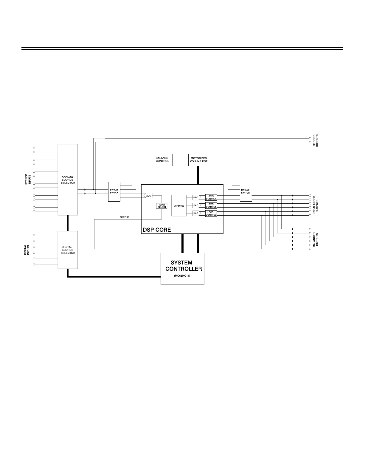
Below is a block diagram of the Bryston SP1. It shows the
signal flow and basic operational structure of the Surround
Processor and Preamplifier.
2
Figure 1: Block Diagram

POWER
The SP1 uses a dual mode electrical power system. In the
electrical power input module located on the right hand side
of the rear panel, adjacent to the IEC power cord socket is a
large computer-style switch that controls the main electrical
power to the unit.This is the ONLY switch that actually
completely turns off all power to the unit. Please see the
illustration below.
When the SP1 is connected to an appropriate AC power
source, and the power switch is switched to the ‘I’ position,
the unit automatically sets itself into a STANDBY power mode,
where-in only the minimum necessary circuitry to respond to
the remote control's power-on command or the momentary
power toggle switch on the front panel are active.
Activating the momentary POWER toggle switch (either up or
down) on the front panel or the POWER button on the
remote immediately takes the unit out of its STANDBY mode
into its normal operating mode.
The presence of AC power to the SP1 is indicated by the
illumination of the front panel LCD display, the illumination of
the LED corresponding to the source you last selected, and
the unit’s LED operating mode indicators.
[NOTE: If your unit's LCD backlight does not illuminate when the SP1 is
plugged into an operating outlet, and switched out of STANDBY mode,
please check to see that the rear panel main power switch {mains switch}
is in the ON position.]
If the SP1 is to be unused for an extended period of time (i.e.
a vacation) it is strongly recommended that it be turned off
using the main power switch on the back panel.
3
Figure 2 – Power Input
Module
CONTROLS AND CONNECTIONS - OVERVIEW
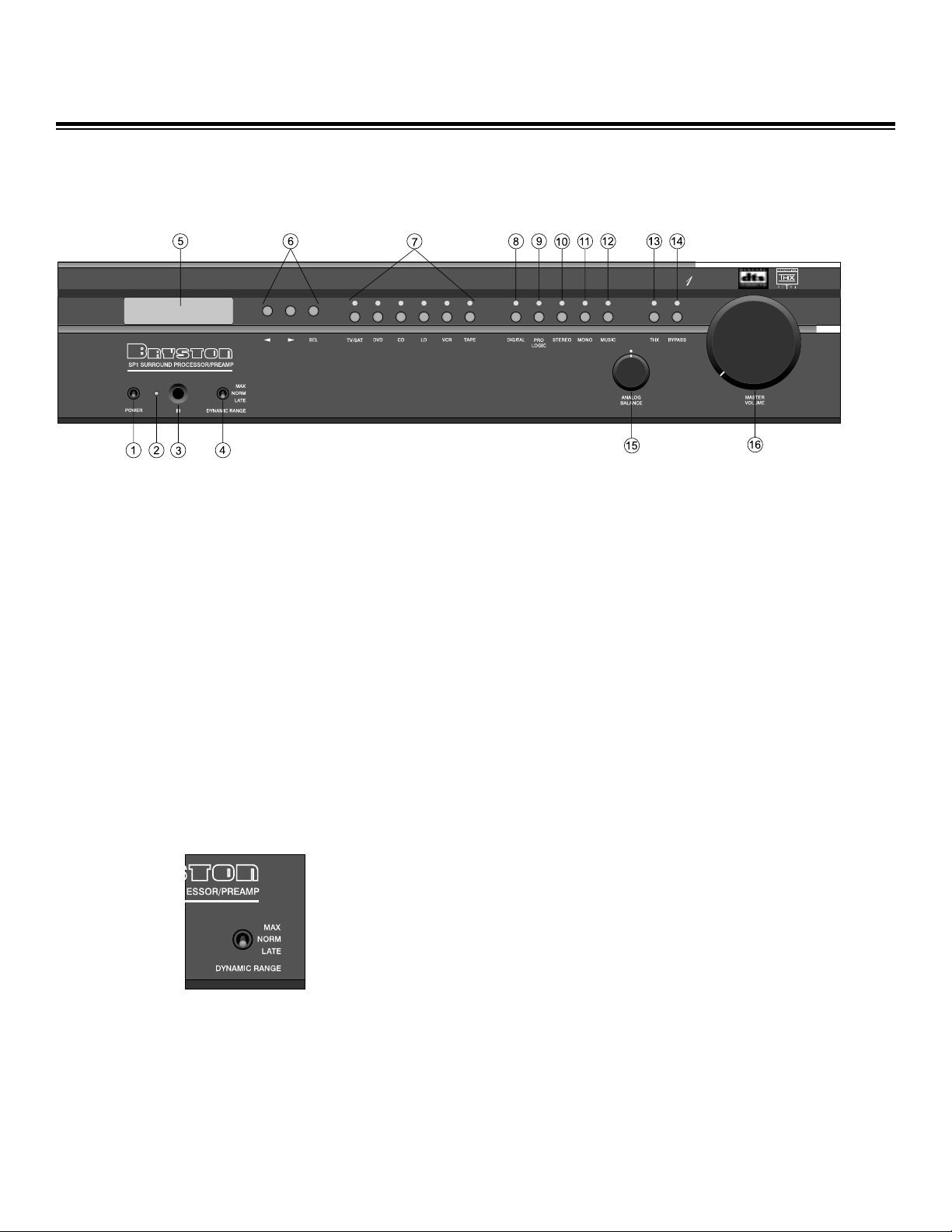
Front Panel Controls and Indicators
When looking at the front panel of the SP1 you will see the
following controls and displays from left to right:
1. Power [Momentary Switch]
Toggling this switch up or down takes the unit in and out of
its' Standby power mode (see above)
2. Standby and (IR) Infrared Activity Indicator
If this LED is continuously bright, it is an indication that the
SP1 is in Standby mode. When the SP1 is powered up, the
LED is OFF, and flashes when a valid IR code is detected.
3. (IR) Infrared Receiver/Sensor for remote control
4. Dynamic Range Control
This three position switch,which will operate only when the
SP1 is in a Dolby Digital mode, permits the adjustment of the
dynamic range (softest sound to loudest sound) of signal
sources producing a Dolby Digital bitstream.
4
Figure 3: Front Panel

A brief explanation follows:
There are two variables built into many Dolby Digital
bitstreams during the encoding process by the program
producers, that can enable decoders like the SP1 to provide
automatic gain control based upon the information supplied
by these data variables.
One of these two variables (labeled Dynrng by Dolby)
provides a type of compression useful for situations such as
late night viewing of programs with a wide dynamic range
(like many action movies).This function can also be used to
provide compression for program material that may require
enhancement of overall intelligibility (such as some older
soundtracks).
Another feature provided by this option is the necessary peak
limiting required avoiding signal overload when "downmixing"
functions are selected.
The second variable (labeled Compr by Dolby) provides
additional peak limiting to allow overall average program level
to be increased.
These two algorithms can provide sufficient overall gain
reduction to allow even high dynamic range soundtracks to
maintain good audibility at low volume levels.
In most cases as an integral part of the Dolby Digital encoding
process, a certain minimum amount of dynamic range
reduction will be automatically included in the bitstream to
ensure safe downmixing.The precise amount of this function
is selected by the program producers, and will to a degree
depend on the contents of the audio channels.
5
USING THE DYNAMIC RANGE CONTROL
For the majority of applications this switch should be placed
and remain in the middle or NORM position.
For late night viewing or at any time you wish to reduce the
overall dynamic range of a program the switch may be set to
the "LATE" (down) position.
If you wish to turn off all of the software's built-in dynamic
range management functions the switch can be set to the
"MAX" (up) position.
NOTE: Caution should be exercised when choosing this option. Many smaller
loudspeaker systems cannot handle the extremely wide range signals
produced in this mode. Overall system volume should be initially set quite
low until you or your dealer are able to determine the maximum safe
setting to avoid damage to your loudspeaker systems or power amplifiers.
5. LCD Display window - contains the two line, black on
green 16 character per line alphanumeric display which
indicates the status and functional mode of the SP1.This
screen is also used during the menu-setup function for
calibration of the SP1 to your system.
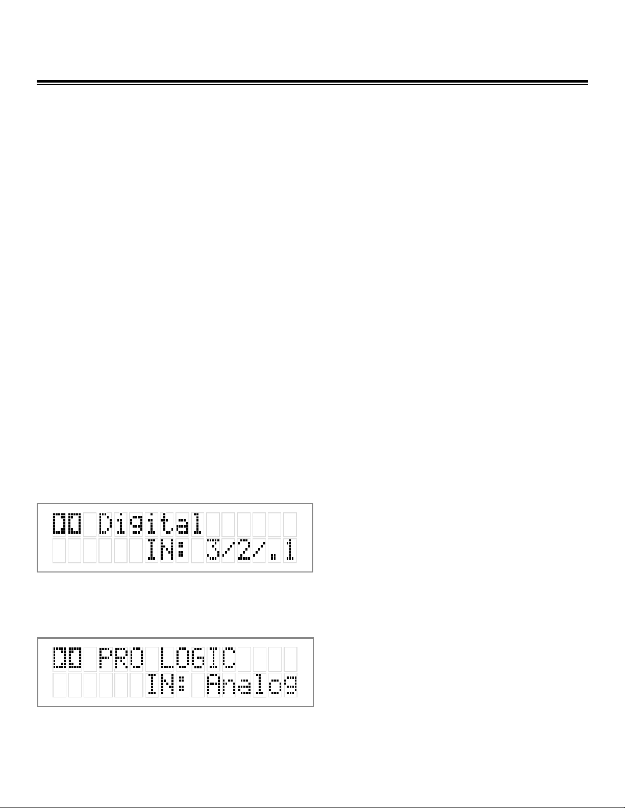
On the first line, the decoding type [Dolby Digital, DTS, ProLogic, Music, etc.] is displayed.A sample screen is shown
below: (FIG 4)
On the second line, the type of signal being detected from the
currently selected input is displayed.A sample screen is
shown below: (Fig 5)
6
Figure 4: Status display showing Dolby
Digital 5.1 channel signal at input
Figure 5: Status display showing analog
input signal and Pro Logic decoding
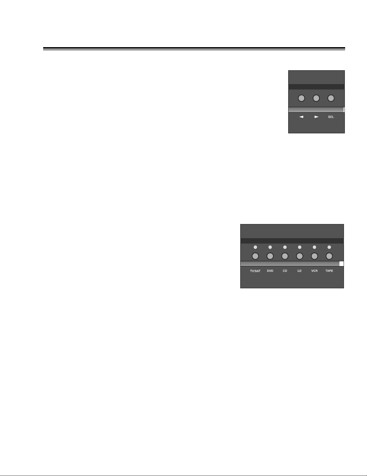
6. Menu Control Buttons
These three buttons labeled "<", ">", and "SEL" (SELECT) are
used to control the menu/setup functions displayed on the
LCD. To enter a menu mode, you can press any one of these
buttons. This will bring up the main menu.
All of the SP1 set-up and calibration operations are done using
these buttons and the LCD screen.
Navigating any menu or sub-menu is done using the two
arrow (< >) buttons. Once the desired submenu or function
is highlighted, pressing "SELECT" will make it the current
menu or function.
To exit a menu, or back up a step use the arrow buttons (< >)
to highlight the 'X' displayed in the lower right hand corner of
the LCD window and press "SELECT".
7. Source Selection Buttons and Indicators
Pressing any one of these buttons will instantly switch the
SP1's analog and digital inputs to read the indicated source.
If the SP1 is in its digital mode, as soon as any input is
selected and switched, the decoder will automatically try to
determine the new bitstream's type and mode.
7
Mode Selection Buttons:
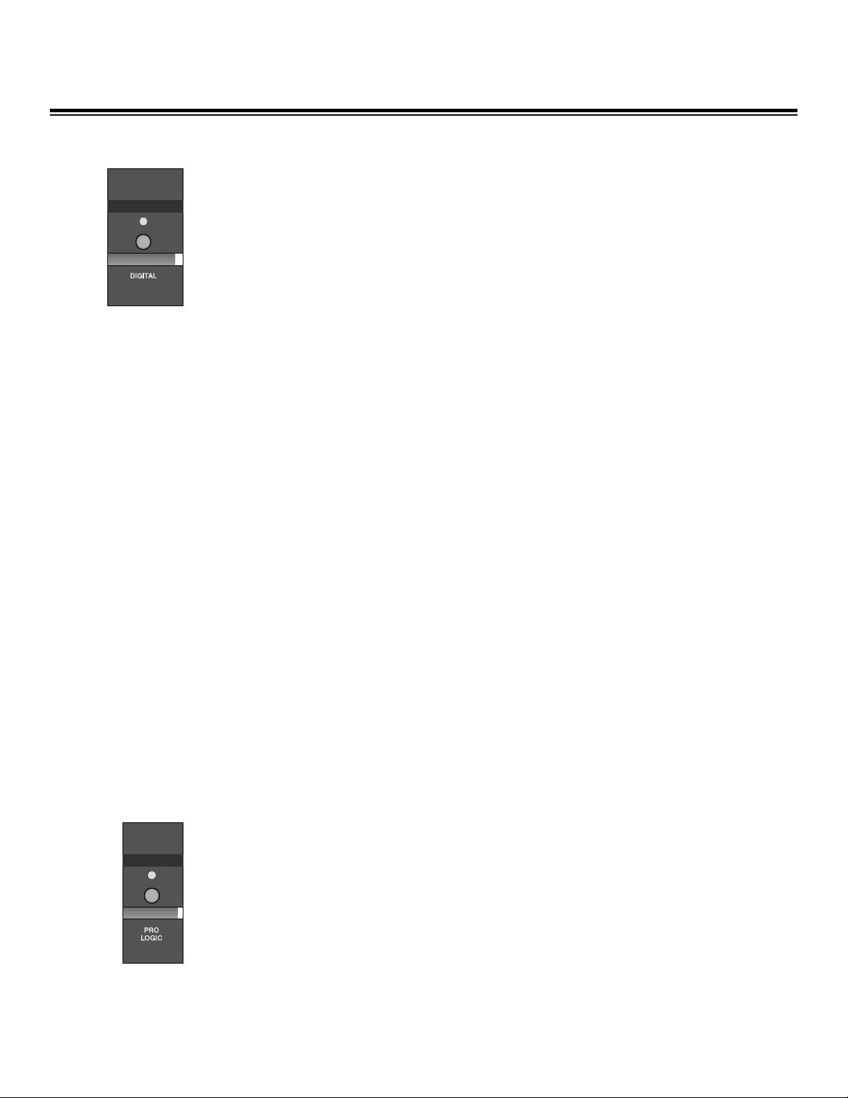
8. Digital Mode and Indicator
This button operates as a three way toggle function. The LED
immediately above the button has two colors - RED and
GREEN, and an OFF mode where it is not illuminated.
When Digital Mode is selected, the decoder will automatically
default to a digital signal for the selected input if one is present.
If a digital signal is present and detected, the SP1 will
automatically determine the type of bitstream and select the
proper decoding mode.The indicator LED will turn green
when this happens.
If NO DIGITAL SIGNAL is detected the SP1 will default back
to the analog input for the selected source.This also
automatically puts the SP1 into its Digital Standby Mode.
When this occurs the LED indicator will turn RED
In this mode, the decoder will continually check the selected
source inputs for the presence of a digital signal.If one is
detected, the SP1 will automatically switch over to the preselected digital operation mode for that source.
To defeat this auto-digital detect mode you must press the
button again. If you do the LED will go OFF.
When this mode of operation is selected the SP1 will look at ONLY
its analog inputs. If a digital signal does appear the SP1 will NOT
recognize it and will remain in its analog only mode until you press
the Digital button again to either select the digital source or place
the SP1 into its auto detect mode as explained above.
9. Analog Pro Logic and Dolby Digital Pro Logic Mode
Switch
In digital mode, this button will produce Pro-Logic decoding
on any 2 channel bitstreams.When this function is operational
the LED will turn green.
If Pro Logic decoding is NOT allowed with the current
bitstream (such as when a DTS signal is present), nothing will
happen when the button is pressed.
In the SP1 's analog mode, this button will produce standard
Pro Logic format decoding on the selected analog input(s).
8
 Loading...