

Bryston C Series 875HT, 875HT Owner's Manual

875HT
OWNER’S
MANUAL

IMPORTANT SAFETY INSTRUCTIONS
The lightning flash with arrowhead symbol within an equilateral triangle, is intended to alert the user to the presence of un-insulated
“dangerous voltage “ within the product’s enclosure that may be of sufficient magnitude to constitute a risk of electric shock to
persons.
1. Read these instructions.
2. Keep these instructions.
3. Heed all warnings.
4. Follow all instructions.
5. Do not use this apparatus near water.
6. Clean only with dry cloth.
7. Do not block any ventilation openings. Install in accordance with the manufacturer’s instructions.
8. Do not install near any heat sources such as radiators, heat registers, stoves, or other apparatus (including amplifiers) that produce heat.
9. Do not defeat the safety purpose of the polarized or grounding-type plug. A polarized plug has two blades with one wider than the other. A
10. Protect the power cord from being walked on or pinched particularly at plugs, convenience receptacles, and the point where they exit from the
11. Only use attachments/accessories specified by the manufacturer.
12. Use only with the cart, stand, tripod, bracket, or table specified by the manufacturer, or sold with the apparatus. When a car t is
13. Unplug this apparatus during lightning storms or when unused for long periods of time.
14. Refer all servicing to qualified service personnel. Servicing is required when the apparatus has been damaged in any way, such as power-
WARNING: TO REDUCE THE RISK OF FIRE OR ELECTRIC SHOCK, DO NOT EXPOSE THIS APPARATUS TO RAIN OR MOISTURE.
DO NOT EXPOSE THIS EQUIPMENT TO DRIPPING OR SPLASHING AND ENSURE THAT NO OBJECTS FILLED WITH LIQUIDS, SUCH AS VASES, ARE
PLACED ON THE EQUIPMENT.
TO COMPLETELY DISCONNECT THIS EQUIPMENT FROM THE AC MAINS, DISCONNECT THE POWER SUPPLY CORD PLUG FROM THE AC
RECEPTACLE.
THE MAINS PLUG OF THE POWER SUPPLY CORD SHALL REMAIN READILY OPERABLE.
The exclamation point within an equilateral triangle is intended to alert the user to the presence of important operating and maintenance
(servicing) instructions in the literature accompanying the product.
grounding type plug has two blades and a third grounding prong. The wide blade or the third prong are provided for your safety. If the provided plug does not fit into your outlet, consult an electrician for replacement of the obsolete outlet.
apparatus.
used use caution when moving the cart/apparatus combination to avoid injury from tip-over.
supply cord or plug is damaged, liquid has been spilled or objects have fallen into the apparatus, the apparatus has been exposed to rain or
moisture, does not operate normally, or has been dropped.
BRYSTON LIMITED WARRANTY
Bryston analog audio circuits are warranted to be free from manufacturing defects for twenty (20) years from the original date of manufacture. The
warranty includes par ts and labour.
Bryston Digital circuits and cables are warranted for five years from the original date of manufacture. The warranty includes parts and labour.
Bryston products having motorized moving parts, excluding motorized volume controls, are warranted for three years from the original date of manufacture. The warranty includes parts and labour.
Bryston will remedy the problem by repair or replacement, as we deem necessary, to restore the product to full performance. Bryston will pay shipping costs one way (usually the return portion) during the first three years of warranty coverage.
In the event of a defect or malfunction, contact Bryston’s repair centers for return authorization. Products must be returned using original packaging
material only. Packing material may be purchased from Bryston if necessary. This warranty is considered void if the defect, malfunction or failure of the
product or any component part was caused by damage (not resulting from a defect or malfunction) or abuse while in the possession of the customer.
Tampering by persons other than factory authorized service personnel or failure to fully comply with Bryston operating instructions voids the warranty.
This warranty gives you specific legal rights and you may also have other rights which may vary from province to province and country to country.
As of 2006-02-22 Bryston will only warranty Bryston products purchased through authorized Bryston dealers. Bryston products with a date code
of 0608 or higher (date code format is “yyww”, where “yy” is the two least significant digits of the year and “ww” is the week of the year) must be
accompanied by a copy of the bill-of-sale from a Bryston authorized dealer to qualify for warranty service. The warranty is transferable from the original
owner to a subsequent owner as long as a copy of the bill-of-sale from the original authorized Bryston dealer accompanies the re-sale. The copy of the
bill of sale to any subsequent owner need ONLY include the Name of the Bryston Authorized Dealer and the Model and Serial number of the Bryston
product The warranty will only be honored in the country of the original purchase unless otherwise pre-authorized by Bryston.
BRYSTON SERVICE in CANADA: BRYSTON SERVICE in the USA:
Postal address: P.O. BOX 2170, Stn. Main
PETERBOROUGH, ONTARIO
CANADA K9J 7Y4
Courier address: 677 NEAL DRIVE
PETERBOROUGH, ONTARIO
CANADA K9J 6X7
PHONE: 705-742-5325
FAX: 705-742-0882
E-mail: cdnser@bryston.ca
79 COVENTRY ST., Suite 5
NEWPORT, VERMONT
U.S.A. 05855-2100
PHONE: 802-334-1201
FAX: 802-334-6658
E-mail: usaser@bryston.ca
BRYSTON SERVICE outside Canada and the USA:
contact your local distributor or
CHECK OUR WEB SITE: www.bryston.ca
E-MAIL BRYSTON DIRECTLY: cdnser@bryston.ca
FAX BRYSTON DIRECTLY: 01-705-742-0882
PHONE BRYSTON DIRECTLY: 01-705-742-5325

875HT EIGHT CHANNEL POWER AMPLIFIER
Table of Contents
Important Safety Instructions
General Introduction Page 1
Introduction
Description
Shipping Box & Packing Materials
Installation
Wiring the 875HT
Front Panel Page 2
Power Switch
LED Indicators
Fuses
875HT Rear Panel Input/Output Connections Page 3
Single Ended Input Connector
Balanced Input Connector
Balanced versus UnBalanced Inputs
Input Select Switch
Stereo/MonoSwitch
Output Binding Posts
875HT Rear Panel Input/Output Connections contd. Page 4
Ratings Label
Power Inlet
Power-Up Connector
Typical 5.1Home Theatre Setup Page 5
Typical 7.1Home Theatre Setup Page 6
High Power 7.1 Home Theatre Setup Page 7
Block Diagram Page 8
AC Power Control Page 9
External Control Voltage Power Up
AC Power Input
Technical Specifications Page 10
Important Warranty Information Back Cover

875HT EIGHT CHANNEL POWER AMPLIFIER
1
INTR
ODUCTION
Thank you for choosing the 875 Eight Channel Power Amplifier. Bryston welcomes any suggestions you may have, or
comments regarding the operation of your amplifier. We consider you, our customer, to be Bryston’s most important
resource, and your opinion is very much appreciated.
DESCRIPTION
The 875HT is a modular multi-channel audio power amplifier design of 8 x 75 Watts per channel. It is essentially 4 stereo
amplifiers. Each stereo pair selects from balanced or single ended inputs, and each stereo pair may be bridged to form a
single higher power amplifier channel. The gain of the balanced input is 23dB and the single ended input is 29dB.
The power up sequence of the 875HT may be controlled from a 12v control voltage. The 875 uses ‘soft start’ power control circuitry to eliminate high inrush currents when A/C power is applied.
WARRANTY (see back page for details )
SHIPPING BOX & PACKING MATERIAL
Please keep the original shipping box and all packing material. This will ensure the amplifier is protected in future transport. In the unlikely event you have a problem and must return it for service you must use the proper packing material.
Ship the amplifier only in the original packing material, as the unit is not insurable by carriers otherwise.
INSTALLATION
The most important installation consideration is ventilation. The 875 series amplifiers are a convection-cooled.
Unrestricted air-flow across its heat sinks is a must. For this reason do not install anything directly above it. Allow 3.5” (2u)
to 5” (3u) inches of space above and to the sides of this amplifier. Do not install directly above other heat generating equipment. Any 875 channels thermally shutting down during operation indicates insufficient cooling, and a remedy must be
found for cooling the amplifier. Provide a minimum 6” space to the rear of the 875 for ventilation and dressing cables to
and from the amplifier.
Never operate the
875 in a vertical position.
WIRING THE 875HT (also see rear panel description )
Speaker wires should be as short as practical. Use quality wire, and if runs are more than 3 meters use at least 12 gauge
wire. The speaker binding posts will accept wire up to 3 gauge in size. Bryston can custom build cables for your application.
P
A/C power:
Before plugging in the power cord be sure your 875 is specified for the correct A/C voltage for your locality. The
voltage is listed by the power input connector. Never lift the safety ground to the amplifier or remove the ground pin
from the plug.
P
Power line conditioners:
The 875’s performance will not be improved by the use of power line conditioners. In fact most of the time they
restrict the flow of current in the power line to the amplifier thereby reducing performance at high output levels.
875HT EIGHT CHANNEL POWER AMPLIFIER
2
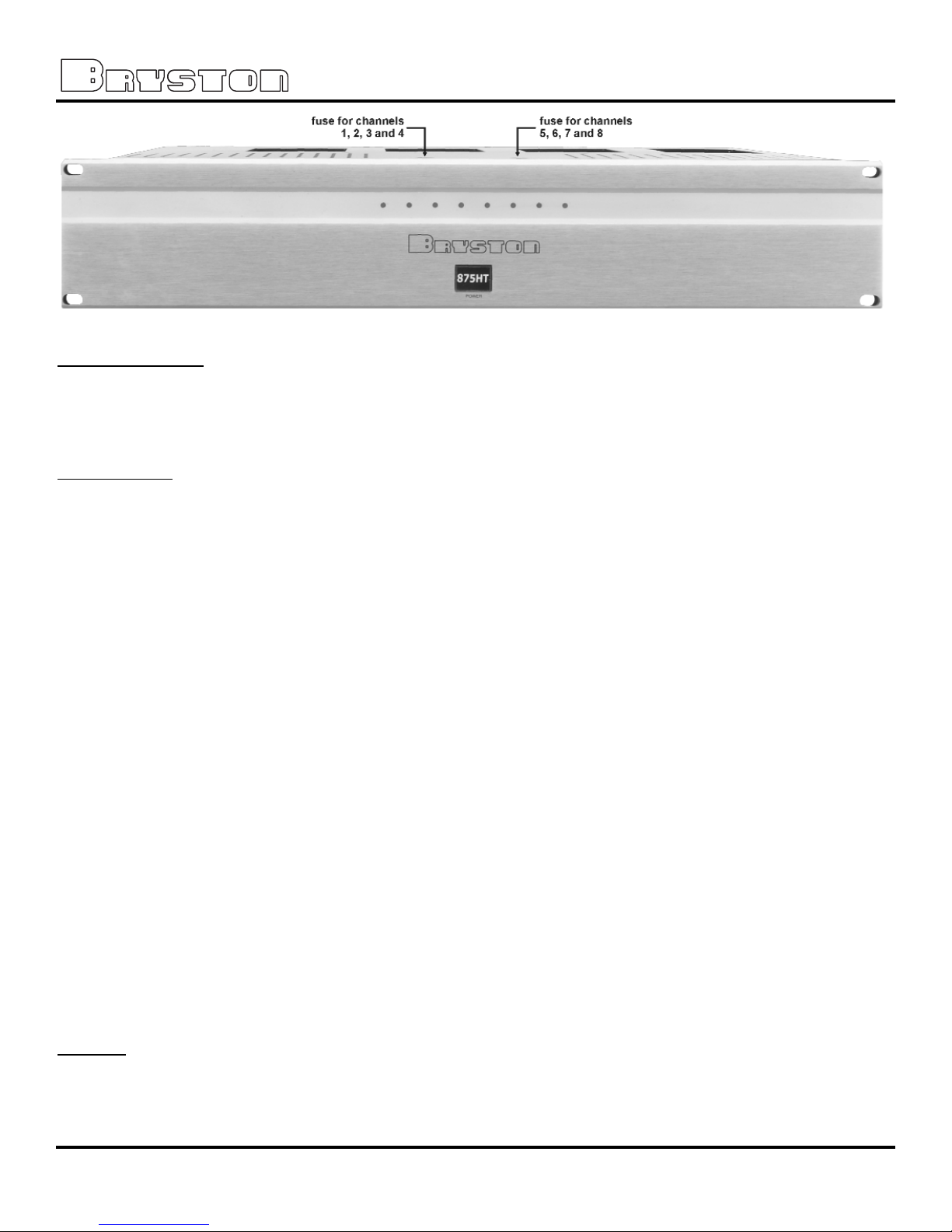
FRONT PANEL OF 875HT-Silver:
FRONT PANEL
POWER switch
The front panel label '875HT POWER’ is a switch used to apply or remove A/C line power to the 875 soft start circuitry.
Push the switch and the 875 will initiate the start up sequence. The switch cap remains indented when circuits are on.
Push the switch again the 875 will initiate the power off sequence.
LED Indicators:
Each 875 channel has a single multi-colour LED indicator to monitor the following conditions:
P
Unlit LED: no power
The 875 channel led when unlit indicates no A/C mains power is present at the channel. If all channel led indicators
are unlit the 875 probably needs only to be powered on. A group of 4 leds not lighting possibly indicates blown group
fuse. When checking fuses, unplug the power cord. Use only the specified fuses for your operating voltage.
See page 6 for the fuse locations.
P
Red LED: muted.
Each channel normally mutes momentarily during power up and power down sequences.
P
Green LED: normal operation
P
Flashing Red LED: Clipping
Clipping occurs when the channel output level no longer can follow the level increase at the input (Over driven input
condition). When a 875 channel is driven into clipping the channel led will change from green to red then back to
green when the level is reduced ( Flashing Red ). Momentary clipping can be tolerated, however it indicates that
maximum un-distorted power has been surpassed and potential speaker damage may result if over load conditions
persist. Any amplifier that is constantly operated into clipping indicates a more powerful amplifier is needed for that
application.
P
Orange LED: Thermal Shutdown
The 875 channel has thermal shutdown circuitry to prevent damage due to over heating. Should thermal shutdown
occur, the both stereo channels will mute, and the channel leds will turn orange indicating this condition. When the
channels have cooled to a safe operating condition the channels will return to normal operation. Persistent Thermal
shutdown indicates steps need to be taken to increase airflow across the channels heat sink. (Also see installation
section on ventilation).
FUSES
There are two fuse holders located at the front edge of the top panel. When checking fuses, power down the unit and
disconnect the power cord. Use only the specified fuses as indicated on the label located between the two fuse holders
on the top panel. See photo at top of page.
 Loading...