

Page 1

Single-Package Rooftop Products with Energy-Saving Features
• Direct Spark Ignition
• Low Sound Levels
• Up to 81% AFUE
• 12 SEER
FEATURE/BENEFITS
One-piece heating and cooling unitswithlowsoundlevels,easy
installation, low maintenance, and dependable performance.
EASY INSTALLATION — Factory-assembled package is a
compact, fully self-contained, combination gas heating/electric
cooling unit that is pre-wired, pre-piped, and pre-charged for
minimum installation expense.
These units are available in a variety of standard and optional
heating/cooling size combinations with voltage options to meet
residential and light commercial requirements. Units are lightweight and install easily on a rooftop or at ground level. The
high tech composite basepan eliminates rust problems associated with ground level applications.
CONVERTIBLE DUCT CONFIGURATION — Unit is designed
for easy use in either downflow or horizontal applications. Each
unit is easily converted from horizontal to downflow with addition
of two accessory duct covers.
EFFICIENT OPERATION
High-Efficiency Design with SEER (Seasonal Energy Effi-
ciency Ratios) of 12.0 and AFUE (Annual Fuel Utilization Efficiency) rating as high as 81%.
Energy-Saving, Direct Spark Ignition saves gas by operating
only when the room thermostat calls for heating. Standard units
are furnished with natural gas controls. A low cost field-installed
kit for propane conversion is available for all units.
All Units meet the California maximum oxides of nitrogen
(NOx) emission requirements when accessory kit is used.
DURABLE, DEPENDABLE COMPONENTS
Compressors are designed for high efficiency. Each compres-
sor is hermetically sealed against contamination to help promote longer life and dependable operation. Each compressor
also has vibration isolation to provide quieter operation. All
compressors have internal high pressure and overcurrent
protection.
Monoport Inshot Burners produce precise air-to-gas mixture,
which provides for clean and efficient combustion. The large
monoport on the inshot (or injection type) burners seldom, if
ever, requires cleaning. All gas furnace components are accessible in one compartment.
Turbo-tubular™ Heat Exchangers are constructed of aluminized steel for corrosion resistance and optimum heat transfer
for improved efficiency. The tubular design permits hot gases to
make multiple passes across the path of the supply air.
In addition, dimples located on the heat exchanger walls force
the hot gases to stay in close contact with the walls, improving
heat transfer.
Direct-Drive Multi-Speed, PSC (Permanent Split Capacitor)
Blower Motor is standard on all 583A models.
Direct-Drive, PSC Condenser-Fan Motors are designed to
help reduce energy consumption and provide for cooling operation down to 40 F outdoor temperature. MotormasterT II low ambient kit is available as a field-installed accessory.
Corporate Thermostats include the Time GuardT II anti-short
cycle protection circuitry. If an Original Equipment Manufacture
(OEM) thermostat is used the Time Guard II field-installed antishort cycle kit must be used.
Refrigerant System is designed to provide dependability. Liquid refrigerant strainers are used to promote clean, unrestricted
operation. Each unit leaves the factory with a full refrigerant
charge. Refrigerant service connections make checking operating pressures easier.
Evaporator and Condenser Coils are computer-designed for
optimum heat transfer and cooling efficiency. The evaporator
coil is fabricated from copper tube and aluminum fins and is located inside the unit for protection against damage. The condenser coil is internally mounted on the top tier of the unit. A
FIOP (Factory-Installed Option) metal louvered grille is available
on all models. Copper fin coils and pre-coated fin coils are available from the factory by special order. These coils are recommended in applications where aluminum fins are likely to be
damaged due to corrosion. They are ideal for seacoast
applications.
Low Sound Ratings ensure a quiet indoor and outdoor environment with sound ratings as low as 7.2 bels. (See page 3.)
Easy to Service Cabinets provide easy single-panel accessibility to serviceable components during maintenance and installation. The basepan with integrated drain pan provides easy
ground level installation with or without a mounting pad. Convenient handholds are provided to manipulate the unit on the
UNIT 583A
SINGLE-PACKAGE
GAS HEATING/ELECTRIC
COOLING UNITS
Model 583A
Sizes 024-060
2 to 5 Nominal Tons
Form No. PDS 583A.24.1
Page 2

jobsite. A nesting feature ensures a positive basepan to roof
curb seal when the unit is roof mounted. A convenient
3
⁄4-in.
wide perimeter flange makes frame mounting on a rooftop easy.
Downflow Operation is easily provided in the field to allow ver-
tical ductwork connections. The basepan utilizes knockout style
seals on the bottom openings to ensure a positive seal in the
horizontal airflow mode.
Integrated Gas Control (IGC) Board provides safe and efficient control of heating and simplifies troubleshooting through
its built-in diagnostic function.
Cabinets are constructed of heavy-duty, phosphated, zinccoated prepainted steel capable of withstanding 500 hours in
salt spray. Interior surfaces of the evaporator/heat exchanger
compartment are insulated with cleanable semi-rigid insulation
board, which keeps the conditioned air from being affected by
the outdoor ambient temperature and provides improved indoor
air quality. (Conforms to American Society of Heating, Refrigeration and Air Conditioning Engineers No. 62P.) The sloped
drain pan minimizes standing water in the pan.
TABLE OF CONTENTS
Page
Features/Benefits ................................1,2
Model Number Nomenclature ........................3
ARI Capacities ..................................3,4
Physical Data ....................................5
Options and Accessories ..........................6,7
Base Unit Dimensions.............................8,9
Accessory Dimensions ............................10
Selection Procedure ..............................11
Performance Data ..............................12-17
Typical Piping and Wiring ..........................18
Application Data .................................19
Electrical Data ...................................20
Typical Wiring Schematics ........................21-23
Controls ........................................24
Guide Specifications ............................25,26
2
Page 3
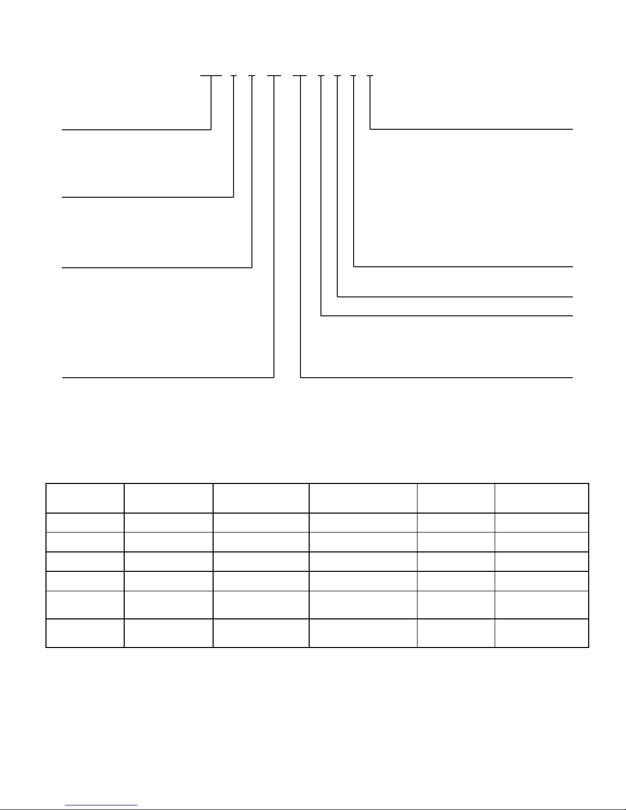
MODEL NUMBER NOMENCLATURE
CU — Copper
ARI* CAPACITIES
COOLING CAPACITIES AND EFFICIENCIES
UNIT
583A
NOMINAL
TONS
STANDARD
CFM
NET COOLING
CAPACITIES
(Btuh)
SEER†
SOUND
RATINGS**
(Bels)
024040
2 800 24,000 12.0 7.2
024060
030040
2
1
⁄
2
1000 30,000 12.0 7.2
030060
036060
3 1200 35,000 12.0 7.4
036090
042060
3
1
⁄
2
1400 42,000 12.0 7.4
042090
048090
4 1600 48,000 12.0 8.0048115
048130
060090
5 1750 58,000 12.0 7.8060115
060130
LEGEND
Bels — Sound Levels (1 bel = 10 decibels)
db — Dry Bulb
SEER — Seasonal Energy Efficiency Ratio
wb — Wet Bulb
*Air Conditioning & Refrigeration Institute.
†Rated in accordance with U.S. Government DOE (Department of
Energy) test procedures and/or ARI Standard 210/240-94.
**Tested in accordance with ARI Standard 270-95 (not listed in ARI).
NOTES:
1. Ratings are net values, reflecting the effects of circulating fan heat.
Ratings are based on:
Cooling Standard: 80 F db, 67 F wb indoor entering-air temperature
and 95 F db outdoor entering-air temperature.
2. Before purchasing this appliance, read important energy cost and
efficiency information available from your retailer.
Option Code
A – Base Unit Wire Grille
H–Base Unit Louvered Grille
J–Unit with Wire Grille and Vinyl-Coated
Condenser Coil
K–Unit with Louvered Grille and Vinyl-Coated
Condenser Coil
L–Unit with Wire Grille and CU/CU
Condenser Coil
M– Unit with Wire Grille and CU/CU Evaporator and
CU/CU Condenser Coil
N–Unit with Louvered Grille and CU/CU
Condenser Coil
P–Unit with Louvered Grille and CU/CU Evaporator
and CU/CU Condenser Coil
583A N W 024 040 A A A D
Model Number
583A – Single Package
Gas Heating/
Electric Cooling Unit
Nominal Cooling Capacity
024 – 2.0 Tons
030 – 2.5 Tons
036 – 3.0 Tons
042 – 3.5 Tons
048 – 4.0 Tons
060 – 5.0 Tons
Series
A–Original
Heat Input Size (Btuh)
040 – 40,000
060 – 60,000
090 – 90,000
115 – 115,000
130 – 130,000
Electrical Supply
N–208/230-1-60
P–208/230-3-60
E–460-3-60
Fuel and Controls
W–Natural Gas
P–Propane Gas
Motor (Not an Option)
Brand Name
3
Page 4
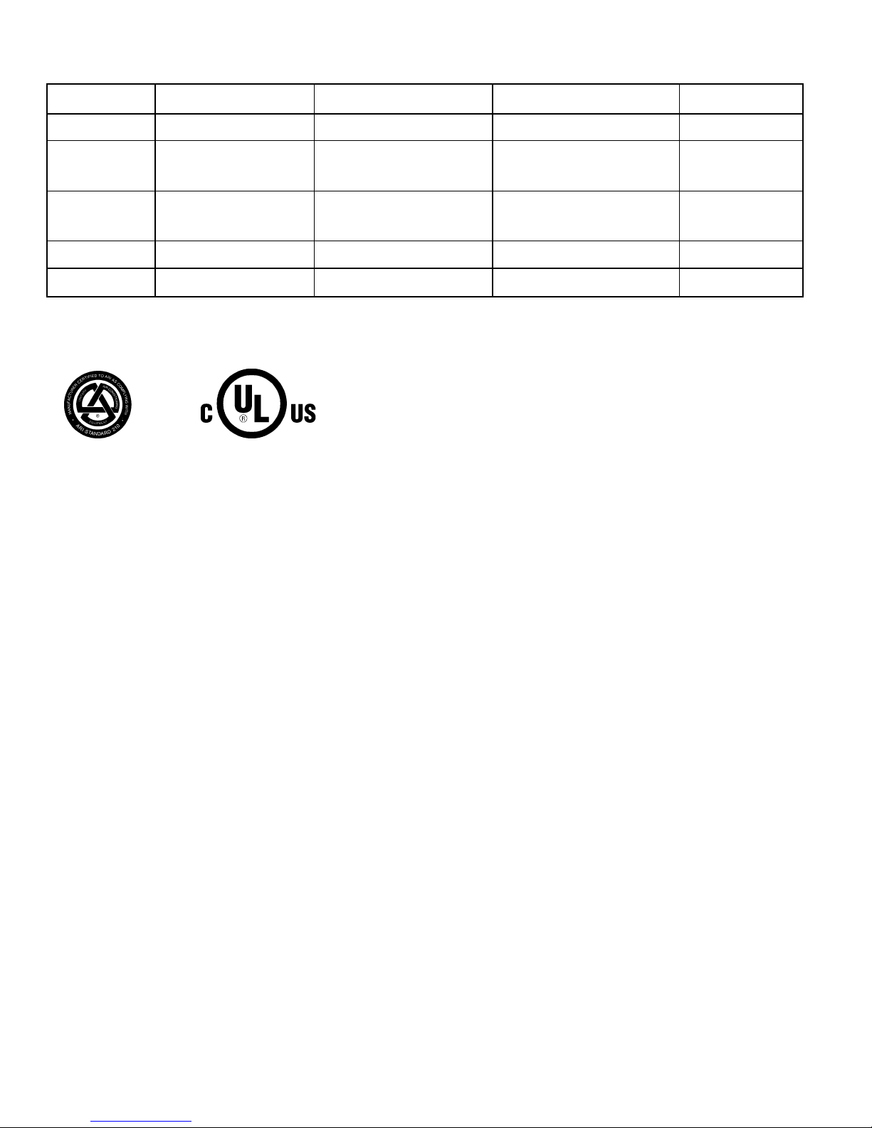
ARI* CAPACITIES (cont)
HEATING CAPACITIES AND EFFICIENCIES
UNIT
583A
HEATING INPUT
(Btuh)
OUTPUT CAPACITY
(Btuh)
TEMPERATURE RISE
RANGE (°F)
AFUE (%)
024040
40,000 32,040 20-50
80.1
030040 80.0
024060
60,000
47,040 35-65 78.4
030060 47,040 35-65 80.1
036060 47,220 25-55 78.7
042060 47,220 15-45 78.7
036090 88,000 71,910 45-75 79.9
042090 90,000 71,910 35-65 79.9
048090 90,000 70,740 25-55 78.6
060090 90,000 70,740 25-55 78.6
048115
115,000 93,265 35-65 81.1
060115
048130
130,000 104,390 40-70 80.3
060130
LEGEND
AFUE — Annual Fuel Utilization Efficiency
NOTE: Before purchasing this appliance, read important energy cost and efficiency information available from your retailer.
4
Page 5
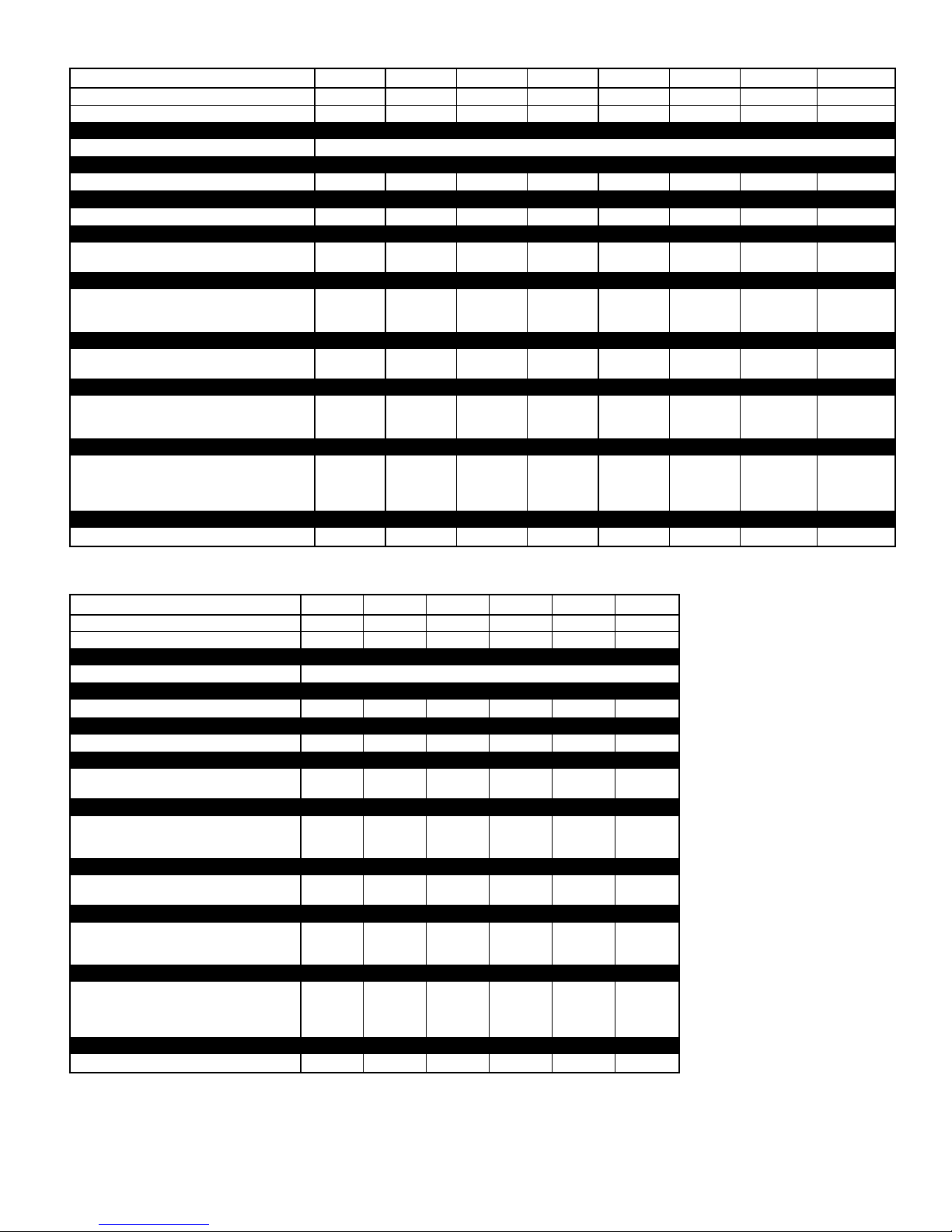
PHYSICAL DATA
UNIT SIZE 583A 024040 024060 030040 030060 036060 036090 042060 042090
NOMINAL CAPACITY (ton) 222
1
⁄
2
2
1
⁄
2
333
1
⁄
2
3
1
⁄
2
OPERATING WEIGHT (lb) 290 290 313 313 321 321 382 382
COMPRESSORS Scroll
Quantity 1
REFRIGERANT (R-22)
Quantity (lb) 3.4 3.4 4.4 4.4 5.2 5.2 6.4 6.4
REFRIGERANT METERING DEVICE Acutrol™ Device
Orifice ID (in.) .034 .034 .030 .030 .032 .032 .034 .034
CONDENSER COIL
Rows...Fins/in. 1...17 1...17 1...17 1...17 2...17 2...17 2...17 2...17
Face Area (sq ft) 9.1 9.1 12.7 12.7 9.1 9.1 12.3 12.3
CONDENSER FAN
Nominal Cfm 2350 2350 2350 2350 2350 2350 3300 3300
Diameter (in.) 22 22 22 22 22 22 22 22
Motor Hp (Rpm)
1
⁄8(825)1⁄8(825)1⁄8(825)1⁄8(825)1⁄8(825)1⁄8(825)1⁄4(1100)1⁄4(1100)
EVAPORATOR COIL
Rows ...Fins/in. 3...15 3...15 3...15 3...15 3...15 3...15 3...15 3...15
Face Area (sq ft) 3.1 3.1 3.1 3.1 3.7 3.7 4.7 4.7
EVAPORATOR BLOWER
Nominal Airflow (Cfm) 800 800 1000 1000 1200 1200 1400 1400
Size (in.) 10x10 10x10 10x10 10x10 11x10 11x10 11x10 11x10
Motor (Hp)
1
⁄
4
1
⁄
4
1
⁄
4
1
⁄
4
1
⁄
2
1
⁄
2
3
⁄
4
3
⁄
4
FURNACE SECTION*
Burner Orifice No. (Qty...Drill Size)
Natural Gas
2...44 2...38 2...44 2...38 2...38 3...38 2...38 3...38
Burner Orifice No. (Qty...Drill Size)
Liquid Propane
2...50 2...46 2...50 2...46 2...46 3...46 2...46 3...46
RETURN-AIR FILTERS (in.)†
Throwaway 20x20 20x20 20x20 20x20 20x24 20x24 24x30 24x30
UNIT SIZE 583A 048090 048115 048130 060090 060115 060130
NOMINAL CAPACITY (ton) 444555
OPERATING WEIGHT (lb) 421 421 421 468 468 468
COMPRESSORS Scroll
Quantity 1
REFRIGERANT (R-22)
Quantity (lb) 7.2 7.2 7.2 8.1 8.1 8.1
REFRIGERANT METERING DEVICE Acutrol Device
Orifice ID (in.) .034 .034 .034 .032 .032 .032
CONDENSER COIL
Rows...Fins/in. 2...17 2...17 2...17 2...17 2...17 2...17
Face Area (sq ft) 12.3 12.3 12.3 16.4 16.4 16.4
CONDENSER FAN
Nominal Cfm 3300 3300 3300 3300 3300 3300
Diameter (in.) 22 22 22 22 22 22
Motor Hp (Rpm)
1
⁄4(1100)1⁄4(1100)1⁄4(1100)1⁄4(1100)1⁄4(1100)1⁄4(1100)
EVAPORATOR COIL
Rows...Fins/in. 4...15 4...15 4...15 4...15 4...15 4...15
Face Area (sq ft) 4.7 4.7 4.7 4.7 4.7 4.7
EVAPORATOR BLOWER
Nominal Airflow (Cfm) 1600 1600 1600 1750 1750 1750
Size (in.) 11x10 11x10 11x10 11x10 11x10 11x10
Motor (Hp)
3
⁄
4
3
⁄
4
3
⁄
4
1.0 1.0 1.0
FURNACE SECTION*
Burner Orifice No. (Qty...Drill Size)
Natural Gas
3...38 3...33 3...31 3...38 3...33 3...31
Burner Orifice No. (Qty...Drill Size)
Liquid Propane
3...46 3...42 3...41 3...46 3...42 3...41
RETURN-AIR FILTERS (in.)†
Throwaway 24x30 24x30 24x30 24x30 24x30 24X30
*Based on altitude of 0 to 2000 feet.
†Required filter sizes shown are based on the larger of the ARI (Air Conditioning
and Refrigeration Institute) rated cooling airflow or the heating airflow velocity of
300 ft/min for throwaway type or 450 ft/min for high-capacity type. Air filter pressure
drop for non-standard filters must not exceed 0.08 in. wg.
5
Page 6
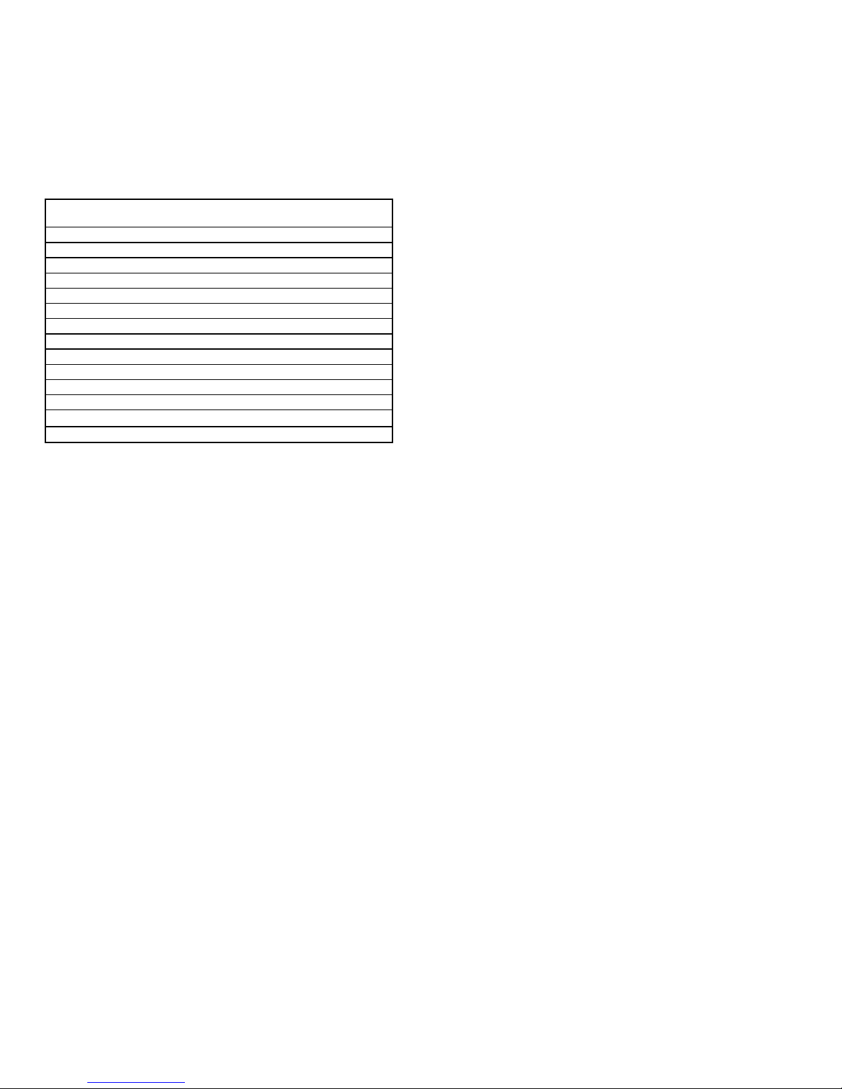
OPTIONS AND ACCESSORIES
FACTORY-INSTALLED OPTIONS
Louvered Grille provides hail and vandalism protection. See
model number nomenclature for louvered grille options.
Coil Options include copper/copper and vinyl-coated construc-
tion for refrigerant coils. Units are shipped standard with copper
tube/aluminum fin construction. See model number nomenclature for coil options.
FIELD-INSTALLED ACCESSORIES
Economizer with Solid-State Controls and Barometric
Relief Dampers
Manual Air Damper (25% open)
Filter Rack
Flat Roof Curbs (8-in. and 14-in.)
Square-to-Round Duct Transition Kit
Thermostats
Controls Upgrade Kit
Crankcase Heater
Compressor Hard Start Kit (for use on single-phase units only)
LP Conversion Kit
High Altitude Kit
Low NO
x
Kit
Low Ambient Kit (MotormasterT II Control)
Solid-State Time GuardT II Device
Duct Conversion Kit (Horizontal to Vertical)
Economizer with Solid-State Controls and Barometric Relief Dampers includes filter racks and provide outdoor air during
cooling and reduce compressor operation.
Manual Outside Air Damper includes hood and filter rack with
adjustable damper blade for up to 25% outdoor air.
Flat Roof Curbs in both 8 in. and 14 in. sizes are available for
roof mounted applications.
Square-to-Round Duct Transition Kit enables 024-048 size
units to be fitted to 14 in. round ductwork.
Compressor Hard Start Kit assists compressor start-up by
providing additional starting torque on single-phase units and
prolongs compressor motor life.
Duct Conversion Kit consists of 2 duct covers to be placed
over the horizontal supply and return duct openings when the
unit is converted for downshot applications.
Thermostats provide control for the system heating and cooling
functions. Thermostat models are available in both programmable and non-programmable versions.
Controls Upgrade Kit supplies high and low pressure safety
protection and protects the unit from operating in unsuitable
conditions.
Crankcase Heater provides anti-floodback protection for lowload cooling applications.
LP (Liquid Propane) Conversion Kit allows for conversion
from natural gas to liquid propane fuel.
Low NO
x
Kit for use with units being installed in California Air
Quality Management Districts which require NO
x
emissions of
40 nanograms/joule or less.
Low-Ambient Kit (Motormaster II Control) allows the use
of mechanical cooling down to outdoor temperatures as low
as 0° F.
Solid-State Time Guard II Device provides short-cycling protection for the compressor. Not required with corporate electronic thermostats.
Filter Rack features easy installation, serviceability, and highfiltering performance for vertical applications.
High Altitude Kit is for use at 2001 to 6000 ft above sea level.
Kit consists of natural gas orifices that compensate for gas heat
operation at high altitude.
6
Page 7
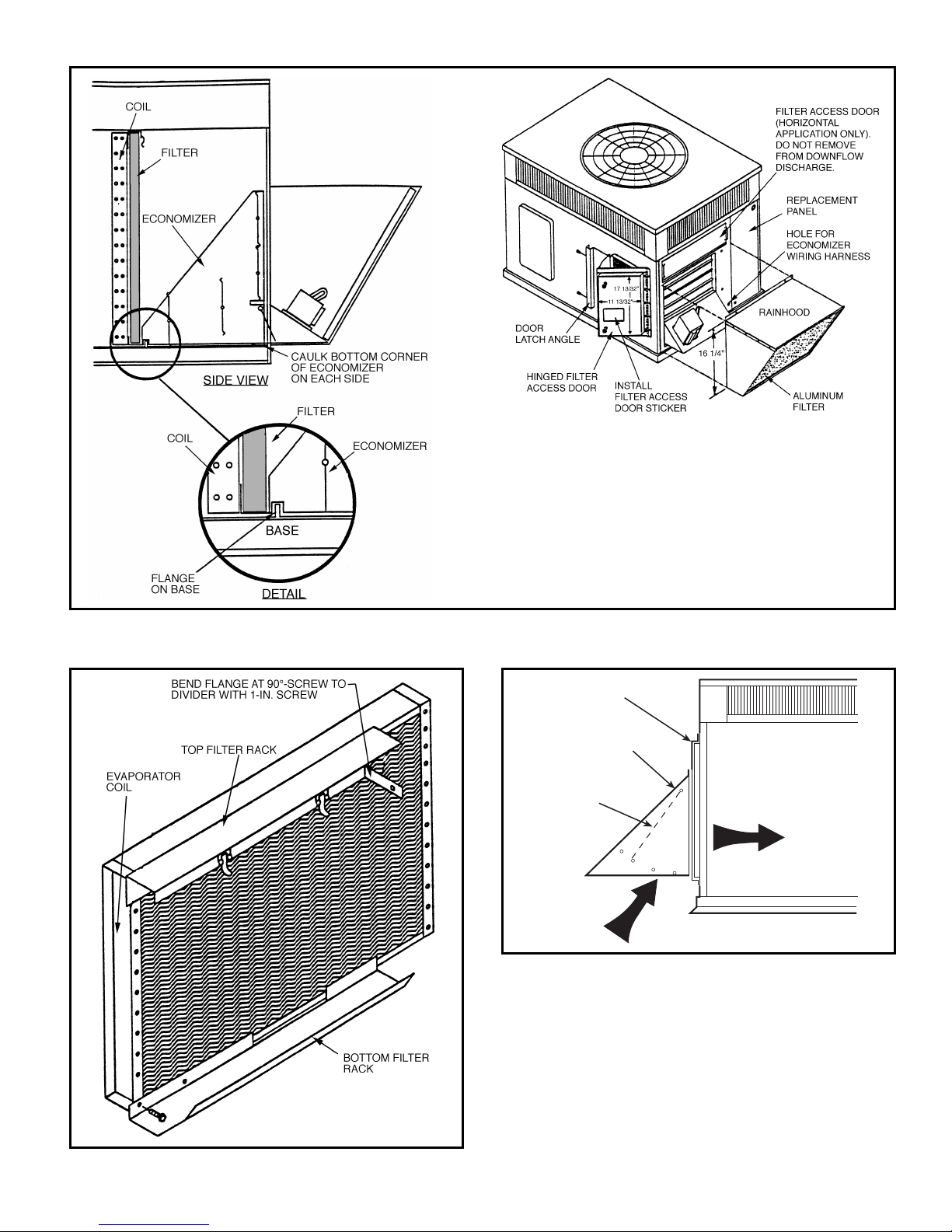
OPTIONS AND ACCESSORIES (cont)
Economizer
Filter Rack
Manual Outside Air Damper
DAMPER
BLADE
MANUAL OUTSIDE
AIR HOOD
REPLACEMENT
PANEL
7
Page 8
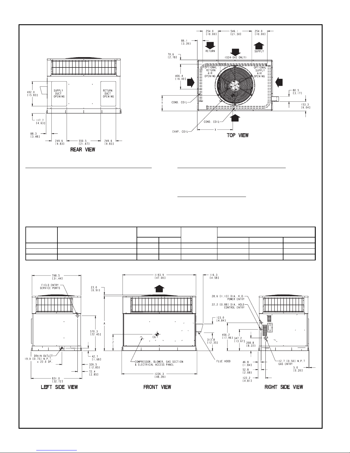
BASE UNIT DIMENSIONS — UNIT SIZES 024-036
REQ’D CLEARANCES FOR OPERATION AND SERVICING. in. (mm)
Evaporator coil access side ....................36(914)
Power entry side (except for NEC requirements) ..........36(914)
Unit top ............................48(1219)
Side opposite ducts .......................36(914)
Duct panel ..........................12(304.8)*
*Minimum distances: If unit is placed less than 12 in. (304.8 mm) from wall system,
then the system performance may be compromised.
REQ’D CLEARANCES TO COMBUSTIBLE MAT’L. in. (mm)
Top of unit .........................14(355.6)
Duct side of unit .......................2(50.8)
Side opposite ducts .....................14(355.6)
Bottom of unit .......................0.50 (12.7)
Flue panel .........................36(914.4)
NEC REQ’D CLEARANCES. in. (mm)
Between units, power entry side ..............42(1066.8)
Unit and ungrounded surfaces, power entry side .........36(914)
Unit and block or concrete walls and other grounded
surfaces, control box side .................42(1066.8)
UNIT
583A
ELECTRICAL
CHARACTERISTICS
UNIT WEIGHT
UNIT HEIGHT
in. [mm]
‘‘A’’
CENTER OF GRAVITY
in. [mm]
lb kg X Y Z
024040/060 208/230-1-60 290.0 639.3 35.02 [889.5] 22.0 [558.8] 14.5 [368.3] 16.0 [406.4]
030040/060 208/230-1-60, 208/230-3-60 313.0 690.0 39.02 [991.1] 22.0 [558.8] 15.3 [387.4] 17.6 [447.0]
036060/090 208/230-1-60, 208/230-3-60, 460-3-60 321.0 707.7 35.02 [889.5] 22.0 [558.8] 15.3 [387.4] 16.5 [419.1]
LEGEND
CG — Center of Gravity
COND — Condenser
EVAP — Evaporator
NEC — National Electrical Code
REQ’D — Required
NOTE: Dimensions are in mm [in.].
8
Page 9
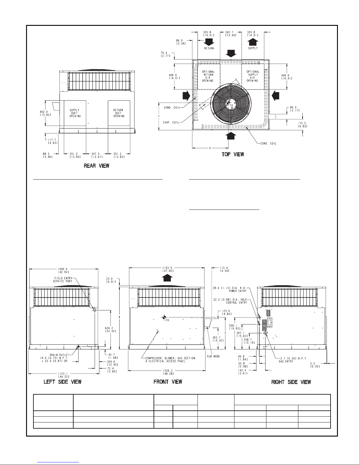
BASE UNIT DIMENSIONS — UNIT SIZES 042-060
REQ’D CLEARANCES FOR OPERATION AND SERVICING. in. (mm)
Evaporator coil access side ..................36(914)
Power entry side (except for NEC requirements) .........36(914)
Unit top ..........................48(1219)
Side opposite ducts .....................36(914)
Duct panel ........................12(304.8)*
*Minimum distances: If unit is placed less than 12 in. (304.8 mm) from wall
system, then the system performance may be compromised.
REQ’D CLEARANCES TO COMBUSTIBLE MAT’L. in. (mm)
Top of unit .........................14(355.6)
Duct side of unit .......................2(50.8)
Side opposite ducts .....................14(355.6)
Bottom of unit .......................0.50 (12.7)
Flue panel .........................36(914.4)
NEC REQ’D CLEARANCES. in. (mm)
Between units, power entry side ..............42(1066.8)
Unit and ungrounded surfaces, power entry side .........36(914)
Unit and block or concrete walls and other grounded
surfaces, control box side .................42(1066.8)
UNIT
583A
ELECTRICAL
CHARACTERISTICS
UNIT WEIGHT
UNIT HEIGHT
in. [mm]
‘‘A’’
CENTER OF GRAVITY
in. [mm]
lb kg X Y Z
042060/090 208/230-1-60, 208/230-3-60, 460-3-60 382 842.2 38.98 [ 990.2] 23.0 [584.2] 16.3 [412.8] 16.6 [421.6]
048090/115/130 208/230-1-60, 208/230-3-60, 460-3-60 421 928.2 38.98 [ 990.2] 21.5 [546.1] 16.6 [422.1] 18.0 [457.2]
060090/115/130 208/230-1-60, 208/230-3-60, 460-3-60 468 1031.7 42.98 [1091.7] 23.5 [596.9] 16.3 [412.8] 17.6 [447.0]
LEGEND
CG — Center of Gravity
COND — Condenser
EVAP — Evaporator
NEC — National Electrical Code
REQ’D — Required
NOTE: Dimensions are in mm [in.]
9
Page 10
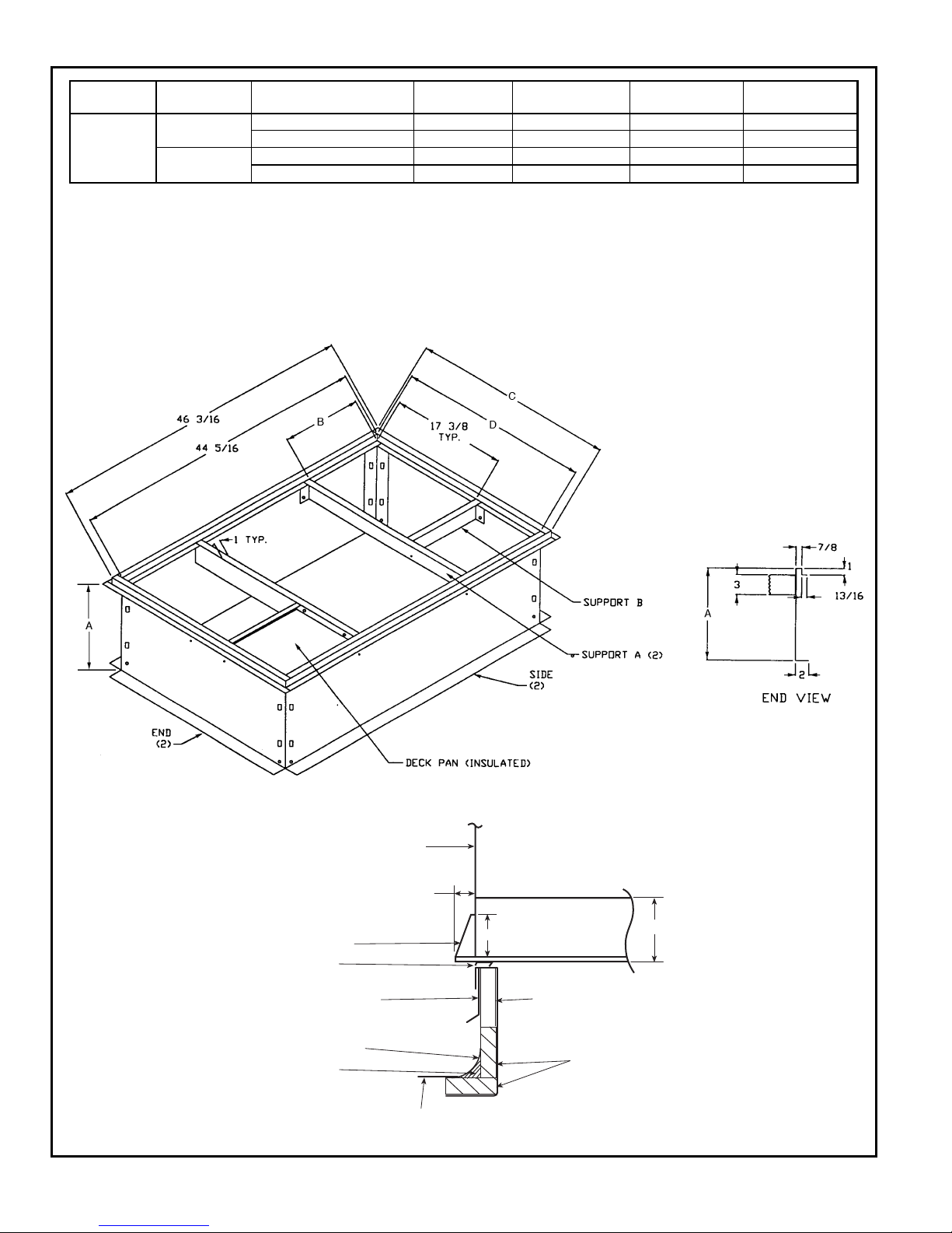
ACCESSORY DIMENSIONS
UNIT
583A
PART NUMBER
A
in. [mm]
B
in. [mm]
C
in. [mm]
D
in. [mm]
FLAT
CURB
024-036
CPRFCURB006A00 8 [203] 11
27
⁄32[301] 305⁄8[ 778] 283⁄4[ 730]
CPRFCURB007A00 14 [356] 11
27
⁄32[301] 305⁄8[ 778] 283⁄4[ 730]
042-060
CPRFCURB008A00 8 [203] 15
27
⁄32[402] 421⁄8[1070] 401⁄4[1022]
CPRFCURB009A00 14 [356] 15
27
⁄32[402] 421⁄8[1070] 401⁄4[1022]
NOTES:
1. Roof curb must be set up for unit being installed.
2. Seal strip must be applied as required to unit being installed.
3. Dimensions in [ ] are in millimeters.
4. Roof curb is made of 16 gage steel.
5. Table lists only the dimensions per part number that have changed.
6. Attach ductwork to curb (flanges of duct rest on curb).
7. Insulated panels: 1-in. thick fiberglass 1 lb density.
8. Dimensions are in inches.
3.0"
4.0"
BASE PAN
BOTTOM SUPPLY
0.75"
SIDE PANEL
SUPPORT RIB(S)
COUNTER FLASHING
(FIELD SUPPLIED)
NAILER
ROOFING FELT
(FIELD SUPPLIED)
CANT STRIP
(FIELD SUPPLIED)
ROOFING MATERIAL
(FIELD SUPPLIED)
INSULATION
(FIELD SUPPLIED)
SEAL STRIP
(FACTORY SUPPLIED)
10
Page 11

SELECTION PROCEDURE (WITH EXAMPLE)
I DETERMINE COOLING AND HEATING REQUIRE-
MENTS AT DESIGN CONDITIONS:
Given:
Required Cooling Capacity (TC) ..........35,000 Btuh
Sensible Heat Capacity (SHC) ...........25,000 Btuh
Required Heating Capacity ..............60,000 Btuh
Condenser Entering Air Temperature ............95F
Indoor-Air Temperature ...........80Fedb, 67 F ewb
Evaporator Air Quantity...................1200 Cfm
External Static Pressure ..................0.1in.wg
Electrical Characteristics ..................208-1-60
II SELECT UNIT BASED ON REQUIRED COOLING
CAPACITY.
Enter Net Cooling Capacities table at condenser entering
temperature of 95 F. Unit 583A--036 at 1200 cfm and 67 F
ewb (entering wet bulb) will provide a total capacity of
35,000 Btuh and a SHC of 25,200 Btuh. Calculate SHC
correction, if required, using Note 4 under Cooling Capacities tables.
III SELECT HEATING CAPACITY OF UNIT TO PROVIDE
DESIGN CONDITION REQUIREMENTS.
In the Heating Capacities and Efficiencies table on
page 4, note that the unit 583A--036090 will provide
71,910 Btuh with an input of 88,000 Btuh.
IV DETERMINE FAN SPEED AND POWER REQUIRE-
MENTS AT DESIGN CONDITIONS.
Before entering the air delivery tables, calculate the total
static pressure required. From the
given
example, the Wet
Coil Pressure Drop Table, and the Filter Pressure Drop
table on page 16, find at 1200 cfm:
External static pressure 0.1 in. wg
Wet Coil 0.1 in. wg
Filter 0.2 in. wg
Total static pressure 0.4 in. wg
Enter the table for Dry Coil Air Delivery — Horizontal and
Downflow Discharge on page 15. For 208 v operation, deduct 10% from value given. At 0.4 ESP (external static
pressure), the fan will deliver 1213 cfm at medium speed.
The fan speed should be set at medium speed.
V SELECT UNIT THAT CORRESPONDS TO POWER
SOURCE AVAILABLE.
The Electrical Data table on page 20 shows that the unit is
designed to operate at 208-1-60.
11
Page 12
PERFORMANCE DATA
NET COOLING CAPACITIES
583A--024
Temp (F)
Air Ent
Condenser
Evaporator Air — Cfm/BF
700/0.081 800/0.106 900/0.135
Evaporator Air — Ewb (F)
62 67 72 62 67 72 62 67 72
85
TC 22.3 24.9 27.6 22.9 25.3 28.1 23.3 25.6 28.3
SHC 20.2 16.9 13.6 21.7 18.0 14.2 23.0 19.0 14.7
kW 1.89 1.91 1.93 1.96 1.99 2.01 2.01 2.09 2.11
95
TC 21.4 23.8 26.5 21.9 24.0 27.0 22.4 24.5 27.2
SHC 19.8 16.5 13.2 21.3 17.4 13.8 22.4 18.6 14.3
kW 2.09 2.12 2.14 2.15 2.25 2.22 2.21 2.30 2.32
105
TC 20.5 22.8 25.4 21.0 23.2 25.8 21.5 23.3 26.0
SHC 19.3 16.1 12.8 20.7 17.2 13.4 21.5 18.1 13.9
kW 2.30 2.34 2.36 2.35 2.42 2.45 2.42 2.52 2.54
115
TC 19.5 21.7 24.2 20.0 22.0 24.5 20.6 22.1 24.6
SHC 18.8 15.7 12.4 20.0 16.7 13.0 20.6 17.7 13.4
kW 2.53 2.58 2.60 2.58 2.66 2.69 2.66 2.75 2.79
125
TC 18.5 20.6 23.0 19.2 20.8 23.2 19.7 20.9 23.3
SHC 18.3 15.2 11.9 19.2 16.3 12.5 19.7 17.2 13.0
kW 2.78 2.84 2.88 2.84 2.93 2.96 2.93 3.02 3.06
583A--030
Temp (F)
Air Ent
Condenser
Evaporator Air — Cfm/BF
875/0.138 1000/0.149 1125/0.159
Evaporator Air — Ewb (F)
62 67 72 62 67 72 62 67 72
85
TC 27.5 30.2 32.7 28.2 30.9 33.4 28.8 31.4 33.8
SHC 24.4 20.3 16.0 26.2 21.5 16.7 27.8 22.7 17.4
kW 2.58 2.60 2.62 2.59 2.61 2.62 2.59 2.61 2.63
95
TC 26.2 29.1 31.8 27.0 30.0 32.4 27.6 30.3 32.9
SHC 23.9 20.0 15.7 25.8 21.3 16.5 27.6 22.6 17.2
kW 2.87 2.88 2.89 2.87 2.88 2.90 2.87 2.88 2.90
105
TC 24.9 27.8 30.6 25.6 28.4 31.2 26.4 29.0 31.7
SHC 23.1 19.5 15.4 25.1 21.0 16.2 26.4 22.3 17.0
kW 3.15 3.18 3.20 3.17 3.19 3.20 3.18 3.19 3.20
115
TC 23.3 26.2 29.2 24.1 26.9 29.8 25.0 27.4 30.3
SHC 22.3 18.9 14.9 24.1 20.4 15.8 25.0 21.8 16.6
kW 3.45 3.52 3.52 3.46 3.52 3.53 3.49 3.52 3.53
125
TC 21.6 24.5 27.6 22.6 25.1 28.2 23.6 25.6 28.6
SHC 21.6 18.1 14.4 22.6 19.6 15.3 23.6 21.1 16.1
kW 3.67 3.85 3.88 3.80 3.86 3.89 3.83 3.87 3.89
See Legend and Notes on page 13.
12
Page 13
PERFORMANCE DATA (cont)
NET COOLING CAPACITIES (cont)
583A--036
Temp (F)
Air Ent
Condenser
Evaporator Air — Cfm/BF
1050/0.111 1200/0.142 1350/0.181
Evaporator Air — Ewb (F)
62 67 72 62 67 72 62 67 72
85
TC 31.4 36.2 40.6 32.4 37.1 41.2 33.1 37.6 41.5
SHC 28.7 24.4 19.7 30.9 26.0 20.4 33.1 27.3 20.9
kW 2.82 2.88 2.93 2.93 3.01 3.06 3.03 3.16 3.20
95
TC 30.0 34.3 39.0 30.7 35.0 39.6 31.7 35.7 39.9
SHC 28.0 23.7 19.2 30.1 25.2 19.9 31.7 26.7 20.5
kW 3.12 3.21 3.26 3.22 3.37 3.38 3.34 3.48 3.53
105
TC 28.6 32.6 37.3 29.4 33.4 37.9 30.4 34.0 38.2
SHC 27.3 23.1 18.6 29.4 24.7 19.4 30.4 26.1 20.0
kW 3.45 3.56 3.60 3.53 3.68 3.73 3.67 3.83 3.88
115
TC 27.0 30.8 35.7 28.2 31.5 36.2 29.1 32.0 36.4
SHC 26.4 22.4 18.0 28.2 23.9 18.8 29.1 25.4 19.4
kW 3.77 3.93 3.97 3.87 4.06 4.11 4.03 4.20 4.26
125
TC 25.5 29.0 33.9 26.7 29.4 34.4 27.8 29.8 34.6
SHC 25.5 21.7 17.4 26.7 23.2 18.2 27.8 24.6 18.8
kW 4.09 4.29 4.37 4.22 4.44 4.50 4.40 4.58 4.65
583A--042
Temp (F)
Air Ent
Condenser
Evaporator Air — Cfm/BF
1225/0.057 1400/0.075 1575/0.099
Evaporator Air — Ewb (F)
62 67 72 62 67 72 62 67 72
85
TC 39.2 42.9 46.1 39.8 43.3 46.3 40.2 43.3 46.2
SHC 35.4 29.5 23.4 37.4 30.7 23.8 39.1 31.6 24.0
kW 3.81 3.82 3.79 3.93 3.97 3.93 4.06 4.15 4.09
95
TC 37.6 41.6 44.9 38.3 42.0 45.1 38.7 42.0 45.1
SHC 34.4 29.0 23.0 36.6 30.3 23.5 38.7 31.3 23.8
kW 3.80 3.82 3.80 3.91 4.04 3.94 4.03 4.16 4.11
105
TC 35.9 40.0 43.6 36.6 40.3 43.7 37.3 40.3 43.6
SHC 33.6 28.4 22.5 35.6 29.7 23.0 37.3 30.8 23.4
kW 3.79 3.83 3.80 3.89 3.98 3.95 3.99 4.17 4.12
115
TC 34.2 38.2 42.0 34.9 38.5 42.1 35.8 38.5 42.0
SHC 32.7 27.7 21.9 34.9 29.1 22.5 35.8 30.2 22.9
kW 3.77 3.83 3.81 3.86 3.99 3.95 3.93 4.18 4.13
125
TC 32.5 36.4 40.1 33.5 36.6 40.2 34.3 36.6 40.1
SHC 31.8 26.9 21.2 33.5 28.3 21.8 34.3 29.4 22.2
kW 3.75 3.83 3.81 3.82 3.99 3.95 3.91 4.18 4.13
LEGEND
BF — Bypass Factor
Ewb — Entering Wet-Bulb
kW — Total Unit Power Input
SHC — Sensible Heat Capacity (1000 Btuh)
TC — Total Capacity (1000 Btuh) (net)
NOTES:
1. Ratings are net; they account for the effects of the evaporator-fan motor power and heat.
2. Direct interpolation is permissible. Do not extrapolate.
3. The following formulas may be used:
sensible capacity (Btuh)
t=t −
ldb edb
1.10 x cfm
t = Wet-bulb temperature corresponding to enthalpy of air leaving
lwb
evaporator coil (h )
lwb
total capacity (Btuh)
h=h −
lwb ewb
4.5 x cfm
Where: h = Enthalpy of air entering evaporator coil
ewb
4. The SHC is based on 80 F edb temperature of air entering evaporator coil.
Below 80 F edb, subtract (corr factor x cfm) from SHC.
Above 80 F edb, add (corr factor x cfm) to SHC.
Correction Factor = 1.10 x (1 − BF) x (edb − 80).
13
Page 14
PERFORMANCE DATA (cont)
NET COOLING CAPACITIES (cont)
583A--048
Temp (F)
Air Ent
Condenser
Evaporator Air — Cfm/BF
1400/0.050 1600/0.085 1800/0.119
Evaporator Air — Ewb (F)
62 67 72 62 67 72 62 67 72
85
TC 45.2 49.7 54.7 46.4 50.9 56.0 47.5 51.9 57.1
SHC 41.4 34.6 27.6 44.6 37.2 29.2 47.5 39.6 30.8
kW 4.04 4.08 4.12 4.05 4.09 4.13 4.06 4.10 4.14
95
TC 43.5 47.8 52.5 44.6 48.0 53.7 45.7 49.8 54.6
SHC 40.4 33.7 26.7 43.4 34.9 28.3 45.7 38.6 29.8
kW 4.45 4.50 4.55 4.46 4.62 4.56 4.47 4.53 4.58
105
TC 41.3 45.4 49.8 42.3 46.4 50.9 43.4 47.2 51.7
SHC 39.0 32.5 25.6 41.6 34.9 27.1 43.4 37.2 28.6
kW 4.91 4.95 5.00 4.93 4.97 5.02 4.93 4.98 5.03
115
TC 37.6 42.4 46.4 39.0 43.3 47.5 40.6 44.0 48.3
SHC 35.4 30.9 24.1 38.3 32.9 25.6 40.6 35.0 27.0
kW 5.39 5.46 5.51 5.41 5.48 5.43 5.44 5.49 5.55
125
TC 33.9 36.1 42.5 35.8 37.8 43.4 37.4 38.8 44.1
SHC 27.8 25.5 22.1 33.7 28.0 23.4 37.4 30.1 24.6
kW 6.30 5.94 6.05 6.18 5.97 6.06 6.15 5.98 6.08
583A--060
Temp (F)
Air Ent
Condenser
Evaporator Air — Cfm/BF
1750/0.082 2000/0.130 2250/0.162
Evaporator Air — Ewb (F)
62 67 72 62 67 72 62 67 72
85
TC 55.2 60.9 66.4 56.1 61.5 66.4 56.6 61.6 66.9
SHC 49.9 42.1 33.8 53.2 44.3 33.9 55.9 46.3 35.3
kW 4.92 4.97 5.00 5.14 5.23 5.28 5.41 5.55 5.59
95
TC 52.2 58.0 63.7 53.2 58.5 64.1 53.9 58.4 64.0
SHC 48.2 41.0 32.7 51.8 43.2 33.6 53.9 44.8 34.2
kW 5.39 5.57 5.50 5.64 5.75 5.77 5.90 6.03 6.09
105
TC 49.1 54.4 60.4 49.9 54.9 60.7 50.9 55.0 60.5
SHC 47.3 39.4 31.5 49.9 41.6 32.4 50.9 43.5 33.0
kW 5.87 5.98 6.02 6.13 6.22 6.30 6.34 6.57 6.62
115
TC 45.9 50.2 55.2 46.8 50.3 55.5 47.3 50.2 55.3
SHC 45.3 37.4 29.4 46.8 39.4 29.8 47.3 41.0 30.8
kW 6.39 6.48 6.54 6.57 6.75 6.81 6.85 7.07 7.14
125
TC 42.5 46.5 50.6 43.7 46.9 50.6 44.9 46.2 50.2
SHC 42.5 36.1 27.3 43.7 38.4 28.2 44.9 39.5 28.6
kW 7.03 7.13 7.13 7.22 7.38 7.40 7.51 7.67 7.72
LEGEND
BF — Bypass Factor
Ewb — Entering Wet-Bulb
kW — Total Unit Power Input
SHC — Sensible Heat Capacity (1000 Btuh)
TC — Total Capacity (1000 Btuh) (net)
NOTES:
1. Ratings are net; they account for the effects of the evaporator-fan motor power and heat.
2. Direct interpolation is permissible. Do not extrapolate.
3. The following formulas may be used:
sensible capacity (Btuh)
t=t −
ldb edb
1.10 x cfm
t = Wet-bulb temperature corresponding to enthalpy of air leaving
lwb
evaporator coil (h )
lwb
total capacity (Btuh)
h=h −
lwb ewb
4.5 x cfm
Where: h = Enthalpy of air entering evaporator coil
ewb
4. The SHC is based on 80 F edb temperature of air entering evaporator coil.
Below 80 F edb, subtract (corr factor x cfm) from SHC.
Above 80 F edb, add (corr factor x cfm) to SHC.
Correction Factor = 1.10 x (1 − BF) x (edb − 80).
14
Page 15
PERFORMANCE DATA (cont)
DRY COIL AIR DELIVERY* — HORIZONTAL AND DOWNFLOW DISCHARGE — UNIT SIZES 024-060
(Deduct 10% for 208 Volts)
230 AND 460 VOLT
Unit
583A
Motor Speed
External Static Pressure (in. wg)
0.0 0.1 0.2 0.3 0.4 0.5 0.6 0.7 0.8 0.9 1.0
024
Low
Watts 281282281278276——————
Cfm 899828757691619——————
Med
Watts — — — 375 370 363 357 352 — — —
Cfm — — — 969 897 824 744 649 — — —
High
Watts —————468457444431423—
Cfm —————994913826730620—
030
Low
Watts 246244243241———————
Cfm 982860808736———————
Med
Watts 343339336332328322317————
Cfm 1233 1170 1109 1038 953 855 754 ————
High
Watts ————441432421410400——
Cfm ————1202 1111 1021 929 826 — —
036
Low
Watts — 470 458 445 430 415 399 384 — — —
Cfm — 1463 1406 1344 1273 1188 1091 983 — — —
Med
Watts — — 514 501 487 471 455 438 422 — —
Cfm — — 1497 1428 1348 1255 1152 1042 929 — —
High
Watt — — — 646 636 626 614 602 589 — —
Cfm — — — 1491 1412 1325 1128 1120 1003 — —
042
Low
Watts 643 625 614 605 593 574 549 518 485 454 —
Cfm 1626 1614 1579 1532 1478 1421 1361 1295 1218 1120 —
Med
Watts ————726695661625591561540
Cfm ————1731 1672 1610 1541 1456 1345 1193
High
Watts ———————790766742713
Cfm ———————1699 1602 1494 1367
048
Low
Watts 614 588 577 572 566 556 539 517 491 — —
Cfm 1591 1549 1581 1490 1460 1421 1372 1312 1242 — —
Med
Watts 778 756 738 719 699 676 650 623 596 572 555
Cfm 1854 1837 1804 1759 1705 1643 1577 1508 1440 1375 1315
High
Watts ————896862829800775752728
Cfm ————1956 1879 1797 1709 1615 1514 1406
060
Low
Watts 903 898 873 842 814 792 777 764 743 701 618
Cfm 2249 2220 2149 2066 1988 1923 1871 1821 1751 1632 1424
Med
Watts — 1002 978 960 941 914 880 839 798 764 750
Cfm — 2465 2366 2272 2181 2091 2001 1909 1815 1718 1617
High
Watts — — — 1080 1080 1066 1041 1008 972 938 —
Cfm — — — 2390 2266 2208 2144 2041 1903 1772 —
*Air delivery values are without air filter and are for dry coil. (See Wet Coil Pressure Drop table.)
NOTE: Deduct field-supplied air filter pressure drop and wet coil pressure drop to obtain external static
pressure available for ducting.
15
Page 16
PERFORMANCE DATA (cont)
583A WET COIL PRESSURE DROP
UNIT SIZE
583A
AIRFLOW
(cfm)
PRESSURE DROP
(in. wg)
024
700 0.0535
800 0.067
900 0.123
030
900 0.0687
1000 0.083
1100 0.150
036
1100 0.084
1200 0.100
1300 0.177
042
1300 0.099
1400 0.177
1500 0.204
048
1500 0.199
1600 0.137
1700 0.156
060
1900 0.108
2000 0.120
2100 0.132
ECONOMIZER/1-in. FILTER PRESSURE DROP (in. wg)
UNIT 583A PRESSURE DROP
024-036 0.20
042-060 0.25
OUTDOOR SOUND: ONE-THIRD OCTAVE BAND DATA — DECIBELS
UNIT 583A
Frequency (Hz) 024 030 036 042 048 060
63 43.6 52.6 49.5 56.8 54.7 55.5
125 54.1 47.3 56.4 56.9 64.0 64.1
250 57.1 58.2 61.0 64.0 69.9 66.6
500 64.9 63.2 67.4 68.0 73.3 70.6
1000 67.6 66.1 68.1 67.7 73.5 72.6
2000 64.1 64.0 65.8 64.6 70.4 69.8
4000 59.7 61.3 64.8 61.3 66.7 67.5
8000 53.5 57.0 56.8 55.5 60.5 61.6
Bels — Sound Levels (1 bel = 10 decibels)
16
Page 17
PERFORMANCE DATA (cont)
HIGH ALTITUDE COMPENSATION
NATURAL GAS ONLY
ORIFICE CONVERSION — 3.5 in. wg MANIFOLD PRESSURE*
ALTITUDE (ft)
INPUT
(Btuh)
OUTPUT
(Btuh)
ORIFICE
NUMBER†
0-2000
40,000 32,040 #44
60,000 47,040 #38
90,000 71,910 #38
115,000 93,265 #33
130,000 104,390 #31
2001-4500
33,290 27,130 #49
49,930 40,690 #43
74,900 61,040 #43
95,700 78,000 #38
108,180 88,170 #36
4501-6000
31,310 25,520 #50
46,970 38,280 #44
70,450 57,420 #44
90,020 73,370 #40
101,760 82,930 #37
*As the height above sea level increases, there is less oxygen per cubic ft of air.
Therefore heat input rate should be reduced at higher altitudes.
†Orifices available through your distributor.
LIQUID PROPANE ONLY
ORIFICE CONVERSION — 3.5 in. wg MANIFOLD PRESSURE*
ALTITUDE (ft)
INPUT
(Btuh)
OUTPUT
(Btuh)
ORIFICE
NUMBER†
0-2000
40,000 33,200 #50
57,000 47,310 #46
85,500 70,965 #46
115,000 95,450 #42
127,000 105,410 #41
2001-4500
33,290 27,630 #53
47,430 39,370 #50
71,150 59,050 #50
95,700 79,430 #45
105,690 87,720 #44
4501-6000
31,310 25,990
NOT TO BE USED
ABOVE 4500 FT
44,620 37,030 #51
66,930 55,550 #51
90,020 74,720 #47
99,140 82,510 #45
*As the height above sea level increases, there is less oxygen per cubic ft of air.
Therefore, heat input rate should be reduced at higher altitudes.
†Orifices available through your distributor.
17
Page 18
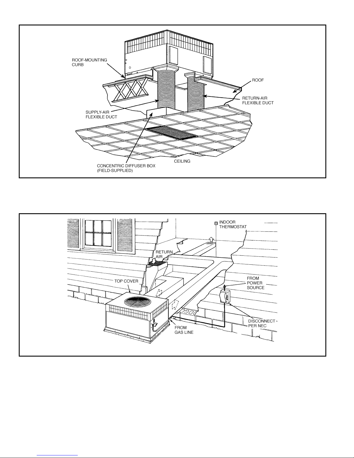
TYPICAL PIPING AND WIRING
Vertical Discharge
Horizontal Discharge
NEC — National Electrical Code
18
Page 19

APPLICATION DATA
1. Condensate trap — A 2-in. condensate trap must be field
supplied.
2. Ductwork — Secure downflow discharge ductwork to roof
curb. For horizontal discharge applications, attach ductwork
to unit with flanges.
3. To convert a unit to downflow discharge — Units are
equipped with factory-installed inserts in the downflow
openings. Remove the inserts similar to removing an electrical knock-out. Use an accessory duct cover to seal the horizontal discharge openings in the unit. Units installed in
horizontal discharge orientation do not require duct covers.
4. Airflow — Units are draw-thru in the Cooling mode and
blow-thru in the Heating mode.
5. Maximum cooling airflow — To minimize the possibility of
condensate blow-off from the evaporator, airflow through the
units should not exceed 450 cfm/ton.
6. Minimum cooling airflow — The minimum cooling airflow is
350 cfm/ton.
7. Minimum ambient operating temperature — All standard
units have a minimum ambient operating temperature of
40 F. With accessory low ambient temperature kit, units can
operate at temperatures down to 0° F.
19
Page 20
ELECTRICAL DATA
UNIT
SIZE
583A
V-PH-Hz
VOLTAGE
RANGE
COMPRESSOR
OUTDOOR FAN
MOTOR
INDOOR FAN
MOTOR
POWER SUPPLY FUSE OR
HACR BRKR
Min Max RLA LRA FLA FLA MCA MOCP*
024 208/230-1-60 187 253 10.3 56.0 0.8 2.0 15.7 25
030
208/230-1-60 187 253 13.5 73.0 0.8 2.1 19.8 30
208/230-3-60 187 253 9.0 63.0 0.8 2.1 14.2 20
036
208/230-1-60 187 253 16.7 97.0 0.8 3.6 25.3 40
208/230-3-60 187 253 11.2 75.0 0.8 3.6 18.4 25
460-3-60 414 506 5.4 37.5 0.9 1.9 9.6 15
042
208/230-1-60 187 253 17.9 104.0 1.6 4.1 28.1 45
208/230-3-60 187 253 12.4 88.0 1.6 4.1 21.2 30
460-3-60 414 506 6.1 44.0 0.9 2.0 10.5 15
048
208/230-1-60 187 253 19.5 104.0 1.6 4.1 30.1 45
208/230-3-60 187 253 12.4 88.0 1.6 4.1 21.2 30
460-3-60 414 506 5.8 44.0 0.9 2.0 10.2 15
060
208/230-1-60 187 253 28.8 169.0 1.6 6.2 43.8 60
208/230-3-60 187 253 17.3 123.0 1.6 6.2 29.4 45
460-3-60 414 506 9.0 62.0 0.9 3.2 15.4 20
LEGEND
FLA — Full Load Amps
HACR — Heating, Air Conditioning
and Refrigeration
LRA — Locked Rotor Amps
MCA — Minimum Circuit Amps
MOCP — Maximum Overcurrent Protection
RLA — Rated Load Amps
*Fuse or HACR Breaker.
NOTES:
1. In compliance with NEC (National Electrical Code) requirements for
multimotor and combination load equipment (refer to NEC
Articles 430 and 440), the overcurrent protective device for the unit
shall be fuse or HACR breaker. The CGA (Canadian Gas
Association) units may be fuse or circuit breaker.
2. Minimum wire size is based on 60 C copper wire. If other than
60 C wire is used, or if length exceeds wire length in table,
determine size from NEC.
3. Unbalanced 3-Phase Supply Voltage
Never operate a motor where a phase imbalance in supply voltage is
greater than 2%.
Use the following formula to determine the percent-
age of voltage imbalance.
% Voltage imbalance
max voltage deviation from average voltage
= 100 x
average voltage
EXAMPLE: Supply voltage is 460-3-60.
AB = 452 v
BC = 464 v
AC = 455 v
452 1 464 1 455
Average Voltage =
3
1371
=
3
= 457
Determine maximum deviation from average voltage.
(AB) 457 − 452=5v
(BC) 464 − 457=7v
(AC) 457 − 455=2v
Maximum deviation is 7 v.
Determine percent of voltage imbalance.
7
% Voltage Imbalance = 100 x
457
= 1.53%
This amount of phase imbalance is satisfactory as it is below the
maximum allowable 2%.
IMPORTANT: If the supply voltage phase imbalance is more than 2%,
contact your local electric utility company immediately.
20
Page 21
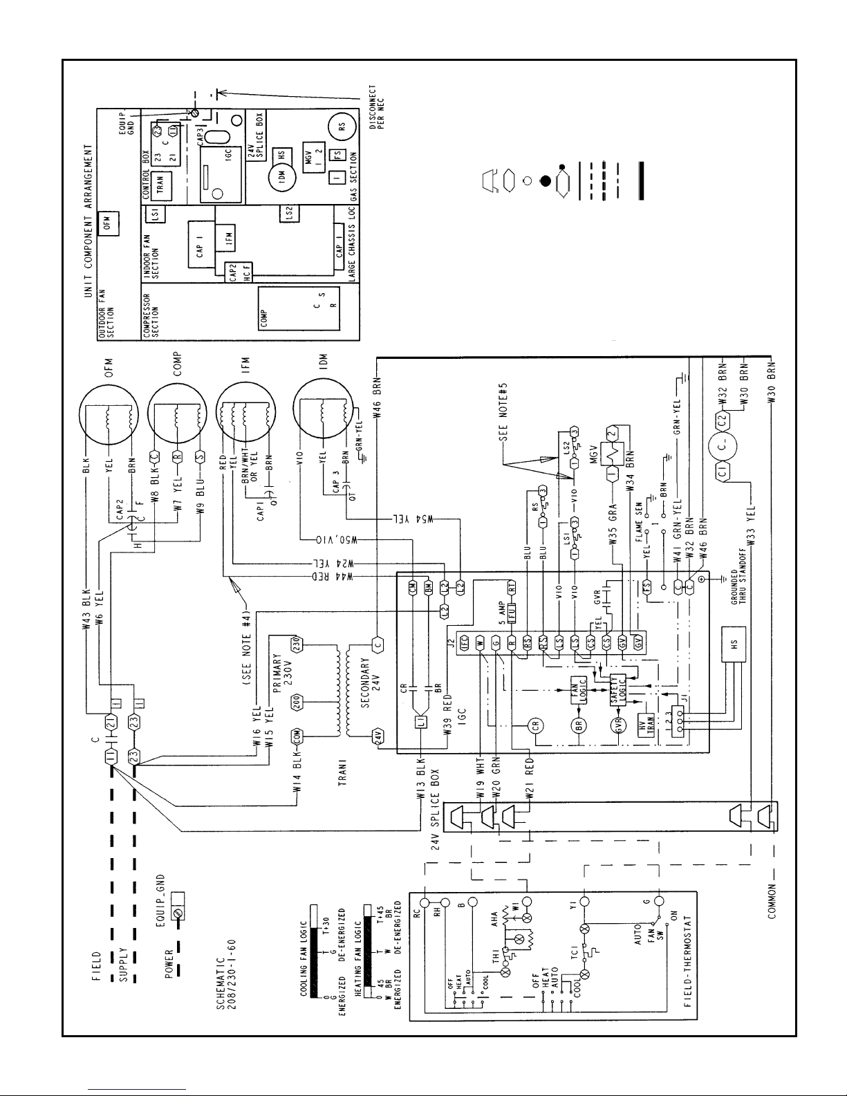
TYPICAL WIRING SCHEMATIC — 208/230-1-60 SHOWN
LEGEND
AHA — Adjustable Heat
Anticipator
BR — Blower Relay
C—Contactor
CAP — Capacitor
COMP — Compressor Motor
CR — Combustion Relay
EQUIP — Equipment
FS — Flame Sensor
FU — Fuse
GND — Ground
GVR — Gas Valve Relay
HS — Hall Effect Sensor
HV — High Voltage
Transformer
TRAN — Transformer
I—Ignitor
IDM — Induced-Draft Motor
IFM — Indoor-Fan Motor
IGC — Integrated Gas Unit
Controller
LS — Limit Switch
MGV — Main Gas Valve
NEC — National Electrical
Code
OFM — Outdoor-Fan Motor
QT — Quadruple Terminal
RS — Rollout Switch
TRAN — Transformer
Field Splice
Terminal (Marked)
Terminal
(Unmarked)
Splice
Splice (Marked)
Factory Wiring
Field Control Wiring
Field Power Wiring
Accessory or
Optional Wiring
To Indicate Common
Potential Only, Not
to Represent Wiring
NOTES:
1. If any of the original wires furnished are replaced, it must be replaced
with type 90 degree C wire or its equivalent.
2. See Trade Prices for thermostat and subbases.
3. Use 75 degree C copper conductors for field installation.
4. For high speed IFM, disconnect RED wire from IGC terminal BM and
connect BLK wire from IFM. For medium speed, disconnect RED
wire from IGC terminal BM and connect BLU wire from IFM.
5. Models 583A sizes 024-036 have LS1 and LS2 wired in series.
Models 583A sizes 042-060 have LS1 only.
21
Page 22
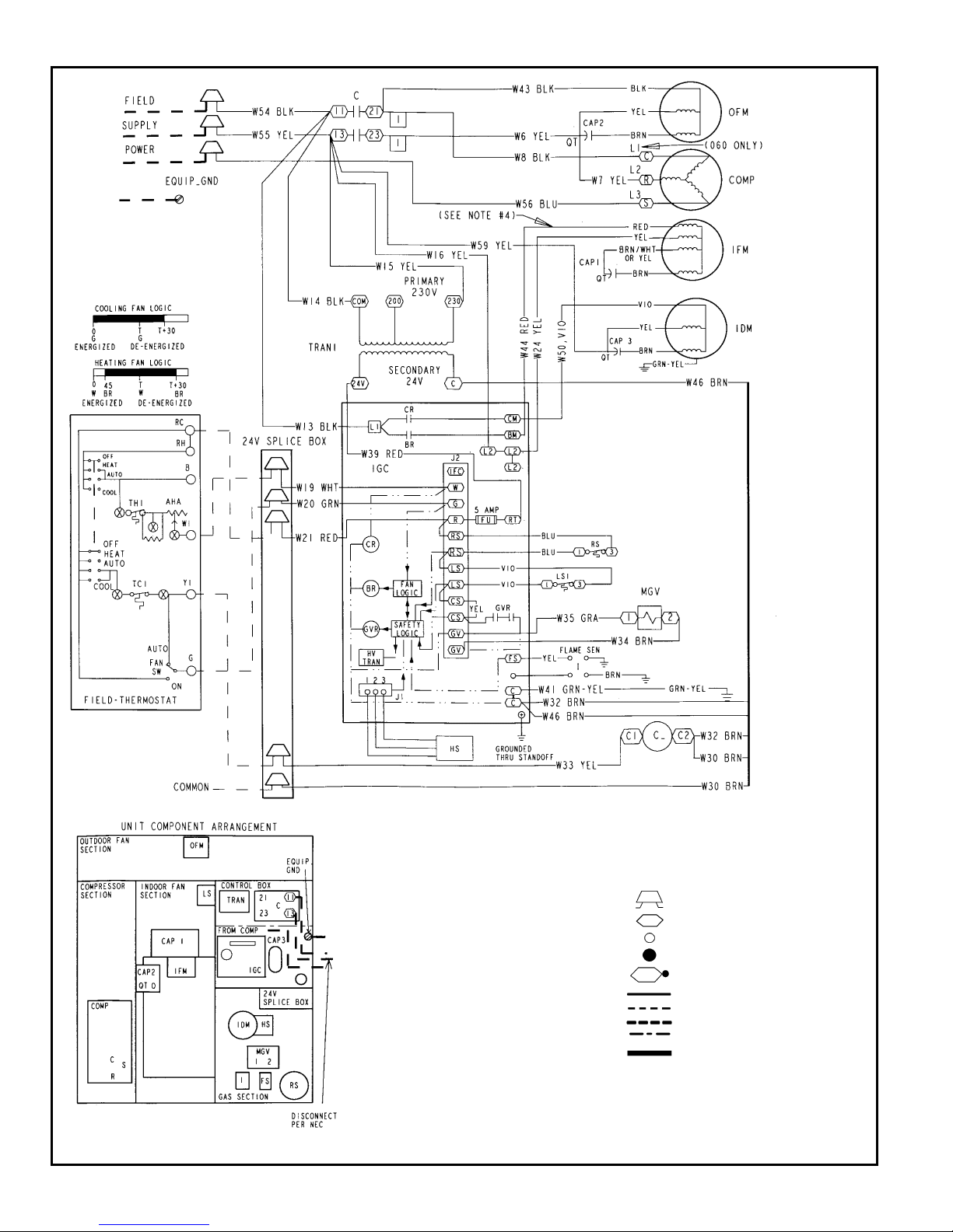
TYPICAL WIRING SCHEMATIC — 208/230-3-60 SHOWN
LEGEND
AHA — Adjustable Heat Anticipator
BR — Blower Relay
C—Contactor
CAP — Capacitor
COMP — Compressor Motor
CR — Combustion Relay
CS — Centrifugal Switch
EQUIP — Equipment
FS — Fusible Link
FU — Fuse
GND — Ground
GV — Gas Valve
GVR — Gas Valve Relay
HS — Hall Effect Sensor
HV — High Voltage
I—Ignitor
IDM — Induced-Draft Motor
IFC — Indoor-Fan Contactor
IFM — Indoor-Fan Motor
IGC — Integrated Gas Unit Controller
L1 — Line
LS — Limit Switch
LS1 — Limit Switch
MGV — Main Gas Valve
NEC — National Electrical Code
OFM — Outdoor-Fan Motor
QT — Quadruple Terminal
RS — Rollout Switch
SEN — Sensor
SW — Switch
TRAN — Transformer
Field Splice
Terminal (Marked)
Terminal (Unmarked)
Splice
Splice (Marked)
Factory Wiring
Field Control Wiring
Field Power Wiring
Accessory or Optional Wiring
To Indicate Common Potential
Only, Not to Represent Wiring
NOTES:
1. If any of the original wires furnished are replaced, they must be replaced with type 90 degree C
wire or its equivalent.
2. See Trade Prices for thermostat and subbases.
3. Use 75 degree C copper conductors for field installation.
4. For high speed IFM, disconnect RED wire from IGC terminal BM and connect BLK wire from IFM.
For medium speed, disconnect RED wire from IGC terminal BM and connect BLU wire from IFM.
22
Page 23
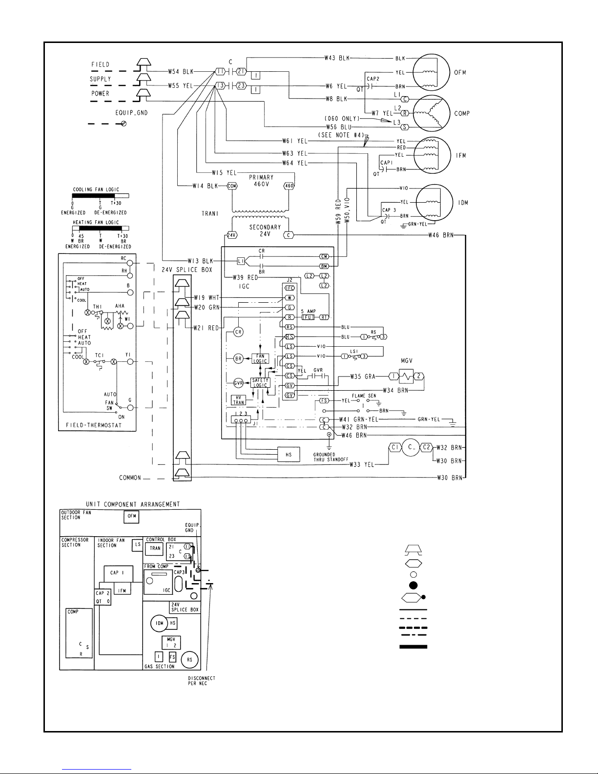
TYPICAL WIRING SCHEMATIC — 460-3-60 SHOWN
LEGEND
AHA — Adjustable Heat Anticipator
BR — Blower Relay
C—Contactor
CAP — Capacitor
COMP — Compressor Motor
CR — Combustion Relay
CS — Centrifugal Switch
EQUIP — Equipment
FS — Fusible Link
FU — Fuse
GND — Ground
GV — Gas Valve
GVR — Gas Valve Relay
HS — Hall Effect Sensor
HV — High Voltage
I—Ignitor
IDM — Induced-Draft Motor
IFC — Indoor-Fan Contactor
IFM — Indoor-Fan Motor
IGC — Integrated Gas Unit Controller
L1 — Line
LS — Limit Switch
LS1 — Limit Switch
MGV — Main Gas Valve
NEC — National Electrical Code
OFM — Outdoor-Fan Motor
QT — Quadruple Terminal
RS — Rollout Switch
SEN — Sensor
SW — Switch
TRAN — Transformer
Field Splice
Terminal (Marked)
Terminal (Unmarked)
Splice
Splice (Marked)
Factory Wiring
Field Control Wiring
Field Power Wiring
Accessory or Optional Wiring
To Indicate Common Potential
Only, Not to Represent Wiring
NOTES:
1. If any of the original wires furnished are replaced, they must be replaced with type 90 degree C wire
or its equivalent.
2. See Trade Prices for thermostat and subbases.
3. Use 75 degree C copper conductors for field installation.
4. For high speed IFM, disconnect RED wire from IGC terminal BM and connect BLK wire from IFM. For
medium speed, disconnect RED wire from IGC terminal BM and connect BLU wire from IFM.
23
Page 24

CONTROLS
OPERATING SEQUENCE
Heating — When the thermostat calls for heating, terminal ‘‘W’’
is energized, starting the induced-draft motor. When the halleffect sensor on the induced-draft motor senses that it has
reached the required speed, the burner ignition sequence begins. The indoor (evaporator) fan motor (IFM) is energized
45 seconds after flame is established. When the thermostat is
satisfied and ‘‘W’’ is deenergized, the IFM stops after a
45-second time-off delay.
Cooling — When the system thermostat calls for cooling, 24 V
is supplied to the ‘‘Y’’ and ‘‘G’’ terminals of the thermostat. This
completes the circuit to the contactor coil (C) and indoor (evaporator) fan relay (IFR). The normally open contacts of C close
and complete the circuit through compressor motor (COMP) to
outdoor (condenser) fan motor (OFM). Both motors start instantly. The set of normally open contacts of IFR close and complete the circuit through IFM. The IFM starts instantly.
On the loss of the thermostat call for cooling, 24 v is removed
from both the ‘‘Y’’ and ‘‘G’’ terminals (provided the fan switch is
in the ‘‘AUTO’’ position) deenergizing the compressor contactor
and opening the contacts supplying power to compressor/OFM.
After a 30-second delay, the IFM shuts off. If the thermostat
fan selector switch in is the ‘‘ON’’ position, the IFM will run
continuously.
NOTE: On units with a Time GuardT II device: once the com-
pressor has started and then stopped, it cannot be restarted
again until 5 minutes have elapsed.
24
Page 25

GUIDE SPECIFICATIONS
PACKAGED GAS HEATING/ELECTRIC COOLING UNITS
CONSTANT VOLUME APPLICATION
HVAC GUIDE SPECIFICATIONS
SIZE RANGE: 2 to 5 TONS, NOMINAL COOLING
40,000 TO 130,000 BTUH
NOMINAL HEATING INPUT
BRYANT MODEL NUMBER: 583A
PART 1 — GENERAL
1.01 SYSTEM DESCRIPTION
Outdoor rooftop mounted, gas heating/electric cooling unit
utilizing a hermetic compressor for cooling duty. Unit shall
discharge supply air vertically or horizontally as shown on
contract drawings. Condenser fan/coil section shall have a
draw-thru design with vertical discharge for minimum
sound levels.
1.02 QUALITY ASSURANCE
A. Unit shall be rated in accordance with ARI Standards 210/
240-94 and 270-95.
B. Unit shall be designed in accordance with UL Standard
1995.
C. Unit shall be manufactured in a facility registered to
ISO 9001 manufacturing quality standard.
D. Unit shall be UL listed and CSA certified as a total pack-
age for safety requirements.
E. Roof curb shall be designed to conform to NRCA
Standards.
F. Insulation and adhesives shall meet NFPA 90A require-
ments for flame spread and smoke generation.
G. Cabinet insulation shall meet ASHRAE Standard 62P.
1.03 DELIVERY, STORAGE AND HANDLING
Unit shall be stored and handled per manufacturer’s
recommendations.
PART 2 — PRODUCTS
2.01 EQUIPMENT
A. General:
Factory-assembled, single-piece, heating and cooling
unit. Contained within the enclosure shall be all factory
wiring, piping, controls, refrigerant charge (R-22), and
special features required prior to field start-up.
B. Unit Cabinet:
1. Unit cabinet shall be constructed of phosphated, zinccoated, pre-painted steel capable of withstanding
500 hours in salt spray.
2. Normal service shall be through a single removable
cabinet panel.
3. The unit shall be constructed on a rust proof basepan
that has an externally trapped, integrated sloped drain
pan.
4. Evaporator fan compartment top surface shall be insulated with a minimum
1
⁄2-in. thick, flexible fiberglass insulation, coated on the air side and retained by
adhesive and mechanical means. The evaporator wall
sections will be insulated with a minimum semi-rigid
foil-faced board capable of being wiped clean. Aluminum foil-faced fiberglass insulation shall be used in
the entire indoor air cavity section.
5. Unit shall have a field-supplied condensate trap.
C. Fans:
1. The evaporator fan shall be 3-speed, direct-drive, as
shown on equipment drawings.
2. Fan wheel shall be made from steel, and shall be
double-inlet type with forward curved blades with corrosion resistant finish. Fan wheel shall be dynamically
balanced.
3. Condenser fan shall be direct drive propeller type with
aluminum blades riveted to corrosion resistant steel
spiders, be dynamically balanced, and discharge air
vertically.
D. Compressor:
1. Fully hermetic compressors with factory-installed vibration isolation.
2. Scroll compressors shall be standard on all units.
E. Coils:
Evaporator and condenser coils shall have aluminum
plate fins mechanically bonded to seamless copper tubes
with all joints brazed (copper/copper and vinyl-coated
construction available as option). Tube sheet openings
shall be belled to prevent tube wear.
F. Heating Section:
1. Induced-draft combustion type with energy saving direct spark ignition system and redundant main gas
valve.
2. Induced-draft motors shall be provided with solid-state
hall-effect sensor to ensure adequate airflow for
combustion.
3. The heat exchangers shall be constructed of aluminized steel for corrosion resistance.
4. Burners shall be of the in-shot type constructed of aluminum coated steel.
5. All gas piping and electric power shall enter the unit
cabinet at a single location.
G. Refrigerant Components:
Refrigerant components shall be of the fixed orifice feed
type.
H. Filters:
Filter section shall consist of field-installed, throwaway,
1-in. thick fiberglass filters of commercially available
sizes.
I. Controls and Safeties:
1. Unit controls shall be complete with a self-contained
low voltage control circuit.
2. Compressors shall incorporate a solid-state compressor protector that provides reset capability.
J. Operating Characteristics:
1. Unit shall be capable of starting and running at 125 F
ambient outdoor temperature per maximum load criteria of ARI Standard 210.
2. Compressor with standard controls shall be capable of
operation down to 40 F ambient outdoor temperature.
3. Units shall be provided with fan time delay to prevent
cold air delivery before the heat exchanger warms up.
4. Unit shall be provided with 30-second fan time delay
after the thermostat is satisfied.
K. Electrical Requirements:
All unit power wiring shall enter the unit cabinet at a single
location.
25
Page 26

GUIDE SPECIFICATIONS (cont)
L. Motors:
1. Compressor motors shall be of the refrigerant-cooled
type with line-break thermal and current overload
protection.
2. All fan motors shall have permanently lubricated bearings, and inherent, automatic reset, thermal overload
protection.
3. Condenser-fan motor shall be totally enclosed.
M. Special Features:
1. Louvered Grille:
Wire grille shall be standard on all units. Louvered
grille shall be available as a factory-installed option to
provide hail guard and vandalism protection.
2. Coil Options:
Shall include factory-installed optional copper/copper
and vinyl-coated refrigerant coils.
3. Economizer:
a. Economizer controls capable of providing free
cooling using outside air.
b. Equipped with low leakage dampers not to
exceed 3% leakage, at 1.0 in. wg pressure
differential.
c. Spring return motor shuts off outdoor damper on
power failure.
4. Flat Roof Curb:
Curbs shall have seal strip and a wood nailer for flash-
ing and shall be installed per manufacturer’s
instructions.
5. Manual Outdoor Air Damper:
Package shall consist of damper,birdscreen, and rain-
hood which can be preset to admit outdoor air for
year-round ventilation.
6. Thermostat:
To provide for one-stage heating and cooling in addi-
tion manual or automatic changeover and indoor fan
control.
7. Natural-to-Propane Conversion Kit:
Shall be complete with all required hardware to con-
vert to liquid propane (LP) operation at 3.5 in. wg
manifold pressure.
8. Low Ambient Package:
Shall consist of a solid-state control and condenser
coil temperature sensor for controlling condenser-fan
motor operation, which shall allow unit to operate
down to 0° F outdoor ambient temperature.
9. Filter Rack Kit:
Shall provide filter mounting for downflow applications.
10. Controls Upgrade Kit:
Shall provide high and low pressure safety
protection.
11. Square-To-Round Duct Transitions:
Shall have the ability to convert the supply and return
openings from rectangular to round.
12. Compressor Protection:
Solid-state control shall protect compressor by preventing ‘‘short cycling.’’
13. Duct Conversion Kit:
Shall enable conversion of a factory supplied side
discharge unit to downflow discharge airflow unit.
14. Crankcase Heater:
Shall provide anti-floodback protection for low-load
cooling applications.
15. High Altitude Kit:
Shall consist of natural gas orifices to compensate
for gas heat operation at 2001 to 6000 ft above sea
level.
16. Low NO
x
Kit:
Shall provide NO
x
reduction to values below
40 nanograms/joule to meet California emission
requirements.
17. Compressor Hard Start Kit:
Shall provide additional starting torque for single-
phase compressors.
26
Page 27

Page 28

Copyright 1999 Bryant Heating & Cooling Systems
SPECIFICATIONS SUBJECT TO CHANGE WITHOUT NOTICE
UNIT MUST BE INSTALLED IN ACCORDANCE
WITH INSTALLATION INSTRUCTIONS
Printed in U.S.A. 4-99 5258-300
 Loading...