

Bryant 582A024040, 582A036060, 582A024060, 582A036090, 582A042060 Installation, Start-up And Service Instructions Manual
...Page 1
CONTENTS
Page
SAFETY CONSIDERATIONS ........................1
GENERAL ......................................1-3
RECEIVING AND INSTALLATION .................4-14
I. Step 1 — Check Equipment ..................4
II. Step 2 — Provide Unit Support ...............4
III. Step 3 — Field Fabricate Ductwork ............4
IV. Step 4 — Provide Clearances .................4
V. Step 5 — Rig and Place Unit .................4
VI. Step 6 — Connect Condensate Drain ..........7
VII. Step 7 — Install Flue Hood ...................7
VIII. Step 8 — Install Gas Piping ..................7
IX. Step 9 — Install Duct Connections ...........10
X. Step 10 — Install Electrical Connections ......11
PRE-START-UP ................................14,15
START-UP ....................................15-29
I. Check for Refrigerant Leaks .................15
II. Start Up Heating Section and
Make Adjustments .........................15
III. Start Up Cooling Section and
Make Adjustments .........................18
MAINTENANCE ................................29-32
I. Air Filter ..................................30
II. Evaporator Blower and Motor ................30
III. Flue Gas Passageways .....................30
IV. Combustion-Air Blower .....................30
V. Limit Switch ..............................30
VI. Burner Ignition ............................31
VII. Main Burners .............................31
VIII. Condenser Coil, Evaporator Coil, and
Condenser Drain Pan .......................31
IX. Condenser Fan ............................32
X. Electrical Controls and Wiring ...............32
XI. Refrigerant Circuit .........................32
XII. Gas Input .................................32
XIII. Evaporator Airflow .........................32
XIV. Metering Device — Acutrol™ Device ..........32
XV. Liquid Line Strainer ........................32
TROUBLESHOOTING ...........................33-35
START-UP CHECKLIST ..........................CL-1
NOTE TO INST ALLER — Before the installation, READ THESE
INSTRUCTIONS CAREFULLY AND COMPLETELY. Also,
make sure the User’s Manual and Replacement Guide are
left with the unit after installation. The furnace is NOT to be
used for temporary heating of buildings or structures under
construction.
SAFETY CONSIDERATIONS
Installation and servicing of air-conditioning equipment can
be hazardous due to system pressure and electrical components. Only trained and qualified personnel should install,
repair, or service air-conditioning equipment.
Untrained personnel can perform basic maintenance functions of cleaning coils and filters. All other operations should
be performed by trained service personnel. When working on
air-conditioning equipment, observe precautions in the literature, tags and labels attached to the unit, and other safety
precautions that may apply.
Follow all safety codes. Wear safety glasses and work gloves.
Use quenching cloth for unbrazing operations. Have fire extinguisher available for all brazing operations.
WARNING:
Improper installation, adjustment, alteration, service, maintenance, or use can cause carbon monoxide poisoning, fire, or an explosion which can result
in personal injury or unit damage. Consult a qualified
installer, service agency, or gas supplier for information or assistance. The qualified installer or agency must
use only factory-authorized kits or accessories when modifying this product.
WARNING:
Before performing service or maintenance operations on unit, turn off gas supply then unit
main power switch. Electrical shock could cause personal injury.
GENERAL
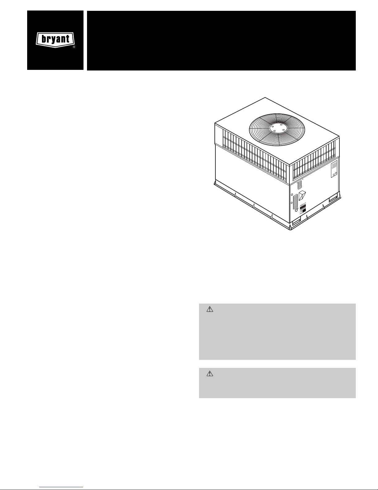
The 582A and 583A units (see Fig. 1) are fully self-contained,
combination Category I gas heating/electric cooling units designed for outdoor installation. See Fig. 2 and 3 (pages 2,3)
for unit dimensions. All unit sizes have return and discharge
openings for both horizontal and downflow configurations, and
are factory shipped with all downflow duct openings covered.
Units may be installed on a rooftop, a cement slab, or directly on the ground (if permitted by local codes). See Fig. 4
for roof curb dimensions.
Fig. 1 — Units 582A and 583A
(Shown with Accessory Wire Grille)
installation, start-up
and service instructions
SINGLE PACKAGE GAS HEATING/
ELECTRIC COOLING UNITS
582A
Sizes 018-060
583A
Sizes 024-060
1
1
⁄2to 5 Nominal Tons
Cancels: II 582A-18-1 II 582A-18-2
3/15/99
Page 2
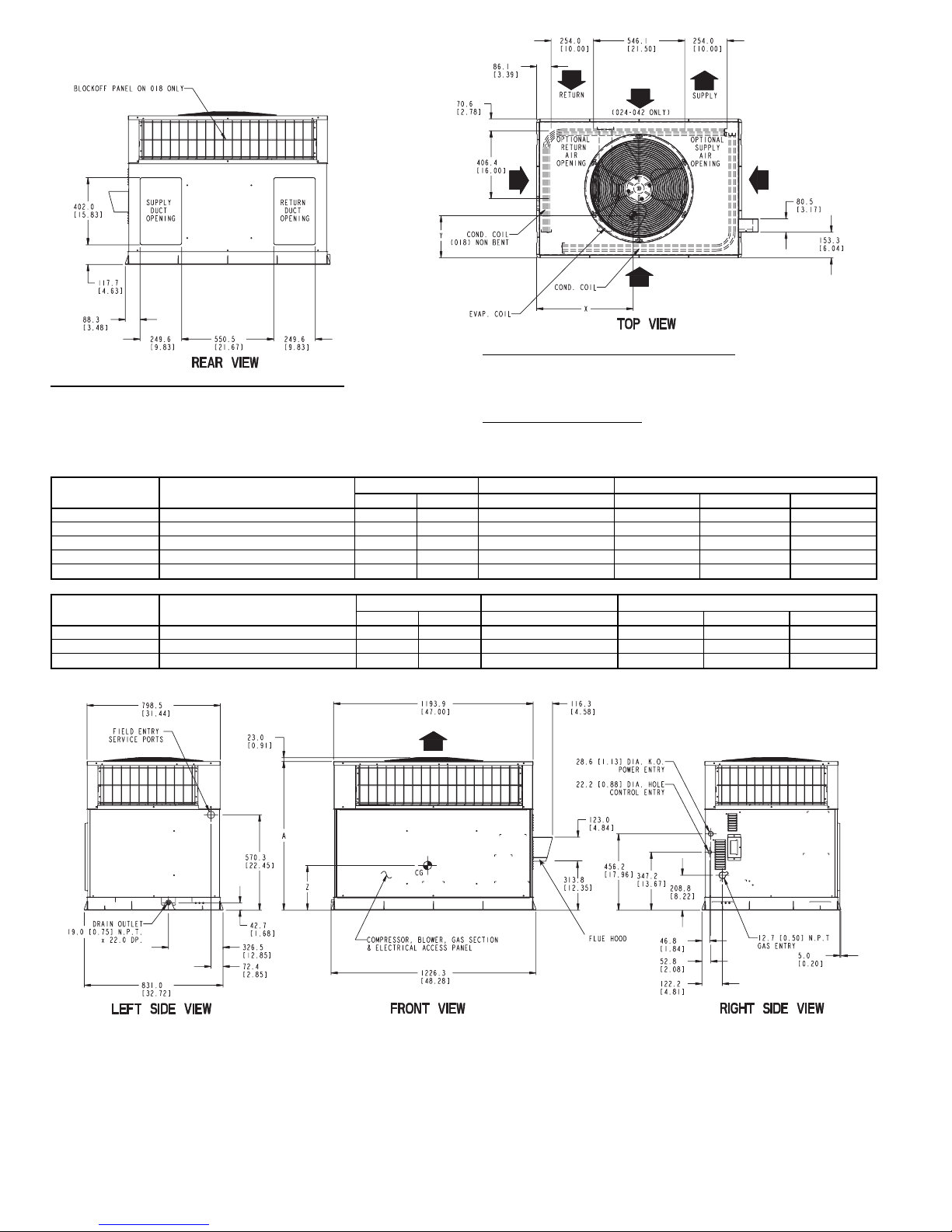
REQ’D CLEARANCES FOR OPERATIONAND SERVICING. in. (mm)
Evaporator coil access side ......................36(914)
Power entry side (except for NEC requirements) ..............36(914)
Unit top .............................48(1219)
Side opposite ducts .........................36(914)
Duct panel ...........................12(304.8)*
*Minimum distances: If unit is placed less than 12 in. (304.8 mm) from wall system, then the
system performance may be compromised.
REQ’D CLEARANCES TO COMBUSTIBLE MAT’L. in. (mm)
Top of unit ............................14(355.6)
Duct side of unit ...........................2(50.8)
Side opposite ducts ........................14(355.6)
Bottom of unit ..........................0.50 (12.7)
Flue panel ............................36(914.4)
NEC REQ’D CLEARANCES. in. (mm)
Between units, power entry side ...................42(1066.8)
Unit and ungrounded surfaces, power entry side ..............36(914)
Unit and block or concrete walls and other grounded
surfaces, control box side .....................42(1066.8)
UNIT
582A
ELECTRICAL
CHARACTERISTICS
UNIT WEIGHT UNIT HEIGHT in. [mm] CENTER OF GRAVITY in. [mm]
lb kg A X Y Z
582A018040 208/230-1-60 249.0 113.2 35.02 [889.5] 20.0 [508.0] 14.0 [355.6] 15.0 [381.0]
582A024040/060 208/230-1-60 280.0 127.3 35.02 [889.5] 22.5 [571.5] 13.0 [330.2] 15.0 [381.0]
582A030040/060 208/230-1-60, 208/230-3-60 280.0 127.3 35.02 [889.5] 21.5 [546.1] 13.75 [349.3] 15.0 [381.0]
582A036060/090 208/230-1-60, 208/230-3-60, 460-3-60 314.0 142.7 35.02 [889.5] 22.5 [571.5] 14.0 [355.6] 13.0 [330.2]
582A042060/090 208/230-1-60, 208/230-3-60, 460-3-60 355.0 161.4 35.02 [889.5] 21.5 [546.1] 13.5 [342.9] 13.0 [330.2]
UNIT
ELECTRICAL
CHARACTERISTICS
UNIT WEIGHT UNIT HEIGHT in. [mm] CENTER OF GRAVITY in. [mm]
lb kg A X Y Z
583A024040/060 208/230-1-60 290.0 639.3 35.02 [889.5] 22.0 [558.8] 14.5 [368.3] 16.0 [406.4]
583A030040/060 208/230-1-60, 208/230-3-60 313.0 690.0 39.02 [991.1] 22.0 [558.8] 15.3 [387.4] 17.6 [447.0]
583A036060/090 208/230-1-60, 208/230-3-60, 460-3-60 321.0 707.7 35.02 [889.5] 22.0 [558.8] 15.3 [387.4] 16.5 [419.1]
LEGEND
CG — Center of Gravity
COND — Condenser
EVAP — Evaporator
NEC — National Electrical Code
REQ’D — Required
NOTE: Dimensions are in mm [in.]
Fig. 2 — 582A018-042 and 583A024-036 Unit Dimensions
—2—
Page 3
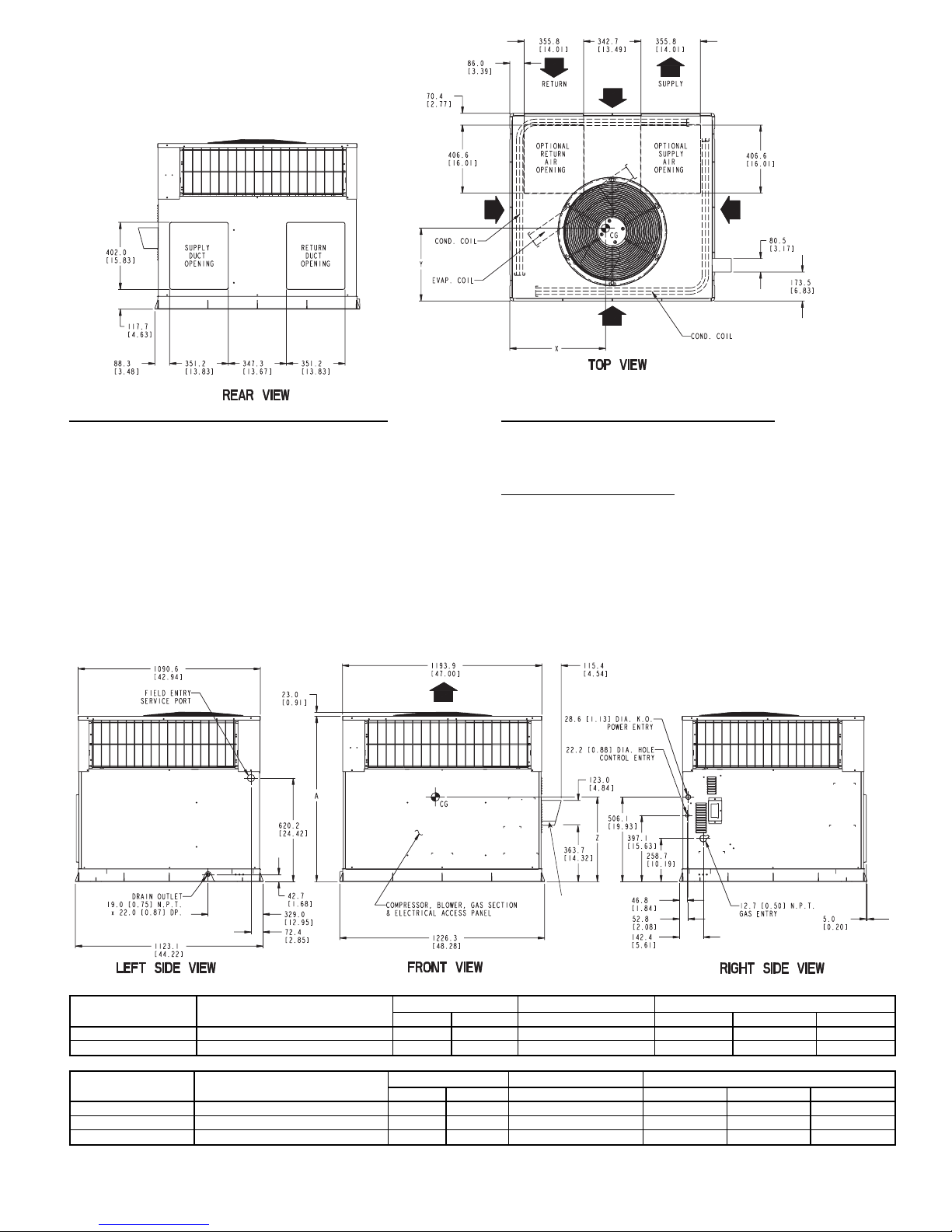
FLUE HOOD
REQ’D CLEARANCES FOR OPERATION AND SERVICING. in. (mm)
Evaporator coil access side .....................36(914)
Power entry side (except for NEC requirements) ............36(914)
Unit top ............................48(1219)
Side opposite ducts ........................36(914)
Duct panel ...........................12(304.8)*
*Minimum distances: If unit is placed less than 12 in. (304.8 mm) from wall system, then
the system performance may be compromised.
REQ’D CLEARANCES TO COMBUSTIBLE MAT’L. in. (mm)
T op of unit ...........................14(355.6)
Duct side of unit ..........................2(50.8)
Side opposite ducts .......................14(355.6)
Bottom of unit .........................0.50 (12.7)
Flue panel ...........................36(914.4)
NEC REQ’D CLEARANCES. in. (mm)
Between units, power entry side ..................42(1066.8)
Unit and ungrounded surfaces, power entry side ............36(914)
Unit and block or concrete walls and other grounded
surfaces, control box side ....................42(1066.8)
LEGEND
CG — Center of Gravity
COND — Condenser
EVAP — Evaporator
NEC — National Electrical Code
REQ’D — Required
NOTE: Dimensions are in mm [in.]
UNIT
ELECTRICAL
CHARACTERISTICS
UNIT WEIGHT UNIT HEIGHT in. [mm] CENTER OF GRAVITY in. [mm]
lb kg A X Y Z
582A048090/115/130 208-230/1/60, 208/230-3-60, 460-3-60 415 188.6 38.98 [990.2] 22 [558.5] 16 [406.4] 17 [432.0]
582A060090/115/130 208/230-1-60, 208/230-3-60, 460-3-60 450 204.5 38.98 [990.2] 22 [558.5] 16 [406.4] 17 [432.0]
UNIT
ELECTRICAL
CHARACTERISTICS
UNIT WEIGHT UNIT HEIGHT in. [mm] CENTER OF GRAVITY in. [mm]
lb kg A X Y Z
583A042060/090 208/230-1-60, 208/230-3-60, 460-3-60 382.0 842.2 38.98 [990.2] 23.0 [584.2] 16.3 [412.8] 16.6 [421.6]
583A048090/115/130 208/230-1-60, 208/230-3-60, 460-3-60 421.0 928.2 38.98 [990.2] 21.5 [546.1] 16.6 [422.1] 18.0 [457.2]
583A060090/115/130 208/230-1-60, 208/230-3-60, 460-3-60 468.0 1031.7 42.98 [1091.7] 23.5 [596.9] 16.3 [412.8] 17.6 [447.0]
Fig. 3 — 582A048,060 and 583A042,048,060 Unit Dimensions
—3—
Page 4
RECEIVING AND INSTALLATION
I. STEP 1 — CHECK EQUIPMENT
A. Identify Unit
The unit model number and serial number are stamped on
unit identification plate. Check this information against shipping papers and job data.
B. Inspect Shipment
Inspect for shipping damage while unit is still on shipping
pallet. If unit appears to be damaged or is torn loose from its
anchorage, have it examined by transportation inspectors before removal. Forward claim papers directly to transportation company. Manufacturer is not responsible for any damage incurred in transit.
Check all items against shipping list. Immediately notify the
nearest Bryant Air Conditioning office if any item is missing.
To prevent loss or damage, leave all parts in original packages until installation.
II. STEP 2 — PROVIDE UNIT SUPPORT
A. Roof Curb
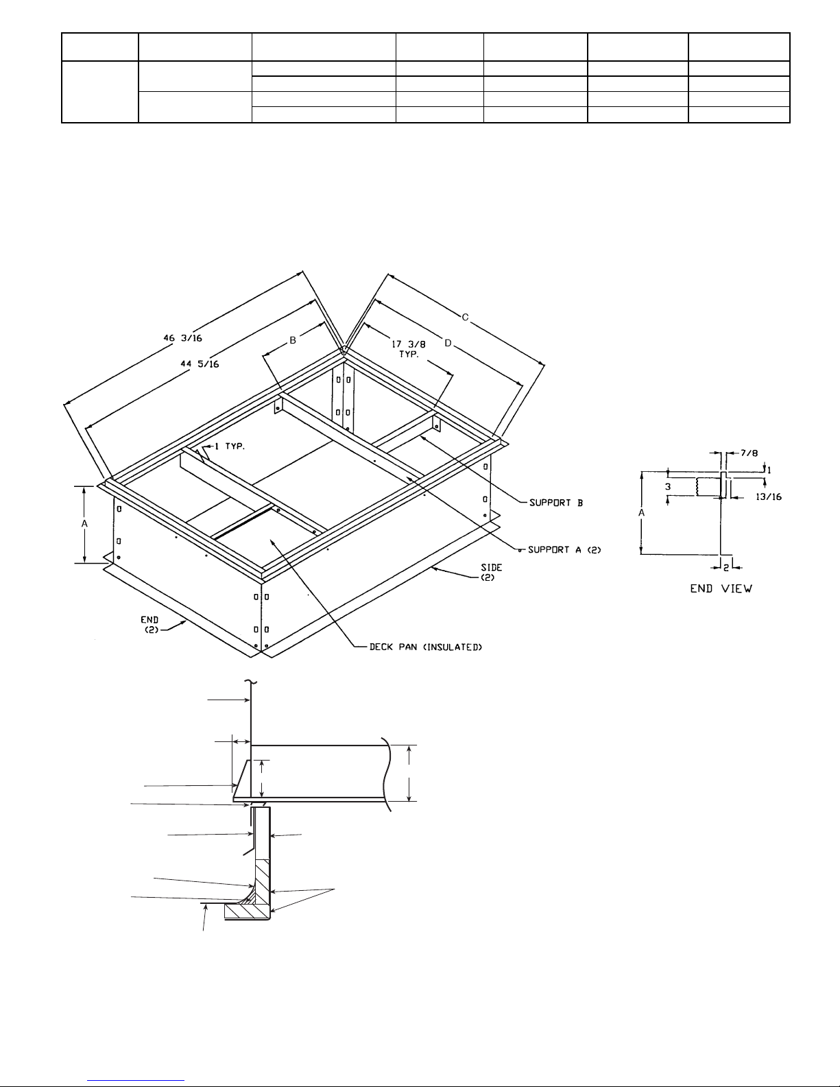
Install accessory roof curb in accordance with instructions
shipped with curb. See Fig. 4 for roof curb dimensions. Install insulation, cant strips, roofing, and flashing. Ductwork
must be attached to curb.
IMPORTANT: The gasketing of the unit to the roof curb is
critical for a watertight seal. Install gasketing material supplied with the roof curb. Improperly applied gasketing can
result in water leaks, air leaks, and poor unit performance.
Curb should be level to within
1
⁄4inch. This is necessary for
unit drain to function properly. Refer to accessory roof curb
installation instructions for additional information as
required.
B. Slab Mount
Place the unit on a solid, level concrete pad that is a minimum of 4 in. thick with 2 in. above grade. The slab should be
flush on the compressor end of the unit (to allow condensate
drain installation) and should extend 2 in. on the three remaining sides of the unit. See Fig. 5. Do not secure the unit
to the slab except when required by local codes.
C. Ground Mount
The unit may be installed either on a slab or placed directly
on the ground if local codes permit. Place the unit on level
ground prepared with gravel for condensate discharge.
III. STEP 3 — FIELD FABRICATE DUCTWORK
Secure all ducts to roof curb and building structure on vertical discharge units. Do not connect ductwork to unit. For horizontal applications, unit is provided with flanges on the horizontal openings.All ductwork should be secured to the flanges.
Insulate and weatherproof all external ductwork, joints,
and roof openings with counter flashing and mastic in
accordance with applicable codes.
Ducts passing through an unconditioned space must be insulated and covered with a vapor barrier.
If a plenum return is used on a vertical unit, the return should
be ducted through the roof deck to comply with applicable
fire codes.
Aminimum clearance is not required around ductwork. Cabinet return-air static shall not exceed −.25 in. wg.
IV. STEP 4 — PROVIDE CLEARANCES
The required minimum operating and service clearances are
shown in Fig. 2 and 3. Adequate combustion, ventilation, and
condenser air must be provided, in accordance with section
5.3, Air for Combustion and Ventilation, of the National Fuel
Gas CodeANSI (American National Standards Institute) Z223.1
(in Canada, sections 7.2, 7.3 or 7.4 or Can/CGA [Canadian
Gas Association] B149 Installation Codes), or applicable provisions of local building code.
CAUTION:
Do not restrict condenser airflow. An air
restriction at either the outdoor-air inlet or the fan discharge can be detrimental to compressor life.
The condenser fan pulls air through the condenser coil and
discharges it through the top cover. Be sure that the fan discharge does not recirculate to the condenser coil. Do not locate the unit in either a corner or under an overhead obstruction.
The minimum clearance under a partial overhang (such as a
normal house overhang) is 48-in. above the unit top. The maximum horizontal extension of a partial overhang must not exceed 48 inches.
Do not place the unit where water, ice, or snow from
an overhang or roof will damage or flood the unit. Do not install the unit on carpeting, tile, or other combustible
materials. The unit may be installed on wood flooring or on
Class A, B, or C roof covering materials.
V. STEP 5 — RIG AND PLACE UNIT
CAUTION:
When installing the unit on a rooftop, be
sure the roof will support the additional weight.
Use spreader bars or crate top when rigging the unit. The
units must be rigged for lifting as shown in Fig. 6. Refer to
Tables 1 and 2 for operating weight. Use extreme caution to
prevent damage when moving the unit. Unit must remain in
an upright position during all rigging and moving operations. The unit must be level for proper condensate drainage;
therefore, the ground-level pad or accessory roof curb must
be level before setting the unit in place. When a fieldfabricated support is used, be sure that the support is level
and properly supports the unit.
—4—
Page 5
UNIT SIZE PART NUMBER
A
in. [mm]
B
in. [mm]
C
in. [mm]
D
in. [mm]
FLAT
CURB
582A018-042
583A024-036
CPRFCURB006A00 8 [203] 11
27
⁄32[301] 305⁄8[778] 283⁄4[730]
CPRFCURB007A00 14 [356] 11
27
⁄32[301] 305⁄8[778] 283⁄4[730]
582A048, 060
583A042-060
CPRFCURB008A00 8 [203] 15
27
⁄32[402] 421⁄8[1070] 401⁄4[1022]
CPRFCURB009A00 14 [356] 15
27
⁄32[402] 421⁄8[1070] 401⁄4[1022]
NOTES:
1. Roof curb must be set up for unit being installed.
2. Seal strip must be applied as required to unit being installed.
3. Dimensions in [ ] are in millimeters.
4. Roof curb is made of 16 gage steel.
5. Table lists only the dimensions per part number that have changed.
6. Attach ductwork to curb (flanges of duct rest on curb).
7. Insulated panels: 1-in. thick fiberglass 1 lb density.
8. Dimensions are in inches.
3.0"
4.0"
BASE PAN
BOTTOM SUPPLY
0.75"
SIDE PANEL
SUPPORT RIB(S)
COUNTER FLASHING
(FIELD SUPPLIED)
NAILER
ROOFING FELT
(FIELD SUPPLIED)
CANT STRIP
(FIELD SUPPLIED)
ROOFING MATERIAL
(FIELD SUPPLIED)
INSULATION
(FIELD SUPPLIED)
SEAL STRIP
(FACTORY SUPPLIED)
FULL PERIMETER CURB
Fig. 4 — Roof Curb Dimensions
—5—
Page 6
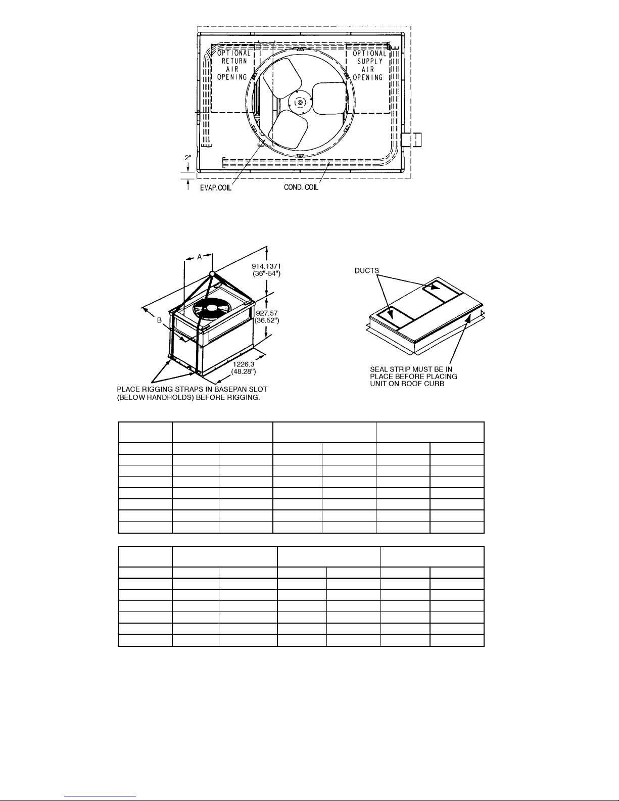
Fig. 5 — Slab Mounting Details
UNIT
582A
MAXIMUM
WEIGHT
AB
Size lb kg in. mm in. mm
018 271 123.2 20.0 508.0 14.0 355.6
024 302 137.3 22.5 571.5 13.0 330.2
030 302 137.3 21.5 546.1 13.75 349.3
036 336 152.7 22.5 571.5 14.0 355.6
042 377 171.4 21.5 546.1 13.5 342.9
048 437 198.6 22.0 558.5 17.0 432.0
060 472 214.5 22.0 558.5 17.0 432.0
UNIT
583A
MAXIMUM
WEIGHT
AB
Size lb kg in. mm in. mm
024 312 688.0 22.0 558.5 14.5 368.3
030 335 738.7 22.0 558.5 15.3 388.6
036 343 756.4 22.0 558.5 15.3 388.6
042 404 890.9 23.0 584.2 16.3 414.0
048 443 976.9 21.5 546.1 16.3 414.0
060 490 1080.5 23.5 596.9 16.3 414.3
Fig. 6 — Suggested Rigging
—6—
Page 7
VI. STEP 6 — CONNECT CONDENSATE DRAIN
NOTE: When installing condensate drain connection be sure
to comply with local codes and restrictions.
Models 582A and 583A dispose of condensate water through
a
3
⁄4in. NPT fitting which exits through the compressor ac-
cess panel. See Fig. 2 and 3 for location.
Condensate water can be drained directly onto the roof in roof-
top installations (where permitted) or onto a gravel apron in
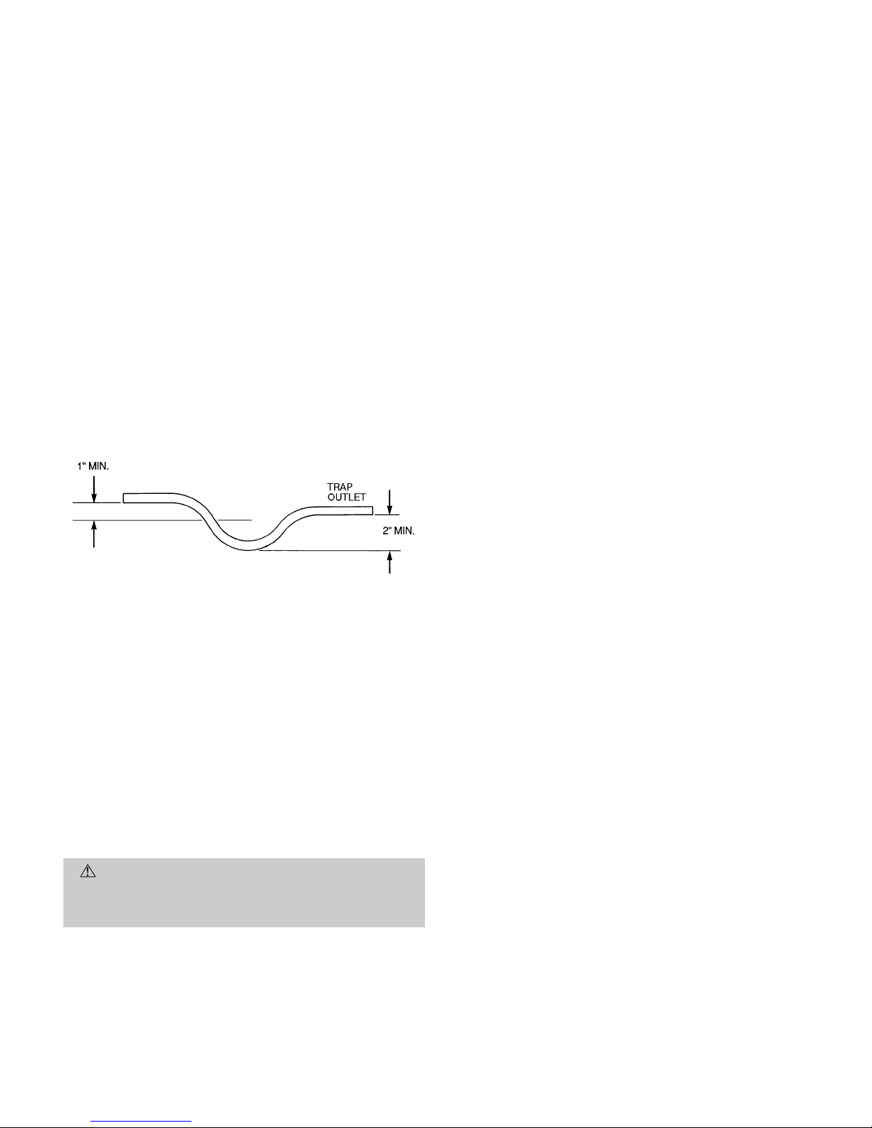
ground-level installations. Install a field-supplied condensate trap at end of condensate connection to ensure proper
drainage. Make sure that the outlet of the trap is at least
1 in. lower than the drain-pan condensate connection to prevent the pan from overflowing. See Fig. 7. Prime the trap with
water. When using a gravel apron, make sure it slopes away
from the unit.
If the installation requires draining the condensate water away
from the unit, install a 2-in. trap at the condensate connection to ensure proper drainage. See Fig. 7. Make sure that
the outlet of the trap is at least 1 in. lower than the drainpan condensate connection to prevent the pan from overflowing. Prime the trap with water. Connect a drain tube using a
minimum of
3
⁄4-in. PVC or3⁄4-in. copper pipe (all fieldsupplied) at the outlet end of the 2-in. trap. Do not undersize
the tube. Pitch the drain tube downward at a slope of at least
one in. for every 10 ft of horizontal run. Be sure to check the
drain tube for leaks.
VII. STEP 7 — INSTALL FLUE HOOD
The flue hood assembly is shipped screwed to the coil panel
in the indoor blower compartment. Remove the service access panel to locate the assembly.
For units being installed in California Air Quality Management Districts which require NO
x
emissions of 40 nanograms/
joule or less, a field-installed low NO
x
kit must be installed.
For 40,000 and 60,000 Btuh input models, use kit part number CPLOWNOX002A00. This kit contains two NO
x
reduction baffles and one conversion label. For 90,000 115,000 and
130,000 Btuh input models, use kit part number
CPLOWNOX003A00. This kit contains three NO
x
reduction
baffles and one conversion label.
CAUTION:
The venting system is designed to ensure proper venting. The flue hood assembly must be
installed as indicated in this section of the unit installation instructions.
Install the flue hood as follows:
1. This installation must conform with local building codes
and with the National Fuel Gas Code (NFGC), ANSI
Z223.1 (in Canada, CAN/CGA B149.1, and B149.2) or
NFPA (National Fire Protection Association) latest revision. Refer to Provincial and local plumbing or wastewater codes and other applicable local codes.
2. Remove flue hood from shipping location (inside the blower
compartment). Place vent cap assembly over flue panel.
Orient screw holes in vent cap with holes in the flue panel.
3. Secure flue hood to flue panel by inserting a single screw
on the right side and the left side of the hood.
VIII. STEP 8 — INSTALL GAS PIPING
The gas supply pipe enters the unit through the access hole
provided. The gas connection to the unit is made to the
1
⁄2-in.
FPT gas inlet on the manual shutoff or gas valve.
Install a gas supply line that runs to the heating section. Re-
fer to Table 3 and the NFGC for gas pipe sizing. Do not use
cast-iron pipe. It is recommended that a black iron pipe is
used. Check the local utility for recommendations concerning existing lines. Size gas supply piping for 0.5 in. wg maximum pressure drop. Never use pipe smaller than the
1
⁄2-in.
FPT gas inlet on the unit gas valve.
For natural gas applications, the gas pressure at unit gas connection must not be less than 4.0 in. wg or greater than
13 in. wg while the unit is operating. For propane applications, the gas pressure must not be less than 4.0 in. wg or
greater than 13 in. wg at the unit connection.
An
1
⁄8-in. NPT plugged tapping accessible for test gage connection must be installed immediately upstream of the gas
supply connection to the gas valve.
When installing the gas supply line, observe local codes pertaining to gas pipe installations. Refer to the NFGC ANSI
Z223.1-1988 NFPAlatestedition(in Canada, CAN/CGAB149.1,
(2)-M86). In the absence of local building codes, adhere to the
following pertinent recommendations:
1. Avoid low spots in long runs of pipe. Grade all pipe
1
⁄4inch in every 15 ft to prevent traps. Grade all horizontal runs downward to risers. Use risers to connect to
heating section and to meter.
2. Protect all segments of piping system against physical
and thermal damage. Support all piping with appropriate straps, hangers, etc. Use a minimum of one hanger
every 6 ft. For pipe sizes larger than
1
⁄2in., follow rec-
ommendations of national codes.
3. Apply joint compound (pipe dope) sparingly and only to
male threads of joint when making pipe connections. Use
only pipe dope that is resistant to action of liquefied
petroleum gases as specified by local and/or national codes.
Never use Teflon tape.
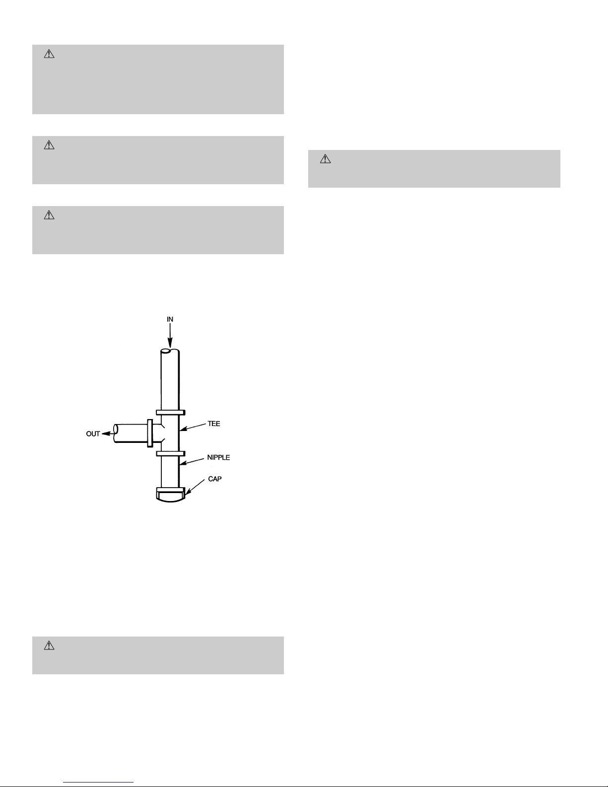
4. Install sediment trap in riser leading to heating section
per Fig. 8. This drip leg functions as a trap for dirt and
condensate.
5. Install an accessible, external, manual main shutoff valve
in gas supply pipe within 6 ft of heating section.
6. Install ground-joint union close to heating section between unit manual shutoff and external manual main
shutoff valve.
7. Pressure-test all gas piping in accordance with local and
national plumbing and gas codes before connecting piping to unit.
NOTE: Pressure test the gas supply system after the gas sup-
ply piping is connected to the gas valve. The supply piping
must be disconnected from the gas valve during the testing of the piping systems when test pressure is in excess of
0.5 psig. Pressure test the gas supply piping system at pressures equal to or less than 0.5 psig. The unit heating section
must be isolated from the gas piping system by closing the
external main manual shutoff valve and slightly opening the
ground-joint union.
Fig. 7 — Condensate Trap
—7—
Page 8
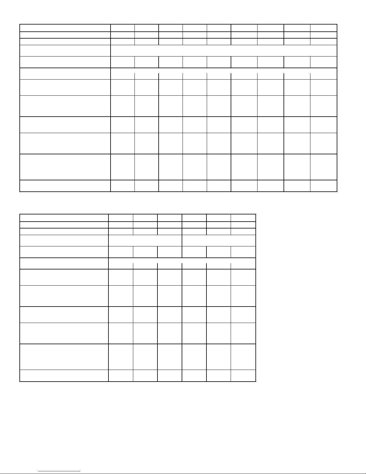
Table 1 — Physical Data — Unit 582A
UNIT SIZE 582A 018040 024040 024060 030040 030060 036060 036090 042060 042090
NOMINAL CAPACITY (ton) 1
1
⁄
2
222
1
⁄
2
2
1
⁄
2
333
1
⁄
2
3
1
⁄
2
OPERATING WEIGHT (lb) 249 280 280 280 280 314 314 355 355
COMPRESSORS Reciprocating
Quantity 1
REFRIGERANT (R-22)
Quantity (lbs) 2.6 3.5 3.5 3.65 3.65 3.75 3.75 5.7 5.7
REFRIGERANT METERING DEVICE Acutrol™ Device
Orifice ID (in.) .034 .034 .034 .034 .034 .032 .032 .034 .034
CONDENSER COIL
Rows...Fins/in. 1...17 1...17 1...17 1...17 1...17 1...17 1...17 1...17 1...17
Face Area (sq ft) 6.1 9.1 9.1 9.1 9.1 9.1 9.1 9.1 9.1
CONDENSER FAN
Nominal Cfm 2000 2400 2400 2400 2400 3000 3000 3000 3000
Diameter (in.) 22 22 22 22 22 22 22 22 22
Motor Hp (Rpm)
1
⁄8(825)1⁄8(825)1⁄8(825)1⁄8(825)1⁄8(825)1⁄4(1100)1⁄4(1100)1⁄4(1100)1⁄4(1100)
EVAPORATOR COIL
Rows...Fins/in. 2...15 2...15 2...15 2...15 2...15 3...15 3...15 4...15 4...15
Face Area (sq ft) 3.1 3.1 3.1 3.1 3.1 3.1 3.1 3.1 3.1
EVAPORATOR BLOWER
Nominal Airflow (Cfm) 600 800 800 1000 1000 1200 1200 1400 1400
Size (in.) 10x10 10x10 10x10 10x10 10x10 11x10 11x10 11x10 11x10
Motor (Hp)
1
⁄
4
1
⁄
4
1
⁄
4
1
⁄
4
1
⁄
4
1
⁄
2
1
⁄
2
3
⁄
4
3
⁄
4
FURNACE SECTION*
Burner Orifice No. (Qty...Drill Size)
Natural Gas
2...45 2...45 2...38 2...45 2...38 2...38 3...38 2...38 3...38
Burner Orifice No. (Qty...Drill Size)
Propane Gas
2...50 2...50 2...46 2...50 2...46 2...46 3...46 2...46 3...46
RETURN-AIR FILTERS (in.)†
Throwaway 20x20 20x20 20x20 20x20 20x20 20x24 20x24 20x24 20x24
UNIT SIZE 582A 048090 048115 048130 060090 060115 060130
NOMINAL CAPACITY (ton) 444555
OPERATING WEIGHT (lb) 415 415 415 450 450 450
COMPRESSORS Scroll Reciprocating
Quantity 11
REFRIGERANT (R-22)
Quantity (lbs) 6.0 6.0 6.0 8.0 8.0 8.0
REFRIGERANT METERING DEVICE Acutrol Device
Orifice ID (in.) .032 .032 .032 .030 .030 .030
CONDENSER COIL
Rows...Fins/in. 1...17 1...17 1...17 2...17 2...17 2...17
Face Area (sq ft) 12.3 12.3 12.3 12.3 12.3 12.3
CONDENSER FAN
Nominal Cfm 3600 3600 3600 3600 3600 3600
Diameter (in.) 22 22 22 22 22 22
Motor Hp (Rpm)
1
⁄4(1100)1⁄4(1100)1⁄4(1100)1⁄4(1100)1⁄4(1100)1⁄4(1100)
EVAPORATOR COIL
Rows Fins...in. 3...15 3...15 3...15 4...15 4...15 4...15
Face Area (sq ft) 4.7 4.7 4.7 4.7 4.7 4.7
EVAPORATOR BLOWER
Nominal Airflow (Cfm) 1600 1600 1600 2000 2000 2000
Size (in.) 11x10 11x10 11x10 11x10 11x10 11x10
Motor (hp)
3
⁄
4
3
⁄
4
3
⁄
4
1.0 1.0 1.0
FURNACE SECTION*
Burner Orifice No. (Qty...Drill Size)
Natural Gas
3...38 3...33 3...31 3...38 3...33 3...31
Burner Orifice No. (Qty...Drill Size)
Propane Gas
3...46 3...42 3...41 3...46 3...42 3...41
RETURN-AIR FILTERS (in.)†
Throwaway 24x30 24x30 24x30 24x30 24x30 24X30
*Based on altitude of 0 to 2000 feet.
†Required filter sizes shown are based on the larger of the ARI (Air Conditioning
and Refrigeration Institute) rated cooling airflow or the heating airflow velocity of
300 ft/min for throwaway type or 450 ft/min for high-capacity type. Air filter pressure
drop for non-standard filters must not exceed 0.08 in. wg.
—8—
Page 9
Table 2 — Physical Data — Unit 583A
UNIT SIZE 583A 024040 024060 030040 030060 036060 036090 042060 042090
NOMINAL CAPACITY (ton) 222
1
⁄
2
2
1
⁄
2
333
1
⁄
2
3
1
⁄
2
OPERATING WEIGHT (lb) 290 290 313 313 321 321 382 382
COMPRESSORS Scroll
Quantity 1
REFRIGERANT (R-22)
Quantity (lb) 3.4 3.4 4.4 4.4 5.2 5.2 6.4 6.4
REFRIGERANT METERING DEVICE
Orifice ID (in.) .034 .034 .030 .030 .032 .032 .034 .034
CONDENSER COIL
Rows...Fins/in. 1...17 1...17 1...17 1...17 2...17 2...17 2...17 2...17
Face Area (sq ft) 9.1 9.1 12.7 12.7 9.1 9.1 12.3 12.3
CONDENSER FAN
Nominal Cfm 2350 2350 2350 2350 2350 2350 3300 3300
Diameter (in.) 22 22 22 22 22 22 22 22
Motor Hp (Rpm)
1
⁄8(825)1⁄8(825)1⁄8(825)1⁄8(825)1⁄8(825)1⁄8(825)1⁄4(1100)1⁄4(1100)
EVAPORATOR COIL
Rows...Fins/in. 3...15 3...15 3...15 3...15 3...15 3...15 3...15 3...15
Face Area (sq ft) 3.1 3.1 3.1 3.1 3.7 3.7 4.7 4.7
EVAPORATOR BLOWER
Nominal Airflow (Cfm) 800 800 1000 1000 1200 1200 1400 1400
Size (in.) 10x10 10x10 10x10 10x10 11x10 11x10 11x10 11x10
Motor (Hp)
1
⁄
4
1
⁄
4
1
⁄
4
1
⁄
4
1
⁄
2
1
⁄
2
3
⁄
4
3
⁄
4
FURNACE SECTION*
Burner Orifice No. (Qty...Drill Size)
Natural Gas
2...44 2...38 2...44 2...38 2...38 3...38 2...38 3...38
Burner Orifice No. (Qty...Drill Size)
Propane Gas
2...50 2...46 2...50 2...46 2...46 3...46 2...46 3...46
RETURN-AIR FILTERS (in.)†
Throwaway 20x20 20x20 20x20 20x20 20x24 20x24 24x30 24x30
UNIT SIZE 583A 048090 048115 048130 060090 060115 060130
NOMINAL CAPACITY (ton) 444555
OPERATING WEIGHT (lb) 421 421 421 468 468 468
COMPRESSORS Scroll
Quantity 1
REFRIGERANT (R-22)
Quantity (lb) 7.2 7.2 7.2 8.1 8.1 8.1
REFRIGERANT METERING DEVICE Acutrol Device
Orifice ID (in.) .034 .034 .034 .032 .032 .032
CONDENSER COIL
Rows...Fins/in. 2...17 2...17 2...17 2...17 2...17 2...17
Face Area (sq ft) 12.3 12.3 12.3 16.4 16.4 16.4
CONDENSER FAN
Nominal Cfm 3300 3300 3300 3300 3300 3300
Diameter (in.) 22 22 22 22 22 22
Motor Hp (Rpm)
1
⁄4(1100)1⁄4(1100)1⁄4(1100)1⁄4(1100)1⁄4(1100)1⁄4(1100)
EVAPORATOR COIL
Rows Fins...in. 4...15 4...15 4...15 4...15 4...15 4...15
Face Area (sq ft) 4.7 4.7 4.7 4.7 4.7 4.7
EVAPORATOR BLOWER
Nominal Airflow (Cfm) 1600 1600 1600 1750 1750 1750
Size (in.) 11x10 11x10 11x10 11x10 11x10 11x10
Motor (Hp)
3
⁄
4
3
⁄
4
3
⁄
4
1.0 1.0 1.0
FURNACE SECTION*
Burner Orifice No. (Qty...Drill Size)
Natural Gas
3...38 3...33 3...31 3...38 3...33 3...31
Burner Orifice No. (Qty...Drill Size)
Propane Gas
3...46 3...42 3...41 3...46 3...42 3...41
RETURN-AIR FILTERS (in.)†
Throwaway 24x30 24x30 24x30 24x30 24x30 24X30
*Based on altitude of 0 to 2000 feet.
†Required filter sizes shown are based on the larger of the ARI (Air Conditioning
and Refrigeration Institute) rated cooling airflow or the heating airflow velocity of
300 ft/min for throwaway type or 450 ft/min for high-capacity type. Air filter pressure
drop for non-standard filters must not exceed 0.08 in. wg.
—9—
Page 10
(Text continued from page 7)
CAUTION:
Unstable operation may occur when the
gas valve and manifold assembly are forced out of position while connecting improperly-routed rigid gas piping to the gas valve. Use a backup wrench when making connection to avoid strain on, or distortion of, the
gas control piping.
CAUTION:
If a flexible conductor is required or allowed by the authority having jurisdiction, black iron
pipe shall be installed at the gas valve and shall extend a minimum of 2 in. outside the unit casing.
WARNING:
Never use a match or other open flame
when checking for gas leaks. Never purge gas line into
combustion chamber.Failure to follow this warning could
result in an explosion causing personal injury or death.
8. Check for gas leaks at the field-installed and factoryinstalled gas lines after all piping connections have been
completed. Use soap-and-water solution (or method specified by local codes and/or regulations).
IX. STEP 9 — INSTALL DUCT CONNECTIONS
The unit has duct flanges on the supply- and return-air openings on the side and bottom of the unit. For downshot applications the ductwork connects to the roof curb. See Fig. 2 and
3 for connection sizes and locations.
A. Configuring Units for Downflow (Vertical) Discharge
WARNING:
Before performing service or maintenance operations on the system, turn off main power to
unit or electrical shock could result.
1. Open all electrical disconnects before starting any service work.
2. Remove return duct cover located on duct panel by breaking connecting tabs with screwdriver and a hammer
(Fig. 9).
3. To remove supply duct cover, break front and right side
connecting tabs with a screwdriver and a hammer. Push
louver down to break rear and left side tabs (Fig. 10).
4. If unit ductwork is to be attached to vertical opening
flanges on the unit basepan (jackstand applications only),
do so at this time.
CAUTION:
Collect ALL screws that were removed.
Do not leave screws on rooftop as permanent damage
to the roof may occur.
5. It is recommended that the basepan insulation around
the perimeter of the vertical return-air opening be
secured to the basepan with aluminum tape.Applicable
local codes may require aluminum tape to prevent
exposed fiberglass.
6. Cover both horizontal duct openings with the duct covers from the accessory duct cover kit. Ensure opening is
air- and watertight.
7. After completing unit conversion, perform all safety checks
and power up unit.
NOTE: The design and installation of the duct system must
be in accordance with the standards of the NFPA for installation of nonresidence-type air conditioning and ventilating
systems, NFPA 90A or residence-type, NFPA 90B; and/or local codes and residence-type, NFPA 90B; and/or local codes
and ordinances.
Adhere to the following criteria when selecting, sizing,
and installing the duct system:
1. Units are shipped for side shot installation.
2. Select and size ductwork, supply-air registers, and
return-air grilles according to American Society of
Heating, Refrigeration and Air Conditioning Engineers
(ASHRAE) recommendations.
3. Use flexible transition between rigid ductwork and unit
to prevent transmission of vibration. The transition may
be screwed or bolted to duct flanges. Use suitable gaskets to ensure weathertight and airtight seal.
4. All units must have field-supplied filters or accessory filter rack installed in the return-air side of the unit. Recommended sizes for filters are shown in Tables 1 and 2.
5. Size all ductwork for maximum required airflow (either
heating or cooling) for unit being installed. Avoid abrupt
duct size increases or decreases or performance may be
affected.
6. Adequately insulate and weatherproof all ductwork
located outdoors. Insulate ducts passing through unconditioned space, and use vapor barrier in accordance with
latest issue of Sheet Metal and Air Conditioning
Contractors National Association (SMACNA) and Air
Conditioning Contractors of America (ACCA) minimum
installation standards for heating and air conditioning
systems. Secure all ducts to building structure.
7. Flash, weatherproof, and vibration-isolate all openings
in building structure in accordance with local codes and
good building practices.
Fig. 8 — Sediment Trap
—10—
Page 11
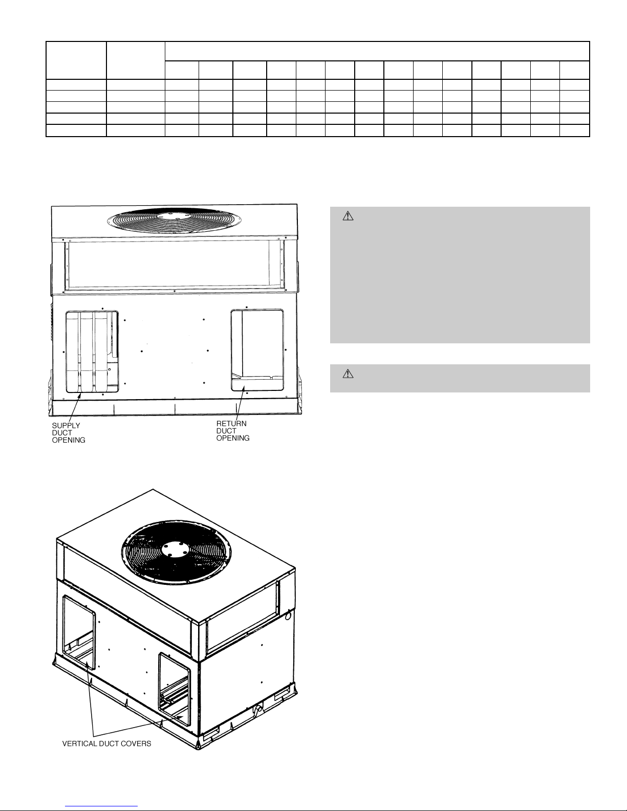
Table 3 — Maximum Gas Flow Capacity*
NOMINAL
IRON PIPE,
SIZE
(in.)
INTERNAL
DIAMETER
(in.)
LENGTH OF PIPE, FT†
10 20 30 40 50 60 70 80 90 100 125 150 175 200
1
⁄
2
.622 175 120 97 82 73 66 61 57 53 50 44 40 — —
3
⁄
4
.824 360 250 200 170 151 138 125 118 110 103 93 84 77 72
1 1.049 680 465 375 320 285 260 240 220 205 195 175 160 145 135
1
1
⁄
4
1.380 1400 950 770 600 580 530 490 460 430 400 360 325 300 280
1
1
⁄
2
1.610 2100 1460 1180 990 900 810 750 690 650 620 550 500 460 430
*Capacity of pipe in cu ft of gas per hr for gas pressure of 0.5 psig or less. Pressure drop of 0.5-in. wg (based on
a 0.60 specific gravity gas). Refer to Table C-4, National Fire Protection Association NFPA 54.
†This length includes an ordinary number of fittings.
X. STEP 10 — INSTALL ELECTRICAL CONNECTIONS
WARNING:
The unit cabinet must have an uninterrupted, unbroken electrical ground to minimize the possibility of personal injury if an electrical fault should
occur .This ground may consist of an electrical wire connected to the unit ground lug in the control compartment, or conduit approved for electrical ground when
installed in accordance with NEC (National Electrical
Code) ANSI/NFPA (latest edition) (in Canada, Canadian Electrical Code CSA [Canadian Standards Association] C22.1) and local electrical codes. Do not use gas
piping as an electrical ground. Failure to adhere to this
warning could result in personal injury or death.
CAUTION:
Failure to follow these precautions could
result in damage to the unit being installed:
1. Make all electrical connections in accordance with NEC
ANSI/NFP A(latest edition) and local electrical codes governing such wiring. In Canada, all electrical connections must be in accordance with CSA standard C22.1
Canadian Electrical Code Part 1 and applicable local codes.
Refer to unit wiring diagram.
2. Use only copper conductor for connections between fieldsupplied electrical disconnect switch and unit. DO NOT
USE ALUMINUM WIRE.
3. Be sure that high-voltage power to unit is within operating voltage range indicated on unit rating plate.
4. Do not damage internal components when drilling through
any panel to mount electrical hardware, conduit, etc. On
3-phase units, ensure phases are balanced within 2%.
Consult local power company for correction of improper
voltage and/or phase imbalance.
A. High-Voltage Connections
The unit must have a separate electrical service with a fieldsupplied, waterproof, disconnect switch mounted at, or within
sight from, the unit. Refer to the unit rating plate for maximum fuse/circuit breaker size and minimum circuit amps (ampacity) for wire sizing. See Tables 4 and 5 for electrical data.
The field-supplied disconnect switch box may be mounted on
the unit over the high-voltage inlet hole when the standard
power and low-voltage entry points are used. See Fig. 2 and
3 for acceptable location.
See unit wiring label and Fig. 11 for reference when making
high voltage connections. Proceed as follows to complete the
high-voltage connections to the unit.
Fig. 9 — Supply and Return Duct Openings
Fig. 10 — Vertical Duct Cover Removed
—11—
Page 12
Single phase units:
1. Run the high-voltage (L1, L2) and ground leads into the
control box.
2. Connect ground lead to chassis ground connection.
3. Connect L1 to pressure lug connection 11 of the compressor contactor.
4. Connect L2 to pressure lug connection 23 of the compressor contactor.
Three phase units:
1. Run the high-voltage (L1, L2, L3) and ground leads into
the control box.
2. Connect ground lead to chassis ground connection.
3. Locate the black and yellow wires connected to the lines
side of the contactor.
4. Connect field L1 to black wire on connection 11 of the
compressor contactor.
5. Connect field wire L2 to yellow wire on connection 13 of
the compressor contactor.
6. Connect field wire L3 to blue wire from compressor.
B. Special Procedures for 208-v Operation
WARNING:
Make sure that the gas supply then the
power supply to the unit is switched OFF before making any wiring changes. Electrical shock can cause personal injury or death.
C. Control Voltage Connections
NOTE: Do not use any type of power-stealing thermostat. Unit
control problems may result.
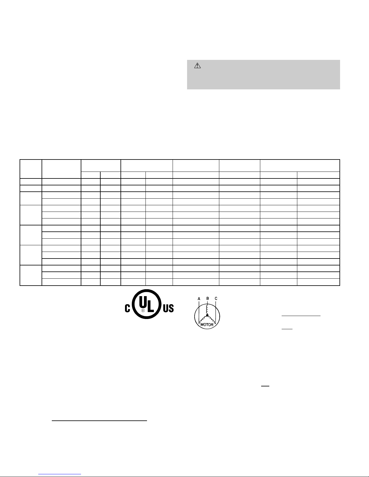
Table 4 — Electrical Data — Unit 582A
UNIT
SIZE
582A
V-PH-Hz
VOLTAGE
RANGE
COMPRESSOR
OUTDOOR FAN
MOTOR
INDOOR FAN
MOTOR
POWER SUPPLY FUSE OR
HACR BRKR
Min Max RLA LRA FLA FLA MCA MOCP*
018 208/230-1-60 187 253 9.0 45.0 0.8 1.8 13.9 20
024 208/230-1-60 187 253 12.8 61.0 0.8 2.0 18.8 30
030
208/230-1-60 187 253 14.4 73.0 0.8 2.0 20.8 30
208/230-3-60 187 253 12.6 68.0 0.8 2.0 13.2 20
036
208/230-1-60 187 253 15.1 81.0 1.6 3.6 24.1 35
208/230-3-60 187 253 10.9 78.0 1.6 3.6 18.8 25
460-3-60 414 506 5.8 40.0 0.9 1.9 10.1 15
042
208/230-1-60 187 253 18.6 105.0 1.6 3.8 27.5 45
208/230-3-60 187 253 10.7 85.0 1.6 3.8 18.8 25
460-3-60 414 506 5.3 42.0 0.9 2.0 9.5 15
048
208-230/1/60 197 253 25.3 131.0 1.6 3.8 37.0 60
208/230-3-60 187 253 13.5 108.0 1.6 3.8 22.3 35
460-3-60 414 506 6.7 47.5 0.9 2.0 11.3 15
060
208/230-1-60 187 253 28.9 147.0 1.6 6.2 43.9 60
208/230-3-60 187 253 18.6 125.0 1.6 6.2 31.1 45
460-3-60 414 506 8.5 66.5 0.9 3.2 14.7 20
LEGEND
FLA — Full Load Amps
HACR — Heating, Air Conditioning and
Refrigeration
LRA — Locked Rotor Amps
MCA — Minimum Circuit Amps
MOCP — Maximum Overcurrent Protection
RLA — Rated Load Amps
*Fuse or HACR Breaker.
NOTES:
1. In compliance with NEC (National Electrical Code) requirements for
multimotor and combination load equipment (refer to NEC
Articles 430 and 440), the overcurrent protective device for the unit
shall be fuse or HACR breaker. The CGA (Canadian Gas
Association) units may be fuse or circuit breaker.
2. Minimum wire size is based on 60 C copper wire. If other than
60 C wire is used, or if length exceeds wire length in table,
determine size from NEC.
3. Unbalanced 3-Phase Supply Voltage
Never operate a motor where a phase imbalance in supply voltage is
greater than 2%.
Use the following formula to determine the percent-
age of voltage imbalance.
% Voltage imbalance
max voltage deviation from average voltage
= 100 x
average voltage
EXAMPLE: Supply voltage is 460-3-60.
AB = 452 v
BC = 464 v
AC = 455 v
452 1 464 1 455
Average Voltage =
3
1371
=
3
= 457
Determine maximum deviation from average voltage.
(AB) 457 − 452=5v
(BC) 464 − 457=7v
(AC) 457 − 455=2v
Maximum deviation is 7 v.
Determine percent of voltage imbalance.
7
% Voltage Imbalance = 100 x
457
= 1.53%
This amount of phase imbalance is satisfactory as it is below the maximum allowable 2%.
IMPORT ANT: If the supply voltage phase imbalance is more than 2%,
contact your local electric utility company immediately.
—12—
Page 13
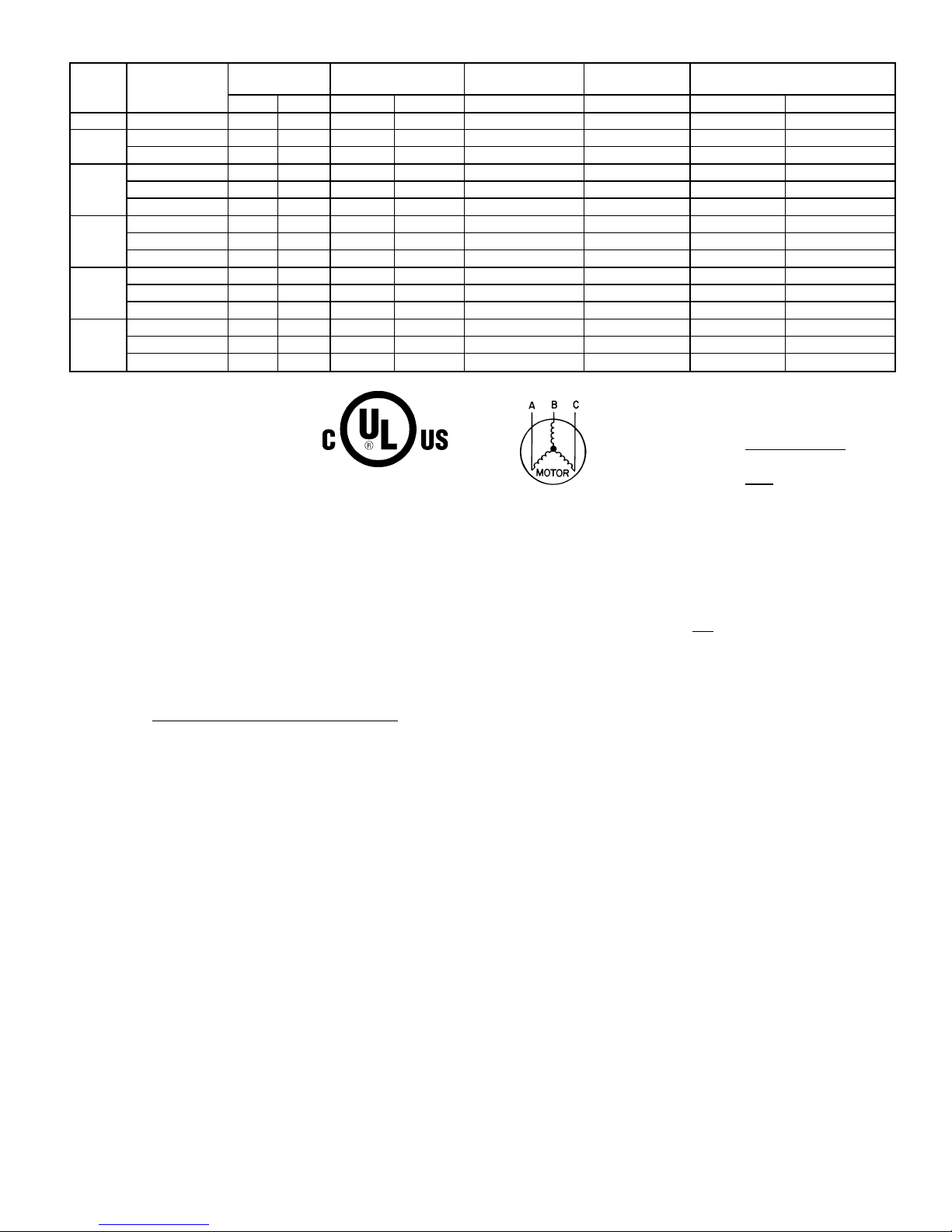
Table 5 — Electrical Data — Unit 538A
UNIT
SIZE
583A
V-PH-Hz
VOLTAGE
RANGE
COMPRESSOR
OUTDOOR FAN
MOTOR
INDOOR FAN
MOTOR
POWER SUPPLY FUSE OR
HACR BRKR
Min Max RLA LRA FLA FLA MCA MOCP*
024 208/230-1-60 187 253 10.3 56.0 0.8 2.0 15.7 25
030
208/230-1-60 187 253 13.5 73.0 0.8 2.1 19.8 30
208/230-3-60 187 253 9.0 63.0 0.8 2.1 14.2 20
036
208/230-1-60 187 253 16.7 97.0 0.8 3.6 25.3 40
208/230-3-60 187 253 11.2 75.0 0.8 3.6 18.4 25
460-3-60 414 506 5.4 37.5 0.9 1.9 9.6 15
042
208/230-1-60 187 253 17.9 104.0 1.6 4.1 28.1 45
208/230-3-60 187 253 12.4 88.0 1.6 4.1 21.2 30
460-3-60 414 506 6.1 44.0 0.9 2.0 10.5 15
048
208/230-1-60 187 253 19.5 104.0 1.6 4.1 30.1 45
208/230-3-60 187 253 12.4 88.0 1.6 4.1 21.2 30
460-3-60 414 506 5.8 44.0 0.9 2.0 10.2 15
060
208/230-1-60 187 253 28.8 169.0 1.6 6.2 43.8 60
208/230-3-60 187 253 17.3 123.0 1.6 6.2 29.4 45
460-3-60 414 506 9.0 62.0 0.9 3.2 15.4 20
LEGEND
FLA — Full Load Amps
HACR — Heating, Air Conditioning
and Refrigeration
LRA — Locked Rotor Amps
MCA — Minimum Circuit Amps
MOCP — Maximum Overcurrent Protection
RLA — Rated Load Amps
*Fuse or HACR Breaker.
NOTES:
1. In compliance with NEC (National Electrical Code) requirements for
multimotor and combination load equipment (refer to NEC
Articles 430 and 440), the overcurrent protective device for the unit
shall be fuse or HACR breaker. The CGA (Canadian Gas
Association) units may be fuse or circuit breaker.
2. Minimum wire size is based on 60 C copper wire. If other than
60 C wire is used, or if length exceeds wire length in table,
determine size from NEC.
3. Unbalanced 3-Phase Supply Voltage
Never operate a motor where a phase imbalance in supply voltage is
greater than 2%.
Use the following formula to determine the percent-
age of voltage imbalance.
% Voltage imbalance
max voltage deviation from average voltage
= 100 x
average voltage
EXAMPLE: Supply voltage is 460-3-60.
AB = 452 v
BC = 464 v
AC = 455 v
452 1 464 1 455
Average Voltage =
3
1371
=
3
= 457
Determine maximum deviation from average voltage.
(AB) 457 − 452=5v
(BC) 464 − 457=7v
(AC) 457 − 455=2v
Maximum deviation is 7 v.
Determine percent of voltage imbalance.
7
% Voltage Imbalance = 100 x
457
= 1.53%
This amount of phase imbalance is satisfactory as it is below the maximum allowable 2%.
IMPORTANT: If the supply voltage phase imbalance is more than
2%, contact your local electric utility company immediately.
—13—
Page 14
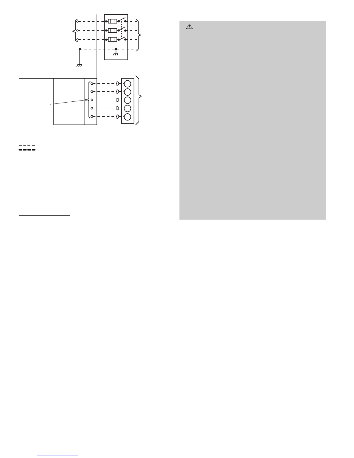
Use no. 18 American Wire Gage (AWG) color-coded, insulated (35 C minimum) wires to make the control voltage connections between the thermostat and the unit. If the thermostat is located more than 100 ft from the unit (as measured
along the control voltage wires), use no. 16 AWG color-coded,
insulated (35 C minimum) wires.
Standard Connection
Remove knockout hole located in the flue panel adjacent to
the control access panel. See Fig. 2 and 3. Remove the rubber
grommet from the installer’s packet (included with unit) and
install grommet in the knockout opening. Provide a drip loop
before running wire through panel.
Run the low-voltage leads from the thermostat, through the
inlet hole, and into unit low-voltage splice box.
Locate five 18-gage wires leaving control box. These lowvoltage connection leads can be identified by the colors red,
green, yellow ,brown, and white. (See Fig. 11.)Ensure the leads
are long enough to be routed into the low-voltage splice box
(located below right side of control box). Stripped yellow wire
is located in connection box. Route leads through hole in bottom of control box and make low-voltage connections as shown
in Fig. 11. Secure all cut wires, so that they do not interfere
with operation of unit.
D. Heat Anticipator Setting
The room thermostat heat anticipator must be properly adjusted to ensure proper heating performance. Set the heat
anticipator, using an ammeter between the W and R terminals to determine the exact required setting.
NOTE: For thermostat selection purposes, use 0.18 amp for
the approximate required setting.
Failure to make a proper heat anticipator adjustment will
result in improper operation, discomfort to the occupants of
the conditioned space, and inefficientenergy utilization; however, the required setting may be changed slightly to provide
a greater degree of comfort for a particular installation.
E. Transformer Protection
The transformer is of the energy-limiting type. It is set to
withstand a 30-second overload or shorted secondary
condition.
PRE-START-UP
WARNING:
Failure to observe the following warn-
ings could result in serious personal injury:
1. Follow recognized safety practices and wear protective goggles when checking or servicing refrigerant
system.
2. Do not operate compressor or provide any electric
power to unit unless compressor terminal cover is in
place and secured.
3. Do not remove compressor terminal cover until all
electrical sources are disconnected.
4. Relieve and recover all refrigerant from system before touching or disturbing anything inside terminal box if refrigerant leak is suspected around compressor terminals.
5. Never attempt to repair soldered connection while
refrigerant system is under pressure.
6. Do not use torch to remove any component. System
contains oil and refrigerant under pressure. To remove a component, wear protective goggles and proceed as follows:
a. Shut off gas supply and then electrical power to
unit.
b. Relieve and reclaim all refrigerant from system
using both high- and low-pressure ports.
c. Cut component connecting tubing with tubing cut-
ter and remove component from unit.
d. Carefully unsweat remaining tubing stubs when
necessary. Oil can ignite when exposed to torch
flame.
Proceed as follows to inspect and prepare the unit for initial
start-up:
1. Remove access panel.
2. Read and follow instructions on all WARNING, CAUTION, and INFORMATIONlabels attached to, or shipped
with, unit.
3. Make the following inspections:
a. Inspect for shipping and handling damages such as
broken lines, loose parts, disconnected wires, etc.
b. Inspect for oil at all refrigerant tubing connections
and on unit base. Detecting oil generally indicates a
refrigerant leak. Leak-test all refrigerant tubing connections using electronic leak detector, halide torch,
or liquid-soap solution. If a refrigerant leak is detected, see Check for Refrigerant Leaks section on
page 15.
c. Inspect all field- and factory-wiring connections. Be
sure that connections are completed and tight.
d. Inspect coil fins. If damaged during shipping and han-
dling, carefully straighten fins with a fin comb.
POWER
SUPPLY
FIELD-SUPPLIED
FUSED DISCONNECT
HIGH VOLTAGE
POWER LEADS
(SEE UNIT WIRING
LABEL)
GND
CONTROL BOX
SPLICE BOX
LOW-VOLTAGE
POWER LEADS
(SEE UNIT
WIRING LABEL)
W
Y
G
R
C
WHT(W1)
YEL(Y)
GRN(G)
RED(R)
BRN(C)
THERMOSTAT
(TYPICAL)
LEGEND
Field Control-Voltage Wiring
Field High-Voltage Wiring
NOTE: Use blue wire for 3-phase units only.
Fig. 11 — High- and Control-Voltage Connections
—14—
Page 15
4. Verify the following conditions:
CAUTION:
Do not purge gas supply into the combustion chamber.Do not use a match or other open flame
to check for gas leaks. Failure to follow this warning
could result in an explosion causing personal injury or
death.
a. Before lighting the unit for the first time, perform
the following: If the gas supply pipe was not purged
before connecting the unit, it will be full of air. It is
recommended that the ground joint union be loosened, and the supply line be allowed to purge until
the odor of gas is detected. Never purge gas lines into
a combustion chamber. Immediately upon detection
of gas odor, retighten the union. Allow 5 minutes to
elapse, then light unit.
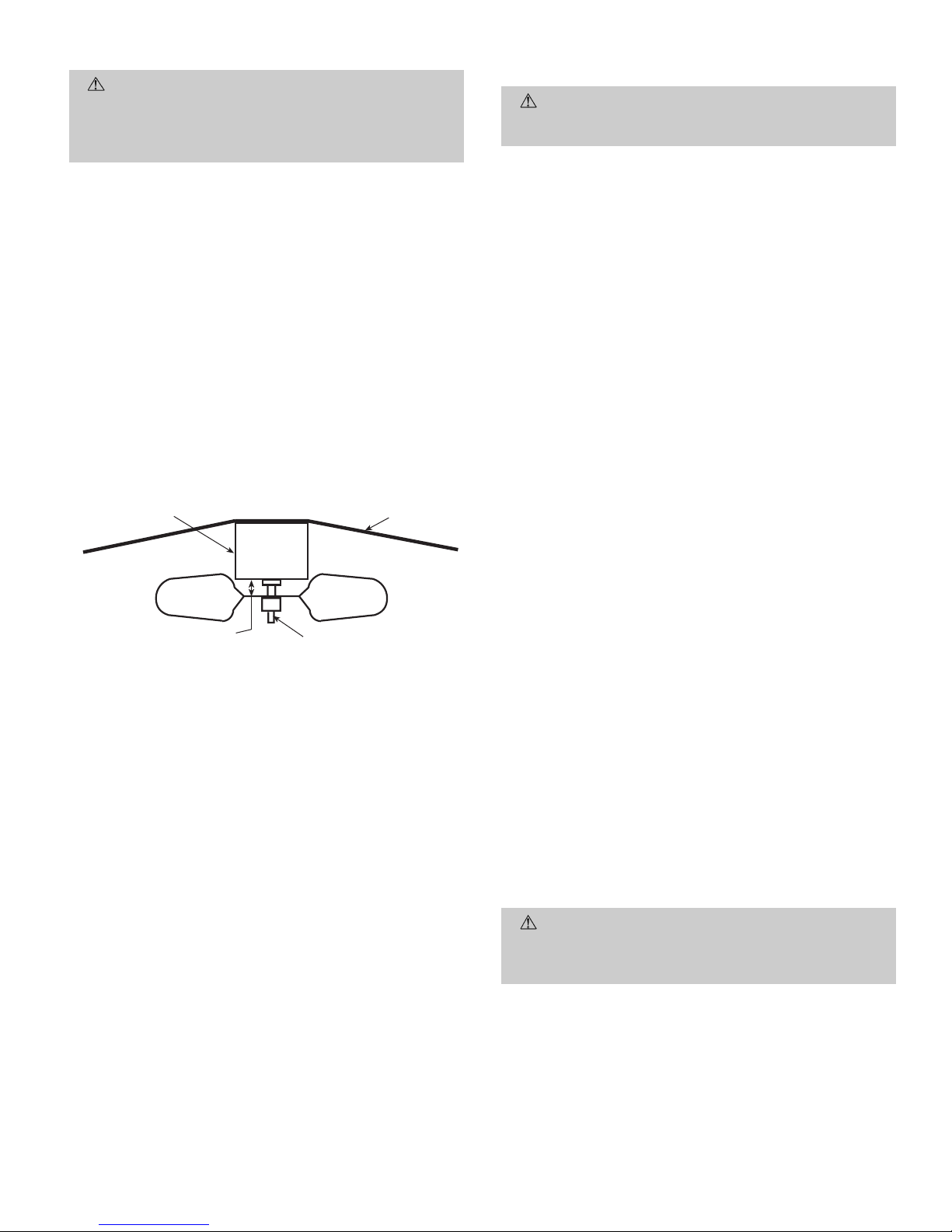
b. Make sure that condenser-fan blade is correctly po-
sitioned in fan orifice. Leading edge of condenser-fan
blade should be
1
⁄2in. maximum from fan orifice (see
Fig. 12).
c. Make sure that air filter(s) is in place.
d. Make sure that condensate drain trap is filled with
water to ensure proper drainage.
e. Make sure that all tools and miscellaneous loose parts
have been removed.
START-UP
I. CHECK FOR REFRIGERANT LEAKS
Proceed as follows to locate and repair a refrigerant leak and
to charge the unit:
1. Locate leak and make sure that refrigerant system pressure has been relieved and recovered from both highand low-pressure ports.
2. Repair leak using Standard Refrigerant Service procedures.
NOTE: Install a filter drier whenever the system has
been opened for repair.
3. Add a small charge of R-22 refrigerant vapor to system
and leak-test unit.
4. Evacuate and recover refrigerant from refrigerant system if additional leaks are not found.
5. Charge unit with R-22 refrigerant, using a volumetriccharging cylinder or accurate scale. Refer to unit rating
plate for required charge. Be sure to add extra refrigerant to compensate for internal volume of filter drier.
II. START UP HEATING SECTION AND MAKE
ADJUSTMENTS
CAUTION:
Complete the required procedures given
in Pre-Start-Up section on page 14 before starting the
unit.
Do not jumper any safety devices when operating the unit.
Make sure that burner orifices are properly aligned. Un-
stable operation may occur when the burner orifices in the
manifold are misaligned.
Follow the lighting instructions on the heating section operation label (located inside the burner or blower access door) to
start the heating section.
NOTE: Make sure that gas supply has been purged, and that
all gas piping has been checked for leaks.
A. Check Heating Control
Start and check the unit for proper heating control operation
as follows. (See furnace lighting instructions located inside
burner or blower access panel.)
1. Place the room thermostat SYSTEM switch in the HEAT
position and the fan switch in the AUTO. position.
2. Set the heating temperature control of the thermostat
above room temperature.
3. The induced-draft motor will start.
4. After a call for heating, the main burner should light
within 5 seconds. If the burners do not light, there is a
22-second delay before another 5-second try .If the burners still do not light, this sequence is repeated. If the
burners do not light within 15 minutes from the initial
call for heat, there is a lockout. Toreset the control, break
the 24-v power to W.
5. The evaporator fan will turn on 45 seconds after the flame
has been established. The evaporator fan will turn off
45 seconds after the thermostat has been satisfied.
B. Check Gas Input
Check gas input and manifold pressure after unit start-up.
(See Table 6.) If adjustment is required proceed as follows.
The rated gas inputs shown in Table 6 are for altitudes from
sea level to 2000 ft above sea level. These inputs are based
on natural gas with a heating value of 1050 Btu/ft
3
at 0.65
specific gravity, or propane gas with a heating value of
2500 Btu/ft
3
at 1.5 specific gravity. For elevations above
2000 ft, reduce input 4% for each 1000 ft above sea level. When
the gas supply being used has a different heating value or
specific gravity, refer to national and local codes, or contact
your distributor to determine the required orifice size.
CAUTION:
These units are designed to consume the
rated gas inputs using the fixed orifices at specified manifold pressures as shown in Table 6. DO NOT REDRILL
THE ORIFICES UNDER ANY CIRCUMSTANCES.
FAN GRILLE
MOTOR
1/8" MAX BETWEEN
MOTOR AND FAN HUB
MOTOR SHAFT
Fig. 12 — Fan Blade Clearance
—15—
Page 16
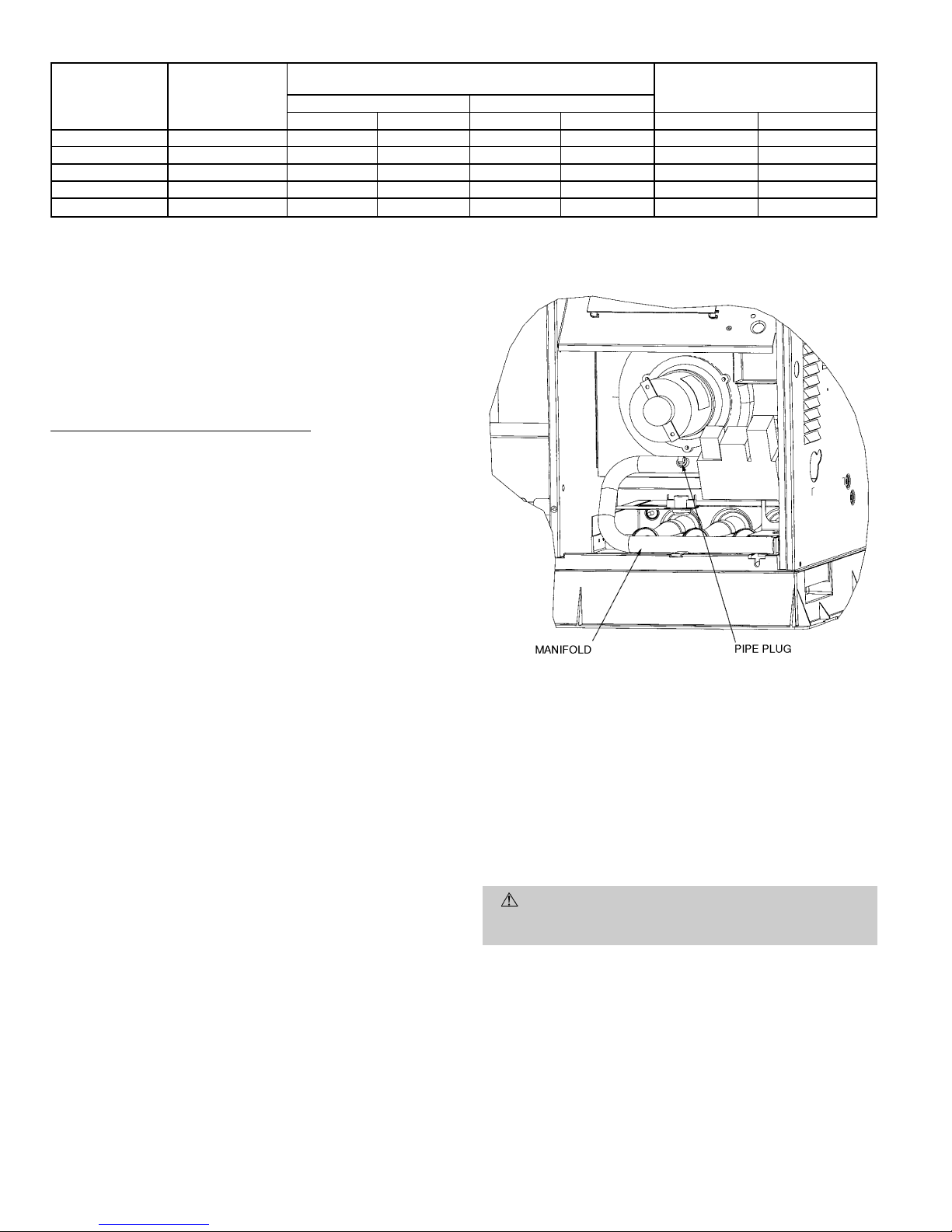
Table 6 — Heating Inputs
HEATING
INPUT
(Btuh*)
NUMBER
OF
ORIFICES
GAS SUPPLY PRESSURE
(in. wg)
MANIFOLD
PRESSURE
(in. wg)
Natural Propane†
Min Max Min Max Natural Propane†
40,000 2 4.0 13.0 4.0 13.0 3.5 3.5
60,000 2 4.0 13.0 4.0 13.0 3.5 3.5
90,000 3 4.0 13.0 4.0 13.0 3.5 3.4
115,000 3 4.0 13.0 4.0 13.0 3.5 3.7
130,000 3 4.0 13.0 4.0 13.0 3.5 3.5
*When a unit is converted to propane, different size orifices must be used. See separate natural-
to-propane conversion kit instructions.
†Based on altitudes from sea level to 2000 ft above sea level. For altitudes above 2000 ft, reduce
input rating 4% for each additional 1000 ft above sea level. In Canada, from 2000 ft above sea
level to 4500 ft above sea level, derate the unit 10%.
C. Adjust Gas Input
The gas input to the unit is determined by measuring the
gas flow at the meter or by measuring the manifold pressure.
Measuring the gas flow at the meter is recommended for natural gas units. The manifold pressure must be measured to
determine the input of propane gas units.
Measure Gas Flow (Natural Gas Units)
Minor adjustment to the gas flow can be made by changing
the manifold pressure. The manifold pressure must be maintained between 3.4 and 3.6 in. wg. If larger adjustments are
required, change main burner orifices following the recommendations of national and local codes.
NOTE: All other appliances that use the same meter must
be turned off when gas flow is measured at the meter.
Proceed as follows:
1. Turn off gas supply to unit.
2. Remove pipe plug on manifold (see Fig. 13) then connect manometer at this point. Turn on gas to unit.
3. Record number of seconds for gas meter test dial to make
one revolution.
4. Divide number of seconds in Step 3 into 3600 (number
of seconds in one hour).
5. Multiply result of Step 4 by the number of cu ft shown
for one revolution of test dial to obtain cu ft of gas flow
per hour.
6. Multiply result of Step 5 by Btu heating value of gas to
obtain total measured input in Btuh. Compare this value
with heating input shown in Table 6. (Consult the local
gas supplier if the heating value of gas is not known.)
EXAMPLE: Assume that the size of test dial is 1 cu ft, one
revolution takes 32 seconds, and the heating value of the gas
is 1050 Btu/ft
3
. Proceed as follows:
1. 32 seconds to complete one revolution.
2. 3600 ÷ 32 = 112.5.
3. 112.5x1=112.5 ft
3
of gas flow/hr.
4. 112.5 x 1050 = 118,125 Btuh input.
If the desired gas input is 115,000 Btuh, only a minor change
in the manifold pressure is required.
Observe manifold pressure and proceed as follows to adjust
gas input:
1. Remove cover screw over regulator adjustment screw on
gas valve.
2. Turn regulator adjustment screw clockwise to increase
gas input, or turn regulator adjustment screw counterclockwise to decrease input. Manifold pressure must be
between 3.4 and 3.6 in. wg.
WARNING:
Unsafe operation of the unit may result
if manifold pressure is outside this range. Personal injury or unit damage may result.
3. Replace cover screw cap on gas valve.
4. Turn off gas supply to unit. Remove manometer from
pressure tap and replace pipe plug on gas valve. Turn
on gas to unit and check for leaks.
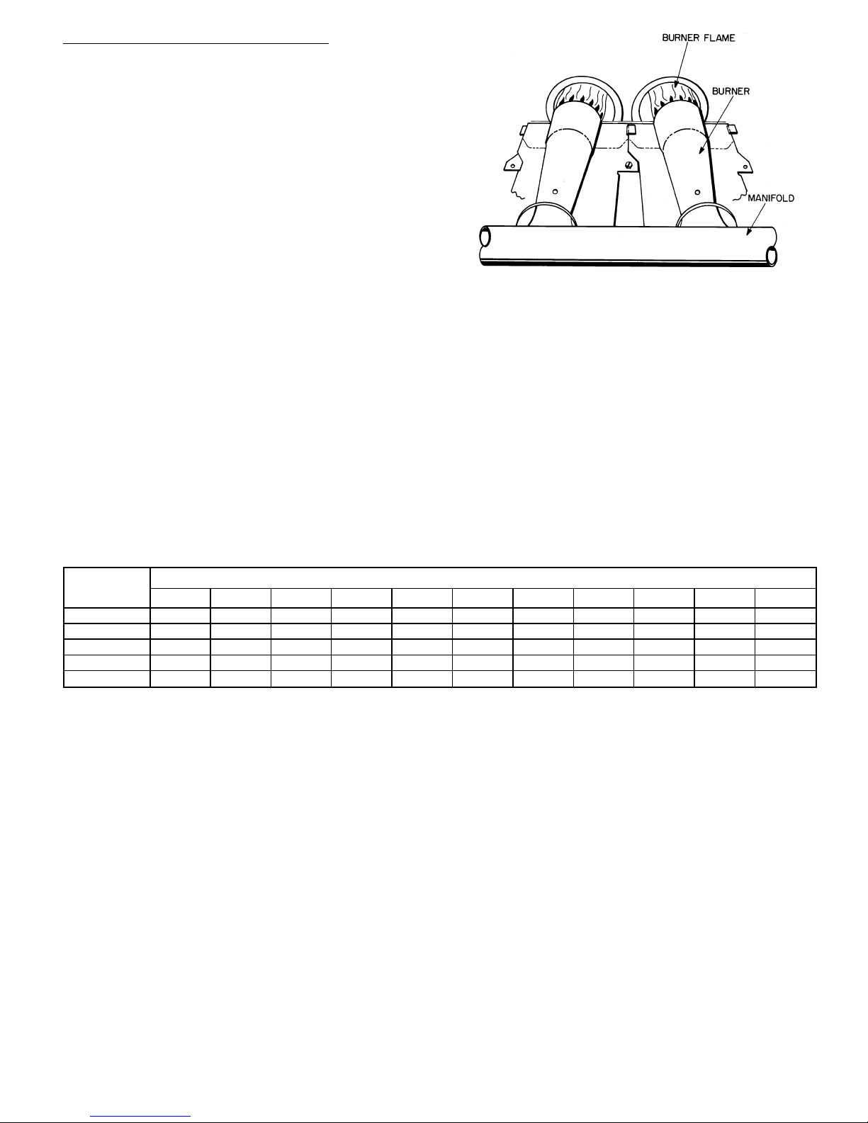
Fig. 13 — Burner Assembly
—16—
Page 17
Measure Manifold Pressure (Propane Units)
The main burner orifices on a propane gas unit are sized for
the unit rated input when the manifold pressure reading
matches the level specified in Table 6.
Proceed as follows to adjust gas input on a propane gas unit:
1. Turn off gas to unit.
2. Remove pipe plug on manifold (see Fig. 13), then connect manometer at this point.
3. Turn on gas to unit.
4. Remove cover screw over regulator adjustment screw on
gas valve.
5. Adjust regulator adjustment screw to the correct manifold pressure, as specified in Table 6. Turn adjusting
screw clockwise to increase manifold pressure, or turn
adjusting screw counterclockwise to decrease manifold
pressure.
6. Replace cover screw.
7. Turn off gas to unit. Remove manometer from pressure
tap. Replace pipe plug on gas valve, then turn on gas to
unit. Check for leaks.
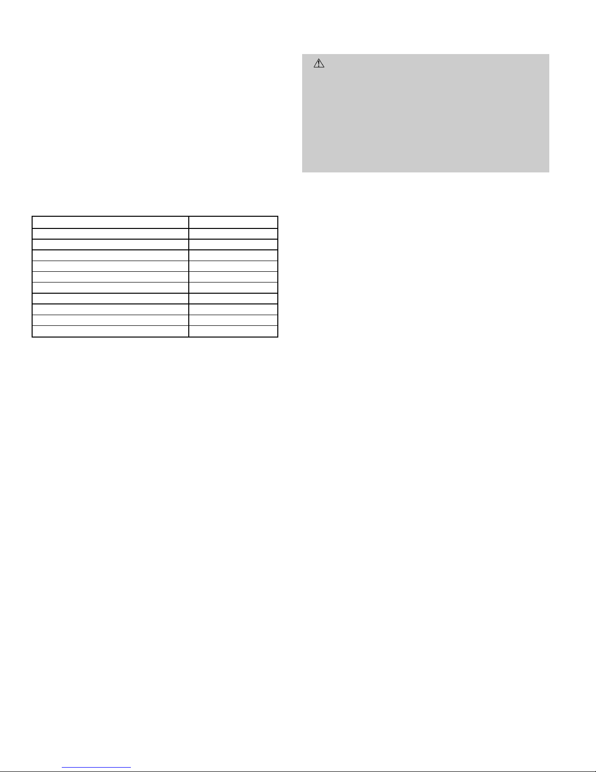
D. Check Burner Flame
With burner access panel removed, observe the unit heating
operation. Watch the burner flames to see if they are light
blue and soft in appearance, and that the flames are approximately the same for each burner .Propane will have blue flame
with yellow tips. See Fig. 14. Refer to Maintenance section
for information on burner removal.
E. Airflow and Temperature Rise
The heating section for each size unit is designed and approved for heating operation within the temperature-rise range
stamped on the unit rating plate.
Table 7 shows the approved temperature-rise range for each
heating input, and the air delivery cfm at various temperature rises. The heating operation airflow must produce a temperature rise that falls within the approved range.
Refer to Indoor Airflow and Airflow Adjustments section on
page 22 to adjust heating airflow when required.
Table 7 — Air Delivery (Cfm) at Indicated Temperature Rise and Rated Heating Input
HEATING
INPUT
(Btuh)
TEMPERATURE RISE °F
20 25 30 35 40 45 50 55 60 65 70
40,000 1500 1200 1000 857 750 667 600 545 500 — —
60,000 2250 1800 1500 1286 1125 1000 900 818 750 692 —
90,000 — — 2250 1929 1688 1500 1350 1227 1125 1038 964
115,000 — — — 2464 2156 1917 1725 1568 1438 1327 1232
130,000 — — — 2786 2438 2167 1950 1773 1625 1500 —
NOTE: Dashed areas do not fall within the approved temperature rise range of the unit.
Fig. 14 — Monoport Burners
—17—
Page 18
F. Heating Sequence of Operation
See Fig. 15-17 and unit wiring label.
On a call for heating, terminal ‘‘W’’ of the thermostat is en-
ergized, starting the induced-draft motor. When the halleffect sensor on the induced-draft motor senses that it has
reached the required speed, the burner sequence begins. This
function is performed by the integrated gas control (IGC). The
evaporator-fan motor is energized 45 seconds after flame is
established. When the thermostat is satisfied and ‘‘W’’is deenergized, the burners stop firing and the evaporator-fan motor
shuts off after a 45-second time-off delay.
An LED (light-emitting diode) indicator is provided on the
control board to monitor operation. The control board is located by removing the burner access panel. During normal
operation, the LED is continuously on. See Table 8 for error
codes.
Table 8 — LED Indications
ERROR CODE LED INDICATION
Normal Operation On
Hardware Failure Off
Fan On/Off Delay Modified 1 Flash
Limit Switch Fault 2 Flashes
Flame Sense Fault 3 Flashes
Four Consecutive Limit Switch Faults 4 Flashes
Ignition Lockout Fault 5 Flashes
Induced-Draft Motor Fault 6 Flashes
Rollout Switch Fault 7 Flashes
Internal Control Fault 8 Flashes
NOTES:
1. There is a 3-second pause between error code displays.
2. If more than one error code exists, all applicable error codes will be
displayed in numerical sequence.
3. This chart is on the wiring diagram located inside the burner
access panel.
G. Limit Switches
Normally closed limit switch (LS) completes the control circuit through the thermostat R circuit. Should the leaving-air
temperature rise above the maximum allowable temperature, the limit switch opens and the R control circuit ‘‘breaks.’’
Any interruption in the R control circuit instantly closes the
gas valve and stops gas flow to the burners and pilot. The
blower motor continues to run until LS resets.
When the air temperature at the limit switch drops to the
low-temperature setting of the limit switch, the switch closes
and completes the R control circuit. The electric-spark ignition system cycles and the unit returns to normal heating
operation.
H. Auxiliary Limit Switch — Rollout
The function of the switch is to close the main gas valve in
the event of flame rollout. The switch is located above the
main burners. When the temperature at the auxiliary switch
reaches the maximum allowable temperature, the R control
circuit trips, closing the gas valve and stopping gas flow to
the burners. The indoor (evaporator) fan motor (IFM) and induced draft motor continue to run until switch is reset.
III. START UP COOLING SECTION AND MAKE
ADJUSTMENTS
CAUTION:
Complete the required procedures given
in the Pre-Start-Up section on page 14 before starting
the unit.
Do not jumper any safety devices when operating the
unit.
Do not operate the compressor when the outdoor temperature is below 40 F (unless accessory low-ambient
kit is installed).
Do not rapid-cycle the compressor. Allow 5 minutes between ‘‘on’’ cycles to prevent compressor damage.
A. Checking Cooling Control Operation
Start and check the unit for proper cooling control operation
as follows:
1. Place room thermostat SYSTEM switch in OFF position. Observe that blower motor starts when FAN switch
is placed in ON position and shuts down when FANswitch
is placed in AUTO. position.
2. Place SYSTEM switch in COOL position and FAN switch
in AUTO. position. Set cooling control below room temperature. Observe that compressor, condenser fan, and
evaporator blower motors start. Observe that cooling cycle
shuts down when control setting is satisfied. The evaporator fan will continue to run for 30 seconds.
3. When using an auto.-changeover room thermostat, place
both SYSTEM and FAN switches in AUTO. positions.
Observe that unit operates in Heating mode when temperature control is set to ‘‘call for heating’’ (above room
temperature) and operates in Cooling mode when temperature control is set to ‘‘call for cooling’’ (below room
temperature).
IMPORT ANT: Three-phase, scroll compressor units (582A048
and 583A030-060) are direction-oriented. These units must
be checked to ensure proper compressor 3-phase power lead
orientation. If not corrected within 5 minutes, the internal
protector will shut off the compressor. The 3-phase power leads
to the unit must be reversed to correct rotation. When turning backwards, scroll compressors emit elevated noise levels,
and the difference between compressor suction and discharge pressures may be dramatically lower than normal.
(Text continued on page 22.)
—18—
Page 19
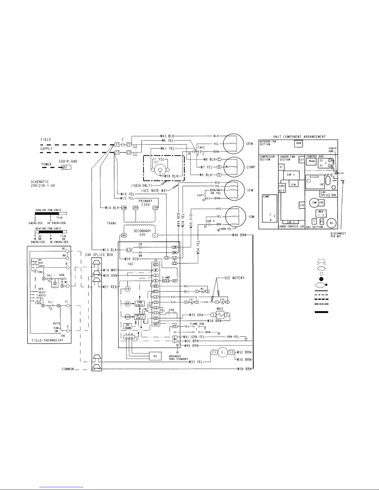
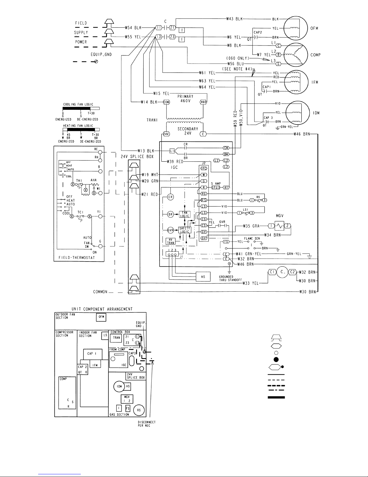
Fig. 15 — 208/230-1-60 Wiring Diagram, Units 582A and 583A
LEGEND
BR — Blower Relay
C—Contactor
CAP — Capacitor
COMP — Compressor Motor
CR — Combustion Relay
EQUIP — Equipment
FS — Fusible Link
FU — Fuse
GND — Ground
GVR — Gas Valve Relay
HS — Hall Effect Sensor
HV
TRAN
— High Voltage Transformer
I—Ignitor
IDM — Induced-Draft Motor
IFM — Indoor-Fan Motor
IGC — Integrated Gas Unit
Controller
LS — Limit Switch
MGV — Main Gas Valve
NEC — National Electrical Code
OFM — Outdoor-Fan Motor
QT — Quadruple Terminal
RS — Rollout Switch
ST — Thermistor Start
TRAN — Transformer
Field Splice
Terminal (Marked)
Terminal (Unmarked)
Splice
Splice (Marked)
Factory Wiring
Field Control Wiring
Field Power Wiring
Accessory or Optional
Wiring
To Indicate Common
Potential Only, Not
to Represent Wiring
NOTES:
1. If any of the original wires furnished are replaced, they must be replaced with
type 90 degree C wire or its equivalent.
2. See price pages for thermostat and subbases.
3. Use 75 degree copper conductors for field installation.
4. For high speed IFM, disconnect RED wire from IGC:BM and connect BLK wire
from IFM. For medium speed, disconnect RED wire from IGC:BM and connect
BLU wire from IFM.
5. Models 582A018-042 and 583A024-036 have LS1 and LS2 wired in series.
Models 582A048,060 and 583A042-060 have LS1 only.
—19—
Page 20
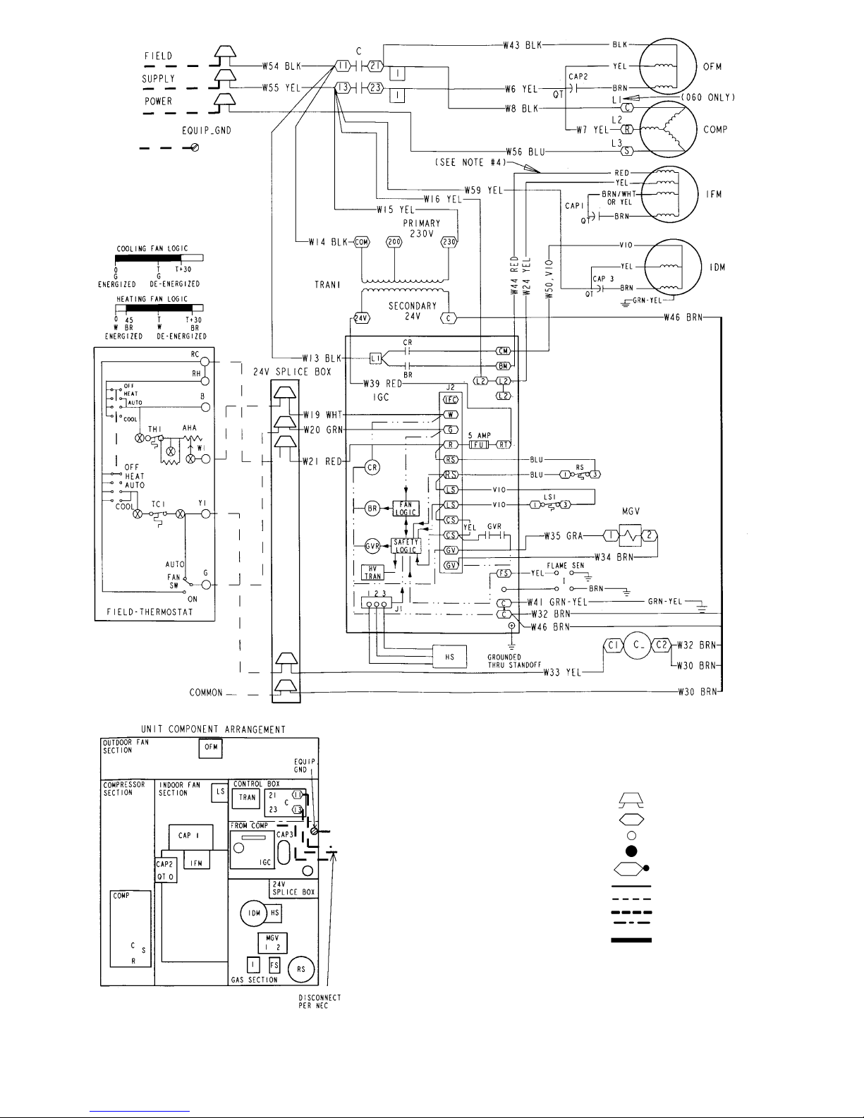
LEGEND
AHA — Adjustable Heat Anticipator
BR — Blower Relay
C—Contactor
CAP — Capacitor
COMP — Compressor Motor
CR — Combustion Relay
CS — Centrifugal Switch
EQUIP — Equipment
FS — Fusible Link
FU — Fuse
GND — Ground
GV — Gas Valve
GVR — Gas Valve Relay
HS — Hall Effect Sensor
HV — High Voltage
I—Ignitor
IDM — Induced-Draft Motor
IFC — Indoor-Fan Contactor
IFM — Indoor-Fan Motor
IGC — Integrated Gas Unit Controller
L1 — Line
LS — Limit Switch
LS1 — Limit Switch
MGV — Main Gas Valve
NEC — National Electrical Code
OFM — Outdoor-Fan Motor
QT — Quadruple Terminal
RS — Rollout Switch
SEN — Sensor
SW — Switch
TRAN — Transformer
Field Splice
Terminal (Marked)
Terminal (Unmarked)
Splice
Splice (Marked)
Factory Wiring
Field Control Wiring
Field Power Wiring
Accessory or Optional Wiring
To Indicate Common Potential
Only, Not to Represent Wiring
NOTES:
1. If any of the original wires furnished are replaced, they must be replaced with type 90 degree C wire or its equivalent.
2. See price pages for thermostat and subbases.
3. Use 75 degree C copper conductors for field installation.
4. For high speed IFM, disconnect RED wire from IGC:BM and connect BLK wire from IFM.
For medium speed, disconnect RED wire from IGC:BM and connect BLU wire from IFM.
Fig. 16 — 208/230-3-60 Wiring Diagram, Units 582A and 583A
—20—
Page 21
LEGEND
AHA — Adjustable Heat Anticipator
BR — Blower Relay
C—Contactor
CAP — Capacitor
COMP — Compressor Motor
CR — Combustion Relay
CS — Centrifugal Switch
EQUIP — Equipment
FS — Fusible Link
FU — Fuse
GND — Ground
GV — Gas Valve
GVR — Gas Valve Relay
HS — Hall Effect Sensor
HV — High Voltage
I—Ignitor
IDM — Induced-Draft Motor
IFC — Indoor-Fan Contactor
IFM — Indoor-Fan Motor
IGC — Integrated Gas Unit Controller
L1 — Line
LS — Limit Switch
LS1 — Limit Switch
MGV — Main Gas Valve
NEC — National Electrical Code
OFM — Outdoor-Fan Motor
QT — Quadruple Terminal
RS — Rollout Switch
SEN — Sensor
SW — Switch
TRAN — Transformer
Field Splice
Terminal (Marked)
Terminal (Unmarked)
Splice
Splice (Marked)
Factory Wiring
Field Control Wiring
Field Power Wiring
Accessory or Optional Wiring
To Indicate Common Potential
Only, Not to Represent Wiring
NOTES:
1. If any of the original wires furnished are replaced, they must be replaced with type 90 degree C wire or its equivalent.
2. See price pages for thermostat and subbases.
3. Use 75 degree C copper conductors for field installation.
4. On all units for G.E. motors wire as follows: For high speed IFM, disconnect RED wire from
IGC:BM and connect BLK wire from IFM. For medium speed, disconnect RED wire from
IGC:BM and connect BLU wire from IFM.
Fig. 17 — 460-3-60 Wiring Diagram, Units 582A and 583A
—21—
Page 22
B. Checking and Adjustment Refrigerant Charge
The refrigerant system is fully charged with R-22 refrigerant, tested, and factory-sealed.
NOTE: Adjustment of the refrigerant charge is not required
unless the unit is suspected of not having the proper R-22
charge.
A superheat charging chart is attached to the outside of the
service access panel. The chart includes the required suction
line temperature at given suction line pressures and outdoor
ambient temperatures.
An accurate superheat, thermocouple- or thermistor-typethermometer, a sling psychrometer, and a gage manifold are required when using the superheat charging method for evaluating the unit charge. Do not use mercury or small dial-type
thermometers because they are not adequate for this type of
measurement.
CAUTION:
When evaluating the refrigerant charge,
an indicated adjustment to the specified factory charge
must always be very minimal. If a substantial adjustment is indicated, an abnormal condition exists somewhere in the cooling system, such as insufficient airflow
across either coil or both coils.
Proceed as follows:
1. Remove caps from low- and high-pressure service
fittings.
2. Using hoses with valve core depressors, attach low- and
high-pressure gage hoses to low- and high-pressure service fittings, respectively.
3. Start unit in Cooling mode and let unit run until system pressures stabilize.
4. Measure and record the following:
a. Outdoor ambient-air temperature (F db).
b. Evaporator inlet-air temperature (F wb).
c. Suction-tube temperature (F) at low-side service
fitting.
d. Suction (low-side) pressure (psig).
5. Using ‘‘Cooling Charging Charts’’ compare outdoor-air
temperature (F db) with the suction line pressure (psig)
to determine desired system operating suction line temperature. See Fig. 18-30.
6. Compare actual suction-tube temperature with desired
suction-tube temperature. Using a tolerance of ±3° F ,add
refrigerant if actual temperature is more than 3° F higher
than proper suction-tube temperature, or remove refrigerant if actual temperature is more than 3° F lower than
required suction-tube temperature.
NOTE: If the problem causing the inaccurate readings is a
refrigerant leak, refer to Check for Refrigerant Leaks section
on page 15.
C. Indoor Airflow and Airflow Adjustments
CAUTION:
For cooling operation, the recommended
airflow is 350 to 450 cfm for each 12,000 Btuh of rated
cooling capacity. For heating operation, the airflow must
produce a temperature rise that falls within the range
stamped on the unit rating plate.
Table 7 shows the temperature rise at various airflow rates.
Tables 9 and 10 show both heating and cooling airflows at
various external static pressures. Refer to these tables to determine the airflow for the system being installed. See
Tables 11A and 11B for wet coil pressure drop.
NOTE: Be sure that all supply- and return-air grilles are open,
free from obstructions, and adjusted properly.
WARNING:
Shut off gas supply then disconnect electrical power to the unit before changing blower speed.
Electrical shock can cause personal injury or death.
Airflow can be changed by changing the lead connections of
the blower motor.
Unit 582A two- or three-speed motors (except size 030) are
factory wired for low speed operation. Unit 582A030 is factory wired for medium speed.
All 583A units are factory wired for low speed and may need
to be wired for medium or high speed in the field.
For 208/230-v
The motor leads are color-coded as follows:
3-SPEED 2-SPEED
black = high speed black = high speed
blue = medium speed red = low speed
red = low speed
To change the speed of the blower motor (BM), remove the
fan motor speed leg lead from the blower relay (BR). This
wire is attached to terminal BM for single-phase and 3-phase
units. To change the speed, remove and replace with lead for
desired blower motor speed. Insulate the removed lead to avoid
contact with chassis parts.
For 460-v GE Motors
The motor leads are color coded as follows:
3-SPEED 2-SPEED
black = high black = high
violet = jumper blue = jumper
orange = medium red = low
red = low
To change the speed of the blower motor (BM), remove fan
motor speed lead from the blower relay (BR) and replace with
the lead for the desired blower motor speed. The motor speed
lead is attached to terminal BM. For low and medium speeds
black must be connected to the jumper wire. Insulate re-
moved lead end to avoid contact with chassis parts. To select
high speed on 460-v GE motors, separate the black (female
quick connect [QC]) from the jumper lead (male quick connect [QC]) and connect the black lead to the BR. Insulate the
jumper to avoid contact with any chassis parts.
—22—
Page 23
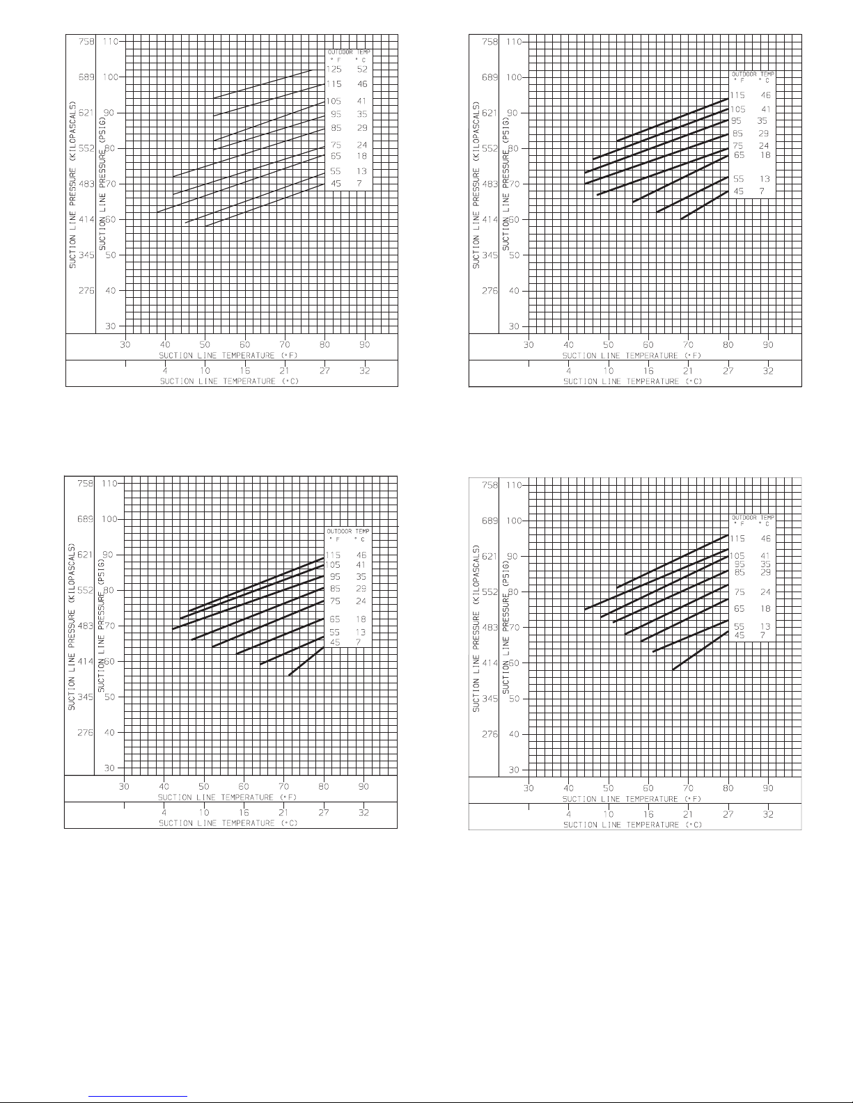
Fig. 18 — Cooling Charging Chart,
582A018 Units
Fig. 19 — Cooling Charging Chart,
582A024 Units
Fig. 20 — Cooling Charging Chart,
582A030 Units
Fig. 21 — Cooling Charging Chart,
582A036 Units
—23—
Page 24
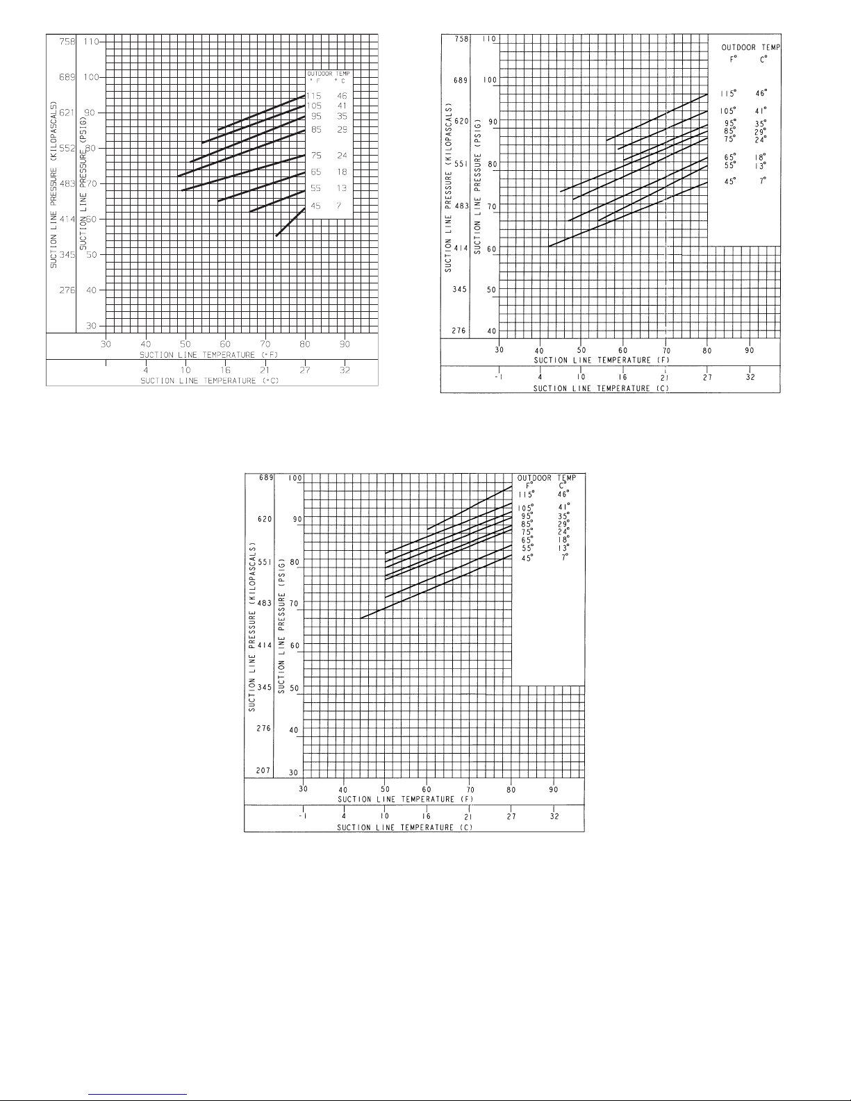
Fig. 21 — Cooling Charging Chart,
582A042 Units
Fig. 24 — Cooling Charging Chart,
582A060 Units
Fig. 23 — Cooling Charging Chart,
582A048 Units
—24—
Page 25
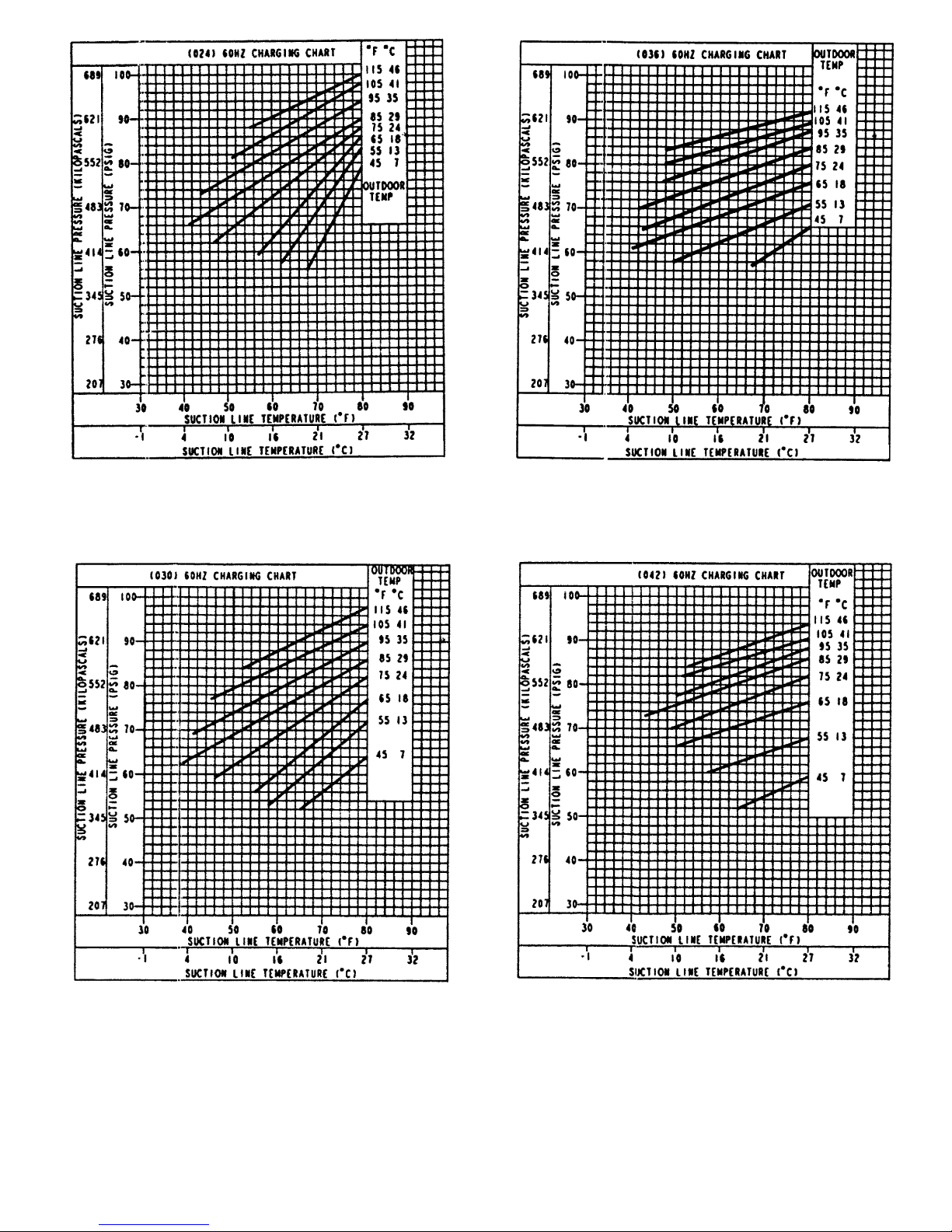
Fig. 25 — Cooling Charging Chart,
583A024 Units
Fig. 26 — Cooling Charging Chart,
583A030 Units
Fig. 27 — Cooling Charging Chart,
583A036 Units
Fig. 28 — Cooling Charging Chart,
583A042 Units
—25—
Page 26
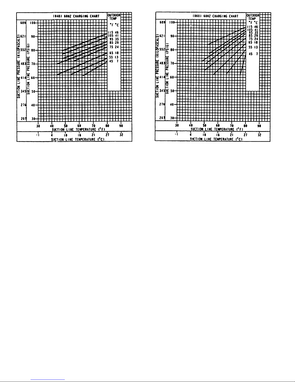
Fig. 29 — Cooling Charging Chart,
583A048 Units
Fig. 30 — Cooling Charging Chart,
583A060 Units
—26—
Page 27
Table 9 — Dry Coil Air Delivery* — Horizontal and Downflow Discharge —
Unit 582A018-060 (Deduct 10% for 208 Volts)
230 AND 460 VOLT
Unit
582A
Motor
Speed
External Static Pressure (in. wg)
0.0 0.1 0.2 0.3 0.4 0.5 0.6 0.7 0.8 0.9 1.0
018
Low
Watts 227 212 196 177 165 153 — — — — —
Cfm 1082 1016 929 796 668 428 — — — — —
Med
Watts ————————— — —
Cfm ————————— — —
High
Watts 287 275 266 253 242 234 226 — — — —
Cfm 1270 1179 1054 932 780 633 372 — — — —
024
Low
Watts 280 275 270 267 264 262 260 — — — —
Cfm 950 880 825 750 670 580 400 — — — —
Med
Watts 380 375 365 360 355 350 344 335 312 — —
Cfm 1220 1150 1090 1025 970 860 760 620 450 — —
High
Watts 485 475 470 460 455 445 437 430 415 385 —
Cfm 1475 1440 1350 1275 1200 1125 1025 925 750 400 —
030
Low
Watts 280 275 270 267 264 262 260 — — — —
Cfm 950 880 825 750 670 580 400 — — — —
Med
Watts 380 375 365 360 355 350 344 335 312 — —
Cfm 1220 1150 1090 1025 970 860 760 620 450 — —
High
Watts 485 475 470 460 455 445 437 430 415 385 —
Cfm 1475 1440 1350 1275 1200 1125 1025 925 750 400 —
036
Low
Watts 576 566 556 538 512 497 481 466 450 435 —
Cfm 1430 1403 1365 1263 1157 1068 973 900 827 704 —
Med
Watts 680 671 660 624 604 620 602 558 534 512 496
Cfm 1720 1630 1538 1439 1346 1267 1167 1126 1018 858 781
High
Watts 810 800 790 782 766 742 723 709 688 661 627
Cfm 1800 1745 1660 1600 1547 1465 1360 1270 1163 967 876
042
Low
Watts — 675 660 650 640 630 620 610 595 580 —
Cfm — 1454 1327 1326 1275 1204 1142 1081 995 918 —
Med
Watts — 886 855 825 795 778 765 750 735 718 700
Cfm — 1515 1458 1406 1350 1285 1224 1163 1091 1013 932
High
Watts — — — 1000 950 925 910 890 875 855 833
Cfm — — — 1551 1488 1424 1360 1296 1233 1148 1071
048
Low
Watts — 727 712 700 688 666 644 622 595 569 —
Cfm — 1678 1639 1600 1561 1500 1440 1379 1289 1198 —
Med
Watts — 853 836 821 807 782 756 730 699 667 640
Cfm — 1914 1870 1825 1780 1711 1642 1573 1470 1367 1270
High
Watts — 979 959 943 927 897 868 838 802 766 730
Cfm — 2150 2100 2050 2000 1922 1845 1767 1600 1535 1419
060
Low
Watts 1033 949 864 836 822 808 772 737 705 674 642
Cfm 2105 2057 2009 1943 1909 1876 1823 1770 1698 1627 1531
Med
Watts 1084 1054 1024 994 971 955 928 897 867 835 803
Cfm 2318 2248 2179 2110 2058 2000 1932 1885 1829 1740 1638
High
Watts — — 1184 1152 1120 1102 1084 1056 1029 997 965
Cfm — — 2349 2278 2207 2124 2041 2000 1960 1853 1745
*Air delivery values are without air filter and are for dry coil. (See Table 11A— Wet Coil Pressure Drop
table.)
NOTE: Deduct field-supplied air filter pressure drop and wet coil pressure drop to obtain external static
pressure available for ducting.
—27—
Page 28
Table 10 — Dry Coil Air Delivery* — Horizontal and Downflow Discharge —
Unit 583A024-060 (Deduct 10% for 208 Volts)
230 AND 460 VOLT
Unit
583A
Motor
Speed
External Static Pressure (in. wg)
0.00 0.1 0.2 0.3 0.4 0.5 0.6 0.7 0.8 0.9 1.0
024
Low
Watts 281282281278276— —————
Cfm 899828757691619— —————
Med
Watts — — — 375 370 363 357 352 — — —
Cfm — — — 969 897 824 744 649 — — —
High
Watts —————468457444431423—
Cfm —————994913826730620—
030
Low
Watts 246244243241———————
Cfm 982860808736———————
Med
Watts 343339336332328322317————
Cfm 1233 1170 1109 1038 953 855 754 ————
High
Watts ————441432421410400——
Cfm ————1202 1111 1021 929 826 — —
036
Low
Watts — 470 458 445 430 415 399 384 — — —
Cfm — 1463 1406 1344 1273 1188 1091 983 — — —
Med
Watts — — 514 501 487 471 455 438 422 — —
Cfm — — 1497 1428 1348 1255 1152 1042 929 — —
High
Watts — — — 646 636 626 614 602 589 — —
Cfm — — — 1491 1412 1325 1228 1120 1003 — —
042
Low
Watts 643 625 614 605 593 574 549 518 485 454 —
Cfm 1626 1614 1579 1532 1478 1421 1361 1295 1218 1120 —
Med
Watts ————726695661625591561540
Cfm ————1731 1672 1610 1541 1456 1345 1193
High
Watts ———————790766742713
Cfm ———————1699 1602 1494 1367
048
Low
Watts 614 588 577 572 566 556 539 517 491 — —
Cfm 1591 1549 1518 1490 1460 1421 1372 1312 1242 — —
Med
Watts 778 756 738 719 699 676 650 623 596 572 555
Cfm 1854 1837 1804 1759 1705 1643 1577 1508 1440 1375 1315
High
Watts ————896862829800775752728
Cfm ————1956 1879 1797 1709 1615 1514 1406
060
Low
Watts 834 813 782 746 712 680 652 626 — — —
Cfm 2016 1955 1898 1840 1781 1717 1646 1566 — — —
Med
Watts 941 889 851 822 797 772 745 714 679 639 —
Cfm 2379 2233 2124 2038 1964 1892 1814 1727 1626 1511 —
High
Watts — — 960 949 920 883 845 812 783 753 —
Cfm — — 2497 2224 2075 1986 1915 1831 1721 1588 —
*Air delivery values are without air filter and are for dry coil. (See Table 11B — Wet Coil Pressure Drop
table.)
NOTE: Deduct field-supplied air filter pressure drop and wet coil pressure drop to obtain external static
pressure available for ducting.
—28—
Page 29
Table 11A — Wet Coil Pressure Drop — 582A
UNIT SIZE
582A
AIRFLOW
(cfm)
PRESSURE DROP
(in. wg)
018
500 0.049
600 0.070
700 0.095
024
700 0.077
800 0.100
900 0.127
030
900 0.065
1000 0.080
1100 0.097
036
1100 0.084
1200 0.100
1300 0.177
042
1300 0.103
1400 0.120
1500 0.138
048
1500 0.088
1600 0.100
1700 0.113
060
1900 0.108
2000 0.120
2100 0.132
Table 11B — Wet Coil Pressure Drop — 583A
UNIT SIZE
583A
AIRFLOW
(cfm)
PRESSURE DROP
(in. wg)
024
700 0.0535
800 0.067
900 0.123
030
900 0.0687
1000 0.083
1100 0.150
036
1100 0.084
1200 0.100
1300 0.177
042
1300 0.099
1400 0.177
1500 0.204
048
1500 0.199
1600 0.137
1700 0.156
060
1900 0.108
2000 0.120
2100 0.132
D. Cooling Sequence of Operation
With the room thermostat SYSTEM switch in the COOL position and the FAN switch in the AUTO. position, the cooling
sequence of operation is as follows:
When the room temperature rises to a point that is slightly
above the cooling control setting of the thermostat, the thermostat completes the circuit between thermostat terminal R
to terminals Y and G. These completed circuits through the
thermostat connect contactor coil (C) (through unit wire Y)
and blower relay coil (BR) (through unit wire G) across the
24-v secondary of transformer (TRAN).
The normally open contacts of energized contactor (C) close
and complete the circuit through compressor motor (COMP)
to condenser (outdoor) fan motor (OFM). Both motors start
instantly.
The set of normally open contacts of energized relay BR close
and complete the circuit through evaporator blower (indoor)
fan motor (IFM).
NOTE: Once the compressor has started and then has stopped,
it should not be started again until 5 minutes have elapsed.
The cooling cycle remains ‘‘on’’ until the room temperature
drops to point that is slightly below the cooling control setting of the room thermostat. At this point, the thermostat
‘‘breaks’’the circuit between thermostat terminal R to terminals Y and G. These open circuits deenergize contactor coil C
and relay coil BR. The condenser and compressor motors stop.
After a 30-second delay, the blower motor stops. The unit is
in a ‘‘standby’’ condition, waiting for the next ‘‘call for cooling’’ from the room thermostat.
MAINTENANCE
To ensure continuing high performance, and to minimize the
possibility of premature equipment failure, periodic maintenance must be performed on this equipment. This combination heating/cooling unit should be inspected at least once each
year by a qualified service person. To troubleshoot heating or
cooling of units, refer to tables at the back of the book.
NOTE TO EQUIPMENT OWNER: Consult your local dealer
about the availability of a maintenance contract.
WARNING:
The ability to properly perform maintenance on this equipment requires certain expertise, mechanical skills, tools, and equipment. If you do not possess these, do not attempt to perform any maintenance
on this equipment other than those procedures recommended in the User’s Manual. FAILURETO HEED THIS
WARNING COULD RESULTIN SERIOUS PERSONAL
INJURY AND POSSIBLE DAMAGE TO THIS
EQUIPMENT.
WARNING:
Failure to follow these warnings could result in serious personal injury:
1. Turn off gas supply, then turn off electrical power to
the unit before performing any maintenance or service on the unit.
2. Use extreme caution when removing panels and parts.
As with any mechanical equipment, personal injury
can result from sharp edges, etc.
3. Never place anything combustible either on, or in con-
tact with, the unit.
4. Should overheating occur, or the gas supply fail to
shut off, shut off the external main manual gas valve
to the unit, then shut off the electrical supply.
CAUTION:
Errors made when reconnecting wires may
cause improper and dangerous operation. Label all wires
prior to disconnection when servicing.
The minimum maintenance requirements for this equipment
are as follows:
1. Inspect air filter(s) each month. Clean or replace when
necessary.
2. Inspect indoor coil, drain pan, and condensate drain each
cooling season for cleanliness. Clean when necessary.
3. Inspect blower motor and wheel for cleanliness and check
lubrication each heating and cooling season. Clean when
necessary.For first heating season, inspect blower wheel
bimonthly to determine proper cleaning frequency.
—29—
Page 30
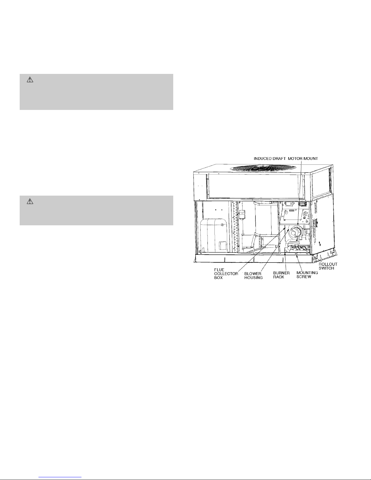
4. Check electrical connections for tightness and controls
for proper operation each heating and cooling season.
Service when necessary.
5. Check and inspect heating section before each heating
season. Clean and adjust when necessary.
6. Check flue hood and remove any obstructions if
necessary.
I. AIR FILTER
CAUTION:
Never operate the unit without a suitable air filter in the return-air duct system. Always replace the filter with the same dimensional size and type
as originally installed. See Tables 1 and 2 for recommended filter sizes.
Inspect air filter(s) at least once each month and replace
(throwaway-type) or clean (cleanable-type) at least twice during each heating and cooling season or whenever the filter(s)
becomes clogged with dust and lint.
II. EVAPORATOR BLOWER AND MOTOR
NOTE: All motors are prelubricated. Do not attempt to lu-
bricate these motors.
For longer life, operating economy, and continuing efficiency,
clean accumulated dirt and grease from the blower wheel and
motor annually.
WARNING:
Turn off the gas supply, then disconnect
and tag electrical power to the unit before cleaning and
lubricating the blower motor and wheel. Failure to adhere to this warning could cause personal injury or death.
To clean the blower motor and wheel:
1. Remove and disassemble blower assembly as follows:
a. Remove unit access panel.
b. Disconnect motor lead from blower relay (BR).
Disconnect yellow lead from terminal L2 of the
contactor.
c. On all units remove blower assembly from unit. Re-
move screws securing blower to blower partition and
slide assembly out. Be careful not to tear insulation
in blower compartment.
d. Ensure proper reassembly by marking blower wheel
and motor in relation to blower housing before
disassembly.
e. Loosen setscrew(s) that secures wheel to motor shaft,
remove screws that secure motor mount brackets to
housing, and slide motor and motor mount out of
housing.
2. Remove and clean blower wheel as follows:
a. Ensure proper reassembly by marking wheel
orientation.
b. Lift wheel from housing. When handling and/or clean-
ing blower wheel, be sure not to disturb balance weights
(clips) on blower wheel vanes.
c. Remove caked-on dirt from wheel and housing with
a brush. Remove lint and/or dirt accumulations from
wheel and housing with vacuum cleaner, using soft
brush attachment. Remove grease and oil with mild
solvent.
d. Reassemble wheel into housing.
e. Reassemble motor into housing. Be sure setscrews are
tightened on motor shaft flats and not on round part
of shaft.
f. Reinstall unit access panel.
3. Restore electrical power, then gas supply to unit. Start
unit and check for proper blower rotation and motor speeds
during heating and cooling cycles.
III. FLUE GAS PASSAGEWAYS
To inspect the flue collector box and upper areas of the heat
exchanger:
1. Remove the combustion blower wheel and motor assembly according to directions in Combustion-Air Blower section below.
2. Remove the 3 screws holding the blower housing to the
flue collector box cover (see Fig. 31).
3. Remove the 12 screws holding the flue collector box cover
(Fig. 31) to the heat exchanger assembly.Inspect the heat
exchangers.
4. Clean all surfaces as required using the wire brush.
IV. COMBUSTION-AIR BLOWER
Clean periodically to assure proper airflow and heating efficiency. Inspect blower wheel every fall and periodically during heating season. For the first heating season, inspect blower
wheel bimonthly to determine proper cleaning frequency.
To inspect blower wheel, remove draft hood assembly. Shine
a flashlight into opening to inspect wheel. If cleaning is required, remove motor and wheel as follows:
1. Remove unit access panel. (See Fig. 32.)
2. Remove the 7 screws that attach induced-draft motor
mounting plate to blower housing. (See Fig. 31.)
3. Slide the motor and blower wheel assembly out of the
blower housing. (See Fig. 33.) Clean the blower wheel.
If additional cleaning is required, continue with Steps 4
and 5.
4. To remove blower, remove 2 setscrews. (See Fig. 33.)
5. To remove motor and cooling fan assembly, remove
4 screws that hold blower housing to mounting plate.
6. To reinstall, reverse the procedure outlined above.
V. LIMIT SWITCH
Remove unit access panel. Limit switch is located on the blower
partition.
Fig. 31 — Blower Housing and Flue Collector Box
—30—
Page 31
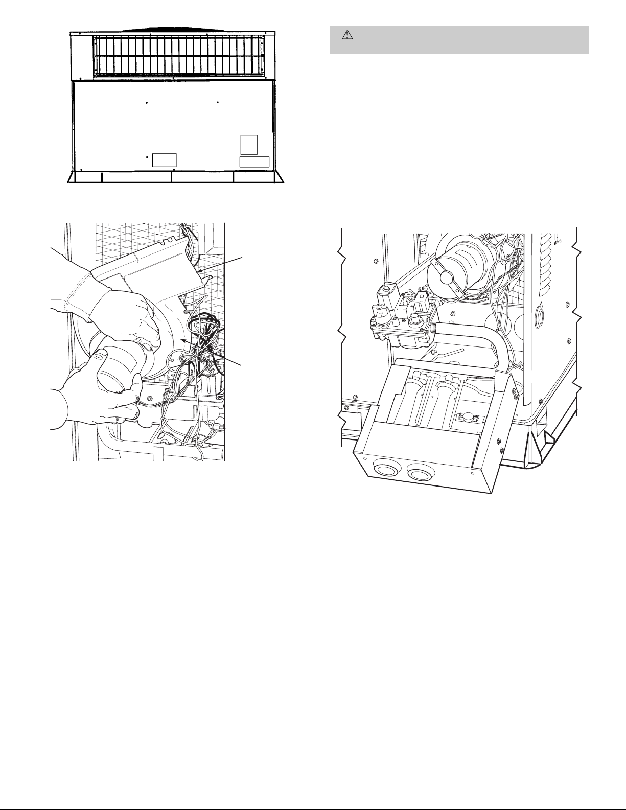
VI. BURNER IGNITION
Unit is equipped with a direct spark ignition 100% lockout
system. Ignition module is located in the control box. Module
contains a self-diagnostic LED. During servicing, refer to label diagram for LED interpretation.
If lockout occurs, unit may be reset by either momentarily
interrupting power supply to unit, or turning selector switch
to OFF position at the thermostat.
VII. MAIN BURNERS
At the beginning of each heating season, inspect for deterioration or blockage due to corrosion or other causes. Observe
the main burner flames and adjust if necessary.
CAUTION:
When servicing gas train, do not hit or
plug orifice spuds.
A. Removal of Gas Train
1. Shut off manual gas valve.
2. Shut off power to unit.
3. Remove unit access panel. (See Fig. 32.)
4. Disconnect gas piping at unit gas valve.
5. Remove wires connected to gas valve. Mark each wire.
6. Remove ignitor and sensor wires at the ignitor module.
7. Remove the mounting screw that attaches the burner
rack to the basepan. (See Fig. 31.)
8. Slide the burner rack out of the unit. (See Fig. 31
and 34.)
9. To reinstall, reverse the procedure outlined above.
VIII. CONDENSER COIL, EVAPORATOR COIL, AND
CONDENSATE DRAIN PAN
Inspect the condenser coil, evaporator coil, and condensate
drain pan at least once each year.
The coils are easily cleaned when dry; therefore, inspect and
clean the coils either before or after each cooling season.
Remove all obstructions, including weeds and shrubs, that
interfere with the airflow through the condenser coil.
Straighten bent fins with a fin comb. If coated with dirt or
lint, clean the coils with a vacuum cleaner,using the soft brush
Fig. 32 — Unit Access Panel
BLOWER
HOUSING
2 SETSCREWS
(HIDDEN)
Fig. 33 — Removal of Motor and Blower Wheel
Fig. 34 — Burner Rack Removed
—31—
Page 32
attachment. Be careful not to bend the fins. If coated with oil
or grease, clean the coils with a mild detergent-and-water solution. Rinse coils with clear water, using a garden hose. Be
careful not to splash water on motors, insulation, wiring, or
air filter(s). For best results, spray condenser coil fins from
inside to outside the unit. On units with an outer and inner
condenser coil, be sure to clean between the coils. Be sure to
flush all dirt and debris from the unit base.
Inspect the drain pan and condensate drain line when inspecting the coils. Clean the drain pan and condensate drain
by removing all foreign matter from the pan. Flush the pan
and drain tube with clear water. Do not splash water on the
insulation, motor, wiring, or air filter(s). If the drain tube is
restricted, clear it with a ‘‘plumbers snake’’ or similar probe
device. Ensure that the auxiliary drain port above the drain
tube is also clear.
IX. CONDENSER FAN
CAUTION:
Keep the condenser fan free from all obstructions to ensure proper cooling operation. Never place
articles on top of the unit. Damage to unit may result.
1. Remove 6 screws holding condenser grille and motor to
top cover.
2. Turn motor/grille assembly upside down on top cover to
expose the fan blade.
3. Inspect the fan blades for cracks or bends.
4. If fan needs to be removed, loosen the setscrew and slide
the fan off the motor shaft.
5. When replacing fan blade, position blade so that the hub
is
1
⁄8in. away from the motor end (1⁄8in. of motor shaft
will be visible).
6. Ensure that setscrew engages the flat area on the motor shaft when tightening.
7. Replace grille.
X. ELECTRICAL CONTROLS AND WIRING
Inspect and check the electrical controls and wiring annually. Be sure to turn off the gas supply, and then the electrical
power to the unit.
Remove access panel to locate all the electrical controls and
wiring. Check all electrical connections for tightness. Tighten
all screw connections. If any smoky or burned connections are
noticed, disassemble the connection, clean all the parts,
restrip the wire end and reassemble the connection properly
and securely.
After inspecting the electrical controls and wiring, replace the
access panel. Start the unit, and observe at least one complete heating cycle and one complete cooling cycle to ensure
proper operation. If discrepancies are observed in either or
both operating cycles, or if a suspected malfunction has occurred, check each electrical component with the proper electrical instrumentation. Refer to the unit wiring label when
making these checkouts.
NOTE: Refer to the heating and/or cooling sequence of operation in this publication as an aid in determining proper
control operation.
XI. REFRIGERANT CIRCUIT
Inspect all refrigerant tubing connections and the unit base
for oil accumulations annually. Detecting oil generally indicates a refrigerant leak.
If oil is detected or if low cooling performance is suspected,
leak-test all refrigerant tubing using an electronic leakdetector, halide torch, or liquid-soap solution. If a refrigerant
leak is detected, refer to Check for Refrigerant Leaks section
on page 15.
If no refrigerant leaks are found and low cooling performance is suspected, refer to Checking and Adjusting Refrigerant Charge section on page 22.
XII. GAS INPUT
The gas input does not require checking unless improper heating performance is suspected. If a problem exists, refer to
Start-Up section on page 15.
XIII. EVAPORATOR AIRFLOW
The heating and/or cooling airflow does not require checking
unless improper performance is suspected. If a problem ex-
ists, be sure that all supply- and return-air grilles are open
and free from obstructions, and that the air filter is clean. When
necessary, refer to Indoor Airflow and Airflow Adjustments
section on page 22 to check the system airflow.
XIV. METERING DEVICE — ACUTROL™ DEVICE
This metering device is a fixed orifice and is located in the
header to the evaporator coil.
XV. LIQUID LINE STRAINER
The liquid line strainer (to protect metering device) is made
of wire mesh and located in the liquid line on the inlet side of
the metering device.
—32—
Page 33
TROUBLESHOOTING
Cooling
SYMPTOM CAUSE REMEDY
Compressor and
condenser fan will
not start.
Power failure Call power company.
Fuse blown or circuit breaker tripped Replace fuse or reset circuit breaker.
Defective thermostat, contactor, transformer,
or control relay
Replace component.
Insufficient line voltage Determine cause and correct.
Incorrect or faulty wiring Check wiring diagram and rewire correctly.
Thermostat setting too high Lower thermostat setting below room temperature.
Compressor will not
start but condenser
fan runs.
Faulty wiring or loose connections in
compressor circuit
Check wiring and repair or replace.
Compressor motor burned out, seized, or
internal overload open
Determine cause. Replace compressor.
Defective run/start capacitor, overload,
start relay
Determine cause and replace.
One leg of 3-phase power dead Replace fuse or reset circuit breaker.
Determine cause.
Three-phase scroll
compressor
(582A048 and
583A030-060) makes
excessive noise,
and there may be
a low pressure
differential.
Scroll compressor is rotating in the
wrong direction
Correct the direction of rotation by reversing the
3-phase power leads to the unit. Shut down unit to
allow pressures to equalize.
Compressor cycles
(other than normally
satisfying
thermostat).
Refrigerant overcharge or undercharge Recover refrigerant, evacuate system, and
recharge to capacities shown on nameplate.
Defective compressor Replace and determine cause.
Insufficient line voltage Determine cause and correct.
Blocked condenser Determine cause and correct.
Defective run/start capacitor, overload
or start relay
Determine cause and replace.
Defective thermostat Replace thermostat.
Faulty condenser-fan motor or capacitor Replace.
Restriction in refrigerant system Locate restriction and remove.
Compressor
operates
continuously.
Dirty air filter Replace filter.
Unit undersized for load Decrease load or increase unit size.
Thermostat set too low Reset thermostat.
Low refrigerant charge Locate leak, repair, and recharge.
Leaking valves in compressor Replace compressor.
Air in system Recover refrigerant, evacuate system, and recharge.
Condenser coil dirty or restricted Clean coil or remove restriction.
Excessive head
pressure.
Dirty air filter Replace filter.
Dirty condenser coil Clean coil.
Refrigerant overcharged Recover excess refrigerant.
Air in system Recover refrigerant, evacuate system, and recharge.
Condenser air restricted or air short-cycling Determine cause and correct.
Head pressure too
low.
Low refrigerant charge Check for leaks, repair and recharge.
Compressor valves leaking Replace compressor.
Restriction in liquid tube Remove restriction.
Excessive suction
pressure.
High heat load Check for source and eliminate.
Compressor valves leaking Replace compressor.
Refrigerant overcharged Recover excess refrigerant.
Suction pressure
too low.
Dirty air filter Replace filter.
Low refrigerant charge Check for leaks, repair and recharge.
Metering device or low side restricted Remove source of restriction.
Insufficient evaporator airflow Increase air quantity. Check filter — replace if
necessary.
Temperature too low in conditioned area Reset thermostat.
Outdoor ambient below 40 F Install low-ambient kit.
Field-installed filter-drier restricted Replace.
—33—
Page 34
Heating
SYMPTOM CAUSE REMEDY
Burners will not ignite. Water in gas line Drain. Install drip leg.
No power to furnace Check power supply fuses, wiring, or circuit breaker.
No 24-v power supply to control
circuit
Check transformer.
NOTE: Some transformers have internal overcurrent
protection that requires a cool-down period to reset.
Miswired or loose connections Check all wiring and wirenut connections.
Burned-out heat anticipator in
thermostat
Replace thermostat.
Broken thermostat wire Run continuity check. Replace wire if necessary.
Misaligned spark electrodes Check flame ignition and sense electrode positioning.
Adjust as necessary.
No gas at main burners 1. Check gas line for air. Purge as necessary.
NOTE: After purging gas line of air, wait at least
5 minutes for any gas to dissipate before attempting to light unit.
2. Check gas valve.
Inadequate heating. Dirty air filter Clean or replace filter as necessary.
Gas input to furnace too low Check gas pressure at manifold. Match with that on
unit nameplate.
Unit undersized for application Replace with proper unit or add additional unit.
Restricted airflow Clean or replace filter. Remove any restriction.
Blower speed too low Use faster speed tap if available, or install alternate
motor.
Limit switch cycles main burners Check rotation of blower, thermostat heat antic-
ipator settings, temperature rise of unit. Adjust as
necessary.
Poor flame characteristics. Incomplete combustion results in:
Aldehyde odors, carbon monoxide, sooting flame, floating flame
1. Tighten all screws around burner compartment.
2. Cracked heat exchanger. Replace.
3. Unit overfired. Reduce input (change orifices or
adjust gas line or manifold pressure).
4. Check burner alignment.
—34—
Page 35
LED Troubleshooting — Error Code
SYMPTOM CAUSE REMEDY
Hardware failure.
(LED OFF)
Loss of power to control module
(IGC).
Check 5 amp fuse on IGC, power to unit, 24-v circuit
breaker, and transformer. Units without a 24-v circuit
breaker have an internal overload in the 24-v transformer. If the overload trips, allow 10 minutes for automatic reset.
Limit switch fault.
(LED 2 flashes)
High temperature limit switch is
open.
Check the operation of the indoor (evaporator) fan
motor. Ensure that the supply-air temperature rise is
in accordance with the range on the unit nameplate.
Flame sense fault.
(LED 3 flashes)
The IGC sensed flame that
should not be present.
Reset unit. If problem persists, replace control board.
4 consecutive limit switch
faults.
(LED 4 flashes)
Inadequate airflow to unit. Check operation of indoor (evaporator) fan motor and
that supply-air temperature rise agrees with range on
unit nameplate information.
Ignition lockout.
(LED 5 flashes)
Unit unsuccessfully attempted
ignition for 15 minutes.
Check ignitor and flame sensor electrode spacing,
gaps, etc. Ensure that flame sense and ignition wires
are properly terminated. Verify that unit is obtaining
proper amount of gas.
Induced-draft motor fault.
(LED 6 flashes)
IGC does not sense that induceddraft motor is operating.
Check for proper voltage. If motor is operating, check
the speed sensor plug/IGC Terminal J2 connection.
Proper connection: PIN 1 — White, PIN 2 — Red,
PIN 3 — Black.
Rollout switch fault.
(LED 7 flashes)
Rollout switch has opened. Rollout switch will automatically reset, but IGC will
continue to lockout unit. Check gas valve operation.
Ensure that induced-draft blower wheel is properly
secured to motor shaft. Reset unit at unit disconnect.
Internal control fault.
(LED 8 flashes)
Microprocessor has sensed an
error in the software or hardware.
If error code is not cleared by resetting unit power,
replace the IGC.
WARNING:
If the IGC must be replaced, be sure to ground
yourself to dissipate any electrical charge that may be present
before handling new control board. The IGC is sensitive to static
electricity and may be damaged if the necessary precautions are
not taken.
IMPORTANT: Refer to Heating troubleshooting chart for additional troubleshooting analysis.
LEGEND
IGC — Integrated Gas Unit Controller
LED — Light-Emitting Diode
—35—
Page 36

Page 37

Page 38
SERVICE TRAINING
Packaged Service Training programs are an excellent way to increase your knowledge of the equip-
ment discussed in this manual, including:
• Unit Familiarization
• Installation Overview
• Maintenance
• Operating Sequence
A large selection of product, theory, and skills programs are available, using popular video-based
formats and materials. All include video and/or slides, plus companion book.
Classroom Service Training which includes ‘‘hands-on’’ experience with the products in our labs can
mean increased confidence that really pays dividends in faster troubleshooting and fewer callbacks.
Course descriptions and schedules are in our catalog.
CALL FOR FREE CATALOG 1-800-962-9212
[ ] Packaged Service Training
[ ] Classroom Service Training
Copyright 1999 Bryant Heating & Cooling Systems CATALOG NO. 5358-203
Page 39

Page 40

START-UP CHECKLIST
(Remove and Store in Job File)
I. PRELIMINARY INFORMATION
MODEL NO.:
DATE:
SERIAL NO.:
TECHNICIAN:
II. PRE-START-UP (insert checkmark in box as each item is completed)
M VERIFY THAT ALL PACKING MATERIALS HAVE BEEN REMOVED FROM UNIT
M VERIFY THAT CONDENSATE CONNECTION IS INSTALLED PER INSTALLATION INSTRUCTIONS
M CHECK ALL ELECTRICAL CONNECTIONS AND TERMINALS FOR TIGHTNESS
M CHECK GAS PIPING FOR LEAKS
M CHECK THAT INDOOR (EVAPORATOR) AIR FILTER IS CLEAN AND IN PLACE
M VERIFY THAT UNIT INSTALLATION IS LEVEL
M CHECK FAN WHEEL AND PROPELLER FOR LOCATION IN HOUSING/ORIFICE AND SETSCREW
TIGHTNESS
III. START-UP
ELECTRICAL
SUPPLY VOLTAGE L1-L2
L2-L3 L3-L1
COMPRESSOR AMPS L1 L2 L3
COMPRESSOR AMPS L1 L2 L3
INDOOR (EVAPORATOR) FAN AMPS
TEMPERATURES
OUTDOOR (CONDENSER) AIR TEMPERATURE
DB
RETURN-AIR TEMPERATURE
DB WB
COOLING SUPPLY AIR
DB WB
GAS HEAT SUPPLY AIR
PRESSURES
GAS INLET PRESSURE
IN. WG
GAS MANIFOLD PRESSURE
IN. WG
REFRIGERANT SUCTION
PSIG SUCTION LINE TEMP*
REFRIGERANT DISCHARGE PSIG DISCHARGE TEMP†
M VERIFY REFRIGERANT CHARGE USING CHARGING TABLES
M VERIFY THAT 3-PHASE SCROLL COMPRESSOR ROTATING IN CORRECT DIRECTION (582A048 AND
583A030-060)
*Measured at suction inlet to compressor.
†Measured at liquid line leaving condenser.
----------------------------------------------------------------------------------------
CUT ALONG DOTTED LINE CUT ALONG DOTTED LINE
Copyright 1999 Bryant Heating & Cooling Systems CATALOG NO. 5358-203
 Loading...