

Page 1
Preferred Series
581J 04-06
Single Package Rooftop Gas Heat/Electric Cooling Unit with
®
Puron
(R-410A) Refrigerant
Installation Instructions
CONTENTS
Page
GENERAL . . . . . . . . . . . . . . . . . . . . . . . . . . . . . . . . . . . . . . . . . . 1
SAFETY CONSIDERATIONS . . . . . . . . . . . . . . . . . . . . . . . . . . 1
Rated Indoor Airflow (cfm). . . . . . . . . . . . . . . . . . . . . . . . . 2
Pre-Installation . . . . . . . . . . . . . . . . . . . . . . . . . . . . . . . . . . 2
INSTALLATION. . . . . . . . . . . . . . . . . . . . . . . . . . . . . . . . . . . . . 6
Jobsite Survey . . . . . . . . . . . . . . . . . . . . . . . . . . . . . . . . . . . 6
Step 1 — Plan for Unit Location. . . . . . . . . . . . . . . . . . . . .6
Step 2 — Plan for Sequence of Unit Installation . . . . . . . .7
Step 3 — Inspect Unit . . . . . . . . . . . . . . . . . . . . . . . . . . . . . 7
Step 4 — Provide Unit Support. . . . . . . . . . . . . . . . . . . . . . 7
Step 5 — Field Fabricate Ductwork . . . . . . . . . . . . . . . . . . 9
Step 6 — Rig and Place Unit. . . . . . . . . . . . . . . . . . . . . . . . 9
Step 7 — Convert to Horizontal and Connect
Ductwork. . . . . . . . . . . . . . . . . . . . . . . . . . . . . . . . . . .10
Step 8 — Install Outside Air Hood . . . . . . . . . . . . . . . . . . 11
Step 9 — Relocate Latch (Units with Hinged Panels
Only) . . . . . . . . . . . . . . . . . . . . . . . . . . . . . . . . . . . . . . 12
Step 10 — Install Flue Hood . . . . . . . . . . . . . . . . . . . . . . . 12
Step 11 — Install Gas Piping . . . . . . . . . . . . . . . . . . . . . .12
Step 12 — Install External Condensate Trap and Line . . . 14
Step 13 — Make Electrical Connections. . . . . . . . . . . . . . 15
Perfect Humidity™ System Control Connections. . . . . . . 19
EconoMi$er
Low Ambient Control (Factory Option) . . . . . . . . . . . . . .34
RTU Open Controller System . . . . . . . . . . . . . . . . . . . . . .36
Field Connections . . . . . . . . . . . . . . . . . . . . . . . . . . . . . . . 40
Communication Wiring — Protocols . . . . . . . . . . . . . . . . 43
Local Access . . . . . . . . . . . . . . . . . . . . . . . . . . . . . . . . . . . 44
Outdoor Air Enthalpy Control (P/N 33CSENTHSW) . . . 45
Smoke Detectors . . . . . . . . . . . . . . . . . . . . . . . . . . . . . . . . 46
Step 14 — Adjust Factory Installed Options. . . . . . . . . . . 47
Step 15 — Install Accessories. . . . . . . . . . . . . . . . . . . . . .47
Step 16 — Check Belt Tension . . . . . . . . . . . . . . . . . . . . .47
Pre-Start and Start-Up . . . . . . . . . . . . . . . . . . . . . . . . . . . . 48
START-UP CHECKLIST . . . . . . . . . . . . . . . . . . . . . . . . . . . CL-1
®
X (Factory-Installed Option) . . . . . . . . . . . 21
GENERAL
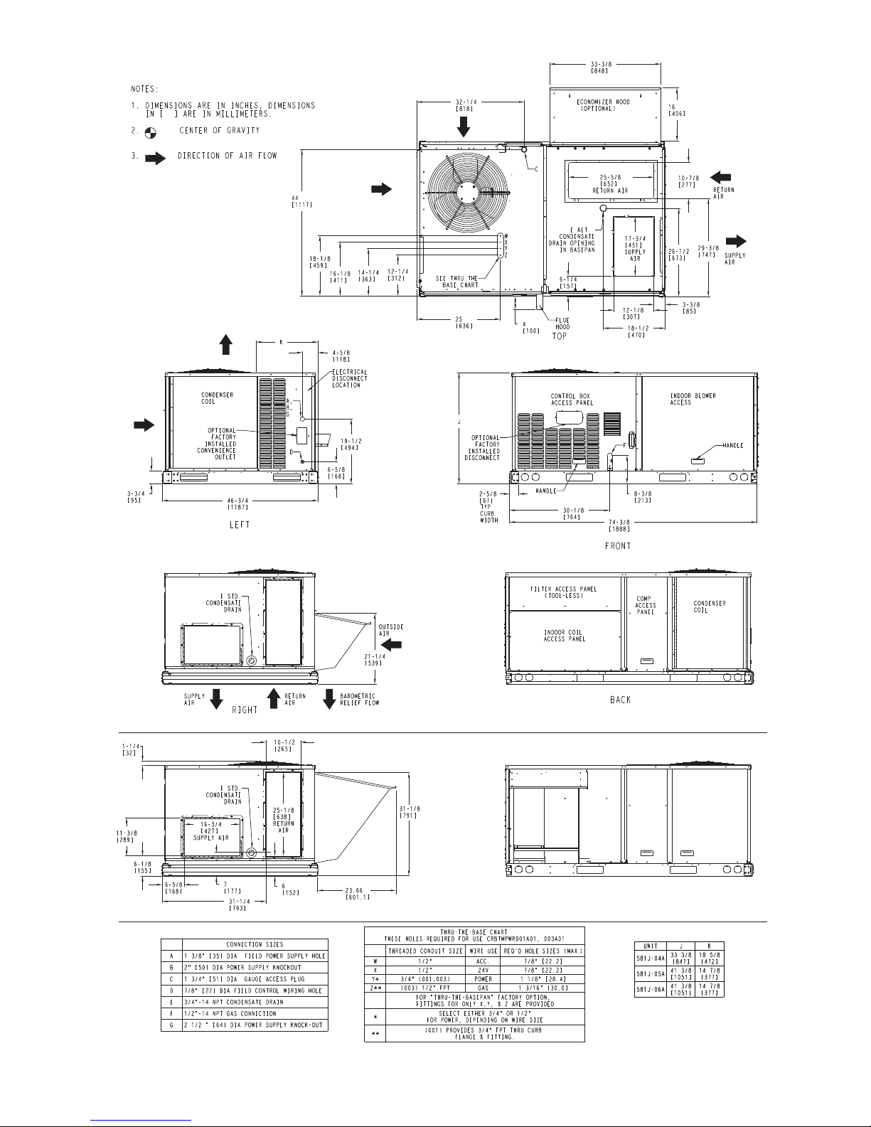
See Fig. 1 for 581J model number nomenclature. See Fig. 2
for unit dimensional drawings. Figure 3 shows service clearance dimensions.
SAFETY CONSIDERATIONS
Improper installation, adjustment, alteration, service, maintenance, or use can cause explosion, fire, electrical shock or
other conditions which may cause personal injury or property
damage. Consult a qualified installer, service agency, or your
distributor or branch for information or assistance. The
qualified installer or agency must use factory-authorized kits
or accessories when modifying this product. Refer to the individual instructions packaged with the kits or accessories when
installing.
Follow all safety codes. Wear safety glasses and work
gloves. Use quenching cloths for brazing operations and have
a fire extinguisher available. Read these instructions thoroughly and follow all warnings or cautions attached to the
unit. Consult local building codes and appropriate national
electrical codes (in USA, ANSI/NFPA70, National Electrical
Code (NEC); in Canada, CSA C22.1) for special requirements.
It is important to recognize safety information. This is the
safety-alert symbol
and in instructions or manuals, be alert to the potential for personal injury.
Understand the signal words DANGER, WARNING, CAUTION, and NOTE. These words are used with the safety-alert
symbol. DANGER identifies the most serious hazards which will
result in severe personal injury or death. WARNING signifies
hazards which could result in personal injury or death. CAUTION is used to identify unsafe practices, which may result in
minor personal injury or product and property damage. NOTE is
used to highlight suggestions which will result in enhanced installation, reliability, or operation.
. When you see this symbol on the unit
WARNING
CARBON-MONOXIDE POISONING HAZARD
Failure to follow instructions could result in severe personal injury or death due to carbon-monoxide poisoning, if
combustion products infiltrate into the building.
Check that all openings in the outside wall around the vent
(and air intake) pipe(s) are sealed to prevent infiltration of
combustion products into the building.
Check that furnace vent (and air intake) terminal(s) are not
obstructed in any way during all seasons.
WARNING
Electrical shock can cause personal injury and death. Shut
off all power to this equipment during installation and service. There may be more than one disconnect switch. Tag
all disconnect locations to alert others not to restore power
until work is completed.
Page 2
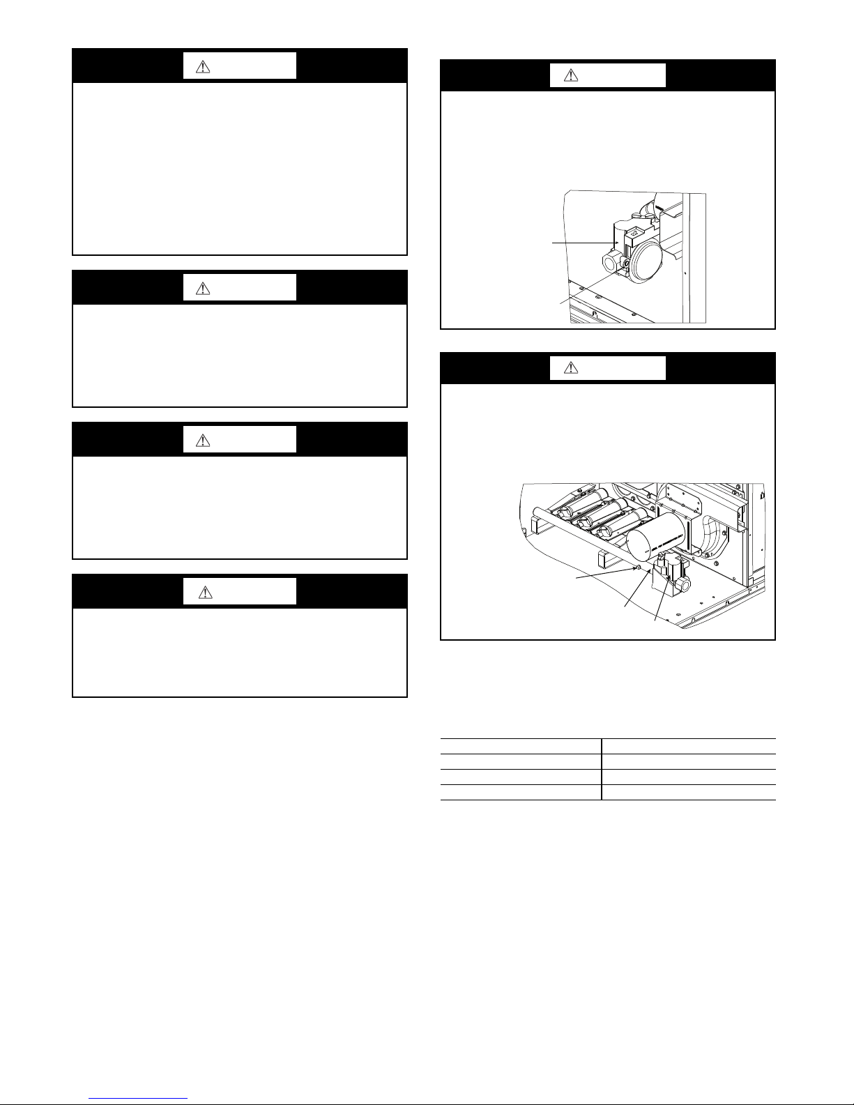
WARNING
MANIFOLD
GAS VALVE
MANIFOLD PRESSURE
TAP SET SCREW
Failure to follow this warning could result in personal
injury or death.
Disconnect gas piping from unit when leak testing at pressure greater than 0.5 psig (3450 Pa). Pressures greater than
0.5 psig (3450 Pa) will cause gas valve damage resulting in
hazardous condition. If gas valve is subjected to pressure
greater than 0.5 psig (3450 Pa), it must be replaced before
use. When pressure testing field-supplied gas piping at
pressures of 0.5 psig (3450 Pa) or less, a unit connected to
such piping must be isolated by closing the manual gas
valve.
WARNING
FIRE HAZARD
Failure to follow this warning could result in personal
injury, death, and/or property damage.
Inlet pressure tap set screw must be tightened and
pipe plug must be installed to prevent gas leaks.
GAS VALVE
1
/8 in. NPT
WARNING
Failure to follow this warning could cause personal injury,
death and/or equipment damage.
®
Puron
(R-410A) refrigerant systems operate at higher
pressures than standard R-22 systems. Do not use R-22 service equipment or components on Puron refrigerant equipment.
WARNING
Failure to follow this warning could cause personal injury
or death.
Relieve pressure and recover all refrigerant before system
repair or final unit disposal. Wear safety glasses and gloves
when handling refrigerants. Keep torches and other ignition sources away from refrigerants and oils.
CAUTION
Failure to follow this caution may result in personal injury.
Sheet metal parts may have sharp edges or burrs. Use care
and wear appropriate protective clothing, safety glasses and
gloves when handling parts and servicing air conditioning
equipment.
INLET PRESSURE
TAP SET SCREW
WARNING
FIRE HAZARD
Failure to follow this warning could result in personal
injury, death, and/or property damage.
Manifold pressure tap set screw must be tightened and
1
/8 in. NPT pipe plug must be installed to prevent gas leaks.
Rated Indoor Airflow (cfm) — Table 1 lists the rated
indoor airflow used for the AHRI efficiency rating for the
units covered in this document.
Table 1 — Rated Indoor Airflow
MODEL NUMBER FULL LOAD AIRFLOW (CFM)
581J*A/B/F04 1050
581J*A/B/F05 1400
581J*A/B/F06 1625
Pre-Installation — Complete the following checks before
installation.
1. Consult local building codes and the NEC (National
Electrical Code) ANSI/NFPA 70 for special installation requirements.
2. Determine unit location (from project plans) or select unit
location.
Check for possible overhead obstructions which may inter-
fere with unit lifting or rigging.
For model number nomenclature see Fig. 1. For unit dimen-
sions and service clearances see Fig. 2-4.
2
Page 3
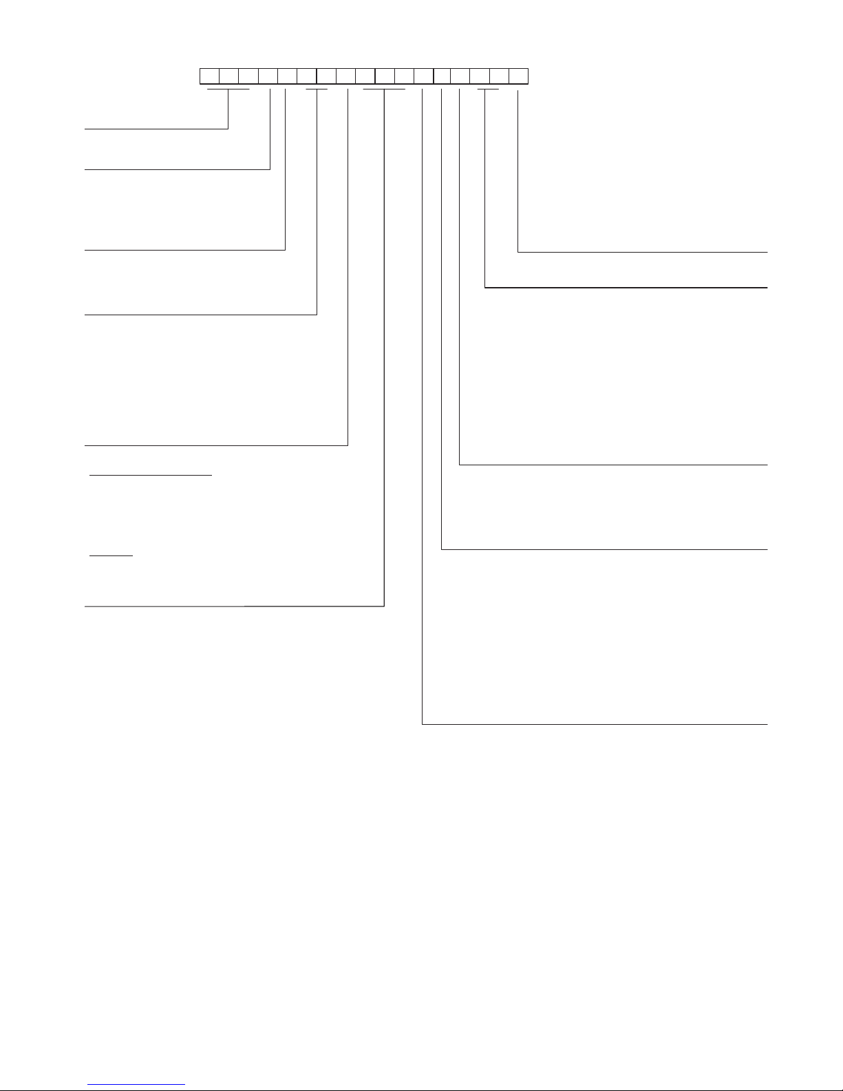
Unit Type
High Efficiency
Gas Heat RTU
Model
–
Puron Refrigerant Model
J
Voltage
E = 460-3-60
J = 208/230-1-60
P = 208/230-3-60
T = 575-3-60
1 2 3 4 5 6 7 8 9 1011121314151617
5 8 1 J E 0 6 A 0 7 2 A 0 B 0 A
A
Packaging and 2-Speed Indoor Fan
Motor
A = Standard Packaging, electro mech. controls
that require W7212 EconoMi$er IV
B = LTL Packaging, electro mech. controls that
require W7212 EconoMi$er IV
C = Standard Packaging, electro mech. controls
that require W7220 EconoMi$er X
D = Standard Packaging and 2-Speed Indoor Fan
Motor (VFD) Controller
E = LTL Packaging, and 2-Speed Indoor Fan
Motor (VFD) Controller
F = LTL Packaging, electro mech. controls that
require W7220 EconoMi$er X
Cooling Tons
04 - 3 ton
05 - 4 ton
06 - 5 ton
Refrig. System/Gas Heat Options
A = Standard One Stage cooling models/Nat. Gas Heat
B = Standard One Stage cooling models/Low NO
C = Standard One Stage cooling models/SS HX Heat
Heat
x
G = Standard One Stage cooling models and Perfect
Humidity™
H = Standard One Stage cooling/Low NOx Heat and
Perfect Humidity
J = Standard One Stage cooling/SS HX Heat and
Perfect Humidity
Heat Level Input
Standard/Stainless Steel
072 = 72,000 (1 Phase = 65,000) 180 = 180,000
115 = 115,000 (1 Phase = 90,000) 224 = 224,000
125 = 125,000 240 = 240,000
150 = 150,000 (1 Phase = 130,000) 250 = 250,000
Low NOx
060 = 60,000
090 = 90,000
120 = 120,000
Note: On single phase (-J voltage code) models, the
following are not available as a factory installed option:
- Perfect Humidity
- Coated Coils or Cu Fin Coils
- Louvered Hail Guards
- Economizer or 2 Position Damper
- Powered 115 Volt Convenience Outlet
Factory Installed Options
Outdoor Air Options
A = None
B = Temp Econo, Baro Relief, Standard Leak
(W7212 or W7220)
H = Enthalpy Econo, Baro Relief, Standard Leak
(W7212 or W7220)
E = Temp Econo, Baro Relief, Standard Leak w/CO
(W7212 or W7220)
L = Enthalpy Econo, Baro Relief, Standard Leak w/CO
(W7212 or W7220)
Q = Motorized 2 Position Damper
U = Temp Econo, Baro Relief, Ultra Low Leak, (W7220)
W = Enthalpy Econo, Baro Relief, Ultra Low Leak, (W7220)
Indoor Fan Options 3,4,5 Ton Models Only
0 = Electric (Direct) Drive x13 Motor
–
2 = Medium Static Option
3 = High Static Option
Belt Drive
–
Belt Drive
See price page details for specific Perfect Humidity
Coil Options (outdoor-indoor-hail guard)
A = Al/Cu - Al/Cu
B = Precoat Al/Cu - Al/Cu
C = E-coat Al/Cu - Al/Cu
D = E-coat Al/Cu - E-coat Al/Cu
E = Cu/Cu - Al/Cu
F = Cu/Cu - Cu/Cu
M = Al/Cu - Al/Cu – Louvered Hail Guards
N = Precoat Al/Cu - Al/Cu – Louvered Hail Guards
P = E-coat Al/Cu - Al/Cu – Louvered Hail Guards
Q = E-coat Al/Cu - E-coat Al/Cu – Louvered Hail Guards
R = Cu/Cu - Al/Cu – Louvered Hail Guards
S = Cu/Cu - Cu/Cu – Louvered Hail Guards
2
2
Fig. 1 — 581J 04-06 Model Number Nomenclature (Example)
3
Page 4
Vertical Connections / Economizer
Horizontal Connections / Economizer
Fig. 2 — Unit Dimensional Drawing
4
Page 5
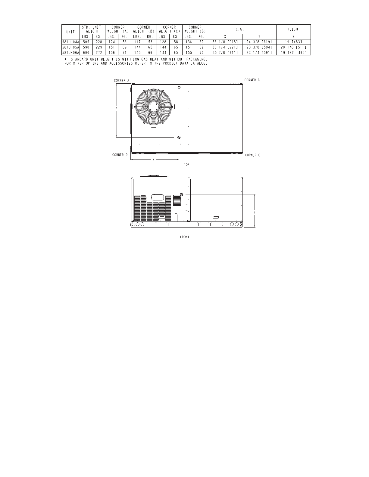
Fig. 2 — Unit Dimensional Drawing (cont)
5
Page 6
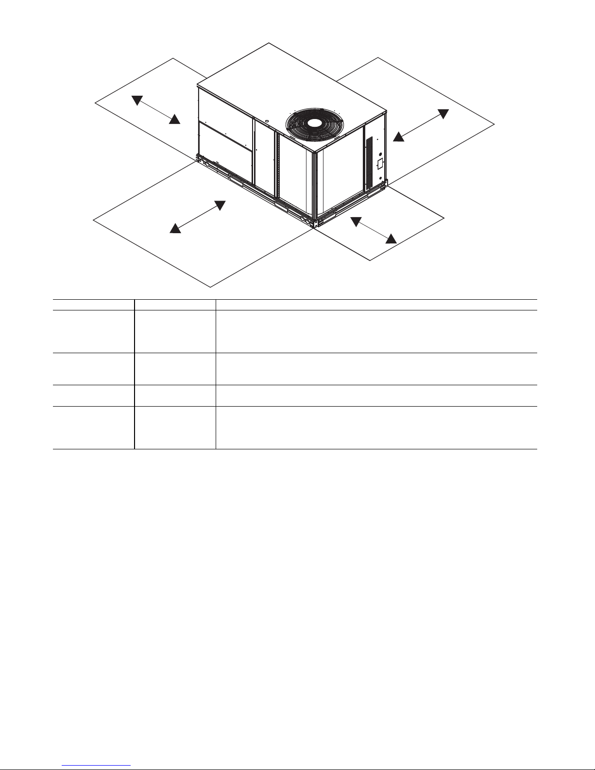
Fig. 3 — Service Clearance Dimensional Drawing
C
B
A
D
LOCATION DIMENSION CONDITION
A
48 in. (1219 mm) Unit disconnect is mounted on panel
18 in. (457 mm) No disconnect, convenience outlet option
18 in. (457 mm) Recommended service clearance
12 in. (305 mm) Minimum clearance
B
40 in. (1067 mm) Surface behind servicer is grounded (e.g., metal, masonry wall)
36 in. (914 mm) Surface behind servicer is electrically non-conductive (e.g., wood, fiberglass)
Special Check sources of flue products within 10 ft (3 m) of unit fresh air intake hood
C
36 in. (914 mm) Side condensate drain is used
18 in. (457 mm) Minimum clearance
D
48 in. (1219 mm) No flue discharge accessory installed, surface is combustible material
42 in. (1067 mm) Surface behind servicer is grounded (e.g., metal, masonry wall)
36 in. (914 mm) Surface behind servicer is electrically non-conductive (e.g., wood, fiberglass)
Special Check for adjacent units or building fresh air intakes within 10 ft (3 m) of this unit’s flue outlet
INSTALLATION
Jobsite Survey —
installation.
1. Consult local building codes and the NEC (National
Electrical Code) ANSI/NFPA 70 for special installation
requirements.
2. Determine unit location (from project plans) or select
unit location.
3. Check for possible overhead obstructions which may
interfere with unit lifting or rigging.
Complete the following checks before
Step 1 — Plan for Unit Location — Select a location
for the unit and its support system (curb or other) that provides for the minimum clearances required for safety. This
includes the clearance to combustible surfaces, unit performance and service access below, around and above unit as
specified in unit drawings. See Fig. 3.
NOTE: Consider also the effect of adjacent units.
block the combustion intake or flue outlet.
Class A, B, or C roof-covering material when roof curb is
used.
Be sure that unit is installed such that snow will not
Unit may be installed directly on wood flooring or on
6
Do not install unit in an indoor location. Do not locate air
inlets near exhaust vents or other sources of contaminated
air. For proper unit operation, adequate combustion and
ventilation air must be provided in accordance with Section
5.3 (Air for Combustion and Ventilation) of the National
Fuel Gas Code, ANSI Z223.1 (American National Standards Institute) and NFPA (National Fire Protection Association) 54 TIA–54–84–1. In Canada, installation must be in
accordance with the CAN1–B149 installation codes for gas
burning appliances.
Although unit is weatherproof, avoid locations that permit water from higher level runoff and overhangs to fall
onto the unit.
Locate mechanical draft system flue assembly at least
4 ft (1.2 m) from any opening through which combustion
products could enter the building, and at least 4 ft (1.2 m)
from any adjacent building (or per local code). Locate the
flue assembly at least 10 ft (3.05 m) from an adjacent unit’s
fresh air intake hood if within 3 ft (0.91 m) of same elevation (or per local code). When unit is located adjacent to
public walkways, flue assembly must be at least 7 ft (2.1 m)
above grade.
Select a unit mounting system that provides adequate
height to allow installation of condensate trap per
Page 7
requirements. Refer to Step 12 — Install External Condensate
Trap and Line on page 14 for required trap dimensions.
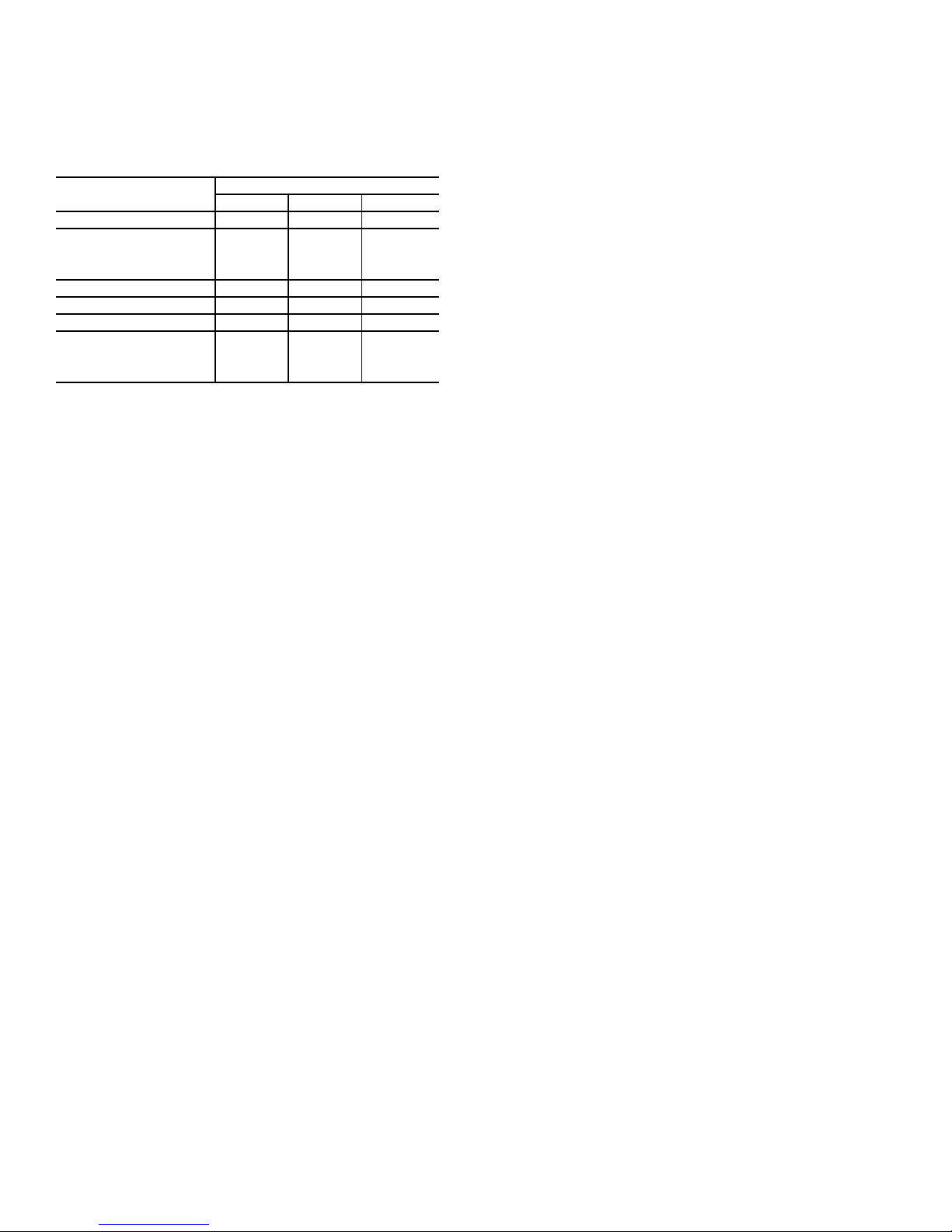
ROOF MOUNT — Check building codes for weight distribution requirements. Unit operating weights are shown in
Table 2.
Table 2 — Operating Weights
581J--
Base Unit 505 (229) 590 (268) 600 (272)
Economizer
Vertical 50 (23) 50 (23) 50 (23)
Horizontal 80 (36) 80 (36) 80 (36)
Perfect Humidity
Cu Fins 25 (11) 43 (20) 56 (25)
Powered Outlet 32 (15) 32 (15) 32 (15)
Curb
14 in. (356 mm) 110 (50) 110 (50) 110 (50)
24 in. (610 mm) 145 (66) 145 (66) 145 (66)
™
System 27 (10) 34 (13) 34 (13)
UNIT LB (KG)
04 05 06
Step 2 — Plan for Sequence of Unit Installation —
The support method used for this unit will dictate different
sequences for the steps of unit installation. For example, on
curb-mounted units, some accessories must be installed on the
unit before the unit is placed on the curb. Review the following
for recommended sequences for installation steps:
CURB-MOUNTED INSTALLATION
1. Install curb
2. Install field-fabricated ductwork inside curb
3. Install accessory thru-base service connection package
(affects curb and unit) (refer to accessory installation
instructions for details)
4. Prepare bottom condensate drain connection to suit
planned condensate line routing (refer to Step 12 —
Install External Condensate Trap and Line on page 14 for
details)
5. Rig and place unit
6. Install outdoor air hood
7. Install flue hood
8. Install gas piping
9. Install condensate line trap and piping
10. Make electrical connections
11. Install other accessories
PAD-MOUNTED INSTALLATION
1. Prepare pad and unit supports
2. Check and tighten the bottom condensate drain connection plug
3. Rig and place unit
4. Convert unit to side duct connection arrangement
5. Install field-fabricated ductwork at unit duct openings
6. Install outdoor air hood
7. Install flue hood
8. Install gas piping
9. Install condensate line trap and piping
10. Make electrical connections
11. Install other accessories
FRAME-MOUNTED INSTALLATION — Frame-mounted applications generally follow the sequence for a curb installation. Adapt the sequence as required to suit specific installation plan.
Step 3 — Inspect Unit — Inspect unit for transportation
damage. File any claim with transportation agency.
Confirm before installation of unit that voltage, amperage
and circuit protection requirements listed on unit data plate
agree with power supply provided.
On units with hinged panel option, check to be sure all
latches are snug and in closed position.
Locate the carton containing the outside air hood parts. Do
not remove carton until unit has been rigged and located in final position.
Step 4 — Provide Unit Support
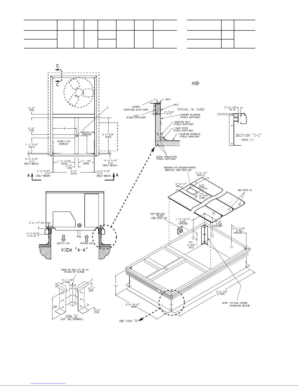
ROOF CURB MOUNT — Accessory roof curb details and
dimensions are shown in Fig. 4. Assemble and install accessory roof curb in accordance with instructions shipped with
the curb.
NOTE: The gasketing of the unit to the roof curb is critical for a
watertight seal. Install gasket supplied with the roof curb as
shown in Fig. 4. Improperly applied gasket can also result in air
leaks and poor unit performance.
Curb should be level. This is necessary for unit drain to
function properly. Unit leveling tolerances are shown in
Fig. 5. Refer to Accessory Roof Curb Installation Instructions
for additional information as required.
7
Page 8
CONNECTOR
PKG. ACCY.
BC
D ALT
DRAIN
HOLE
GAS POWER CONTROL
ACCESSORY
POWER
CRBTMPWR001A01
1’-9
11
/16”
[551]
1
3
/4”
[44.5]
1’-4”
[406]
3
/4” [19]
NPT
CRBTMPWR003A01
3
/4” [19]
NPT
1
/2” [12.7]
NPT
1
/2” [12.7]
NPT
1
/2” [12.7]
NPT
ROOFCURB
ACCESSORY
AUNIT SIZE
CRRFCURB002A01
CRRFCURB001A01
1’-2”
[356]
2’-0”
[610]
581J*04-06
NOTES:
1. Roof curb accessory is shipped disassembled.
2. Insulated panels.
3. Dimensions in [ ] are in millimeters.
4. Roof curb: galvanized steel.
5. Attach ductwork to curb (flanges of duct rest on curb).
6. Service clearance: 4 ft on each side.
7. Direction of airflow.
8. Connector package CRBTMPWR001A01 is for
thru-the-curb type gas
.
CRBTMPWR003A01 is for thru-the-base type
gas connections.
Fig. 4 — Roof Curb Details
8
Page 9
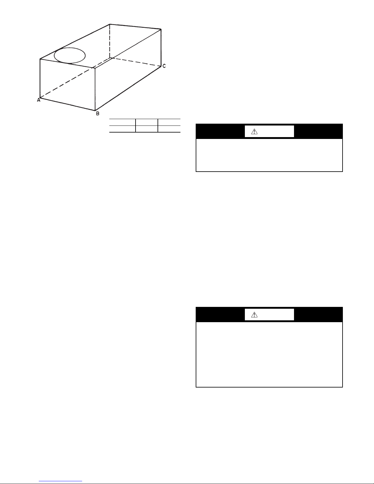
Fabricate supply ductwork so that the cross sectional di-
MAXIMUM ALLOWABLE
DIFFERENCE IN. (MM)
A-B B-C A-C
0.5 (13) 1.0 (25) 1.0 (25)
mensions are equal to or greater than the unit supply duct
opening dimensions for the first 18 in. (458 mm) of duct
length from the unit basepan.
Insulate and weatherproof all external ductwork, joints,
and roof openings with counter flashing and mastic in accordance with applicable codes.
Ducts passing through unconditioned spaces must be insulated and covered with a vapor barrier.
If a plenum return is used on a vertical unit, the return
should be ducted through the roof deck to comply with applicable fire codes.
A minimum clearance is not required around ductwork.
Step 6 — Rig and Place Unit
CAUTION
Fig. 5 — Unit Leveling Tolerances
Install insulation, cant strips, roofing felt, and counter
flashing as shown. Ductwork must be attached to curb and
not to the unit. The accessory thru-the-base power and gas
connection package must be installed before the unit is set
on the roof curb. If field-installed thru-the-roof curb gas
connections are desired, use factory-supplied
1
/2-in. pipe
coupling and gas plate assembly to mount the thru-the-roof
curb connection to the roof curb. Gas connections and power connections to the unit must be field-installed after the
unit is installed on the roof curb.
If electric and control wiring is to be routed through the
basepan, attach the accessory thru-the-base service connections to the basepan in accordance with the accessory installation instructions.
SLAB MOUNT (HORIZONTAL UNITS ONLY) —
Provide a level concrete slab that extends a minimum of 6 in.
(150 mm) beyond unit cabinet. Install a gravel apron in front of
condenser coil air inlet to prevent grass and foliage from
obstructing airflow.
NOTE: Horizontal units may be installed on a roof curb if
required.
ALTERNATE UNIT SUPPORT (IN LIEU OF CURB
OR SLAB MOUNT) — A non-combustible sleeper rail
can be used in the unit curb support area. If sleeper rails
cannot be used, support the long sides of the unit with a
minimum of 3 equally spaced 4-in. x 4-in. (102 mm x
102 mm) pads on each side.
Step 5 — Field Fabricate Ductwork — Cabinet re-
turn-air static pressure (a negative condition) shall not exceed 0.35 in. wg (87 Pa) with economizer or 0.45 in. wg
(112 Pa) without economizer.
For vertical ducted applications, secure all ducts to roof
curb and building structure. Do not connect ductwork to
unit.
Failure to follow this caution may result in damage to roofing materials.
Membrane roofs can be cut by sharp sheet metal edges. Be
careful when placing any sheet metal parts on such roof.
Keep unit upright and do not drop. Spreader bars are required. Rollers may be used to move unit across a roof. Rigging materials under unit (cardboard or wood) must be removed PRIOR to placing the unit on the roof curb. Level by
using unit frame as a reference. See Table 2 and Fig. 6 for
additional information.
Lifting holes are provided in base rails as shown in
Fig. 6. Refer to rigging instructions on unit.
Rigging materials under unit (cardboard to prevent base
pan damage) must be removed PRIOR to placing the unit on
the roof curb
When using the standard side drain connection, ensure
the red plug in the alternate bottom connection is tight. Do
this before setting the unit in place. The red drain plug an be
tightened with a
1
/2-in. square socket drive extension. For
further details, see “Step 12 — Install External Condensate
Trap and Line” on page 14.
Before setting the unit onto the curb, recheck gasketing
on curb.
CAUTION
Failure to follow this caution may result in injury or equipment damage.
All panels must be in place when rigging. Unit is not
designed for handling by fork truck when panels or packaging are removed.
If using top crate as spreader bar, once unit is set, carefully
lower wooden crate off building roof top to ground. Ensure
that no people or obstructions are below prior to lowering
the crate.
9
Page 10
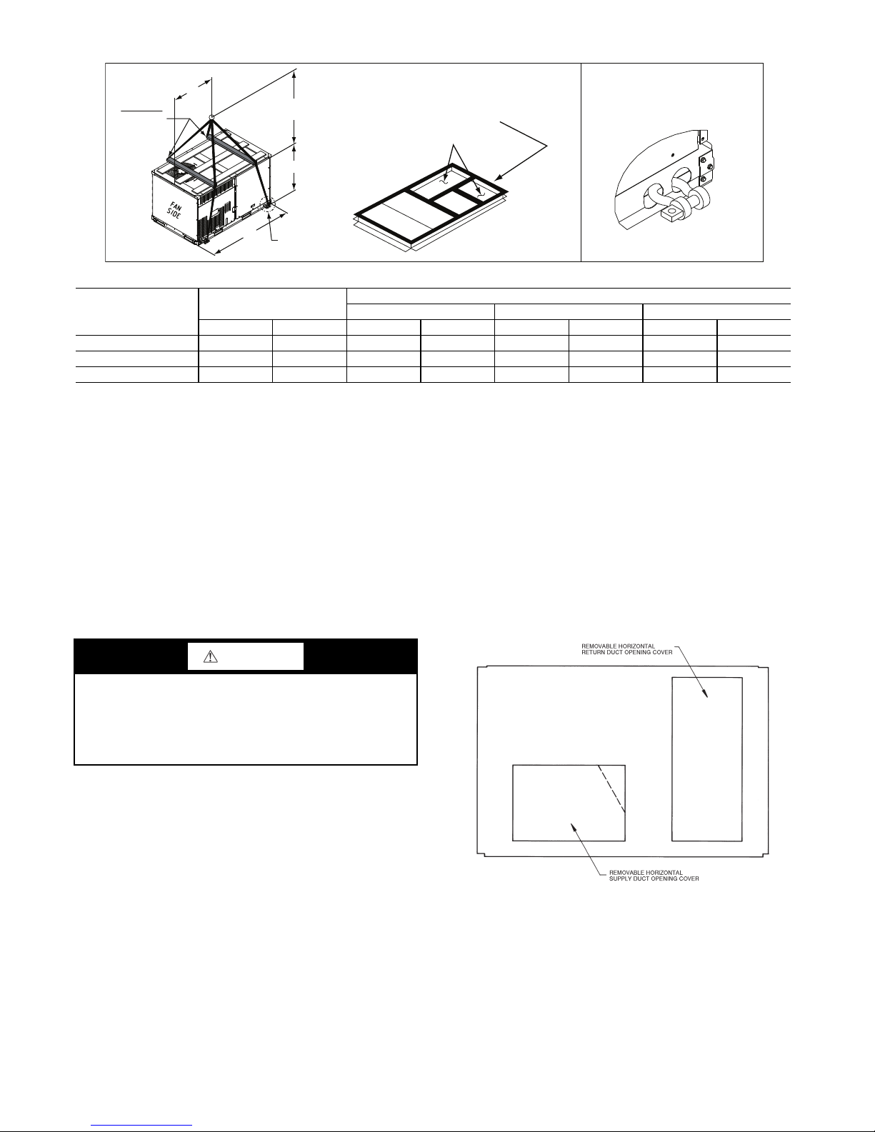
Fig. 6 — Rigging Details
DETAIL "A"
PLACE ALL SEAL STRIP IN PLACE
BEFORE PLACING UNIT ON ROOF CURB.
DUCT END
SEE DETAIL "A"
"A"
(914-1371)
36"- 54"
"C"
"B"
SPREADER
BARS
REQUIRED
NOTES:
1. SPREADER BARS ARE REQUIRED. Top damage will occur if spreader bars are not used.
2. Dimensions in () are in millimeters.
3. Hook rigging shackles through holes in base rail, as shown in Detail A. Holes in base rails are centered around the unit center of gravity. Use wooden
top to prevent rigging straps from damaging unit.
MAX WEIGHT
DIMENSIONS
UNIT ABC
LB KG in. MM in. MM in. MM
581J-04A 760 345 74.5 1890 38.0 965 33.5 850
581J-05A 895 407 74.5 1890 38.0 965 41.5 1055
581J-06A 930 423 74.5 1890 37.5 955 41.5 1055
POSITIONING ON CURB — Position unit on roof curb
so that the following clearances are maintained:
1
/4 in. (6.4
mm) clearance between the roof curb and the base rail inside the front and rear, 0.0 in. clearance between the roof
curb and the base rail inside on the duct end of the unit. This
will result in the distance between the roof curb and the base
rail inside on the condenser end of the unit being approxi-
1
mately
/4 in. (6.4 mm).
Although unit is weatherproof, guard against water from
higher level runoff and overhangs.
Step 7 — Convert to Horizontal and Connect
Ductwork (When Required) — Unit is shipped in the
vertical duct configuration. Unit without factory-installed
economizer or return air smoke detector option may be
field-converted to horizontal ducted configuration. To convert to horizontal configuration, remove screws from side
duct opening covers and remove covers. Using the same
screws, install covers on vertical duct openings with the insulation-side down. Seals around duct openings must be
tight. See Fig. 7.
CAUTION
Failure to follow this caution may result in equipment damage.
All panels must be in place when rigging. Unit is not
designed for handling by fork truck when panels or packaging are removed.
Flue vent discharge must have a minimum horizontal
clearance of 4 ft (1220 mm) from electric and gas meters,
gas regulators, and gas relief equipment. Minimum distance
between unit and other electrically live parts is 48 inches
(1220 mm).
Flue gas can deteriorate building materials. Orient unit
such that flue gas will not affect building materials. Locate
mechanical draft system flue assembly at least 48 in.
(1220 mm) from an adjacent building or combustible
material.
NOTE: Installation of accessory flue discharge deflector kit
will reduce the minimum clearance to combustible material to
18 in. (460 mm).
After unit is in position, remove rigging skids and shipping materials.
duct openings and all ductwork should be secured to the
flanges. Insulate and weatherproof all external ductwork,
joints, and roof or building openings with counter flashing
and mastic in accordance with applicable codes.
tive data plate when insulating horizontal ductwork.
10
Fig. 7 — Horizontal Conversion Panels
Field-supplied flanges should be attached to horizontal
Do not cover or obscure visibility to the unit’s informa-
Page 11
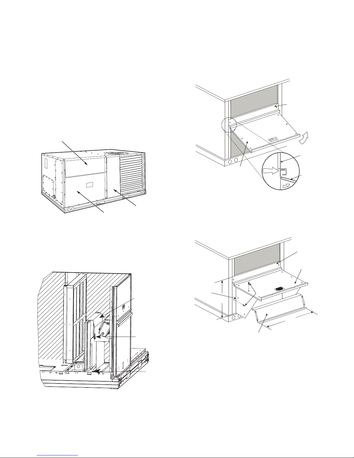
Step 8 — Install Outside Air Hood
FILTER ACCESS PANEL
OUTDOOR-AIR OPENING AND
INDOOR COIL ACCESS PANEL
COMPRESSOR
ACCESS PANEL
Hood Parts
Plastic Tie Wrap
Qty (2)
Screws for
Metal Tray
Qty (2)
TOP
PAN EL
INDOOR
COIL
ACCESS
PAN EL
INDOOR
COIL
ACCESS
PAN EL
CAULK
HERE
TOP
PAN EL
ECONOMIZER AND TWO POSITION DAMPER
HOOD PACKAGE REMOVAL AND SETUP (FACTORY OPTION)
NOTE: Economizer and two position damper are not available
as factory installed options for single phase (-3 voltage code)
models.
The hood is shipped in knock-down form and must be
field assembled. The indoor coil access panel is used as the
hood top while the hood sides, divider and filter are packaged together, attached to a metal support tray using plastic
stretch wrap, and shipped in the return air compartment behind the indoor coil access panel. The hood assembly’s metal tray is attached to the basepan and also attached to the
damper using two plastic tie-wraps.
1. To gain access to the hood, remove the filter access
panel. See Fig. 8.
ECONOMIZER AND TWO-POSITION HOOD
NOTE: If the power exhaust accessory is to be installed on the
unit, the hood shipped with the unit will not be used and must
be discarded. Save the aluminum filter for use in the power exhaust hood assembly.
1. The indoor coil access panel will be used as the top of
the hood. Remove the screws along the sides and bottom of the indoor coil access panel. See Fig. 10.
2. Locate the (2) screws holding the metal tray to the
Fig. 8 — Typical Access Panel Locations
basepan and remove. Locate and cut the (2) plastic tiewraps securing the assembly to the damper. See Fig. 9.
Be careful to not damage any wiring or cut tie-wraps
securing any wiring.
Fig. 9 — Economizer and Two-Position Damper Hood
3. Carefully lift the hood assembly (with metal tray)
Parts Location
through the filter access opening and assemble per the
steps outlined in the Economizer Hood and Two-Position Hood section.
Fig. 10 — Indoor Coil Access Panel Relocation
2. Swing out indoor coil access panel and insert the hood
sides under the panel (hood top). Use the screws provided to attach the hood sides to the hood top. Use
screws provided to attach the hood sides to the unit. See
Fig. 11.
TOP
PAN EL
INDOOR COIL
ACCESS PANEL
LEFT
HOOD
SIDE
19 1/16”
B
(483mm)
HOOD DIVIDER
SCREW
33 3/8”
(848mm)
Fig. 11 — Economizer Hood Construction
3. Remove the shipping tape holding the economizer
barometric relief damper in place (economizer only).
4. Insert the hood divider between the hood sides. See
Fig. 11 and 12. Secure hood divider with 2 screws on
each hood side. The hood divider is also used as the
bottom filter rack for the aluminum filter.
5. Open the filter clips which are located underneath the
hood top. Insert the aluminum filter into the bottom filter rack (hood divider). Push the filter into position past
the open filter clips. Close the filter clips to lock the filter into place. See Fig. 12.
6. Caulk the ends of the joint between the unit top panel
and the hood top.
7. Replace the filter access panel.
11
Page 12
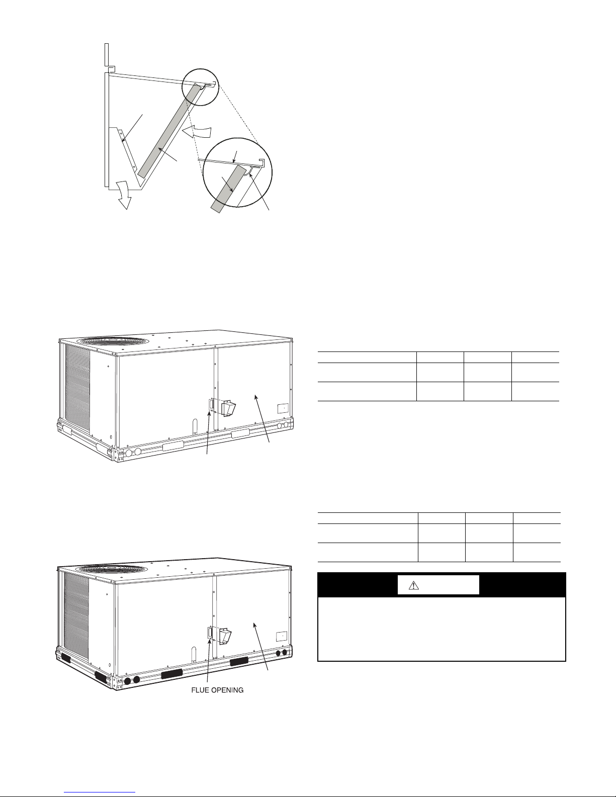
Fig. 12 — Economizer Filter Installation
DIVIDER
BAROMETRIC
RELIEF
CLEANABLE
ALUMINUM
FILTER
FILTER
HOOD
FILTER
CLIP
OUTSIDE
AIR
BLOWER
ACCESS
PANEL
FLUE OPENING
BLOWER
ACCESS
PANEL
Step 9 — Relocate Latch (Units with Hinged Panels
Only) —
compartment behind the hinged compressor door to location
shown in Fig. 13 after unit installation.
If the unit does not have hinged panels, skip this step and
continue at Step 10 below.
Relocate latch shipped inside the compressor
Step 11 — Install Gas Piping — Installation of the gas
piping must be accordance with local building codes and
with applicable national codes. In U.S.A., refer to NFPA 54/
ANSI Z223.1 National Fuel Gas Code (NFGC). In Canada,
installation must be accordance with the CAN/CSA B149.1
and CAN/CSA B149.2 installation codes for gas burning
appliances.
This unit is factory equipped for use with Natural Gas
fuel at elevations up to 2000 ft (610 m) above sea level. Unit
may be field converted for operation at elevations above
2000 ft (610 m) and/or for use with liquefied petroleum fuel. See accessory kit installation instructions regarding these
accessories.
NOTE: Furnace gas input rate on rating plate is for installation
up to 2000 ft (610 m) above sea level. In U.S.A. the input rating for altitudes above 2000 ft (610 m) must be derated by 4%
for each 1000 ft (305 m) above sea level. In Canada the input
rating must be derated by 10% for altitudes of 2000 ft (610 m)
to 4500 ft (1372 m) above sea level.
For natural gas applications, gas pressure at unit gas connection must not be less than 4 in. wg (996 Pa) or greater
than 13 in. wg (3240 Pa) while the unit is operating. On
581J*05-06 high-heat units, the gas pressure at unit gas connection must not be less than 5 in. wg (1245 Pa) or greater
than 13 in. wg (3240 Pa) while the unit is operating. See Table 3. For liquefied petroleum applications, the gas pressure
must not be less than 11 in. wg (2740 Pa) or greater than
13.6 in. wg (3390 Pa) at the unit connection.
Table 3 — Natural Gas Supply Line Pressure Ranges
Fig. 13 — Compressor Door Latch Location
Step 10 — Install Flue Hood — Flue hood is shipped
screwed to the basepan beside the burner compartment access panel. Remove from shipping location and using
screws provided, install flue hood and screen in location
shown in Fig. 14.
UNIT MODEL UNIT SIZE MIN. MAX.
581JD/E/L/M/S/R 04, 05, 06
581JF/N/T
(High Heat Units Only)
04, 05, 06
4.0 in. wg
(996 Pa)
5.0 in. wg
(1245 Pa)
13.0 in. wg
(3240 Pa)
13.0 in. wg
(3240 Pa)
The gas supply pipe enters the unit at the burner access
panel on the front side of the unit, through the long slot at
the bottom of the access panel. The gas connection to the
unit is made to the
1
/2-in. FPT gas inlet port on the unit gas
valve.
Manifold pressure is factory-adjusted for natural gas fuel
use. Adjust as required to obtain best flame characteristics.
See Table 4.
Table 4 — Natural Gas Manifold Pressure Ranges
UNIT MODEL UNIT SIZE HIGH FIRE LOW FIRE
581JD/E/L/M/S/R 04, 05, 06
581JF/N/T
(High Heat Units Only)
04, 05, 06
3.5 in. wg
(872 Pa)
3.5 in. wg
(872 Pa)
1.7 in. wg
(423 Pa)
1.7 in. wg
(423 Pa)
CAUTION
Failure to follow this caution may result in equipment damage.
When connecting the gas line to the unit gas valve, the
installer MUST use a backup wrench to prevent damage to
the valve.
Fig. 14 — Flue Hood Details
Install a gas supply line that runs to the unit heating section. Refer to the NFPA 54/NFGC or equivalent code for
gas pipe sizing data. Do not use a pipe size smaller than
1
/2-in. Size the gas supply line to allow for a maximum pressure drop of 0.5-in. wg (124 Pa) between gas regulator
source and unit gas valve connection when unit is operating
at high-fire flow rate.
12
Page 13
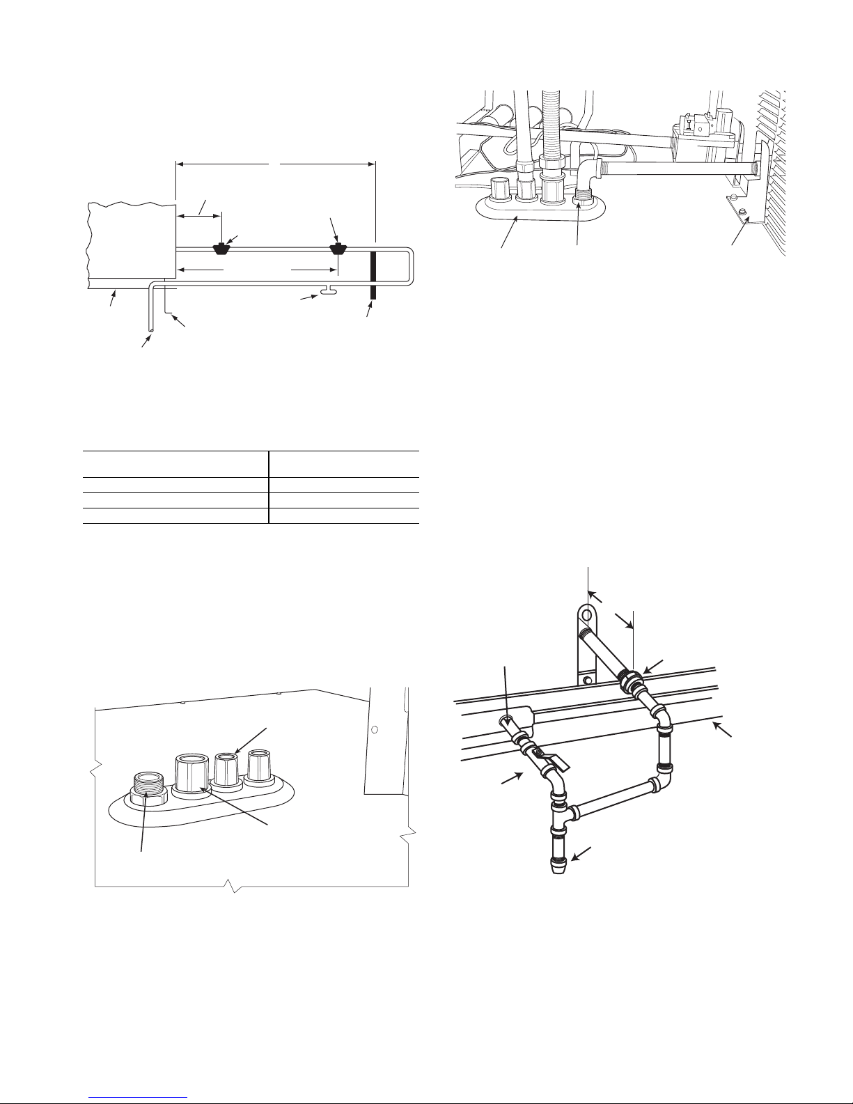
The gas supply line can approach the unit in three ways:
X
BASE UNIT
BASE RAIL
ROOF
CURB
9” MINIMUM CLEARANCE
FOR PANEL REMOVAL
MANUAL GAS
SHUTOFF VALVE
*
GAS
REGULATOR
*
48” MINIMUM
DRIP LEG
PER NFGC
*
FIELD-FABRICATED
SUPPORT
*
FROM
GAS
METER
LEGEND *Field supplied.
NOTE: Follow all local codes.
NFGC —
National Fuel Gas
Code
STEEL PIPE NOMINAL
DIAMETERS (IN.)
SPACING OF SUPPORTS
X DIMENSION (FT.)
1
/
2
6
3
/4 or 1 8
1-
1
/4 or larger 10
9” (229mm) min
Union
Shut Off
Valve
Drip
Leg
Thru-Curb Adapter
Unit Base Rail
horizontally from outside the unit (across the roof), thrucurb/under unit basepan (accessory kit required), or through
unit basepan (factory option or accessory kit required). Consult accessory kit installation instructions for details on
these installation methods. Observe clearance to gas line
components per Fig. 15.
tend it through the access panel at the gas support bracket.
See Fig. 17.
Fig. 15 — Gas Piping Guide
(with Accessory Thru-the-Curb Service Connections)
FACTORY-OPTION THRU-BASE CONNECTIONS
(GAS CONNECTIONS) — This service connection kit
consists of a
electrical bulkhead connector and a
1
/2-in. NPT gas adapter fitting (brass), a 1/2-in.
3
/4-in. electrical bulkhead connector, all factory-installed in the embossed
(raised) section of the unit basepan in the condenser section.
See Fig. 16.
EMBOSSMENT
BRASS FITTING
FOR 3-6 TON UNITS
SUPPORT
BRACKET
Fig. 17 — Gas Line Piping for 3 to 5 Ton Units Only
Other hardware required to complete the installation of
the gas supply line includes a manual shutoff valve, a sediment trap (drip leg) and a ground-joint union. A pressure
regulator valve may also be required (to convert gas pressure from pounds to inches of pressure). The manual shutoff
valve must be located within 6 ft (1.83 m) of the unit. The
union, located in the final leg entering the unit, must be located at least 9 in. (230 mm) away from the access panel to
permit the panel to be removed for service. If a regulator
valve is installed, it must be located a minimum of 4 ft
(1220 mm) away from the unit’s flue outlet. Some municipal codes require that the manual shutoff valve be located
upstream of the sediment trap. See Fig. 18 and 19 for typical
piping arrangements for gas piping that has been routed
through the sidewall of the curb. See Fig. 20 for typical piping arrangement when thru-base is used. Ensure that all piping does not block access to the unit’s main control box or
limit the required working space in front of the control box.
LOW VOLTAGE
CONDUIT
CONNECTOR
HIGH VOLTAGE
CONDUIT
BRASS FITTING FOR 3 TO 6 TON UNITS.
Fig. 16 — Thru-Base Gas Connection Fittings
The thru-base gas connector has male and female
threads. The male threads protrude above the basepan of the
unit; the female threads protrude below the basepan.
Check tightness of connector lock nuts before connecting
gas piping.
Install a
ting. Attach a
16-in. (406 mm) (field-supplied) to the street elbow and ex-
1
/2-in. NPT street elbow on the thru-base gas fit-
1
/2-in. pipe nipple with minimum length of
CONNECTOR
Fig. 18 — Gas Piping, Typical Curb Sidewall Piping
(Example 1)
13
Page 14
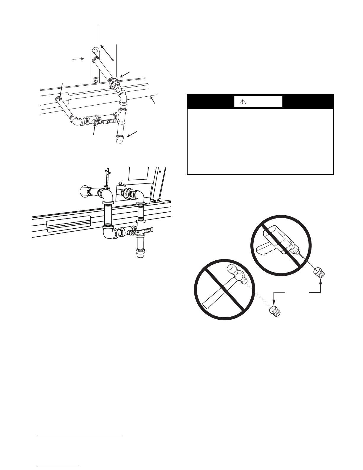
Fig. 19 — Gas Piping, Typical Curb Sidewall Piping
Drip
Leg
Shut Off
Valve
Union
Thru-Curb Adapter
Burner
Access
Panel
9” (229mm) min
Unit Base Rail
BURNER
ORIFICE
(Example 2)
disconnected from the gas valve during the testing of the piping
systems when test pressure is in excess of 0.5 psig (3450 Pa).
Pressure test the gas supply piping system at pressures equal to
or less than 0.5 psig (3450 Pa). The unit heating section must
be isolated from the gas piping system by closing the external
main manual shutoff valve and slightly opening the groundjoint union.
Check for gas leaks at the field-installed and factory-installed gas lines after all piping connections have been completed. Use soap-and-water solution (or method specified by
local codes and/or regulations).
WARNING
Failure to follow this warning could result in personal injury,
death and/or property damage.
• Connect gas pipe to unit using a backup wrench to
avoid damaging gas controls.
• Never purge a gas line into a combustion chamber.
• Never test for gas leaks with an open flame. Use a
commercially available soap solution made specifically
for the detection of leaks to check all connections.
• Use proper length of pipe to avoid stress on gas control
manifold.
NOTE: If orifice hole appears damaged or it is suspected to
have been redrilled, check orifice hole with a numbered drill bit
of correct size. Never redrill an orifice. A burr-free and squarely aligned orifice hole is essential for proper flame characteristics. See Fig. 21.
Fig. 20 — Gas Piping, Typical Thru-Base Connections
When installing the gas supply line, observe local codes
pertaining to gas pipe installations. Refer to the NFPA 54/
ANSI Z223.1 NFGC latest edition (in Canada, CAN/CSA
B149.1). In the absence of local building codes, adhere to
the following pertinent recommendations:
• Avoid low spots in long runs of pipe. Grade all pipe
1
/4 in. per every 15 ft (7 mm per every 5 m) to prevent
traps. Grade all horizontal runs downward to risers. Use
risers to connect to heating section and to meter.
• Protect all segments of piping system against physical
and thermal damage. Support all piping with appropriate
straps, hangers, etc. Use a minimum of one hanger every
6 ft (1.8 m). For pipe sizes larger than
ommendations of national codes.
• Apply joint compound (pipe dope) sparingly and only to
• Pressure-test all gas piping in accordance with local and
male threads of joint when making pipe connections. Use
only pipe dope that is resistant to action of liquefied
petroleum gases as specified by local and/or national
codes. If using PTFE (Teflon
is Double Density type and is labeled for use on gas
lines. Apply tape per manufacturer’s instructions.
national plumbing and gas codes before connecting pip-
1
) tape, ensure the material
ing to unit.
NOTE: Pressure test the gas supply system after the gas supply
piping is connected to the gas valve. The supply piping must be
1. Teflon is a registered trademark of DuPont.
1
/2 in., follow rec-
Fig. 21 — Orifice Hole
Step 12 — Install External Condensate Trap and
Line
The unit has one 3/4-in. condensate drain connection on
the end of the condensate pan and an alternate connection
on the bottom. See Fig. 22. Unit airflow configuration does
not determine which drain connection to use. Either drain
connection can be used with vertical or horizontal applications.
When using the standard side drain connection, ensure
the red plug in the alternate bottom connection is tight. Do
this before setting the unit in place. The red drain pan can be
tightened with a
To use the alternate bottom drain connection, remove the
red drain plug from the bottom connection (use a
square socket drive extension) and install it in the side drain
connection.
14
1
/2-in. square socket drive extension.
1
/2-in.
Page 15
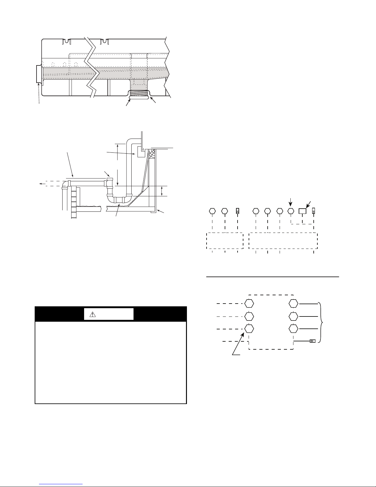
The piping for the condensate drain and external trap can
DRAIN
(FACTORY-INSTALLED)
PLUG
CONDENSATE PAN (SIDE VIEW)
STANDARD
SIDE DRAIN
ALTERNATE
BOTTOM DRAIN
NOTE: Trap should be deep enough to offset maximum unit static
difference. A 4 in. (102 mm) trap is recommended.
MINIMUM PITCH
1˝ (25 mm) PER
10´ (3 m) OF LINE
BASE RAIL
OPEN
VENT
TO ROOF
DRAIN
DRAIN PLUG
ROOF
CURB
SEE NOTE
3˝ (76 mm)
MIN
be completed after the unit is in place. See Fig. 23.
Fig. 22 — Condensate Drain Pan (Side View)
the source leads to the line side of the unit-mounted disconnect. (Check with local codes to ensure this method is acceptable in your area.) If a de-energize via unit disconnect
switch operation of the convenience outlet is desired, connect the source leads to the load side of the unit disconnect.
On a unit without a unit-mounted disconnect, connect the
source leads to compressor contactor C and indoor fan contactor IFC pressure lugs with unit field power leads.
See CONVENIENCE OUTLETS on page 16 for power
transformer connections.
Field power wires are connected to the unit at line-side
pressure lugs on compressor contactor C and indoor fan
contactor IFC (see wiring diagram label for control box
component arrangement) or at factory-installed option nonfused disconnect switch or HACR. Maximum wire size is
#2ga AWG (copper only) per pole on contactors and #2ga
AWG (copper only) per pole on optional disconnect or
HACR. See Fig. 24 and unit label diagram for field power
wiring connections.
NOTE: Unit may be equipped with short test leads (pigtails) on
the field line connection points on contactor C or optional disconnect switch. These leads are for factory-run test purposes
only; remove and discard before connecting field power wires
to unit connection points. Make field power connections directly to line connection pressure lugs only.
Units Without Disconnect or HACR Option
C
11 2 3
Equip
GR Lug
1-ph Belt Drive IFM
CIFC
11
13 13 23
or
TB
Direct Drive IFM
Equip
GR Lug
Fig. 23 — Condensate Drain Pan Piping Details
All units must have an external trap for condensate
drainage. Install a trap at least 4 in. (102 mm) deep and
protect against freeze-up. If drain line is installed downstream from the external trap, pitch the line away from the
unit at 1 in. per 10 ft (25 mm per 3 m) of run. Do not use a
pipe size smaller than the unit connection (
Step 13 — Make Electrical Connections
WARNING
Failure to follow this warning could result in personal injury
or death.
Do not use gas piping as an electrical ground. Unit cabinet must have an uninterrupted, unbroken electrical
ground to minimize the possibility of personal injury if an
electrical fault should occur. This ground may consist of
electrical wire connected to unit ground lug in control
compartment, or conduit approved for electrical ground
when installed in accordance with NEC (National Electrical Code); ANSI/NFPA 70, latest edition (in Canada, Ca-
nadian Electrical Code CSA [Canadian Standards Association] C22.1), and local electrical codes.
NOTE: Field-supplied wiring shall conform with the limitations of minimum 63°F (33°C) rise.
FIELD POWER SUPPLY — If equipped with optional
Powered Convenience Outlet, the power source leads to the
convenience outlet’s transformer primary are not factory
connected. Installer must connect these leads according to
required operation of the convenience outlet. If an alwaysenergized convenience outlet operation is desired, connect
3
/4 in.).
Disconnect
per
NEC
208/230-1-60
Ground
(GR)
L1
208/230-3-60
L2 L3
460-3-60
575-3-60
Disconnect
per
NEC
Ground
(GR)
Units With Disconnect or HACR Option
L1
L2
3 Phase Onl y 3 Phase Only
L3
Ground
(GR)
2
Optional
Disconnect
4
Switch
6
Disconnect factory test leads; discard.
1
3
5
Equip GR Lug
Fig. 24 — Power Wiring Connections
UNITS WITH FACTORY-INSTALLED NON-FUSED
DISCONNECT OR HACR — The factory-installed op-
tion non-fused disconnect (NFD) or HACR switch is located in a weatherproof enclosure located under the main control box. The manual switch handle and shaft are shipped in
the disconnect or HACR enclosure. Assemble the shaft and
handle to the switch at this point. Discard the factory test
leads (see Fig. 24).
15
Factory
Wiring
Page 16

Failure to follow this caution could result in fire, intermit-
COPPER
WIRE ONLY
ELECTRIC
DISCONNECT
SWITCH
ALUMINUM
WIRE
CONVENIENCE
OUTLET GFCI
PWD-CO FUSE
SWITCH
PWD-CO TRANSFORMER
CONTROL BOX
ACCESS PANEL
tent operation, or unsatisfactory performance.
switch and air conditioning unit. Use only copper wire.
See Fig. 25.
UNITS WITHOUT FACTORY-INSTALLED NONFUSED DISCONNECT OR HACR — When installing
units, provide a disconnect switch per NEC (National Electrical Code) of adequate size. Disconnect sizing data is provided on the unit informative plate. Locate on unit cabinet
or within sight of the unit per national or local codes. Do not
cover unit informative plate if mounting the disconnect on
the unit cabinet.
ALL UNITS — All field wiring must comply with NEC
and all local codes. Size wire based on MCA (Minimum
Circuit Amps) on the unit informative plate. See Fig. 24 and
the unit label diagram for power wiring connections to the
unit power terminal blocks and equipment ground. Maximum wire size is #2ga AWG (copper only) per pole on contactors. See Fig. 24 and unit label diagram for field power
wiring connections.
tection device (fuse or breaker) per NEC Article 440 (or local codes). Refer to unit informative data plate for MOCP
(Maximum Over-Current Protection) device size.
NOTE: Units ordered with factory installed HACR do not need
an additional ground fault and short circuit over-current protective device unless required by local codes.
quirements.
voltage shown on the nameplate. If the 208/230v unit is to
be connected to a 208v power supply, the control transformer must be rewired by moving the black wire with the
female spade connector from the 230v connection and moving it to the 200v
the transformer. Refer to unit label diagram for additional
information. Field power wires will be connected at lineside pressure lugs on the power terminal block or at factoryinstalled option non-fused disconnect.
NOTE: Check all factory and field electrical connections for
tightness.
CAUTION
Do not connect aluminum wire between disconnect
Fig. 25 — Disconnect Switch and Unit
Provide a ground fault and short circuit over-current pro-
All field wiring must comply with the NEC and local re-
All units except 208/230v units are factory wired for the
1
/4-in.
1
/4-in. male terminal on the primary side of
CONVENIENCE OUTLETS
WARNING
Failure to follow this warning could result in personal injury
or death.
Units with convenience outlet circuits may use multiple disconnects. Check convenience outlet for power status before opening unit for service. Locate its disconnect
switch, if appropriate, and open it. Lock-out and tag-out
this switch, if necessary.
Two types of convenience outlets are offered on 581J
models: non-powered and unit-powered. Both types provide
a 125-volt GFCI (ground-fault circuit interrupter) duplex receptacle rated at 15A behind a hinged waterproof access
cover, located on the end panel of the unit. See Fig. 26.
NOTE: Unit powered convenience outlets are not available as
factory installed options for single phase (-J voltage code)
models.
Fig. 26 — Convenience Outlet Location
Installing Weatherproof Cover
— A weatherproof while-inuse cover for the factory-installed convenience outlets is now
required by UL standards. This cover cannot be factorymounted due its depth; it must be installed at unit installation.
For shipment, the convenience outlet is covered with a blank
cover plate.
The weatherproof cover kit is shipped in the unit’s control box. The kit includes the hinged cover, a backing plate,
and gasket.
WARNING
Failure to follow this warning could result in personal injury
or death.
Disconnect all power to unit and convenience outlet.
Lock-out and tag-out all power.
1. Remove the blank cover plate at the convenience out-
let; discard the blank cover.
2. Loosen the two screws at the GFCI duplex outlet, until
approximately
1/
in. (13 mm) under screw heads is
2
exposed. Press the gasket over the screw heads.
16
Page 17
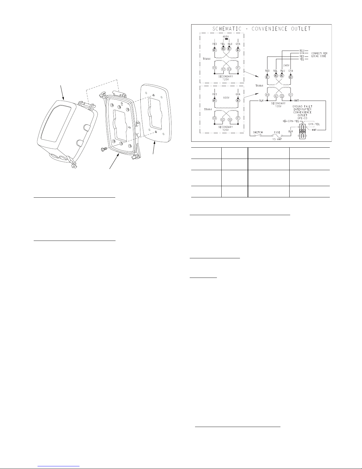
3. Slip the backing plate over the screw heads at the key-
T
OP
T
O
P
TOP
W
ET
L
OCA
TI
ONS
W
E
T
L
O
C
A
T
I
O
NS
COVER - WHILE-IN-USE
WEATHERPROOF
BASEPLATE FOR
GFCI RECEPTACLE
GASKET
GFCI RECEPTACLE
NOT INCLUDED
UNIT
VOLTAGE
CONNECT ASPRIMARY
CONNECTIONS
TRANSFORMER
TERMINALS
208, 230 240
L1: RED + YEL
L2: BLU + GRA
H1 + H3
H2 + H4
460 480
L1: RED
Splice BLU + YEL
L2: GRA
H1
H2 + H3
H4
575 600
L1: RED
L2: GRA
H1
H2
4. Mount the weatherproof cover to the backing plate as
5. Remove two slot fillers in the bottom of the cover to
6. Check for full closing and latching.
Non-Powered Convenience Outlet
field installation of a general-purpose 125v 15A circuit
powered from a source elsewhere in the building. Observe
national and local codes when selecting wire size, fuse or
breaker requirements, and disconnect switch size and location. Route 125v power supply conductors into the bottom
of the utility box containing the duplex receptacle.
Unit-Powered Convenience Outlet
transformer is factory-installed to step down the main power supply voltage to the unit to 115v at the duplex receptacle. This option also includes a manual switch with fuse, located in a utility box and mounted on a bracket behind the
convenience outlet; access is through the unit’s control box
access panel. See Fig. 26.
are not factory-connected. Selection of primary power
source is a customer option. If local codes permit, the transformer primary leads can be connected at the line-side terminals on the unit-mounted non-fused disconnect or HACR
breaker switch; this will provide service power to the unit
when the unit disconnect switch or HACR switch is open.
Other connection methods will result in the convenience
outlet circuit being de-energized when the unit disconnect
or HACR switch is open. See Fig. 28.
hole slots and align with the gasket; tighten the two
screws until snug (do not over-tighten).
shown in Fig. 27.
permit service tool cords to exit the cover.
Fig. 27 — Weatherproof Cover Installation
— This type requires the
— A unit-mounted
The primary leads to the convenience outlet transformer
Fig. 28 — Powered Convenience Outlet Wiring
Using Unit-Mounted Convenience Outlets
— Units with
unit-mounted convenience outlet circuits will often require
that two disconnects be opened to de-energize all power to
the unit. Treat all units as electrically energized until the
convenience outlet power is also checked and de-energization is confirmed. Observe National Electrical Code Article
210, Branch Circuits, for use of convenience outlets.
Fuse On Power Type
“Fusetron”
1
T-15, non-renewable screw-in (Edison base)
— The factory fuse is a Bussman
type plug fuse.
Duty Cycle
— The unit-powered convenience outlet has a
duty cycle limitation. The transformer is intended to provide
power on an intermittent basis for service tools, lamps, etc;
it is not intended to provide 15-amps loading for continuous
duty loads (such as electric heaters for overnight use). Observe a 50% limit on circuit loading above 8 amps.
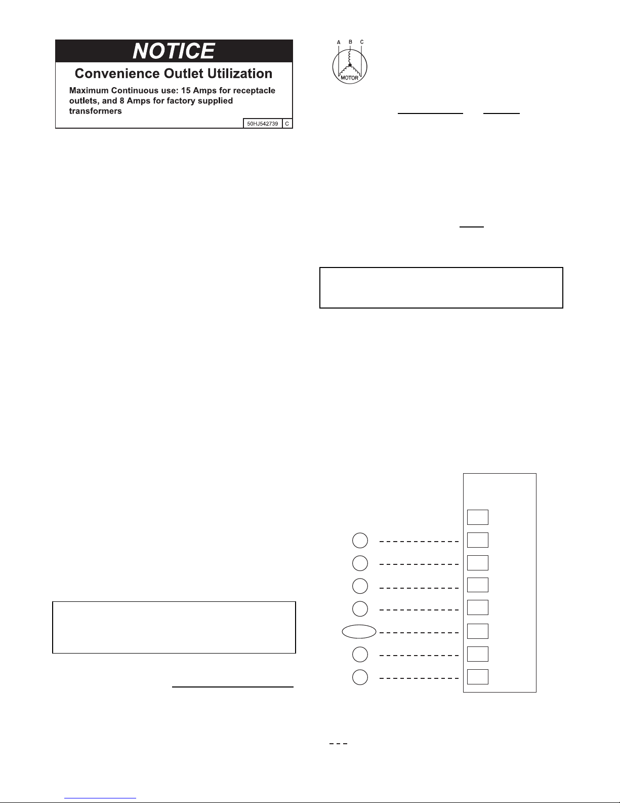
Convenience outlet usage rating:
• Continuous usage: 8 amps maximum
• Intermittent usage: Up to 15 amps maximum for up to 2
hours maximum
Test the GFCI receptacle by pressing the TEST button on
the face of the receptacle to trip and open the receptacle.
Check for proper grounding wires and power line phasing if
the GFCI receptacle does not trip as required. Press the RESET button to clear the tripped condition.
1. Bussman and Fusetron are trademarks of Cooper
Technologies Company.
17
Page 18
AB = 224 v
X
C
G
W2
C
W2
G
W1
O/B/Y2
Y2
R
W1
R
Y1
Y1
T
H
E
R
M
O
S
T
A
T
(Note 1)
(Note 2)
Note 1: Typical multi-function marking. Follow manufacturer’s conguration
Instructions to select Y2.
Note 2: Y2 to Y2 connection required on single-stage cooling units when
integrated economizer function is desired.
Field Wiring
Central
Te r mi n al
Board
Typical
Thermostat
Connections
BC = 231 v
AC = 226 v
Average Voltage =
224 + 231 + 226
33
681
=
= 227
Fig. 29 — Convenience Outlet Utilization
Notice Label
FACTORY-OPTION THRU-BASE CONNECTIONS
(ELECTRICAL CONNECTIONS) — This service con-
nection kit consists of a
(brass), a
1
/2-in. electrical bulkhead connector, and a 3/4-in.
1
/2-in. NPT gas adapter fitting
electrical bulkhead connector, all factory-installed in the
embossed (raised) section of the unit basepan in the condenser section. The
low-voltage control wires to pass through the basepan. The
1
/2-in. electrical bulkhead connector allows the high-voltage
3
/4-in. bulkhead connector enables the
power wires to pass through the basepan. See Fig. 16 on
page 13.
Check tightness of connector lock nuts before connecting
electrical conduits.
Field-supplied and field-installed liquid tight conduit
connectors and conduit may be attached to the connectors
on the basepan. Pull correctly rated high voltage and low
voltage through appropriate conduits. Connect the power
conduit to the internal disconnect (if unit is so equipped) or
to the external disconnect (through unit side panel). A hole
must be field cut in the main control box bottom on the left
side so the 24-v control connections can be made. Connect
the control power conduit to the unit control box at this
hole.
UNITS WITHOUT THRU-BASE CONNECTIONS
(ELECTRICAL CONNECTIONS)
1. Install power wiring conduit through side panel open-
ings. Install conduit between disconnect and control
box.
2. Install power lines to terminal connections as shown in
Fig. 24 on page 15.
Voltage to compressor terminals during operation must
be within voltage range indicated on unit nameplate. On 3phase units, voltages between phases must be balanced
within 2% and the current within 10%. Use the formula
shown in the example below to determine the percent of
voltage imbalance. Operation on improper line voltage or
excessive phase imbalance constitutes abuse and may cause
damage to electrical components. Such operation would invalidate any applicable Bryant warranty.
Unbalanced 3-Phase Supply Voltage:
IMPORTANT: Never operate a motor where a phase
imbalance in supply voltage is greater than 2%. Use
the following formula to determine the percentage of
voltage imbalance.
% Voltage Imbalance = 100 x
Example: Supply voltage is 230-3-60.
max voltage deviation from
average voltage
average voltage
Determine maximum deviation from average voltage.
(AB) 227
– 224 = 3 v
(BC) 231 – 227 = 4 v
(AC) 227
– 226 = 1 v
Maximum deviation is 4 v.
Determine percent of voltage imbalance.
% Voltage Imbalance = 100x
4
226
=1.76%
This amount of phase imbalance is satisfactory as it is be-
low the maximum allowable 2%.
IMPORTANT: If the supply voltage phase imbalance
is more than 2%, contact your local electric utility
company immediately.
NOTE: Check all factory and field electrical connections for
tightness.
FIELD CONTROL WIRING — The 581J unit requires
an external temperature control device. This device can be a
thermostat emulation device provided as part of a third party Building Management System.
THERMOSTAT — Install a Bryant-approved accessory
thermostat according to installation instructions included
with the accessory. For complete economizer function, select a two-stage cooling thermostat. Locate the thermostat
accessory on a solid wall in the conditioned space to sense
average temperature in accordance with the thermostat installation instructions. Typical low-voltage connections are
shown in Fig. 30.
Fig. 30 — Low-Voltage Thermostat Connections
18
Page 19
If the thermostat contains a logic circuit requiring 24v
power, use a thermostat cable or equivalent single leads of
different colors with minimum of seven leads. If the thermostat does not require a 24v source (no “C” connection required), use a thermostat cable or equivalent with minimum
of six leads. Check the thermostat installation instructions
for additional features which might require additional conductors in the cable.
For wire runs up to 50 ft. (15 m), use no. 18 AWG
(American Wire Gage) insulated wire [95°F (35°C) minimum]. For 50 to 75 ft. (15 to 23 m), use no. 16 AWG insulated wire [95°F (35°C) minimum]. For over 75 ft. (23 m),
use no. 14 AWG insulated wire [95°F (35°C) minimum].
Wire sizes larger than no. 18 AWG cannot be directly connected to the thermostat and will require a junction box and
splice at the thermostat.
Thermostat Wiring, Units Without Thru-Base Connection
Kit — Pass the thermostat control wires through the hole
provided in the corner post; then feed the wires through the
raceway built into the corner post to the control box. Pull
the wires over to the terminal strip on the upper-left corner
of the Controls Connection Board. See Fig. 31.
NOTE: If thru-the-bottom connections accessory is used, refer
to the accessory installation instructions for information on
routing power and control wiring.
RACEWAY
HOLE IN END PANEL (HIDDEN)
Fig. 31 — Field Control Wiring Raceway
HEAT ANTICIPATOR SETTINGS — Set heat anticipa-
tor settings at 0.14 amp for the first stage and 0.14 amp for
second-stage heating, when available.
Perfect Humidity™ Control Connections
PERFECT HUMIDITY — SPACE RH CONTROLLER
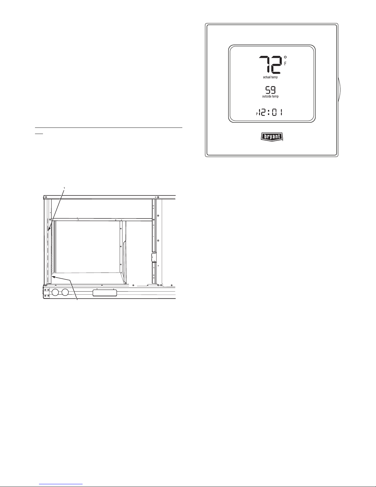
Fig. 32 — Edge Programmable Thermostat
To connect a field- supplied humidistat:
1. Route the humidistat 2-conductor cable (field -supplied) through the hole provided in the unit corner
post.
2. Feed wires through the raceway built into the corner post
(see Fig. 31) to the 24-v barrier located on the left side of
the control box. The raceway provides the UL-required
clearance between high-voltage and low-voltage wiring.
3. Use wire nuts to connect humidistat cable to two PINK
leads in the low–voltage wiring as shown in Fig. 33.
To connect the Edge Programmable Thermidistat (T6-
PRH01- A):
1. Route the Edge Programmable Thermostat multi-conductor cable (field-supplied) through the hole provided
in the unit corner post.
2. Feed wires through the raceway build into the corner post
(see Fig. 31) to the 24-v barrier located on the left side of
the control box. The raceway provides the UL-required
clearance between high-voltage and low-voltage wiring.
3. The Edge Programmable Thermostat has dry contacts at
terminals D1 and D2 for dehumidification operation (see
Fig. 33). The dry contacts must be wired between CTB
terminal R and the PINK lead to the LTLO switch with
field-supplied wire nuts (See Fig. 33). Refer to the installation instructions included with the Bryant Edge Programmable Thermidistat device for more information.
NOTE: Perfect Humidity is a factory installed option which is
only available for units equipped with belt-drive motors. Perfect Humidity is not available for single phase (-J voltage code)
models.
The Perfect Humidity dehumidification system requires a
field-supplied and installed space relative humidity control device. This device may be a separate humidistat control (contact
closes on rise in space RH above control setpoint) or a combination thermostat-humidistat control device such as Bryant’s
®
Edge
Pro Thermidistat with isolated contact set for dehumidi-
fication control (see Fig. 32).
19
Page 20

Fig. 33 — Typical Rooftop Unit with Perfect Humidity
Rc
Rh
W1
G
Y2
C
O/W2/B
Y1
OAT
RRS
SRTN
HUM
D1
D2
V+
Vg
X*
C
G
W2
W1
Y2
Y1
R
EDGE Pro THERMIDISTAT
Unit CTB
THERMOSTAT
*Connection not required.
Perfect Humidity™ FIOP
Adaptive Dehumidification System
and Edge
®
Pro Thermidistat Device
™
Fig. 34 — Typical Perfect Humidity Adaptive Dehumidification System Humidistat Wiring
20
Page 21
EconoMi$er® X (Factory-Installed Option)
PRODUCT DESCRIPTION
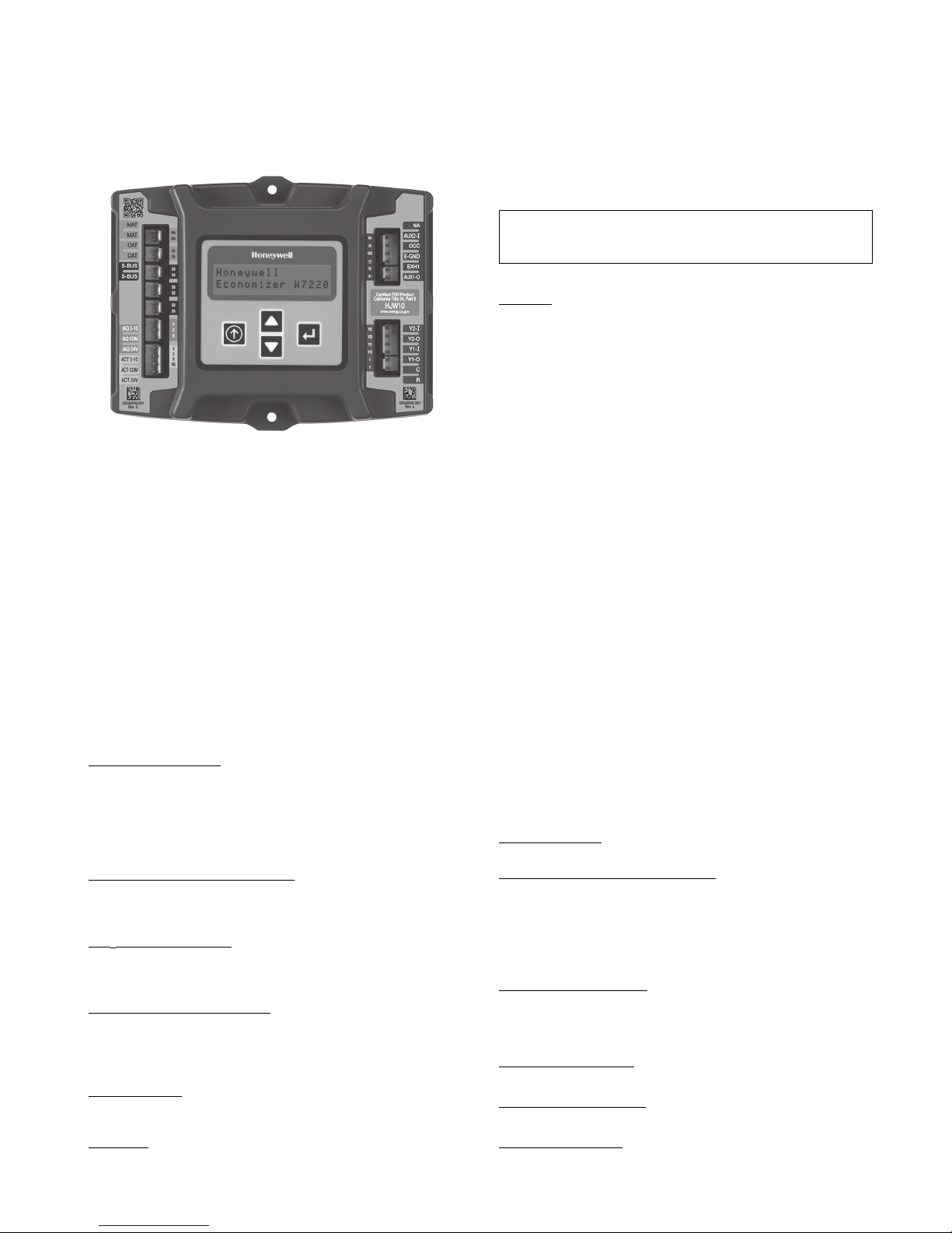
The EconoMi$er X system is an expandable economizer
control system, which includes a W7220 economizer module
(controller) with an LCD and keypad (See Fig. 35). The
W7220 can be configured with optional sensors.
Fig. 35 — W7220 Economizer Module
The W7220 economizer module can be used as a standalone economizer module wired directly to a commercial setback space thermostat and sensors to provide outside air drybulb economizer control.
The W7220 economizer module can be connected to optional sensors for single or differential enthalpy control. The
W7220 economizer module provides power and communications for the sensors.
The W7220 economizer module automatically detects sensors by polling to determine which sensors are present. If a
sensor loses communications after it has been detected, the
W7220 economizer controller indicates a device fail error on
its LCD.
SYSTEM COMPONENTS — The EconoMi$er X system
includes an economizer module, 20k mixed air sensor, damper
actuator, and either a 20k outdoor air temperature sensor or SBus enthalpy sensors.
Economizer Module:
EconoMi$er X system. The module is mounted in the unit’s
control box, and includes the user interface for the system. The
W7220 economizer module provides the basic inputs and outputs to provide simple economizer control. When used with the
optional sensors, the economizer module provides more advanced economizer functionality.
S-Bus Enthalpy Control Sensors:
tion temperature and humidity sensor which is powered by and
communicates on the S-Bus. Up to three sensors may be configured with the W7220 economizer module.
CO
Sensor (optional): The sensor can be added for Demand
2
Controlled Ventilation (DCV).
SPECIFICATIONS
W7220 Economizer Module:
with 2 to 10 Vdc or bus communicating actuator. The module
includes terminals for CO
Outdoor Dry Bulb sensor. Enthalpy and other options are available with bus sensors.
User Interface:
rameters, checkout tests, and alarm and error conditions with a
2-line 16 character LCD display and four button keypad.
Electrical
Rated Voltage — 20 to 30 Vac RMS, 50/60 Hz
The module is the core of the
The sensor is a combina-
The module is designed for use
sensor, Mixed Air sensor, and an
2
Provides status for normal operation, setup pa-
Transformer — 100 va maximum system input
Nominal Power Consumption (at 24 Vac, 60 Hz) — 11.5
VA without sensors or actuators
Relay Digital Output Rating at 30 Vac (maximum power
from Class 2 input only) — 1.5A run:
3.5A inrush at 0.45PF (200,000 cycles) or
7.5A inrush at 0.45PF (100,000 cycles)
External Sensors Power Output — 21 Vdc ± 5% at 48mA
IMPORTANT: All inputs and outputs must be Class 2
wiring.
INPUTS
Sensors:
NOTE: A Mixed Air (MA) analog sensor is required on all
W7220 units; either an Outdoor Air (OA) sensor for dry bulb
change over or an OA bus sensor for outdoor enthalpy change
over is required in addition to the MA sensor. An additional
Return Air (RA) bus sensor can be added to the system for differential enthalpy or dry bulb changeover. For differential dry
bulb changeover a 20k ohm sensor is required in the OA and a
bus sensor in the RA. DIP switch on RA bus sensor must be
set in the RA position.
Dry Bulb Temperature (optional) and Mixed Air (required),
20k NTC
2-wire (18 to 22 AWG);
Temperature range -40 to 150°F (-40 to 65°C)
Temperature accuracy -0°F/+2°F
Temperature and Humidity, C7400S1000 (optional)
S-Bus; 2-wire (18 to 22 AWG)
Temperature: range -40 to 150°F (-40 to 65°C)
Temperature accuracy -0°F/+2°F
Humidity: range 0 to 100% RH with 5% accuracy.
NOTE: Up to three (3) S-Bus sensors may be connected to the
W7220 economizer module. For outdoor air (OA), return air
(RA) and discharge (supply) air (DA).
4 Binary Inputs
1-wire 24 Vac + common GND.
24 Vac power supply
20 to 30 Vac 50/60Hz; 100 VA Class 2 transformer.
OUTPUTS
Actuator Signal:
2-10 Vdc; minimum actuator impedance is
2k ohm; bus two-wire output for bus communicating actuators.
Exhaust fan, Y1, Y2 and AUX1 O:
All Relay Outputs (at 30 Vac):
Running: 1.5A maximum
Inrush: 7.5A maximum
ENVIRONMENTAL
Operating Temperature:
-40 to 150°F (-40 to 65°C).
Exception of display operation down to -4°F with full
recovery at -4°F from exposure to -40°F
Storage Temperature:
-40 to 150°F (-40 to 65°C)
Shipping Temperature:
-40 to 150°F (- 40 to 65°C)
Relative Humidity:
5% to 95% RH non-condensing
21
Page 22
ECONOMIZER MODULE WIRING DETAILS —
NA
AUX2-
OCC
E-GND
EXH1
AUX1-O
Y2-
Y1-
Y2-O
Y1-O
C
R
50048848-002
Rev. A
NA
A2
OCC
EX
A1
Y2I
Y2O
Y1I
Y1O
C
R
Cert Product
California Title 24, Part 6
HJW10
www.energy.ca.gov
MAT
MAT
OAT
OAT
S-BUS
S-BUS
IAQ 2-10
IAQ COM
IAQ 24V
ACT 2-10
ACT CO M
ACT 24V
MA
MA
OA
OA
SB
SB
SB
SB
SB
SB
V
C
R
V
C
R
NA
50040839-001
Rev. G
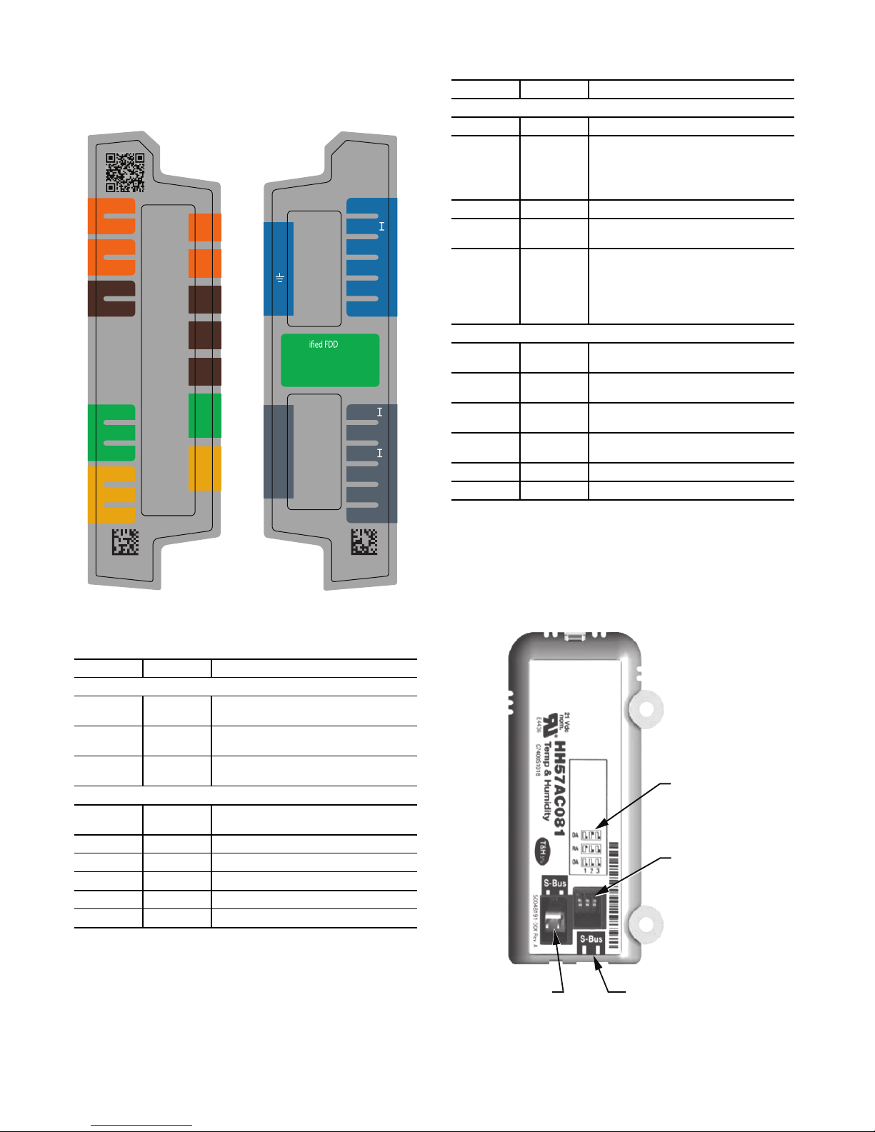
Use Fig. 36 and Tables 5 and 6 to locate the wiring terminals
for the Economizer module.
NOTE: The four terminal blocks are removable. Slide out each
terminal block, wire it, and then slide it back into place.
Table 6 — Economizer Module - Right Hand Terminal
Blocks
LABEL TYPE DESCRIPTION
Top Right Terminal Blocks
AUX2 I 24 vac IN The first terminal is not used.
Shut Down (SD) or HEAT (W)
OCC 24 vac IN
E-GND E-GND Occupied/Unoccupied Input
EXH1
AUX1 O
24 vac
OUT
24 vac
OUT
Bottom Right Terminal Blocks
Y2-I 24 vac IN
Y2-O
24 vac
OUT
Y1-I 24 vac IN
Y1-O
24 vac
OUT
C COM 24 vac Common
R 24 vac 24 vac Power (hot)
Conventional only
and
Heat Pump Changeover (O-B) in Heat
Pump mode.
Exhaust Fan 1 Output
Programmable:
Exhaust fan 2 output
or
ERV
or
System alarm output
Y2 in - Cooling Stage 2 Input from
space thermostat
Y2 out - Cooling Stage 2 Output to
stage 2 mechanical cooling
Y1 in - Cooling Stage 2 Input from
space thermostat
Y1 out - Cooling Stage 2 Output to
stage 2 mechanical cooling
Fig. 36 — W7220 Wiring Terminals
Table 5 — Economizer Module - Left Hand Terminal
Blocks
LABEL TYPE DESCRIPTION
Top Left Terminal Block
MAT
MAT
OAT
OAT
S-BUS
S-BUS
IAQ 2-10 2-10 vdc
IAQ COM COM Air Quality Sensor Common
IAQ 24V 24 vac Air Quality Sensor 24 vac Source
ACT 2-10 2-10 vdc Damper Actuator Output (2-10 vdc)
ACT COM COM Damper Actuator Output Common
ACT 24v 24 vac Damper Actuator 24 vac Source
*Sylk is a trademark of Honeywell International Inc.
20k NTC
and COM
20k NTC
and COM
S-BUS
(Sylk* Bus)
Bottom Left Terminal Block
Mixed Air Temperature Sensor (Polarity
Insensitive Connection)
Outdoor Air Temperature Sensor
(Polarity Insensitive Connection)
Enthalpy Control Sensor
(Polarity Insensitive Connection)
Air Quality Sensor Input (e.g. CO
sensor)
2
S-BUS SENSOR WIRING — The labels on the sensors and
controller are color coded for ease of installation. Orange labeled sensors can only be wired to orange terminals on the controller. Brown labeled sensors can only be wired to S-bus
(brown) terminals. Use Fig. 37 and Table 10 to locate the wiring terminals for each S-Bus sensor.
Use Fig. 37 and Table 7 to locate the wiring terminals for
each enthalpy control sensor.
DIP
SWITCH
LABEL
DIP
SWITCHES
(3)
S-BUS
TERMINALS
(1 AND 2)
S-BUS
2 PIN SIDE
CONNECTOR
Fig. 37 — S-Bus Sensor DIP Switches
22
Page 23

CO2 SENSOR
24V
ANALOG
OUT
L1
(HOT)
L2
RED
BLACK
YELLOW
BROWN
ORANGE
GREEN
+
–
POWER SUPPLY. PROVIDE DISCONNECT
MEANS AND OVERLOAD PROTECTION
AS REQUIRED.
1
1
Table 7 — HH57AC081 Sensor Wiring Terminations
TERMINAL
NUMBER LABEL
1 S-BUS S-BUS
2 S-BUS S-BUS
TYPE DESCRIPTION
Communications
(Enthalpy Control
Sensor Bus)
Communications
(Enthalpy Control
Sensor Bus)
Use Fig. 37 and Table 8 to set the DIP switches for the
desired use of the sensor.
Table 8 — HH57AC081 Sensor DIP Switch
DIP SWITCH POSITIONS FOR SWITCHES 1, 2, AND 3
USE
DA OFF ON OFF
RA ON OFF OFF
OA OFF OFF OFF
123
NOTE: When a S-Bus sensor is connected to an existing network, it will take 60 minutes for the network to recognize and
auto-configure itself to use the new sensor.
During the 60-minute setup period, no alarms for sensor
failures (except SAT) will be issued and no economizing function will be available.
CO
SENSOR WIRING — When using a CO2 sensor the
2
black and brown common wires are internally connected and
only one is connected to “IAQ COM” on the W7220. Use the
power from the W7220 to power the CO
sensor OR make sure
2
the ground for the power supplies are common. See Fig. 38 for
CO
sensor wiring.
2
Fig. 38 — CO
Sensor Wiring
2
INTERFACE OVERVIEW — This section describes how
to use the Economizer’s user interface for:
• Keypad and menu navigation
• Settings and parameter changes
• Menu structure and selection
USER INTERFACE — The user interface consists of a 2line LCD display and a 4-button keypad on the front of the
economizer controller.
KEYPAD — The four navigation buttons (see Fig. 39) are
used to scroll through the menus and menu items, select menu
items, and to change parameter and configuration settings.
To use the keypad when working with menus:
• Press the ▲ (Up arrow) button to move to the previous
menu.
• Press the ▼ (Down arrow) button to move to the next
menu.
S-BUS
S-BUS
• Press the (Enter) button to display the first item in
the currently displayed menu.
Fig. 39 — W7220 Controller Navigation Buttons
Press the (Menu Up/Exit) button to exit a menu’s
item and return to the list of menus. To use the keypad when
working with Setpoints, System and Advanced Settings,
Checkout tests and Alarms:
1. Navigate to the desired menu.
2. Press the (Enter) button to display the first item in the
currently displayed menu.
3. Use the ▲ and ▼ buttons to scroll to the desired parameter.
4. Press the (Enter) button to display the value of the
currently displayed item.
5. Press the ▲ button to increase (change) the displayed parameter value.
6. Press the ▼ button to decrease (change) the displayed parameter value.
NOTE: When values are displayed, pressing and holding
the ▲ or ▼ button causes the display to automatically increment.
7. Press the (Enter) button to accept the displayed value
and store it in nonvolatile RAM. “CHANGE STORED”
displays.
8. Press the (Enter) button to return to the current menu
parameter.
9. Press the (Menu Up/Exit) button to return to the previous menu.
MENU STRUCTURE — Table 9 illustrates the complete hierarchy of menus and parameters for the EconoMi$er
®
X sys-
tem.
The Menus in display order are:
•STATUS
• SETPOINTS
•SYSTEM SETUP
• ADVANCED SETUP
• CHECKOUT
•ALARMS
IMPORTANT: Table 9 illustrates the complete hierarchy. Menu parameters may be different depending on
the configuration. For example, if there is no DCV
(CO
) sensor, then none of the DCV parameters appear
2
and only MIN POS will display. If there is a CO
sen-
2
sor, the DCV MIN and DCV MAX will appear AND if
there is a 2 speed fan DCV MIN (high and low speed)
and DCV MAX (high and low speed will appear).
23
Page 24

NOTE: Some parameters in the menus use the letters MA or
MAT, indicating a mixed air temperature sensor location
before the cooling coil. This unit application has the control
sensor located after the cooling coil, in the fan section, where it
is designated as (Cooling) Supply Air Temperature or SAT
sensor.
SETUP AND CONFIGURATION — Before being placed
into service, the W7220 Economizer module must be setup and
configured for the installed system.
IMPORTANT: During setup, the economizer module is
live at all times.
The setup process uses a hierarchical menu structure that is
easy to use. Press the ▲ and ▼ arrow buttons to move forward
and backward through the menus and press the (Enter)
button to select and confirm setup item changes.
TIME-OUT AND SCREENSAVER — When no buttons
have been pressed for 10 minutes, the LCD displays a screen
saver, which cycles through the Status items. Each Status items
displays in turn and cycles to the next item after 5 seconds.
24
Page 25

MENU PARAMETER
ECONO AVAIL NO YES/NO
ECONOMIZING NO YES/NO
OCCUPIED NO YES/NO
HEAT PUMP N/A
COOL Y1—IN OFF ON/OFF
COOL Y1—OUT OFF ON/OFF
COOL Y2—IN OFF ON/OFF
COOL Y2—OUT OFF ON/OFF
STATUS
MA TEMP _ _ . _ F 0 to 140°F
DA TEMP _ _ . _ F 0 to 140°F
OA TEMP _ _ . _ F -40 to 140°F
OA HUM _ _ % 0 to 100%
RA TEMP _ _ . _ F 0 to 140°F
RA HUM _ _ % 0 to 100%
IN CO2 _ _ _ ppm 0 TO 2000 ppm
DCV STATUS N/A ON/OFF
DAMPER OUT 2.0v 2.0 TO 10.0v Displays voltage output to the damper actuator.
ACT POS N/A 0 to 100% Displays actual position of outdoor air damper actuator
Table 9 — Menu Structure
PARAMETER
DEFAULT
VALUE
PARAMETER
RANGE AND
INCREMENT
COOL
HEAT
NOTES
FIRST STAGE COOLING DEMAND (Y1–IN)
YES = economizing available; the system can use outside air for free
cooling when required
FIRST STAGE COOLING RELAY OUTPUT
YES = outside air being used for 1 stage cooling
OCCUPIED
YES = OCC signal received from space thermostat or
unitary controller
YES = 24 Vac on terminal OCC
NO = 0 Vac on terminal OCC
HEAT PUMP MODE
Displays COOL or HEAT when system is set to heat pump
(Non-conventional)
FIRST STAGE COOLING DEMAND (Y1-IN)
Y1–I signal from space thermostat or unitary controller for cooling stage
1.
ON = 24 Vac on terminal Y1–I
OFF = 0 Vac on terminal Y1–I
FIRST STAGE COOLING RELAY OUTPUT
Cool stage 1 Relay Output to stage 1 mechanical cooling
(Y1–OUT terminal)
SECOND STAGE COOLING DEMAND (Y2–IN)
Y2–I signal from space thermostat our unitary controller for second
stage cooling.
ON = 24 Vac on terminal Y2–I
OFF = 0 Vac on terminal Y2–I
SECOND STAGE COOLING RELAY OUTPUT
Cool Stage 2 Relay Output to mechanical cooling
(Y2–OUT terminal)
SUPPLY AIR TEMPERATURE, Cooling Mode
Displays value of measured mixed air from MAT sensor.
Displays _ _ . _ F if not connected, short or out-of-range.
DISCHARGE AIR TEMPERATURE, after Heating section
Displays when Discharge Air sensor is connected and displays measured discharge temperature.
Displays _ _ . _F if sensor sends invalid value, if not connected, short or
out-of-range.
OUTSIDE AIR TEMP
Displays measured value of outdoor air temperature.
Displays _ _ . _F if sensor sends invalid value, short or out-of-range.
OUTSIDE AIR RELATIVE HUMIDITY
Displays measured value of outdoor humidity from OA sensor.
Displays _ _% if not connected short, or out-of-range.
RETURN AIR TEMPERATURE
Displays measured value of return air temperature from
RAT sensor.
Displays _ _ . _ F if sensor sends invalid value, if not connected, short or
out-of-range
RETURN AIR RELATIVE HUMIDITY
Displays measured value of return air humidity from RA sensor.
Displays _ _% if sensor sends invalid value, if not connected, short or
out-of-range
SPACE/RETURN AIR CO
Displays value of measured CO2 from CO2 sensor. Invalid if not connected, short or out-of-range
DEMAND CONTROLLED VENTILATION STATUS
Displays ON if above setpoint and OFF if below setpoint, and ONLY if a
sensor is connected.
CO
2
2
25
Page 26

MENU PARAMETER
ACT COUNT N/A 1 to 65535 Displays number of times actuator has cycled.
ACTUATOR N/A OK/Alarm (on
EXH1 OUT OFF ON/OFF EXHAUST STAGE 1 RELAY OUTPUT
STATUS
(CONT)
EXH2 OUT OFF ON/OFF EXHAUST STAGE 2 RELAY OUTPUT
MECH COOL ON
HEAT STAGES ON
FAN SPEED N/A LOW or HIGH SUPPLY FAN SPEED
W (HEAT ON) N/A ON/OFF HEAT DEMAND STATUS
MAT SET 53°F
LOW T LOCK 32°F
DRYBLB SET 63°F
ENTH CURVE ES3
DCV SET 1100ppm
MIN POS 2.8 V 2 to 10 Vdc
VENTMAX
With 2-speed fan units
VENTMAX L (low speed fan)
and VENTMAX H (high
speed fan) settings are
required
SETPOINTS
VENTMIN
With 2-speed
fan units VENTMIN L (low
speed fan) and VENTMIN
H (high speed fan) set
ERV OAT SP 32°F
EXH1 SET
With 2-speed fan units Exh1
L (low speed fan) and Exh1
H (high speed fan) settings
are required
EXH2 SET
With 2-speed fan units Exh2
L (low speed fan) and Exh2
H (high speed fan) settings
are required
Table 9 — Menu Structure (cont)
PARAMETER
DEFAULT
VALUE
ERV OFF ON/OFF ENERGY RECOVERY VENTILATOR
or
0 0, 1, or 2 Displays stage of mechanical cooling that is active.
2.8 V
2.25 V
50%
75%
PARAMETER
RANGE AND
INCREMENT
Alarm menu)
38 to 65°F; incre-
ment by 1
-45 to 80°F;
increment by 1
48 to 80°F; incre-
ment by 1
ES1,ES2,ES3,ES
4, or ES5
500 to 2000ppm;
increment by 100
2 to 10 Vdc
100 to 9990 cfm;
increment by 10
2 to 10 Vdc
2 to 10 Vdc or 100
to 9990 cfm incre-
ment by 10
100 to 9990 cfm;
increment by 10
2 to 10 Vdc
0 to 50°F; incre-
ment by 1
0 to 100%;incre-
ment by 1
0 to 100%; incre-
ment by 1
NOTES
1 cycles equals 180 deg. of actuator movement in any direction.
Displays ERROR if voltage or torque is below actuator range.
Output of EXH1 terminal:
ON = relay closed
OFF = relay open
Output of AUX terminal; displays only if AUX = EXH2
Output of AUX terminal; displays only if AUX = ERV
Displays the stage of heat pump heating that is active.
Displays speed setting of fan on a 2-speed fan unit.
Displays status of heat demand on a 2-speed fan unit.
SUPPLY AIR SETPOINT
Setpoint determines where the economizer will modulate the OA
damper to maintain the mixed air temperature.
COMPRESSOR LOW TEMPERATURE LOCKOUT
Setpoint determines outdoor temperature when the mechanical cooling
cannot be turned on. Commonly referred to as the Compressor lockout.
OA DRY BULB TEMPERATURE CHANGEOVER SETPOINT
Setpoint determines where the economizer will assume outdoor air temperature is good for free cooling; e.g.; at 63°F unit will economize at
62°F and below and not economize at 64°F and above. There is a 2°F
deadband.
ENTHALPY CHANGEOVER CURVE
Enthalpy boundary “curves” for economizing using single enthalpy.
DEMAND CONTROLLED VENTILATION
Displays only if CO
Ventilation of space. Above the setpoint, the OA dampers will modulate
open to bring in additional OA to maintain a space ppm level below the
setpoint.
VENTILATION MINIMUM POSITION
Displays ONLY if a CO
DCV MAXIMUM DAMPER POSITION
Displays only if a CO
max cfm) setpoint. Displays 2 to 10 V if <3 sensors (RA,OA, and MA). In
AUTO mode dampers controlled by CFM.
If OA, MA, RA, and CO
is set to AUTO mode, the OA dampers are controlled by CFM and displays from 100 to 9990 CFM.
With 2-speed fan units VENT L (low speed fan) and MIN POS H (high
speed fan) settings are required. Default for VENTMAX L is 3.2V and
VENTMAX H is 2.8V
DCV MINIMUM DAMPER POSITION
Displays only if a CO
cfm) setpoint. Displays 2 to 10 V if <3 sensors (RA, OA, and MA). Va is
only set if DCV is used. This is the ventilation for less than maximum
occupancy of the space. In AUTO mode dampers controlled by CFM.
If OA, MA, RA, and CO
is set to AUTO mode, the OA dampers are controlled by CFM and displays from 100 to 9990 CFM.
With 2-speed fan units VENTMIN L (low speed fan) and MIN POS H
(high speed fan) settings are required. Default for VENTMIN L is 3.2V
and VENTMIN H is 2.8V
ENERGY RECOVERY VENTILATOR UNIT OUTDOOR AIR TEMPERATURE SETPOINT
Only when AUX1 O = ERV
EXHAUST FAN STAGE 1 SETPOINT
Setpoint for OA damper position when exhaust fan 1 is powered by the
economizer.
With 2-speed fan units Exh1 L (low speed fan) and Exh1 H (high speed
fan) settings are required. Default for Exh1 L is 65% and Exh1 H is 50%
EXHAUST FAN STAGE 2 SETPOINT
Setpoint for OA damper position when exhaust fan 2 is powered by the
economizer. Only used when AUX1 O is set to EHX2.
With 2-speed fan units Exh2 L (low speed fan) and Exh2 H (high speed
fan) settings are required. Default for Exh2 L is 80% and Exh2 H is 75%
sensor is connected. Setpoint for Demand Control
2
sensor is NOT connected.
2
sensor is connected. Used for Vbz (ventilation
2
sensors are connected and DCV CAL ENABLE
2
sensor is connected. Used for Ba (ventilation min
2
sensors are connected and DCV CAL ENABLE
2
26
Page 27

MENU PARAMETER
INSTALL 01/01/10 N/A Display order = MM/DD/YY
UNITS DEG F F or C Sets economizer controller in degrees Fahrenheit or Celsius
EQUIPMENT CONV Conventional or HPCONV = conventional;
AUX2 IN W SD/W or HP(O)/
FAN SPEED 2 speed 1 speed/2 speed Sets the economizer controller for operation of 1 speed or 2 speed sup-
SYSTEM
SETUP
FAN CFM 5000cfm 100 to 15000 cfm;
AUX1 OUT NONE NONE
FACTORY DEFAULT NO NO or YES Resets all set points to factory defaults when set to YES. LCD
MA LO SET 45°F 35 to 55°F;
FREEZE POS CLO CLO or MIN FREEZE PROTECTION DAMPER POSITION
CO2 ZERO 0ppm 0 to 500 ppm;
CO2 SPAN 2000ppm 1000 to 3000
STG3 DLY 2.0h 0 min, 5 min, 15
ADVANCED
SETUP
SD DMPR POS CLO CLO or OPN Indicates shutdown signal from space thermostat or unitary controller.
D A L O A L M 4 5 °F (7 ° C ) 3 5 t o 6 5° F ; ( 2 t o
DA HI ALM 80°F (27°C) 70 to 180°F; (21 to
DCVCAL ENA MAN MAN (manual)
Table 9 — Menu Structure (cont)
PARAMETER
DEFAULT
VALUE
OCC INPUT INPUT or
PARAMETER
RANGE AND
INCREMENT
HP(B)
increment by 100
ERV
EXH2
SYS
ALWAYS
Incremented by 1
Increment by 10
ppm; Increment by
10
min, then 15 min
intervals. Up to 4
hrs or OFF
18°C) Incre-
mented by 5 deg.
82°C) Incre-
mented by 5 deg.
AUTO
NOTES
Setting order = DD, MM, then YY.
HP O/B = Enable Heat Pump mode. Use AUX2 I for Heat Pump input
from thermostat or controller.
See Menu Note 7.
In CONV mode:
SD + Enables configuration of shutdown (default);
W = Informs controller that system is in heating mode.
NOTE: If using 2-speed fan mode, ONV mode must be programmed for
W. Shutdown is not available in 2-speed fan mode. See Menu Note 7.
In HP O/B mode:
HP(O) = energize heat pump on Cool (default);
HP(B) = energize heat pump on heat.
ply fan.
NOTE: 2-speed fan option also needs Heat (W1) programmed in AUX 2
In. See Menu Note 7.
UNIT DESIGN AIRFLOW (CFM)
Enter only if using DCVAL ENA = AUTO
The value is on the nameplate label for the specific unit.
Select OUTPUT for AUX1 O relay
• NONE = not configured (output is not used)
• ERV = Energy Recovery Ventilator
• EXH2 = second damper position relay closure for second exhaust fan
• SYS = use output as an alarm signal
OCCUPIED MODE BY EXTERNAL SIGNAL
When using a setback thermostat with occupancy out (24 vac), the 24
vac is input “INPUT” to the OCC terminal. If no occupancy output from
the thermostat then change program to “ALWAYS” OR add a jumper
from terminal R to OCC terminal.
flash YES and change to NO but all parameters will change to the factory default values.
NOTE: RECHECK AUX2 IN and FANTYPE for required 2-speed values.
SUPPLY AIR TEMPERATURE LOW LIMIT
0
Temperature to achieve Freeze Protection (close damper and alarm if
temperature falls below setup value).
Damper position when freeze protection is active (closed or MIN POS).
CO
ppm level to match CO2 sensor start level.
2
CO
ppm span to match CO2 sensor.
2
COOLING STAGE 3 DELAY
Delay after stage 2 cool has been active. Turns on 2
when economizer is 1
Allows three stages of cooling, 1 economizer and 2 mechanical.
OFF = no Stage 3 cooling
When controller receives 24 Vac input on the SD terminal in conventional mode, the OA damper will open if programmed for OPN and OA
damper will close if programmed for CLO. All other controls, e.g., fans,
etc. will shut off.
Used for alarm for when the DA air temperature is too low. Set lower
range of alarm, below this temperature the alarm will show on the display.
Used for alarm for when the DA air temperature is too high. Set upper
range of alarm, above this temperature the alarm will show on the display.
Turns on the DCV automatic control of the dampers. Resets ventilation
based on the RA, OA, and MA sensor conditions. Requires all 3 RA, OA,
and MA sensors.
st
stage and mechanical cooling is 2
nd
will
stage of cooling
nd
stage.
briefly
27
Page 28

MENU PARAMETER
MAT T CAL 0.0°F ±2.5°F SUPPLY AIR TEMPERATURE CALIBRATION
OAS T CAL 0.0°F ±2.5°F OUTSIDE AIR TEMPERATURE CALIBRATION
OA H CAL 0% RH ±10% RH OUTSIDE AIR HUMIDITY CALIBRATION
ADVANCED
SETUP
(CONT)
CHECKOUT
ALARMS
RA T CAL 0.0°F ±2.5°F RETURN AIR TEMPERATURE CALIBRATION
RA H CAL 0% RH ±10% RH RETURN AIR HUMIDITY CALIBRATION
DA T CAL 0.0°F ±2.5°F DISCHARGE AIR TEMPERATURE CALIBRATION
2SP FAN DELAY 5 Minutes 0 to 20 minutes in
DAMPER MINIMUM POSI-
DAMPER OPEN N/A N/A Position damper to the full open position.
DAMPER CLOSE N/A N/A Positions damper to the fully closed position
CONNECT Y1–O N/A N/A Closes the Y1-O relay (Y1-O)
CONNECT Y2–O N/A N/A Closes the Y2-O relay (Y2-O)
CONNECT AUX1-O N/A N/A Energizes the AUX output. If Aux setting is:
CONNECT EXH1 N/A N/A Closes the power exhaust fan 2 relay (EXH1)
Alarms display only when they are active. The menu title “ALARMS(#)” includes the number of active alarms in parenthesis ( ). When using
SYLK bus sensors, “SYLK” will appear on the screen, and when using 20k OA temperature sensors, “SENS T” will appear on the screen
MA T SENS ERR N/A N/A SUPPLY AIR TEMPERATURE SENSOR ERROR
CO2 SENS ERR N/A N/A CO
OA SYLK T ERR N/A N/A OUTSIDE AIR S-BUS SENSOR ERROR
OA SYLK H ERR N/A N/A
RA SYLK T ERR N/A N/A RETURN AIR S-BUS SENSOR ERROR
RA SYLK H ERR N/A N/A
DA SYLK T ERR N/A N/A DISCHARGE AIR S-BUS SENSOR ERROR
OA SENS T ERR N/A N/A OUTSIDE AIR TEMPERATURE SENSOR ERROR
ACT ERROR N/A N/A ACTUATOR ERROR
FREEZE ALARM N/A N/A Check if outdoor temperature is below the LOW Temp Lockout on set-
TION
Table 9 — Menu Structure (cont)
PARAMETER
DEFAULT
VALUE
N/A N/A The checkout for the damper minimum position is based on the system.
PARAMETER
RANGE AND
INCREMENT
1 minute incre-
ments
NOTES
Allows for the operator to adjust for an out of calibration temperature
sensor.
Allows for the operator to adjust for an out of calibration temperature
sensor.
Allows for operator to adjust for an out of calibration humidity sensor.
Allows for the operator to adjust for an out of calibration temperature
sensor.
Allows for operator to adjust for an out of calibration humidity sensor.
Allows for the operator to adjust for an out of calibration temperature
sensor.
TIME DELAY ON 2nd STAGE ECONOMIZING
When in economizing mode this is the delay for the high speed fan to try
to satisfy the call for second stage cooling before the first stage mechanical cooling is enabled.
See Table 10.
Exhaust fan contacts enable during the DAMPER OPEN test. Make
sure to pause in the mode to allow exhaust contacts to energize due to
the delay in the system.
• NONE — not action taken
• ERV — 24 Vac out. Turns on or signals an ERV that the conditions are
not good for economizing but are for ERV operation.
• SYS — 24 Vac out. Issues a system alarm
Mixed air sensor has failed or become disconnected - check wiring then
replace sensor if the alarm continues.
SENSOR ERROR
2
CO
sensor has failed, gone out of range or become disconnected -
2
check wiring then replace sensor if the alarm continues.
Outdoor air enthalpy sensor has failed or become disconnected - check
wiring then replace sensor if the alarm continues.
Return air enthalpy sensor has failed or become disconnected - check
wiring then replace sensor if the alarm continues.
Discharge air sensor has failed or become disconnected - check wiring
then replace sensor if the alarm continues.
Outdoor air temperature sensor has failed or become disconnected check wiring then replace if the alarm continues.
Actuator has failed or become disconnected - check for stall, over voltage, under voltage and actuator count. Replace actuator if damper is
movable and supply voltage is between 21.6 V and 26.4 V. Check actuator count on STATUS menu.
point menu. Check if Mixed air temperature on STATUS menu is below
the Lo Setpoint on Advanced menu. When conditions are back in normal
range then the alarm will go away.
28
Page 29

MENU PARAMETER
SHUTDOWN ACTIVE N/A N/A AUX2 IN is programmed for SHUTDOWN and 24 V has been applied to
DMP CAL RUNNING N/A N/A DAMPER CALIBRATION ROUTINE RUNNING
ALARMS
(CONT)
DA SENS ALM N/A N/A DISCHARGE AIR TEMPERATURE SENSOR ALARM
SYS ALARM N/A N/A When AUX1-0 is set to SYS and there is any alarm (e.g., failed sensors,
ACT UNDER V N/A N/A ACTUATOR VOLTAGE LOW
ACT OVER V N/A N/A ACTUATOR VOLTAGE HIGH
ACT STALLED N/A N/A ACTUATOR STALLED
Table 9 —Menu Structure (cont)
PARAMETER
DEFAULT
VALUE
PARAMETER
RANGE AND
INCREMENT
NOTES
AUX2 IN terminal.
If DCV Auto enable has been programmed, when the W7220 is completing a calibration on the dampers, this alarm will display. Wait until the
calibration is completed and the alarm
and RA sensors for DCV calibration; set up in the Advanced setup
menu.
Discharge air temperature is out of the range set in the ADVANCED
SETUP Menu. Check the temperature of the discharge air.
etc.), the AUX1-0 terminal has 24 Vac out.
Voltage received by actuator is above expected range.
Voltage received by actuator is below expected range.
Actuator stopped before achieving commanded position.
will
go away. Must have OA, MA
LEGEND
CLO — Compressor Lockout
ERV — Energy Recovery Ventilator
LCD — Liquid Crystal Display
MA — Mixed Air
MAT — Mixed Air Temperature
N/A — Not Applicable
OA — Outdoor Air
OAT — Outdoor Air Temperature
OCC — Occupied
RA — Return Air
RAT — Return Air Temperature
RTU — Rooftop Unit
SYS — System
NOTES:
1. Table 9 illustrates the complete hierarchy. Menu parameters
may be different depending on the configuration. For example if
there is no DCV (CO
ters appear.
2. When values are displayed, pressing and holding the or
button causes the display to automatically increment.
3. ERV Operation: When in cooling mode AND the conditions are
NOT OK for economizing - the ERV terminal will be energized.
In the Heating mode, the ERV terminal will be energized when
the OA is below the ERV OAT setpoint in the setpoint menu.
) sensor, then none of the DCV parame-
2
Table 10 — Damper Minimum Position Settings and Readings on Checkout Menu
DEMAND CONTROLLED
VENTILATION
(CO
SENSOR)
2
NO
YES
FAN SPEED SETPOINTS CHECKOUT
1
2
1
2
4. STATUS —> OCCUPIED — The factory-standard Occupancy
signal originates with a thermostat or other controller call for
indoor fan operation at CTB terminal G. This signal passes
through the Central Terminal Board’s OCCUPIED jumper JMP1
to the ECONO connector and to the W7220’s OCC input terminal. An external timeclock or relay is required to implement an
Occupancy schedule on the economizer damper position.
5. STATUS —> MA TEMP, SETPOINTS —> MAT SET — The
W7220 menu parameters and labels include designations MA,
MAT and Mixed Air for the economizer cooling control sensor.
On these rooftop units, the economizer control sensor is
located downstream of the evaporator/indoor coil in the supply
fan section where this sensor is designated as Supply Air Temperature (SAT) sensor.
6. SETPOINTS —> DRYBLB SET — This point is not displayed if
a Return Air (differential) temperature sensor or an Outdoor Air
enthalpy sensor is connected.
7. SYSTEM SETUP parameters must be configured as noted for
2-Speed unit operation:
EQUIPMENT = CONV
AUX2 IN = W
FAN SPEED = 2SPEED
For damper minimum position settings and checkout menu
readings, see Table 10. For dry bulb operation with a 1 speed
indoor fan, with or without DCV, see Tables 11 and 12. For enthalpy operation with a 1 speed indoor fan, with or without
DCV, see Tables 13 and 14. For dry bulb operation with a 2
speed indoor fan, with or without DCV, see Tables 15 and 16.
For enthalpy operation with a 2 speed indoor fan, with or without DCV, see Tables 17 and 18.
MIN POS VMAX–HS
N/A N/A
MIN POS H VMAX–HS
MIN POS L VMAX–LS
VENT MIN VMAX–HS
VENT MAX VMAX–HS
VENT MIN H VMAX–HS
VENT MAX H VMAX–LS
VENT MIN L N/A
VENT MAX L N/A
29
Page 30
Table 11 — Dry Bulb Operation No DCV (CO
DEMAND
CONTROLLED
VENTILATION (DCV)
NONE NO
NONE YES
*With stage 3 delay (STG3 DLY) in Advanced setup menu can turn on second stage of mechanical cooling Y2-O after the delay if the call for Y1-I and
Y2-I have not been satisfied.
OUTSIDE AIR
GOOD TO
ECONOMIZE
Y1-I Y2-I
OFF OFF HIGH 0v/Off 0v/Off MIN POS Closed
ON OFF HIGH 24v/On 0v/Off MIN POS Closed
ON ON HIGH 24v/On 24v/On MIN POS Closed
OFF OFF HIGH 0v/Off 0v/Off MIN POS Closed
ON OFF HIGH 0v/Off 0v/Off
ON ON HIGH 24v/On 0v/Off*
FAN
SPEED
Sensor) — 1 Speed Fan
2
Y1-O Y2-O OCCUPIED UNOCCUPIED
MIN POS to Full
Open
MIN POS to Full
Open
Closed to Full-Open
Closed to Full-Open
Table 12 — Dry Bulb Operation With DCV (CO2 Sensor) — 1 Speed Fan
DEMAND
CONTROLLED
VENTILATION (DCV)
Below CO
Above CO
*With stage 3 delay (STG3 DLY) in Advanced setup menu can turn on second stage of mechanical cooling Y2-O after the delay if the call for Y1-I and
Y2-I have not been satisfied.
Set
2
Set
2
OUTSIDE AIR
GOOD TO
ECONOMIZE
No
Yes
No
Yes
Y1-I Y2-I
OFF OFF HIGH 0v/Off 0v/Off VENTMIN Closed
ON OFF HIGH 24v/On 0v/Off VENTMIN Closed
ON ON HIGH 24v/On 24v/On VENTMIN Closed
OFF OFF HIGH 0v/Off 0v/Off VENTMIN Closed
ON OFF HIGH 0v/Off 0v/Off
ON ON HIGH 24v/On 0v/Off
OFF OFF HIGH 0v/Off 0v/Off
ON OFF HIGH 24v/On 0v/Off
ON ON HIGH 24v/On 24v/On
OFF OFF HIGH 0v/Off 0v/Off
ON OFF HIGH 0v/Off 0v/Off
ON ON HIGH 24v/On 0v/Off*
FAN
SPEED
Y1-O Y2-O OCCUPIED UNOCCUPIED
VENTMIN to
Full-Open
VENTMIN to
Full-Open
VENTMIN to
VENTMAX
VENTMIN to
VENTMAX
VENTMIN to
VENTMAX
VENTMIN to
VENTMAX
VENTMIN to
Full-Open
VENTMIN to
Full-Open
Closed to Full-Open
Closed to Full-Open
Closed
Closed
Closed
Closed
Closed to Full-Open
Closed to Full-Open
Table 13 — Enthalpy Operation No DCV (CO2 Sensor) — 1 Speed Fan
DEMAND
CONTROLLED
VENTILATION (DCV)
NONE NO
NONE YES
*With stage 3 delay (STG3 DLY) in Advanced setup menu can turn on second stage of mechanical cooling Y2-O after the delay if the call for Y1-I and
Y2-I have not been satisfied.
OUTSIDE AIR
GOOD TO
ECONOMIZE
Y1-I Y2-I
OFF OFF HIGH 0v/Off 0v/Off MIN POS Closed
ON OFF HIGH 24v/On 0v/Off MIN POS Closed
ON ON HIGH 24v/On 24v/On MIN POS Closed
OFF OFF HIGH 0v/Off 0v/Off MIN POS Closed
ON OFF HIGH 0v/Off 0v/Off
ON ON HIGH 24v/On 0v/Off*
FAN
SPEED
Y1-O Y2-O OCCUPIED UNOCCUPIED
MIN POS to Full
Open
MIN POS to Full
Open
Closed to Full-Open
Closed to Full-Open
30
Page 31

Table 14 — Enthalpy Operation With DCV (CO
DEMAND
CONTROLLED
VENTILATION (DCV)
Below CO
Above CO
*With stage 3 delay (STG3 DLY) in Advanced setup menu can turn on second stage of mechanical cooling Y2-O after the delay if the call for Y1-I and
Y2-I have not been satisfied.
Set
2
2
Set
OUTSIDE AIR
GOOD TO
ECONOMIZE
No
Yes
No
Yes
Y1-I Y2-I
OFF OFF HIGH 0v/Off 0v/Off VENTMIN Closed
ON OFF HIGH 24v/On 0v/Off VENTMIN Closed
ON ON HIGH 24v/On 24v/On VENTMIN Closed
OFF OFF HIGH 0v/Off 0v/Off VENTMIN Closed
ON OFF HIGH 0v/Off 0v/Off
ON ON HIGH 24v/On 0v/Off
OFF OFF HIGH 0v/Off 0v/Off
ON OFF HIGH 24v/On 0v/Off
ON ON HIGH 24v/On 24v/On
OFF OFF HIGH 0v/Off 0v/Off
ON OFF HIGH 0v/Off 0v/Off
ON ON HIGH 24v/On 0v/Off*
FAN
SPEED
Y1-O Y2-O OCCUPIED UNOCCUPIED
Sensor) — 1 Speed Fan
2
VENTMIN to
Full-Open
VENTMIN to
Full-Open
VENTMIN to
VENTMAX
VENTMIN to
VENTMAX
VENTMIN to
VENTMAX
VENTMIN to
VENTMAX
VENTMIN to
Full-Open
VENTMIN to
Full-Open
Closed to Full-Open
Closed to Full-Open
Closed
Closed
Closed
Closed
Closed to Full-Open
Closed to Full-Open
Table 15 — Dry Bulb Operation No DCV (CO2 Sensor) — 2 Speed Fan
DEMAND
CONTROLLED
VENTILATION (DCV)
NONE NO
NONE YES
*With stage 3 delay (STG3 DLY) in Advanced setup menu can turn on second stage of mechanical cooling Y2-O after the delay if the call for Y1-I and
Y2-I have not been satisfied.
OUTSIDE AIR
GOOD TO
ECONOMIZE
Y1-I Y2-I
OFF OFF LOW 0v/Off 0v/Off MIN POS Closed
ON OFF LOW 24v/On 0v/Off MIN POS Closed
ON ON HIGH 24v/On 24v/On MIN POS Closed
OFF OFF LOW 0v/Off 0v/Off MIN POS Closed
ON OFF LOW 0v/Off 0v/Off
ON ON HIGH 24v/On 0v/Off*
FAN
SPEED
Y1-O Y2-O OCCUPIED UNOCCUPIED
MIN POS to Full
Open
MIN POS to Full
Open
Closed to Full-Open
Closed to Full-Open
31
Page 32
DEMAND
CONTROLLED
VENTILATION (DCV)
Table 16 — Dry Bulb Operation With DCV (CO
OUTSIDE AIR
GOOD TO
ECONOMIZE
Y1-I Y2-I
FAN
SPEED
Y1-O Y2-O OCCUPIED UNOCCUPIED
Sensor) — 2 Speed Fan
2
OFF OFF LOW 0v/Off 0v/Off VENTMIN Closed
No
ON OFF LOW 24v/On 0v/Off VENTMIN Closed
ON ON HIGH 24v/On 24v/On VENTMIN Closed
Below CO
Set
2
Yes
No
Above CO
2
Set
Yes
*With stage 3 delay (STG3 DLY) in Advanced setup menu can turn on second stage of mechanical cooling Y2-O after the delay if the call for Y1-I and
Y2-I have not been satisfied.
OFF OFF LOW 0v/Off 0v/Off VENTMIN Closed
ON OFF LOW 0v/Off 0v/Off
ON ON HIGH 24v/On 0v/Off
OFF OFF LOW 0v/Off 0v/Off
ON OFF LOW 24v/On 0v/Off
ON ON HIGH 24v/On 24v/On
OFF OFF LOW 0v/Off 0v/Off
ON OFF LOW 0v/Off 0v/Off
ON ON HIGH 24v/On 0v/Off*
VENTMIN to
Full-Open
VENTMIN to
Full-Open
VENTMIN to
VENTMAX
VENTMIN to
VENTMAX
VENTMIN to
VENTMAX
VENTMIN to
VENTMAX
VENTMIN to
Full-Open
VENTMIN to
Full-Open
Closed to Full-Open
Closed to Full-Open
Closed
Closed
Closed
Closed
Closed to Full-Open
Closed to Full-Open
Table 17 — Enthalpy Operation No DCV (CO2 Sensor) — 2 Speed Fan
DEMAND
CONTROLLED
VENTILATION (DCV)
NO CO
SENSOR
2
*With stage 3 delay (STG3 DLY) in Advanced setup menu can turn on second stage of mechanical cooling Y2-O after the delay if the call for Y1-I and
Y2-I have not been satisfied.
OUTSIDE AIR
GOOD TO
ECONOMIZE
NO
YES
Y1-I Y2-I
FAN
SPEED
Y1-O Y2-O OCCUPIED UNOCCUPIED
OFF OFF LOW 0v/Off 0v/Off MIN POS Closed
ON OFF LOW 24v/On 0v/Off MIN POS Closed
ON ON HIGH 24v/On 24v/On MIN POS Closed
OFF OFF LOW 0v/Off 0v/Off MIN POS Closed
ON OFF LOW 0v/Off 0v/Off
ON ON HIGH 24v/On 0v/Off*
MIN POS to Full
Open
MIN POS to Full
Open
Closed to Full-Open
Closed to Full-Open
Table 18 — Enthalpy Operation With DCV (CO2 Sensor) — 2 Speed Fan
DEMAND
CONTROLLED
VENTILATION (DCV)
Below CO
Above CO
Set
2
2
Set
*With stage 3 delay (STG3 DLY) in Advanced setup menu can turn on second stage of mechanical cooling Y2-O after the delay if the call for Y1-I and
Y2-I have not been satisfied.
OUTSIDE AIR
GOOD TO
ECONOMIZE
No
Yes
No
Yes
Y1-I Y2-I
FAN
SPEED
Y1-O Y2-O OCCUPIED UNOCCUPIED
OFF OFF LOW 0v/Off 0v/Off VENTMIN Closed
ON OFF LOW 24v/On 0v/Off VENTMIN Closed
ON ON HIGH 24v/On 24v/On VENTMIN Closed
OFF OFF LOW 0v/Off 0v/Off VENTMIN Closed
ON OFF LOW 0v/Off 0v/Off
ON ON HIGH 24v/On 0v/Off
OFF OFF LOW 0v/Off 0v/Off
ON OFF LOW 24v/On 0v/Off
ON ON HIGH 24v/On 24v/On
OFF OFF LOW 0v/Off 0v/Off
ON OFF LOW 0v/Off 0v/Off
ON ON HIGH 24v/On 0v/Off*
VENTMIN to
Full-Open
VENTMIN to
Full-Open
VENTMIN to
VENTMAX
VENTMIN to
VENTMAX
VENTMIN to
VENTMAX
VENTMIN to
VENTMAX
VENTMIN to
Full-Open
VENTMIN to
Full-Open
Closed to Full-Open
Closed to Full-Open
Closed
Closed
Closed
Closed
Closed to Full-Open
Closed to Full-Open
32
Page 33
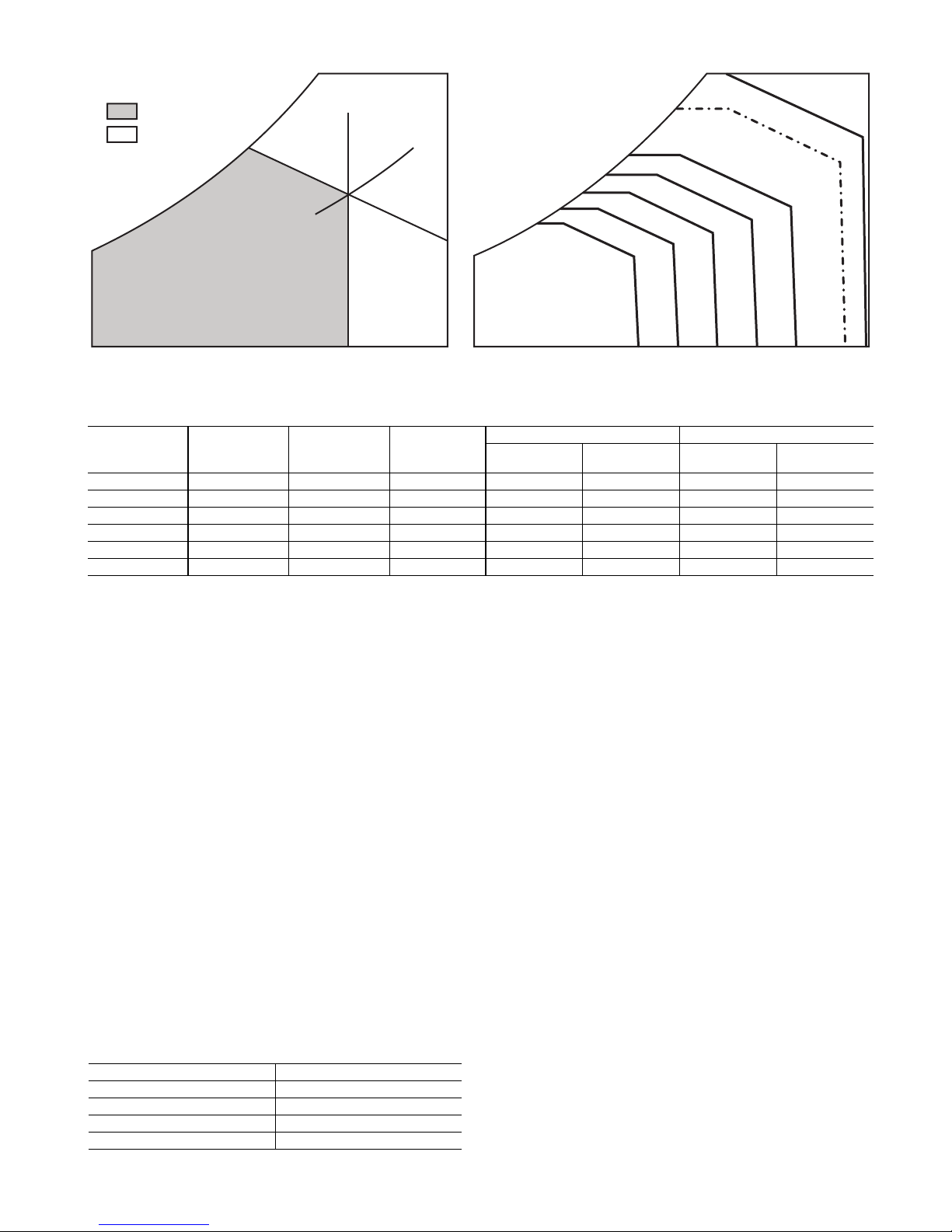
Fig. 40 — Single Enthalpy Curve Boundaries
ECONOMIZING
AVAILABLE
NOT AVAILABLE
ENTHA
LPY
RA HUM (%RH)
RA TEMP
TEMPERATURE
ABSOLUTE HUMIDITY
ES5
ES4
ES3
ES2 ES1
HL
P1
(T,RH)
P2 (T,RH)
SINGLE ENTHALPY
DUAL ENTHALPY
HIGH LIMIT
Table 19 — Single Enthalpy and Dual Enthalpy High Limit Curves
ENTHALPY
CURVE
ES1 80 60 28.0 80 36.8 66.3 80.1
ES2 75 57 26.0 75 39.6 63.3 80.0
ES3 70 54 24.0 70 42.3 59.7 81.4
ES4 65 51 22.0 65 44.8 55.7 84.2
ES5 60 48 20.0 60 46.9 51.3 88.5
HL 86 66 32.4 86 38.9 72.4 80.3
TEMP. DRY
BULB (F)
TEMP.
DEWPOINT (F)
ENTHALPY
(btu/lb/da)
TEMP. (F)
POINT P1 POINT P2
HUMIDITY
(%RH)
TEMP. (F)
HUMIDITY
(%RH)
ENTHALPY SETTINGS — When the OA temperature, enthalpy and dew point are below the respective setpoints, the
Outdoor Air can be used for economizing. Fig. 40 shows the
new single enthalpy boundaries in the W7220. There are 5
boundaries (setpoints ES1 through ES5), which are defined by
dry bulb temperature, enthalpy and dew point.
Refer to Table 19 for ENTH CURVE setpoint values.
The W7220 calculates the enthalpy and dew point using the
OA temperature and humidity input from the OA enthalpy sensor. When the OA temperature, OA humidity and OA dew
point are all below the selected boundary, the economizer sets
the economizing mode to YES, economizing is available.
When all of the OA conditions are above the selected
boundary, the conditions are not good to economize and the
mode is set to NO.
Fig. 40 shows the 5 current boundaries. There is also a high
limit boundary for differential enthalpy. The high limit boundary is ES1 when there are no stages of mechanical cooling energized and HL (high limit) when a compressor stage is energized.
Table 19 provides the values for each boundary limit.
TWO-SPEED FAN OPERATION — The W7220 controller has the capability to work with a system using a 2-speed
supply fan. The W7220 does not control the supply directly but
uses the following input status to determine the speed of the
supply fan and controls the OA damper to the required position, see Table 20.
Table 20 — Fan Speed
STATE FAN SPEED
OCC Low
Y1 Low
Y2 High
W High
The W (heating mode) is not controlled by the W7220 but it
requires the status to know where to position the OA damper
for minimum position for the fan speed.
The 2 speed fan delay is available when the system is programmed for 2 speed fan (in the System Setup menu item). The
2 speed fan delay is defaulted to 5 minutes and can be changed
in the Advanced Setup menu item. When the unit has a call for
Y1 In and in the free cooling mode and there is a call for Y2 In,
the 2-speed fan delay starts and the OA damper will modulate
100% open, the supply fan should be set to high speed by the
unit controller.
After the delay one of two actions will happen:
• The Y2 In call will be satisfied with the damper 100%
open and fan on high speed and the call will turn off.
OR
• If the call for additional cooling in the space has not been
satisfied then the first stage of mechanical cooling will
be enabled through Y1 Out or Y2 Out.
CHECKOUT — Inspect all wiring connections at the economizer module’s terminals, and verify compliance with the installation wiring diagrams.
For checkout, review the Status of each configured parameter and perform the Checkout tests.
NOTE: For information about menu navigation and use of the
keypad see Interface Overview on page 23.
33
Page 34
WARNING
Failure to follow this warning could result in personal
injury, property damage, or death.
Before performing service or maintenance operations on
unit, always turn off main power switch to unit and install
lock(s) and lockout tag(s). Unit may have more than one
power switch. Ensure electrical service to rooftop unit
agrees with voltage an amperage listed on the unit rating
plate.
If any wiring changes are required, first be sure to remove power from the Economizer module before starting
work. Pay particular attention to verifying the power connection (24 Vac).
Power Up
apply power.
Initial Menu Display
plays on the first line and economizer W7220 on the second
line. After a brief pause, the revision of the software appears on
the first line and the second line will be blank.
Power Loss (Outage or Brownout)
vanced settings are restored after any power loss or interruption.
NOTE: All settings are stored in non-volatile flash memory.
Status
rameter values for the various devices and sensors configured.
NOTE: For information about menu navigation and use of the
keypad see Interface Overview on page 23.
Checkout Tests
test the damper operation and any configured outputs. Only
items that are configured are shown in the Checkout menu.
the keypad see Interface Overview on page 23.
1. Scroll to the desired test in the Checkout menu using
2. Press the button to select the item. RUN? appears.
3. Press the button to start the test. The unit pauses and
— After the W7220 module is mounted and wired,
— On initial start up, Honeywell dis-
— All setpoints and ad-
— Use the Status menu (see Table 9) to check the pa-
— Use the Checkout menu (on page 28) to
NOTE: For information about menu navigation and use of
To perform a Checkout test:
the ▲ and ▼ buttons.
then displays IN PROGRESS. When the test is complete,
DONE appears.
4. When all desired parameters have been tested, press the
(Menu Up) button to end the test.
The Checkout tests can all be performed at the time of installation or at any time during the operation of the system as a
test that the system is operable.
TROUBLESHOOTING
Alarms
— The economizer module provides alarm messages
that display on the 2-line LCD.
NOTE: Upon power up, the module waits 60 minutes before
checking for alarms. This allows time for all the configured
devices (e.g. sensors, actuator) to become operational. The
exception is the SAT sensor which will alarm immediately.
If one or more alarms are present and there has been no keypad activity for at least 5 minutes, the Alarms menu displays
and cycles through the active alarms.
It is possible to navigate to the Alarms menu at any time.
Clearing Alarms
the cause has been removed (e.g. replaced faulty sensor) the
alarm can be cleared from the display.
To clear an alarm, perform the following:
1. Navigate to the desired alarm.
2. Press the button. ERASE? displays.
3. Press the button. ALARM ERASED displays.
4. Press the (Menu up/Exit) button to complete the action and return to the previous menu.
NOTE: If the alarm still exists after it is cleared, it is redisplayed within 5 seconds.
— Once the alarm has been identified and
CAUTION
Failure to follow this caution may result in damage to
equipment. Be sure to allow enough time for compressor
start-up and shutdown between checkout tests so the compressor does not short-cycle.
Low Ambient Control (Factory Option) — If the unit
comes with Electro-Mechanical (EM) control, then no adjustment is necessary.
If the unit comes with RTU Open controller option, then refer to its installation control manual for details on adjusting
“Cooling Lock-Out” setting and configure for the specific job
requirements.
34
Page 35
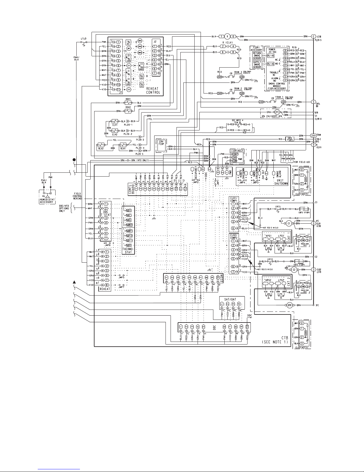
Fig. 41 — Typical Perfect Humidity™ Dehumidification System Humidistat Wiring
35
Page 36
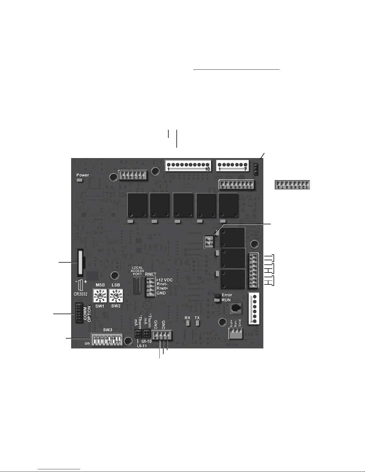
RTU Open Controller System — The RTU Open con-
J4
J2J1
J5 J5
J22
J17
J19
J14
J11
J22
J3
J13
J12
J15
J20
Network Comm
Configurable - Input_8
24 VAC
Configurable - Input_5
24 VAC
Configurable - Input_3
24 VAC
Input_9 (Humidistat)
24 VAC
24 VAC
Input _8 (Enthalpy)
AO-1 (ECON)
Gnd
(OAT)
Gnd
(SAT)
Input_5 (SMK)
Input_4 (R)
BO-5 (Y1)
BO-4 (Y2)
BO-3
(W1)
BO-2
(W2)
BO-1 (G)
Gnd
Input_3 (X)
24 VAC IN
+24 VDC
Input_2 (CO2/RH)
Gnd
+24 VDC
Input_1 (CO2/RH)
Gnd
Board Power
(AO-1)
0-10VDC
4-20mA
BO-6
(H) Humidimizer
BO-7
(Reversing Valve/High Speed Fan/Y3)
BO-8
(Power Exhaust)
LonWorks
Option Card
Port
Example set for
BACnet MS/TP
and 76.8K baud
(1, 2, and 4 ON)
Recommended for all
i-Vu Open installations
2N ro ,subdoM ,tenCAB)tupni pmet( TPSrotceleS locotorP
(LON connection J15)
SPT (common)
SPT (offset input)
*Remove
both for 0-5V
AO-2
GND
(2-10V)
3-Volt
Lithium
Battery
BO-1 BO-2 BO-3 BO-4 BO-5
BO-6
BO-7
BO-8
VFD Output
troller is factory-mounted in the 581J unit’s main control box,
to the left of the CTB (see Fig. 42). Factory wiring is completed through harnesses connected to the CTB. Field-connections
for RTU Open controller sensors will be made at the Phoenix
connectors on the RTU Open board. The factory-installed RTU
Open controller includes the supply-air temperature (SAT) sensor. The outdoor air temperature (OAT) sensor is included in
the FIOP/accessory EconoMi$er 2 package.
The RTU Open controller is an integrated component of the
Bryant rooftop unit. Its internal application programming
provides optimum performance and energy efficiency. RTU
Open enables the unit to run in 100% stand-alone control mode
or a Third Party Building Automation System (BAS). Onboard DIP switches allow to select your protocol (and baud
rate) of choice among the four most popular protocols in use
today: BACnet
1
, Modbus2, Johnson N2 and LonWorks3. (See
Fig. 42.)
Refer to Table 21, RTU Open Controller Inputs and Outputs
for locations of all connections to the RTU Open controller
board. See Fig. 43 and 44 for wiring diagrams.
1. BACnet is a registered trademark of ASHRAE (American
Society of Heating, Refrigerating and Air-Conditioning Engineers).
2. Modbus is a registered trademark of Schneider Electric.
3. LonWorks is a registered trademark of Echelon Corporation.
Fig. 42 — RTU Open Multi-Protocol Controller Board
36
Page 37

Fig. 43 — Typical RTU Open Controller Wiring Diagram
37
Page 38
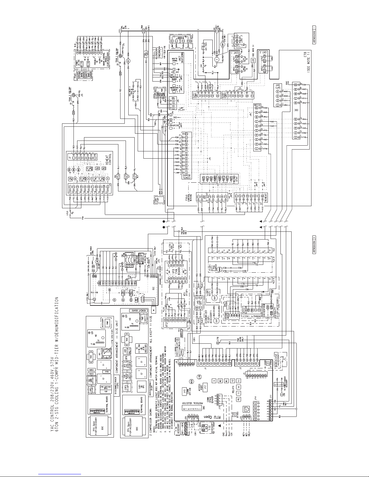
Fig. 44 — Typical RTU Open Controller Wiring Diagram with Perfect Humidity™ System Option
38
Page 39
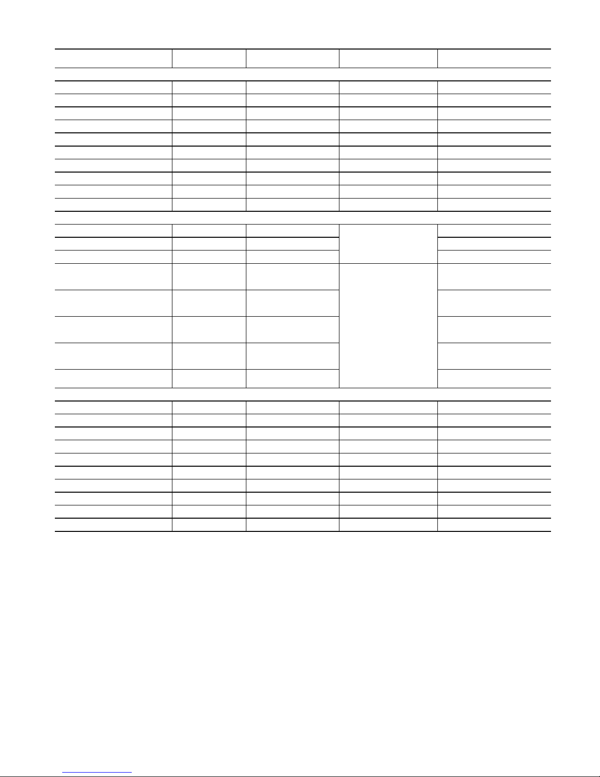
Table 21 — RTU Open Controller Inputs and Outputs
POINT NAME
BACNET OBJECT
NAME
TYPE OF I/O
DEDICATED INPUTS
Space Temp / Zone Temp
Supply Air Temperature
Outside Air Temperature
Space Temperature Offset Pot
Safety Chain Feedback
Compressor Safety Status
(1)
Fire Shutdown Status
Enthalpy Status
Humidistat Input Status
Zone Temperature
CONFIGURABLE INPUTS
Indoor Air CO
Outdoor Air CO
2
2
(4)
Space Relative Humidity
Supply Fan Status
Filter Status
Door Contact
Remote Occupancy input
IGC input
(2)
(2)
(2)
(2)
(2)
zone_temp AI (10K Thermistor) J20—1 & 2 Analog Input 10
sa_temp AI (10K Thermistor) J2—1 & 2 Analog Input 6
oa_temp AI (10K Thermistor) J2—3 & 4 Analog Input 7
stpt_adj_offset AI (100K Potentiometer) J20—3 & 4 Analog Input 11
safety_status BI (24 VAC) J1—9 Binary Input 4
comp_status BI (24 VAC) J1—2 Binary Input 3
firedown_status BI (24 VAC) J1—10 Binary Input 5
enthalpy_status BI (24 VAC) J2—6 & 7 Binary Input 8
humstat_status BI (24 VAC) J5—7 & 8 Binary Input 9
N/A N/A J13—1—4 Rnet
iaq AI (4-20 mA)
oaq AI (4-20 mA) Analog Input 1
space_rh AI (4-20 mA) Analog Input 10
sfan_status BI (24 VAC)
filter_status BI (24 VAC)
door_contact_sta-
tus
BI (24 VAC)
occ_contact_status BI (24 VAC)
igcovr_status BI (24 VAC)
OUTPUTS
Economizer Output
Supply Fan VFD
Supply Fan Relay
Cool 1 Relay State
Cool 2 Relay State
Cool 3 Relay State
Heat 1 Relay State
Heat 2 Relay State
Power Exhaust Relay State
Dehumidification Relay
econ_output AO (4-0mA) J2—5 Analog Output 1
vfd_output AO (2-10Vdc) J22—1 & 2 Analog Output 2
sfan BO Relay (24VAC, 1A) J1—4 Binary Output 1 (G)
comp_1 BO Relay (24VAC, 1A) J1—8 Binary Output 5 (Y1)
comp_2 BO Relay (24VAC, 1A) J1— 7 Binary Output 4 (Y2)
comp_3 BO Relay (24VAC, 1A) J11—5 & 6 Binary Output 7 (Y3)
heat_1 BO Relay (24VAC, 1A) J1—6 Binary Output 3 (W1)
heat_2 BO Relay (24VAC, 1A) J1—5 Binary Output 2 (W2)
pexh BO Relay (24VAC, 1A) J11—2 & 3 (N.O.) Binary Output 8 (PE)
dehum BO Relay (24VAC, 1A) J11—7 & 8 (N.O.) Binary Output 6
LEGEND
AI — Analog Input
AO — Analog Output
BI — Binary Input
BO — Binary Output
1. Safety Chain Feedback: 24Vac required at this terminal to provide “Run Enable” status. See Input/Output section for additional instructions.
CONNECTION PIN
NUMBER(S)
CHANNEL DESIGNATION
Analog Input 2
J4—2 & 3 or J4—5 & 6
Binary Input 3, 5, 8, or 9,
except where intrinsic input is
used
Binary Input 3, 5, 8, or 9,
except where intrinsic input is
used
J5—1 & 2 or J5—3 & 4,
J5—5 & 6 or J5—7 & 8
Binary Input 3, 5, 8, or 9,
(3)
except where intrinsic input is
used
Binary Input 3, 5, 8, or 9,
except where intrinsic input is
used
Binary Input 9. Mandatory
input on gas heat units.
2. These inputs are configurable. If installed, they take the place
of the default input on the specific channel. See appropriate
Input Configuration Section for wiring and setup instructions.
3. Parallel pins J5—1 = J2—6, J5—3 = J1—10, J5—5 = J1—2 are
used for field installation.
4. Refer to the input configuration and accessory sections of the
RTU Open Multi-Protocol Controller Controls, Start-Up, Operation and Troubleshooting manual for more detail.
39
Page 40
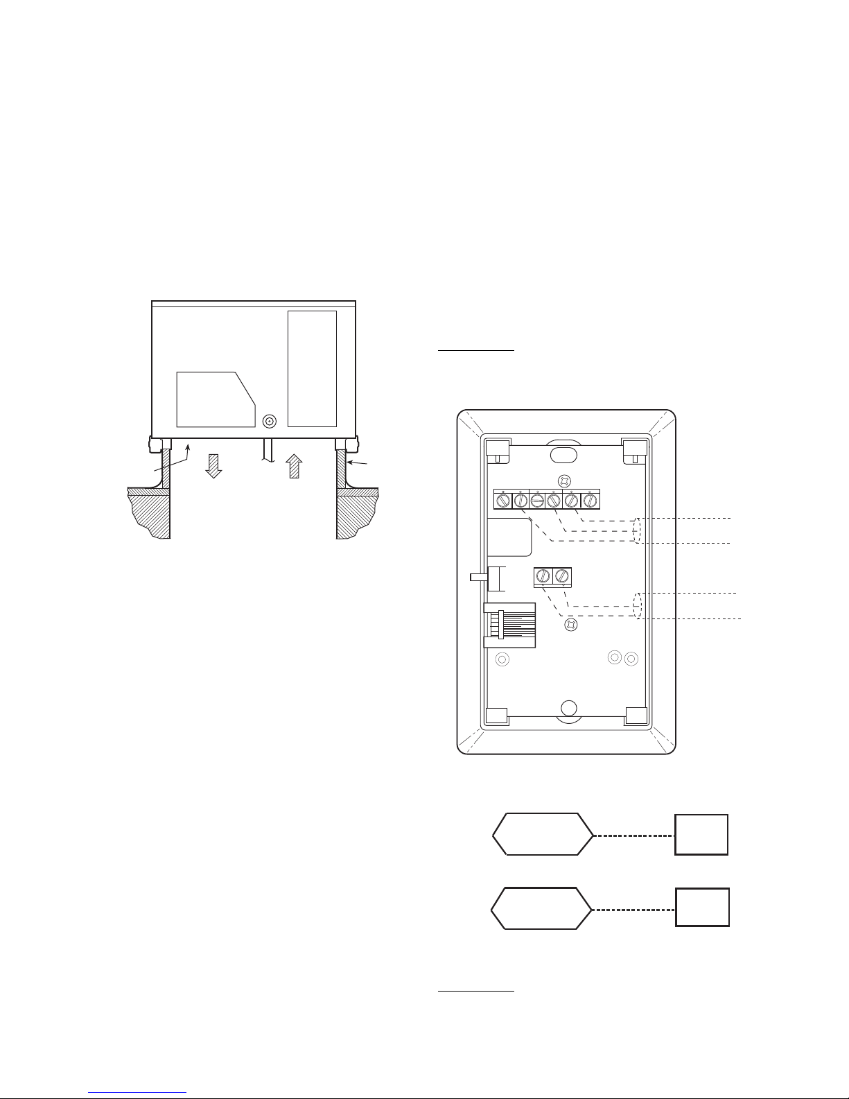
The RTU Open controller requires the use of a Bryant space
2
3
45
61
SW1
SEN
BRN (GND)
BLU (SPT)
RED(+)
WHT(GND)
BLK(-)
CCN COM
SENSOR WIRING
sensor. A standard thermostat cannot be used with the RTU
Open system.
SUPPLY AIR TEMPERATURE (SAT) SENSOR — On
FIOP-equipped 581J unit, the unit is supplied with a supply-air
temperature (SAT) sensor (33ZCSENSAT). This sensor is a tubular probe type, approx 6-inches (152 mm) in length. It is a
nominal 10k ohm thermistor.
The SAT is factory-wired. The SAT probe is wire-tied to the
supply-air opening (on the horizontal opening end) in its shipping position. Remove the sensor for installation. Re-position
the sensor in the flange of the supply-air opening or in the supply air duct (as required by local codes). Drill or punch a
1
/2-in. hole in the flange or duct. Use two field-supplied, selfdrilling screws to secure the sensor probe in a horizontal orientation. See Fig. 45.
has a variety of options consisting of: timed override button, set
point adjustment, a LCD screen, and communication tie in.
Space temperature can be also be written to from a building
network or zoning system. However, it is still recommended
that return air duct sensor be installed to allow stand-alone operation for back-up. Refer to the configuration section for details on controller configurations associated with space sensors.
• 33ZCT55SPT, space temperature sensor with override
button (T-55)
• 33ZCT56SPT, space temperature sensor with override
button and setpoint adjustment (T-56)
• 33ZCT59SPT, space temperature sensor with LCD (liquid crystal display) screen, override button, and setpoint
adjustment (T-59)
Use 20 gauge wire to connect the sensor to the controller.
The wire is suitable for distances of up to 500 ft. Use a threeconductor shielded cable for the sensor and setpoint adjustment
connections. If the setpoint adjustment (slidebar) is not required, then an unshielded, 18 or 20 gauge, two-conductor,
twisted pair cable may be used.
Connect T-55
— See Fig. 46 for typical T-55 internal connections. Connect the T-55 SEN terminals to the RTU Open controller at J20-1 and J20-2. See Fig. 47.
SUPPLY AIR
TEMPERATURE
SENSOR
SUPPLY AIR
RETURN AIR
Fig. 45 — Typical Mounting Location for Supply Air
Temperature (SAT) Sensor on Small Rooftop Units
OUTDOOR AIR TEMPERATURE (OAT) SENSOR —
The OAT is factory-mounted in the EconoMi$er
®
2 (FIOP or
accessory). It is a nominal 10k ohm thermistor attached to an
eyelet mounting ring.
ECONOMI$ER 2 — The RTU Open controller is used with
EconoMi$er 2 (factory-installed option or field-installed accessory) for outdoor air management. The damper position is controlled directly by the RTU Open controller; EconoMi$er 2 has
no internal logic device.
Outdoor air management functions can be enhanced with
field-installation of these accessory control devices:
Enthalpy control (outdoor air or differential sensors)
Space CO
Outdoor air CO
sensor
2
sensor
2
Field Connections — Field connections for accessory sen-
sors and input devices are made the RTU Open controller, at
plugs J1, J2, J4, J5, J11 and J20. All field control wiring that
connects to the RTU Open controller must be routed through
the raceway built into the corner post as shown in Fig. 31. The
raceway provides the UL required clearance between high and
low-voltage wiring. Pass the control wires through the hole
provided in the corner post, then feed the wires through the
raceway to the RTU Open controller. Connect to the wires to
the removable Phoenix connectors and then reconnect the connectors to the board.
SPACE TEMPERATURE (SPT) SENSORS — There
are two types of SPT sensors available from Bryant, resistive
input non-communicating (T55, T56, and T59) and Rnet communicating (SPS, SPPL, SPP, and SPPF) sensors. Each type
ROOF
CURB
Fig. 46 — T-55 Space Temperature Sensor Wiring
SEN
SEN
J20-1
J20-2
Fig. 47 — RTU Open Controller T-55 Sensor
Connections
Connect T-56
— See Fig. 50 for T-56 internal connections. Install a jumper between SEN and SET terminals as illustrated.
Connect T-56 terminals to the RTU Open controller at J20
J20
—2 and J20—3 per Fig. 49.
—1,
40
Page 41
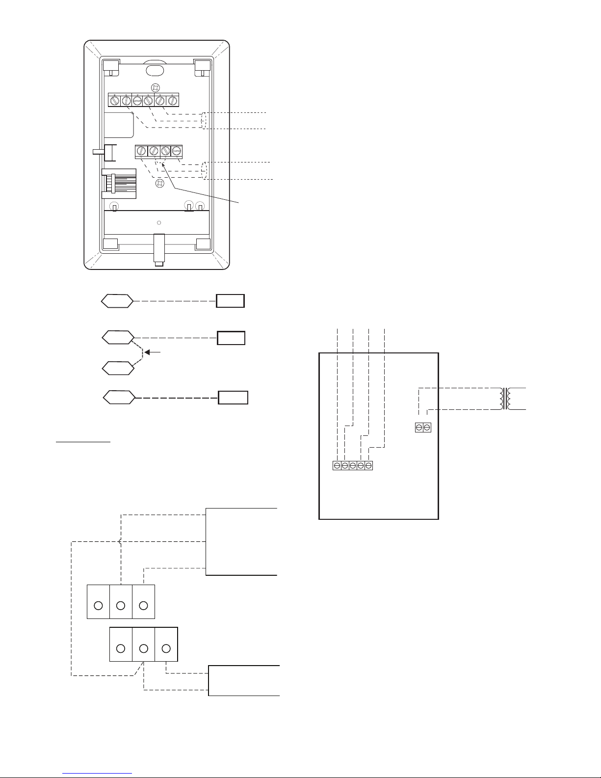
SEN J20-1
J20-2
SEN
SET
Jumper
J20-3
SET
OR SET SEN
OPB COM- PWR+
BLU (SPT)
BLK (STO)
24 VAC
SENSOR
WIRING
POWER
WIRING
BRN (COM)
NOTE: Must use a separate isolated transformer.
J20-3
J20-2
J20-1
To controller
24 Vac Line
Dedicated Transformer
+
-
24 Vac
or Vdc
8 7 6 5 4
2 1
SENSOR LEGEND
1 +24 Vac/Vdc
2 Gnd (-24 Vac/Vdc)
4 -Thermistor
5 +Thermistor
6 4-20 mA
7 SIG COM
8 0-5 Vdc
INDOOR AIR QUALITY (CO
) SENSOR — The in-
2
door air quality sensor accessory monitors space carbon dioxide (CO
) levels. This information is used to monitor IAQ lev-
2
els. Several types of sensors are available, for wall mounting in
the space or in return duct, with and without LCD display, and
in combination with space temperature sensors. Sensors use infrared technology to measure the levels of CO
2
3
SW1
45
SEN
61
RED(+)
WHT(GND)
BLK(-)
SET
BLK
(T56)
BRN (GND)
BLU (SPT)
CCN COM
SENSOR WIRING
JUMPER
TERMINALS
AS SHOWN
space air.
The CO
sensors are all factory set for a range of 0 to 2000
2
ppm and a linear mA output of 4 to 20. Refer to the instructions
supplied with the CO
sensor for electrical requirements and
2
terminal locations. See Fig. 51 for typical CO
schematic.
To accurately monitor the quality of the air in the conditioned air space, locate the sensor near a return-air grille (if
present) so it senses the concentration of CO
The sensor should be mounted in a location to avoid direct
breath contact.
present in the
2
sensor wiring
2
leaving the space.
2
Do not mount the IAQ sensor in drafty areas such as near
supply ducts, open windows, fans, or over heat sources. Allow
at least 3 ft (0.9 m) between the sensor and any corner. Avoid
mounting the sensor where it is influenced by the supply air;
Cool Warm
the sensor gives inaccurate readings if the supply air is blown
directly onto the sensor or if the supply air does not have a
Fig. 48 — T-56 Internal Connections
chance to mix with the room air before it is drawn into the return airstream.
Fig. 49 — RTU Open Controller T-56 Sensor
Connections
Connect T-59
— The T-59 space sensor requires a separate,
isolated power supply of 24 VAC. See Fig. 50 for internal connections at the T-59. Connect the SEN terminal (BLU) to the
RTU Open controller at J20
(BRN) to J20
J20—3.
Fig. 50 — Space Temperature Sensor Typical Wiring
—2. Connect the SET terminal (STO or BLK) to
—1. Connect the COM terminal
(33ZCT59SPT)
Fig. 51 — Indoor/Outdoor Air Quality (CO
) Sensor
2
(33ZCSPTCO2-01 or 33ZCSPTCO2LCD-01) Typical
Wiring Diagram
Wiring the Indoor Air Quality Sensor: For each sensor, use
two 2-conductor 18 AWG (American Wire Gage) twisted-pair
cables (unshielded) to connect the separate isolated 24 vac
power source to the sensor and to connect the sensor to the control board terminals.
To connect the sensor to the control, identify the positive (4
to 20 mA) and ground (SIG COM) terminals on the sensor. See
Fig. 51. Connect the 4-20 mA terminal to the RTU Open controller at J4-2 and connect the SIG COM terminal to the RTU
Open controller at J4-3. See Fig. 52.
41
Page 42
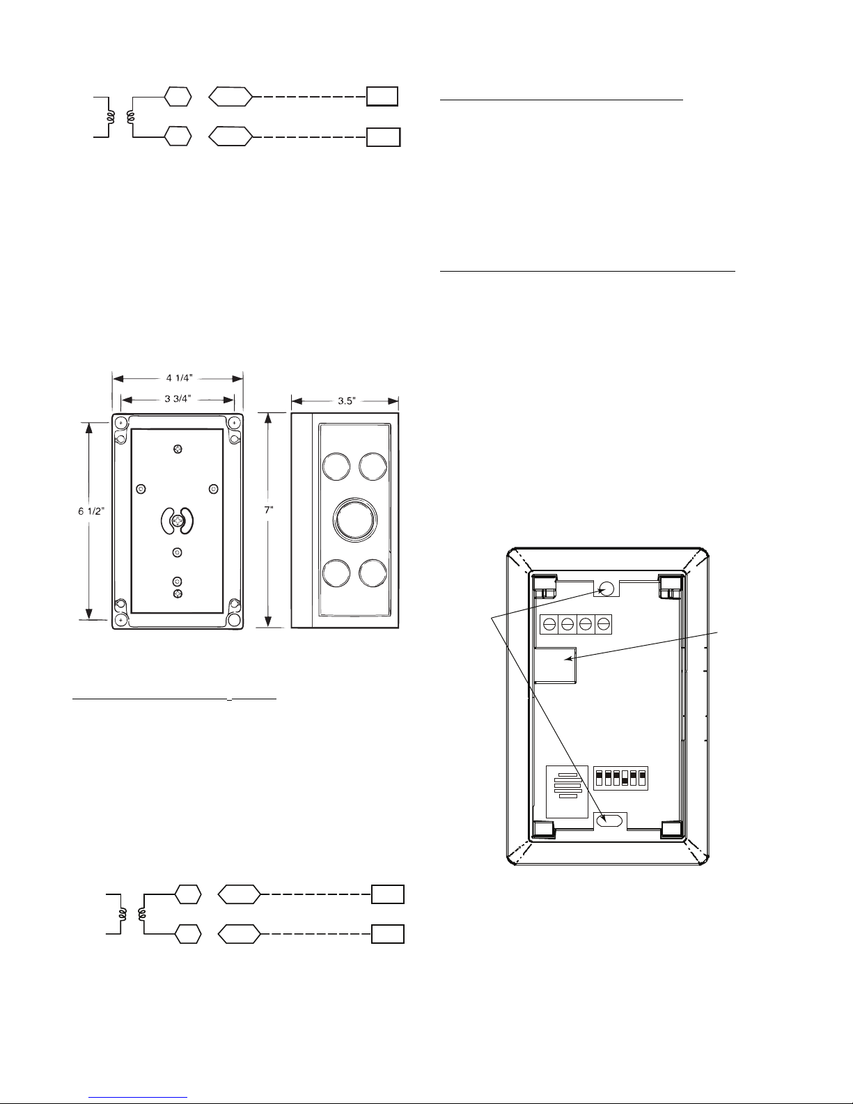
SEN
COM
J4-2
J4-3
IAQ Sensor
24 VAC
SEN
COM
J4-5
J4-6
OAQ Sensor
24 VAC
SPACE RELATIVE HUMIDITY SENSOR OR
HUMIDISTAT
Fig. 52 — RTU Open Controller/Indoor CO2 Sensor
(33ZCSPTCO2-01 or 33ZCSPTCO2LCD-01)
Connections
OUTDOOR AIR QUALITY SENSOR (P/N 33ZCSPTCO2-01 OR 33ZCSPTCO2LCD-01 PLUS WEATHERPROOF ENCLOSURE) — The outdoor air CO
sensor is
2
designed to monitor carbon dioxide (CO2) levels in the outside
ventilation air and interface with the ventilation damper in an
HVAC system.
The OAQ sensor is packaged with an outdoor cover. See
Fig. 53. The outdoor air CO
sensor must be located in the
2
economizer outside air hood.
Perfect Humidity™ System Control Wiring
— In units
equipped with the Perfect Humidity option there are two loose
wires loose in the control box (one PNK and one PNK/BLK)
used to control the dehumidification function of the unit. These
wires are meant to be tied to a space humidistat or thermidistat
on an electromechanical unit. On RTU Open controller
equipped units these wires must be connected to J11
—7 and 8
to allow the Open board to operate the dehumidification function for the unit. Disconnect the J11 Phoenix style connector
from the board and use the plug screws to secure the wires as
follows: secure the PNK/BLK wires at pin 7 and the PNK
wires at pin 8, and then reconnect the plug to the board at J11.
Relative Humidity Sensors (Space or Duct Mounted)
— The
accessory space humidity sensor (33ZCSENSRH-01) or duct
humidity sensor (33ZCSENDRH-01) is used to measure the
relative humidity of air within the space or return air duct. The
RH reading is used to control the Perfect Humidity option of
the rooftop unit. For wiring distances up to 500 ft (152 m), use
a 3-conductor, 18 or 20 AWG shielded cable. The shield must
be removed from the sensor end of the cable and grounded at
the unit end. The current loop power for sensor is provided by
the RTU Open controller as 24vdc. Refer to the instructions
supplied with the RH sensor for the electrical requirements and
terminal locations. RTU Open controller configurations must
be changed after adding an RH sensor. See Fig. 55 and 56 for
typical RH sensor wiring.
•J4
—1 or J4—4 = 24vdc loop power
•J4
—2 or J4—5 = 4-20mA signal input
NOTE: The factory default for dehumidification control is normally open humidistat.
COVER REMOVED SIDE VIEW
Fig. 53 — Outdoor Air Quality Sensor Cover
Wiring the Outdoor Air CO
Sensor — A dedicated power
2
supply is required for this sensor. A two-wire cable is required
to wire the dedicated power supply for the sensor. The two
wires should be connected to the power supply and terminals 1
and 2.
To connect the sensor to the control, identify the positive (4
to 20 mA) and ground (SIG COM) terminals on the OAQ sensor. See Fig. 51. Connect the 4 to 20 mA terminal to the RTU
Open controller at J4
the RTU Open controller at J4
—5. Connect the SIG COM terminal to
—6. See Fig. 54.
Fig. 54 — RTU Open Controller/Outdoor CO
Sensor
2
(33ZCSPTCO2-01 or 33ZCSPTCO2LCD-01)
Connections
MOUNTING
HOLES
Io
Gnd
Vin
Vo
SW2
123456
ON
Vin - J4-1 or J4-4 24Vdc
Io - J4-2 or J4-5 -20mA output
WIRING
OPENING
Fig. 55 — Space Relative Humidity Sensor Typical
Wiring
42
Page 43

SPAN
ZERO
4-20mAVAC
or
VDC
GND 0-5V
or
0-10V
123456
ON
J4-1 or J4-4 + 24 VDC
SUPPLY VOLTAGE
J4-2 or J4-5 (-)4 to 20 mA Current
LOOP OUTPUT TO RTU OPEN
RELATIVE HUMIDITY SENSOR
(POLARIZED MALE CONNECTOR)
Fig. 56 — Duct Relative Humidity Sensor Typical
Wiring
Humidistat
— The accessory humidistat provides the RTU
Open controller insight to the relative humidity in the space.
The humidistat reads the RH level in the space and compares it
to its setpoint to operate a dry contact. The humidistat is a
dedicated input on the configurable input 9 and tells the RTU
Open controller when the RH level is HIGH or LOW. The
normal condition for humidity is LOW. A normally open
humidistat is the factory default control for the Perfect
Humidity system option.
To wire in the field:
•J5
—8 = 24 VAC source for dry contact
•J5
—7 = Signal input
SMOKE DETECTOR/FIRE SHUTDOWN (FSD) —
On 581J units equipped with factory-installed Smoke Detector(s), the smoke detector controller implements the unit shutdown through its NC contact set connected to the unit’s CTB
input. The FSD function is initiated via the smoke detector’s
Alarm NO contact set. The RTU Open controller communicates the smoke detector’s tripped status to the BAS building
control. See Fig. 43 and 44, (RTU Open Controller wiring diagrams).
The Fire Shutdown Switch configuration, MENU
fig
Inputsinput 5, identifies the normally open status of
Con-
this input when there is no fire alarm.
Connecting Discrete Inputs
Filter Status
— The filter status accessory is a field-installed
accessory. This accessory detects plugged filters. When installing this accessory, the unit must be configured for filter status
by setting MENU
ConfigInputsinput 3, 5, 8, or 9 to
Filter Status and normally open (N/O) or normally closed
(N/C). Input 8 or 9 is recommended for ease of installation. Refer to Fig. 42 and Fig. 43 or 44 for wire terminations at J5.
Fan Status
— The fan status accessory is a field-installed accessory. This accessory detects when the indoor fan is blowing
air. When installing this accessory, the unit must be configured
for fan status by setting MENU
ConfigInputsinput 3,
5, 8, or 9 to Fan Status and normally open (N/O) or normally
closed (N/C). Input 8 or 9 is recommended for easy of installation. Refer to Fig. 42 and Fig. 43 or 44 for wire terminations at
J5.
Remote Occupancy
— The remote occupancy accessory is a
field-installed accessory. This accessory overrides the unoccupied mode and puts the unit in occupied mode. When installing
this accessory, the unit must be configured for remote occupancy by setting MENU
ConfigInputsinput 3, 5, 8, or 9 to
Remote Occupancy and normally open (N/O) or normally
closed (N/C).
Also set MENU
Schedulesoccupancy source to DI on/
off. Input 8 or 9 is recommended for ease of installation. Refer
to Fig. 42 and Table 21 for wire terminations at J5.
Power Exhaust (output)
— The relay used by the RTU Open
controller board to control power exhaust is a dry contact
which means it does not have 24vac. This 24vac must be connected to the relay to allow it to operate the power exhaust relay in the PE accessory. A 24vac source must be provided to
J11
—2 on the RTU Open controller board. This can be provid-
ed by the unit’s transformer from various sources. The “R” terminal on the unit’s central terminal board (CTB) is a logical
source. Refer to Fig. 42 and Fig. 43 or 44 for wire terminations
at J11.
Communication Wiring — Protocols
GENERAL — Protocols are the communication languages
spoken by control devices. The main purpose of a protocol is to
communicate information in the most efficient method possible. Different protocols exist to provide different kinds of information for different applications. In the BAS application, many
different protocols are used, depending on manufacturer. Protocols do not change the function of a controller; just make the
front end user different.
The RTU Open controller can be set to communicate on
four different protocols: BACnet, Modbus, N2, and LonWorks.
Switch 3 (SW3) on the board is used to set protocol and baud
rate. Switches 1 and 2 (SW1 and SW2) are used to set the
board’s network address. See Fig. 57 and 58 for protocol
switch settings and address switches. The third party connection to the RTU Open controller is through plug J19. See
Fig. 59 for wiring.
NOTE: Power must be cycled after changing the SW1
switch settings.
Refer to the RTU Open Controller Integration Guide for
more detailed information on protocols, third party wiring, and
networking.
—3
43
Page 44
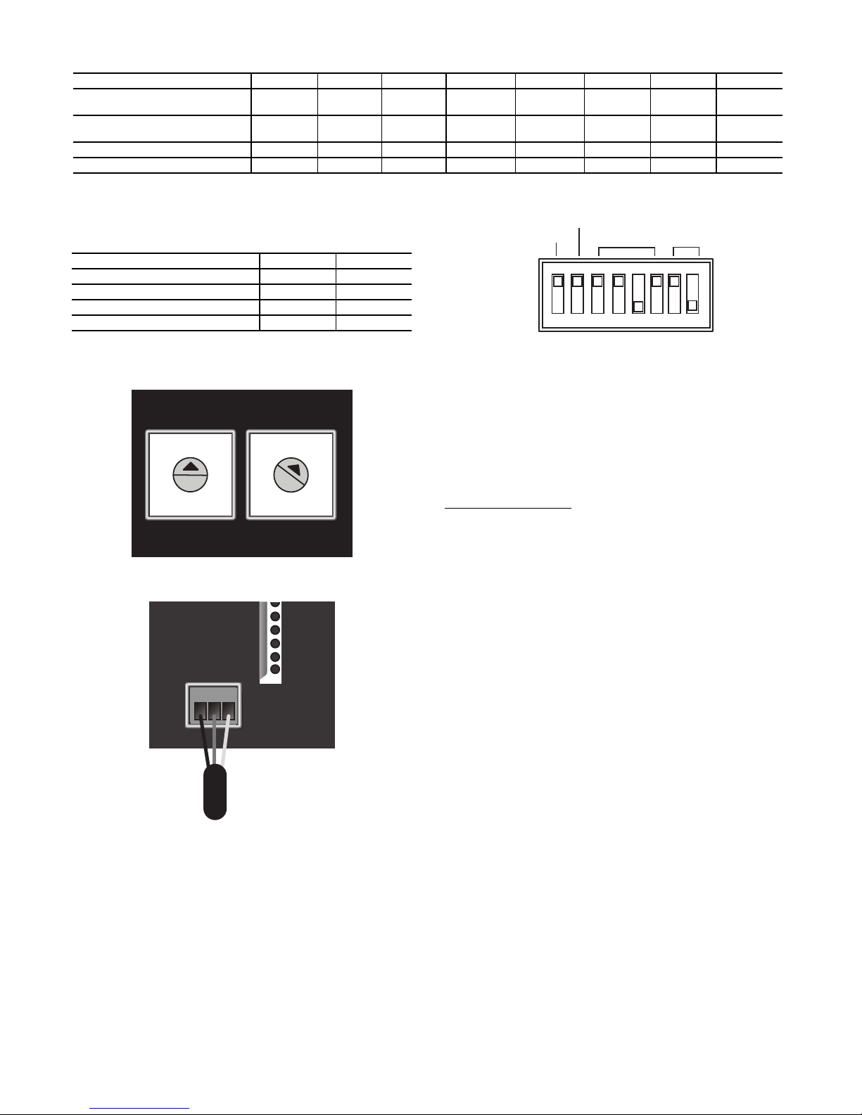
SW3 Protocol Selection
UNUSED
(OFF)
(ON)
COMM
OPTION
PORT
SET TO MSTP
(MASTER)
SET TO
38.4k
BAUD
PROTOCOL SELECTOR DIP SWITCHES
PROTOCOL DS8 DS7 DS6 DS5 DS4 DS3 DS2 DS1
BACnet MS/TP (Master) Unused OFF OFF OFF ON OFF
Modbus (Slave) Unused OFF OFF ON ON OFF
N2 (Slave) Unused OFF OFF OFF ON ON OFF OFF
LonWorks Unused ON ON OFF ON OFF OFF ON
LEGEND
DS – Dip Switch
NOTE: BACnet MS/TP SW3 example shown
Select
Baud
Select
Baud
Select
Baud
Select
Baud
Baud Rate Selections
BAUD RATE DS2 DS1
9,600 OFF OFF
19,200 ON OFF
38,400 OFF ON
76,800 ON ON
Fig. 57 — RTU Open Controller SW3 Dip Switch Settings
FIELD ASSISTANT — Field Assistant is a computer pro-
gram included with the purchase of the Tech Tool Kit (USB-
MSB LSB
TKIT). This is a field Tech Tool to set-up, service, or download
application software to the RTU Open controller and includes a
0
1
9
8
7
2
3
4
6
5
0
1
9
8
7
2
3
4
6
5
USB Link Cable. The link cable connects a USB port to the
J12 local access port. See Fig. 60.
RTU OPEN CONTROLLER TROUBLESHOOTING
Communication LEDs
— The LEDs indicate if the controller
is speaking to the devices on the network. The LEDs should reflect communication traffic based on the baud rate set. The
SW1 SW2
higher the baud rate the more solid the LEDs will appear. See
Table 22.
Fig. 58 — RTU Open Controller Address Switches
NOTE: Refer to the RTU Open Multi-Protocol Controller
Controls, Start-Up, Operation and Troubleshooting manual for
complete configuration of the RTU Open controller, operating
sequences and troubleshooting information. Refer to the RTU
Open v3 Integration Guide for details on configuration and
troubleshooting of connected networks. Have a copy of these
manuals available at unit start-up.
NET+
NET-
SHLD
J19
Fig. 59 — Network Wiring
Local Access
WALL MOUNTED EQUIPMENT TOUCH INTERFACE — The Equipment Touch™ interface is a wall mount-
ed interface used to connect to the RTU Open controller to access the control information, read sensor values, and maintenance. This is an accessory interface that does not come with
the RTU Open controller. Wire the Equipment Touch interface
to the RTU Open controller’s J13 local access port. There are 2
password protected levels in the display (User and Admin). See
the Equipment Touch Installation and Setup Guide for more information. See Appendix A for navigation and screen content.
44
Page 45

Connect to
computer’s
USB port
Connect to
the Local
Access port
USB Link Kit
RTU Open Controller
Access
Port
J12
P1 P1
P5 P5
LOCAL
ACCESS
PORT
GND
GND
*Therm
mA
*Therm
mA
UI-10
UI-11
SW3
on
COMM
OPTION
CR2032
+
-
SW1 SW2
MSB LSB
TXRX
+12 DVC
RnetRnet+
GND
RNET
J12
J13
J15
J20
The LEDs on the RTU Open Controller show the status of certain functions
If this LED is on... Status is...
Power
Rx
Tx
BO#
The RTU Open controller has power
The RTU Open controller is receiving data from the network segment
The RTU Open controller is transmitting data over the network segment
The binary output is active
The Run and Error LEDs indicate control module and network status
If Run LED shows...
2 flashes per second
2 flashes per second
2 flashes per second
2 flashes per second
2 flashes per second
5 flashes per second
5 flashes per second
7 flashes per second
14 flashes per second
On
Off Normal
2 flashes, alternating with Run LED Five minute auto-restart delay after system error
3 flashes, then off Control module has just been formatted
4 flashes, then pause
On
On Exec start-up aborted, Boot is running
Off Firmware transfer in progress, Boot is running
7 flashes per second, alternating with Run LED Ten second recovery period after brownout
14 flashes per second, alternating with Run
LED
On
Outdoor Air Enthalpy Control (P/N
33CSENTHSW) —
(33CSENTHSW) is available as a field-installed accessory to
be used with the EconoMi$er
air enthalpy sensor is part of the enthalpy control. (The separate
field-installed accessory return air enthalpy sensor (33CSENTSEN) is required for differential enthalpy control. See Fig. 61.)
Locate the enthalpy control in the economizer next to the
Actuator Motor. Locate two GRA leads in the factory harness
and connect the gray lead labeled “ESL” to the terminal labeled
“LOW.” See Fig. 61. Connect the enthalpy control power input
terminals to economizer actuator power leads RED (connect to
24V) and BLK (connect to GND).
The outdoor enthalpy changeover setpoint is set at the enthalpy controller.
The enthalpy control
®
2 damper system. The outdoor
Fig. 60 — PC Running Field Assistant
Table 22 — LEDs
And Error LED shows... Status is...
Two or more devices on this network have the same
MSTP network address
Exec halted after frequent system errors or control programs halted
Brownout
Failure. Try the following solutions:
· Turn the RTU Open controller off, then on.
· Format the RTU Open controller.
· Download memory to the RTU Open controller.
· Replace the RTU Open controller.
Enthalpy
Switch
45
Fig. 61 — Enthalpy Switch (33CSENTHSW)
24V
GND
LOW
RED
BLK
GRA
FACTORY WIRING HARNESS
Connections
PL6-1 (24-V)
PL6-4 (COM)
CTB ECON
7
(P’LINK: to J4-2) or
(RTU Open: to J2-6)
Page 46

DIFFERENTIAL ENTHALPY CONTROL — Differen-
GRA
BLK
RED
– 4-20
MAIN
+ VDC
OUT
– 4-20 MAIN
OUT
+ 24-36
VDC IN
LOW
GND
24V
7
PL6-1 (24-V)
PL6-4 (COM)
OUTSIDE AIR
ENTHALPY SWITCH
RETURN AIR
ENTHALPY
SENSOR
CTB ECON
(P’LINK: to J4-2) or
(RTU Open: to J2-6)
RETURN AIR
SMOKE DETECTOR
(AS SHIPPED)
STEP 1 STEP 2 STEP 3
tial enthalpy control is provided by sensing and comparing the
outside air and return air enthalpy conditions. Install the outdoor air enthalpy control as described above. Add and install a
return air enthalpy sensor.
RETURN AIR ENTHALPY SENSOR — Mount the return-air enthalpy sensor (33CSENTSEN) in the return-air section of the economizer. The return air sensor is wired to the enthalpy controller (33CSENTHSW). See Fig. 62.
Fig. 62 — Outside and Return Air Enthalpy Sensor
Wiring
To wire the return air enthalpy sensor, perform the follow-
ing:
1. Use a 2-conductor, 18 or 20 AWG, twisted pair cable to
connect the return air enthalpy sensor to the enthalpy controller.
2. Connect the field-supplied RED wire to (+) spade connector on the return air enthalpy sensor and the (+) terminal on the enthalpy controller. Connect the BLK wire to
(–) spade connector on the return air enthalpy sensor and
the (
–) terminal on the enthalpy controller.
Smoke Detectors — Smoke detectors are available as fac-
tory-installed options on 581J models. Smoke detectors may be
specified for Supply Air only or for Return Air without or with
economizer or in combination of Supply Air and Return Air.
All components necessary for operation are factory-provided
and mounted. The unit is factory-configured for immediate
smoke detector shutdown operation; additional wiring or modifications to unit terminal board may be necessary to complete
the unit and smoke detector configuration to meet project requirements.
Units equipped with factory-optional Return Air smoke detectors require a relocation of the sensor module at unit installation. See Fig. 63 for the as shipped location.
Completing Installation of Return Air Smoke Sensor:
1. Unscrew the two screws holding the Return Air Smoke
Detector assembly. See Fig. 64, Step 1. Save the screws.
2. Turn the assembly 90 and then rotate end to end. Make
sure that the elbow fitting is pointing down. See Fig. 64,
Step 2.
3. Screw the sensor and detector plate into its operating position using screws from Step 1. See Fig. 64, Step 3.
4. Connect the flexible tube on the sampling inlet to the
sampling tube on the basepan.
Fig. 63 — Return Air Smoke Detector, Shipping
Position
ADDITIONAL APPLICATION DATA — Refer to the
Application Data sheet titled Factory Installed Smoke Detectors for Small and Medium Rooftop Units 2 to 25 Tons for discussions on additional control features of these smoke detectors including multiple unit coordination.
Fig. 64 — Completing Installation of Return Air Smoke Sensor
46
Page 47
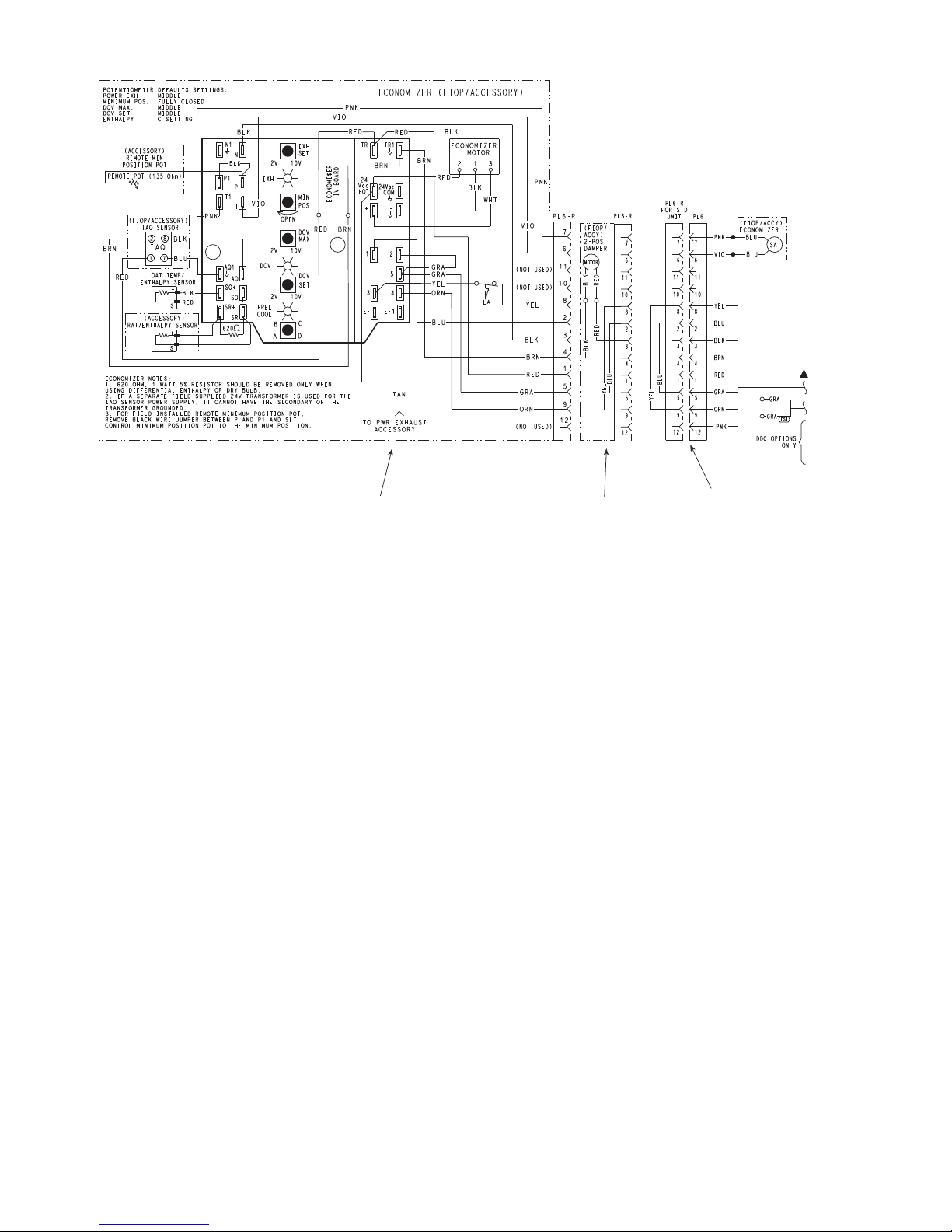
Economizer 2 Position Damper
Unit Without Economizer or
2 Position Damper
Fig. 65 — EconoMi$er
Step 14 — Adjust Factory-Installed Options
SMOKE DETECTORS — Smoke detector(s) will be con-
nected at the Controls Connections Board, at terminals marked
“Smoke Shutdown.” Cut jumper JMP 3 when ready to energize unit.
ECONOMI$ER IV OCCUPANCY SWITCH — Refer
to Fig. 65 for general EconoMi$er IV wiring. External occupancy control is managed through a connection on the Controls
Connections Board.
If external occupancy control is desired, connect a time
clock or remotely controlled switch (closed for Occupied, open
for Unoccupied sequence) at terminals marked OCCUPANCY.
Cut jumper JMP 2 to complete the installation.
Step 15 — Install Accessories — Available accessories
include:
•Roof Curb
• Thru-base connection kit (must be installed before unit is
set on curb)
• LP conversion kit
• Flue discharge deflector
• Manual outside air damper
• Two-Position motorized outside air damper
• EconoMi$er IV (with control)
• EconoMi$er2 (without control/for external signal)
• Power Exhaust
• Differential dry-bulb sensor (EconoMi$er IV)
• Outdoor enthalpy sensor
• Differential enthalpy sensor
•CO
sensor
2
• Louvered hail guard
• Motormaster
• Phase monitor control
• Energy Recovery Ventilator (ERV)
®
head pressure controls
®
IV Wiring
Refer to separate installation instructions for information on
installing these accessories.
Step 16 — Check Belt Tension — Measure the belt
span length as shown in Fig. 66. Calculate the required deflection by multiplying the belt span length by
the belt span length is 32 inches: 32 x
BELT FORCE — DEFLECTION METHOD — Check
the belt tension with a spring-force belt force deflection gauge
(available from drive belt manufacturer).
1. Place a straightedge along the belt between the two
pulleys. Measure the distance between the motor shaft
and the blower shaft.
2. Set the tension gauge to the desired tension (see Table 1
in Fig. 66). Place the large O-ring at that point.
3. Press the tension checker downward on the belt until the
large O-ring is at the bottom of the straightedge.
4. Adjust the belt tension as needed.
Adjust belt tension by loosing the motor mounting plate
front bolts and rear bolt (see Fig. 67) and slide the plate towards the fan (to reduce tension) or away from the fan (to increase tension). Ensure the blower shaft and motor shaft are
parallel to each other (pulleys aligned). Tighten all bolts securely when finished.
1
/64. For example, if
1
/64 = 1/2 inch deflection.
47
Page 48
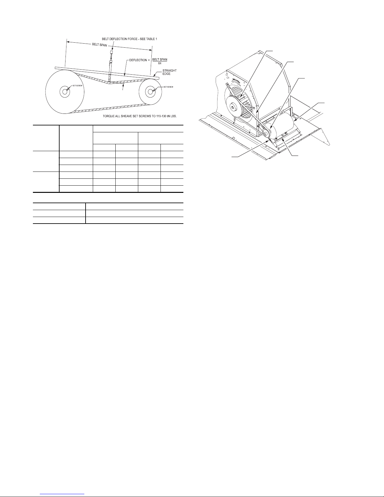
BELT TENSION METHOD — Requires belt tension
Table 1
Table 2
BELT
CROSS
SECTION
SMALLEST
SHEAVE
DIAMETER
BELT DEFLECTION FORCE (LBS)
UNNOTCHED
BELTS
NOTCHED BELTS
USED NEW USED NEW
A, AX
3.0-3.6 3.7 5.5 4.1 6.1
3.8-4.8 4.5 6.8 5.0 7.4
5.0-7.0 5.4 8.0 5.7 8.4
B, BX
3.4-4.2 — — 4.9 7.2
4.4-5.6 5.3 7.9 7.1 10.5
5.8-8.6 6.3 9.4 8.5 12.6
BELT CONDITION TENSION FORCE IN BELT (LBS)
New 100
Used 80
gauge that measures tension in belt in units of lbs force.
BLOWER PULLEY
V-B ELT
MOTOR
PULLEY
MOTOR
Fig. 66 — V-Belt Force Label
MOUNTING
BOLTS (4)
MOTOR MOUNTING
PLATE
Fig. 67 — Belt Drive Motor Mounting
Pre-Start and Start-Up — This completes the mechani-
cal installation of the unit. Refer to the unit’s Service Manual
for detailed Pre-Start and Start-Up instructions. Download the
latest versions from HVAC Partners (www.hvacpartners.com).
48
Page 49

Page 50

Copyright 2018 Bryant Heating & Cooling Systems Edition Date: 4/18 Printed in U.S.A Catalog No: II581J-4-6-01
Manufacturer reserves the right to change, at any time, specifications and designs without notice and without obligations. Replaces: II581J-13
Page 51

START-UP CHECKLIST FOR 581J 04-06 SINGLE PACKAGE ROOFTOP
GAS HEATING/ELECTRIC COOLING UNIT
(REMOVE AND USE FOR JOB FILE)
NOTE: To avoid injury to personnel and damage to equipment or
property when completing the procedures listed in this start-up
checklist, use good judgment, follow safe practices, and adhere to
the safety considerations/information as outlined in preceding
sections of this Installation Instruction document.
I. PRELIMINARY INFORMATION
MODEL NO__________________________________________________
JOB NAME __________________________________________________
SERIAL NO __________________________________________________
ADDRESS ___________________________________________________
START-UP DATE______________________________________________
TECHNICIAN NAME__________________________________________
ADDITIONAL ACCESSORIES
___________________________________________________________________________________________________________________
II. PRE-START-UP
Verify that all packaging materials have been removed from unit (Y/N) _____
Verify installation of outdoor air hood (Y/N) _____
Verify installation of flue exhaust and inlet hood (Y/N) _____
Verify that condensate connection is installed per instructions (Y/N) _____
Verify that all electrical connections and terminals are tight (Y/N) _____
Verify gas pressure to unit gas valve is within specified range (Y/N) _____
Check gas piping for leaks (Y/N) _____
Check that indoor-air filters are clean and in place (Y/N) _____
Check that outdoor air inlet screens are in place (Y/N) _____
Verify that unit is level (Y/N) _____
Check fan wheels and propeller for location in housing/orifice and verify setscrew is tight (Y/N) _____
Verify that fan sheaves are aligned and belts are properly tensioned (Y/N) _____
Verify that scroll compressors are rotating in the correct direction (Y/N) _____
Verify installation of thermostat (Y/N) _____
Verify that crankcase heaters have been energized for at least 24 hours (Y/N) _____
III. START-UP
ELECTRICAL
Supply Voltage L1-L2_____________ L2-L3_____________ L3-L1_____________
Compressor Amps 1 L1 _____________ L2 _____________ L3 _____________
Compressor Amps 2 L1 _____________ L2 _____________ L3 _____________
Supply Fan Amps L1 _____________ L2 _____________ L3 _____________
TEMPERATURES
Outdoor-air Temperature _____________ °F DB (Dry Bulb)
Return-air Temperature _____________ °F DB _____________ °F WB (Wet Bulb)
Cooling Supply Air Temperature _____________ °F
Gas Heat Supply Air _____________ °F
Manufacturer reserves the right to change, at any time, specifications and designs without notice and without obligations. CL-1 Replaces: II581J-13
Catalog No: II581J-4-6-01
Page 52

PRESSURES
Gas Inlet Pressure _____________ in. wg
Gas Manifold Pressure STAGE 1 _____________ in. wg
STAGE 2 _____________ in. wg
Refrigerant Suction CIRCUIT A _____________ PSIG
CIRCUIT B _____________ PSIG
Refrigerant Discharge CIRCUIT A _____________ PSIG
CIRCUIT B _____________ PSIG
Verify Refrigerant Charge using Charging Charts (Y/N) _____
GENERAL
Economizer minimum vent and changeover settings to job requirements (if equipped) (Y/N) _____
Verify smoke detector unit shutdown by utilizing magnet test (Y/N) _____
IV. PERFECT HUMIDITY® START-UP
STEPS
1. Check CTB for jumper 5, 6, 7 (Jumper 5, 6, 7 must be cut and open) (Y/N) _____
2. Open humidistat contacts (Y/N) _____
3. Start unit In cooling (Close Y1) (Y/N) _____
OBSERVE AND RECORD
A. Suction pressure _______________ PSIG
B. Discharge pressure _______________ PSIG
C. Entering air temperature _______________ °F
D. Liquid line temperature at outlet or reheat coil _______________ °F
E. Confirm correct rotation for compressor (Y/N) _____
F. Check for correct ramp-up of outdoor fan motor as condenser coil warms (Y/N) _____
4. Check unit charge per charging chart (Y/N) _____
(Jumper 32L Motormaster
5. Switch unit to high-latent mode (sub-cooler) by closing humidistat with Y1 closed (Y/N) _____
OBSERVE
A. Reduction in suction pressure (5 to 7 psi expected) (Y/N) _____
B. Discharge pressure unchanged (Y/N) _____
C. Liquid temperature drops to 50 to 55°F range (Y/N) _____
D. LSV solenoid energized (valve closes) (Y/N) _____
6. Switch unit to dehumid (reheat) by opening Y1 (Y/N) _____
OBSERVE
A. Suction pressure increases to normal cooling level
B. Discharge pressure decreases (35 to 50 psi) (Limited by Motormaster control)
C. Liquid temperature returns to normal cooling level
D. LSV solenoid energized (valve closes)
E. DSV solenoid energized, valve opens
7. With unit in dehumid mode close W1 compressor and outdoor fan stop; LSV and DSV solenoids de-energized
(Y/N) _____
8. Open W1 restore unit to dehumid mode (Y/N) _____
9. Open humidistat input compressor and outdoor fan stop; LSV and DSV solenoids de-energized (Y/N) _____
10. Restore set-points for thermostat and humidistat (Y/N) _____
®
temperature sensor during this check. Remove jumper when complete.)
CUT ALONG DOTTED LINE CUT ALONG DOTTED LINE
Copyright 2018 Bryant Heating & Cooling Systems Edition Date: 4/18 4-18A Printed in U.S.A Catalog No: II581J-4-6-01
Manufacturer reserves the right to change, at any time, specifications and designs without notice and without obligations. CL-2 Replaces: II581J-13
- - - - - - - - - - - - - - - - - - - - - - - - - - - - - - - - - - - - - - - - - - - - - - - - - - - - - - - - - - - - - - - - - - - - - - - - - - - - - - - - - - - - - - - - - - - - - - - - - - - - - - - - - - - - - - - - - - - - - - - - - - - - - - - - - - - - - - - - - - - - - - - - - - - - - - - - - - - - - - - - - - - - - - - - - - - - -- - - - - - - - - - - - - - - - - - - -
 Loading...