

Bryant 574DNWA24040AA, 574DNWA24060NA, 574DNWA24040NA, 574DNWA24060AA, 574DNWA30040AA Product Data
...
574D----A
LEGACYt 13 SEER
SINGLE--PACKAGED AIR CONDITIONER AND GAS FURNACE SYSTEM
WITH PURONR (R--410A) REFRIGERANT SINGLE AND THREE PHASE
2 TO 5 NOMINAL TONS (SIZES 24--60)
Product Data
Innovative Unit Base Design
On the inside a high --tech composite material will not rust and
incorporates a sloped drain pan which improves drainage and helps
inhibit mold, algae and bacterial growth. On the outside metal base
rails provide added stability as well as easier handling and rigging.
Convertible duct configuration
Unit is designed for use in either downflow or horizontal
applications. Each unit can be converted from horizontal to
downflow and includes horizontal duct covers. Downflow
operation is provided in the field to allow vertical ductwork
connections. The basepan seals on the bottom openings to ensure a
positive seal in the vertical airflow mode.
Efficient operation High--efficiency design offers SEER
(Seasonal Energy Efficiency Ratios) of up to 13.5 and AFUE
(Annual Fuel Utilization Efficiency) ratings as high as 80.4%.
Energy--saving, direct spark ignition saves gas by operating only
when the room thermostat calls for heating. Standard units are
furnished with natural gas controls. A low--cost field installed kit
for propane conversion is available for all units.
A09034
Fig. 1 -- Unit 574D----A
Single--Packaged Products with Energy-- Saving Features and
PuronR refrigerant.
S Up to 13.5 SEER
S Up to 80.4% AFUE
S Factory--Installed TXV
S ECM Motor--Standard
S Direct Spark Ignition
S Low Sound Levels
S Dehumidification Feature
FEATURES/BENEFITS
One--piece heating and cooling units with low sound levels, easy
installation, low maintenance, and dependable performance.
Puron Environmentally Sound Refrigerant is Bryant’s unique
refrigerant designed to help protect the environment. Puron is an
HFC refrigerant which does not contain chlorine that can harm the
ozone layer. Puron refrigerant is in service in millions of systems,
proving highly reliable, environmentally sound performance.
Easy Installation
Factory--assembled package is a compact, fully self--contained,
combination gas heating/electric cooling unit that is prewired,
pre--piped, and pre--charged for minimum installation expense.
These units are available in a variety of standard and optional
heating/ cooling size combinations with voltage options to meet
residential and light commercial requirements. Units are
lightweight and install easily on a rooftop or at ground level. The
high tech composite base eliminates rust problems associated with
ground level applications.
Low NOx units are designed for California installations. These
models meet the California maximum oxides of nitrogen (NOx)
emissions requirement of 40 nanograms/joule or less as shipped
from the factory and MUST be installed in California Air Quality
Management Districts and wherever a Low NOx rule exists.
Durable, dependable components Compressors are designed
for high efficiency. Each compressor is hermetically sealed against
contamination to help promote longer life and dependable
operation. Each compressor also has vibration isolation to provide
quieter operation. All compressors have internal high pressure and
overcurrent protection.
Monoport inshot burners produce precise air--to--gas mixture,
which provides for clean and efficient combustion. The large
monoport on the inshot (or injection type) burners seldom, if ever,
requires cleaning. All gas furnace components are accessible in one
compartment.
Turbo--tubulart heat exchangers are constructed of aluminized
steel for corrosion resistance and optimum heat transfer for
improved efficiency. The tubular design permits hot gases to make
multiple passes across the path of the supply air.
In addition, dimples located on the heat exchanger walls force the
hot gases to stay in close contact with the walls, improving heat
transfer.
ECM Motor is standard on all 574D-- -- A models.
Direct--drive PSC (Permanent Split Capacitor) condenser--fan
motors are designed to help reduce energy consumption and
provide for cooing operation down to 40_F(4.4_C) outdoor
temperature. Motormasterr II low ambient kit is available as a
field--installed accessory.
Thermostatic Expansion Valve -- A hard shutoff, balance port
TXV maintains a constant superheat at the evaporator exit (cooling
cycle) resulting in higher overall system efficiency.
Refrigerant system is designed to provide dependability. Liquid
filter driers are used to promote clean, unrestricted operation. Each
unit leaves the factory with a full refrigerant charge. Refrigerant
service connections make checking operating pressures easier.
1

High and Low Pressure Switches provide added reliability for the
compressor.
Indoor and Outdoor coils are computer--designed for optimum
heat transfer and efficiency. The indoor coil is fabricated from
copper tube and aluminum fins and is located inside the unit for
protection against damage. The outdoor coil is internally mounted
on the top tier of the unit. Copper fin coils and pre--coated fin coils
are available from the factory by special order. These coils are
recommended in applications where aluminum fins are likely to be
damaged due to corrosion. They are ideal for seacoast applications.
Low sound ratings ensure a quiet indoor and outdoor
environment with sound ratings as low as 75dBA.
Easy to service cabinets provide easy 3--panel accessibility to
serviceable components during maintenance and installation. The
basepan with integrated drain pan provides easy ground level
installation with a mounting pad. A nesting feature ensures a
positive basepan to roof curb seal when the unit is roof mounted. A
convenient 3/4--in. (19.05 mm) wide perimeter flange makes frame
mounting on a rooftop easy.
Horizontal metal duct covers are standard with insulation come
with the unit and cover the horizontal duct openings. These can be
left in place if the units are converted to downflow.
Integrated Gas Control (IGC) board provides safe and efficient
control of heating and simplifies trouble--shooting through its
built--in diagnostic function.
Cabinets are constructed of heavyduty, phosphated, zinc--coated
prepainted steel capable of withstanding 500 hours in salt spray.
Interior surfaces of the evaporator/heat exchanger compartment are
insulated with cleanable semi--rigid insulation board, which keeps
the conditioned air from being affected by the outdoor ambient
temperature and provides improved indoor air quality. (Conforms
to American Society of Heating, Refrigeration and Air
Conditioning Engineers 62.2.) The sloped drain pan minimizes
standing water in the drain. An external drain is provided.
574D-- --A
Features/Benefits 1---2..............................
Model Number Nomenclature 3.......................
AHRI Capacities 4..................................
P h y s i c a l Da t a 5 --- 6..................................
Options and Accessories 7...........................
Base Unit Dimensions 9---10.........................
Accessory Dimensions 11............................
Selection Procedure 12..............................
Pe r f o r m a n c e D a ta 1 3 --- 2 9............................
Typical Piping and Wiring 30..........................
Application Data 31.................................
Electrical Data 32...................................
TABLE OF CONTENTS
Typical Wiring Schematics 33---38.....................
Controls 39........................................
Guide Specifications 40---41..........................
2
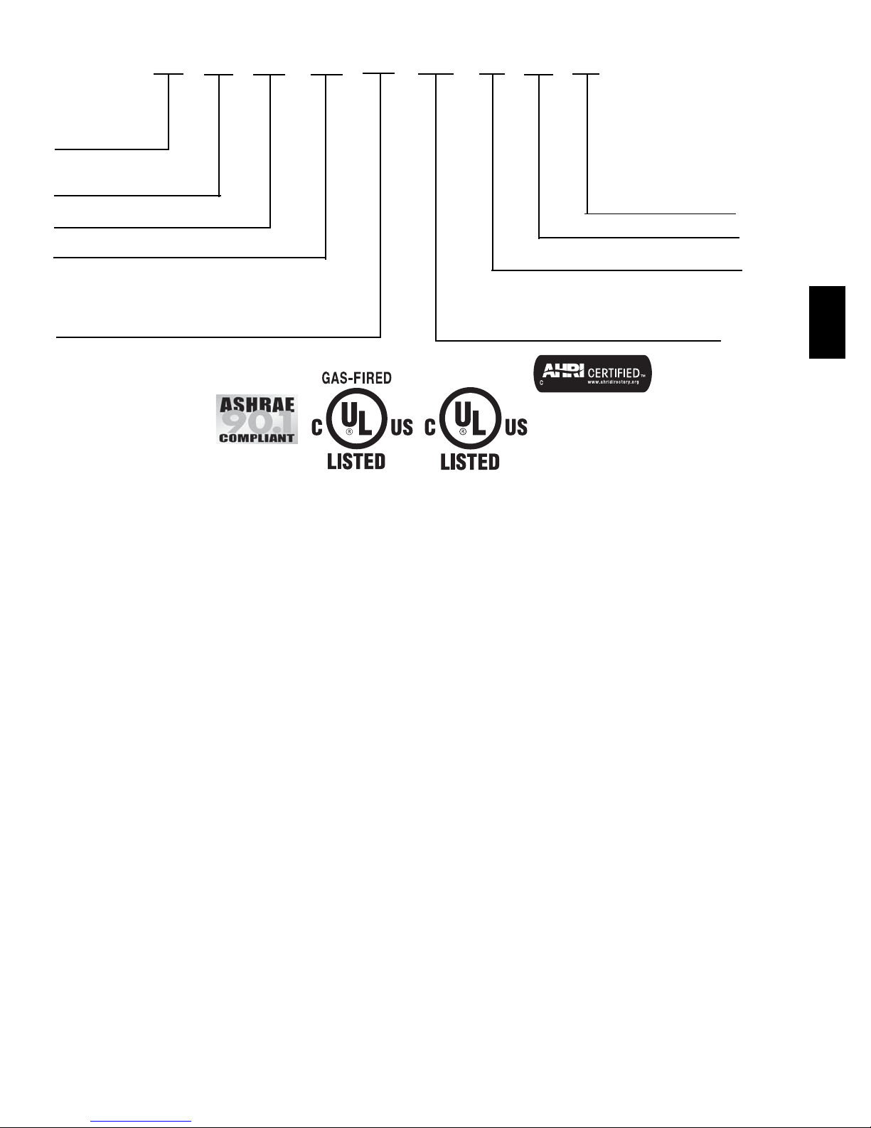
MODEL NUMBER NOMENCLATURE
574D
N
W
A
24
000
A
A
--- ---
Typ e o f Un i t
574D --- Single Packaged
Gas Heating/Electric
Cooling Unit
Electrical Supply
N --- 208/230--- 1--- 60
P --- 208/230--- 3--- 60
E --- 46 0 --- 3 --- 6 0
Fuel and Controls
W --- Na t u r a l G a s
Major Series
Nominal Cooling Capacity
24 --- 2.0 Tons
30 --- 2.5 Tons
36 --- 3.0 Tons
42 --- 3.5 Tons
48 --- 4.0 Tons
60 --- 5.0 Tons
Brand Name
A --- Co m m o n U n i t
Heat Input Size (Btuh)
40,000
60,000
90,000
115,000
130,000
Vari a ti ons
FE --- Economizer (3 Phase Only)
GP--- Tin plated i ndoor coil hairpins and Stai nless Steel
HX (Single Phase Only)
GS --- Stainless Steel HX
SE --- Economizer and Stainless Steel HX (3 Phase
Only)
TP --- Base unit wi th tin plated i ndoor coil hairpins
(Single Phase Onl y)
See Price Page f or full list of factory options.
Only used if ordering an option
Minor Series
Use of the AHRI Certified
TM Mark indicates a
manufacturer’s
participation in the
program For verification
of certification for individual
products, go to
www.ahridirectory.org.
574D-- --A
3
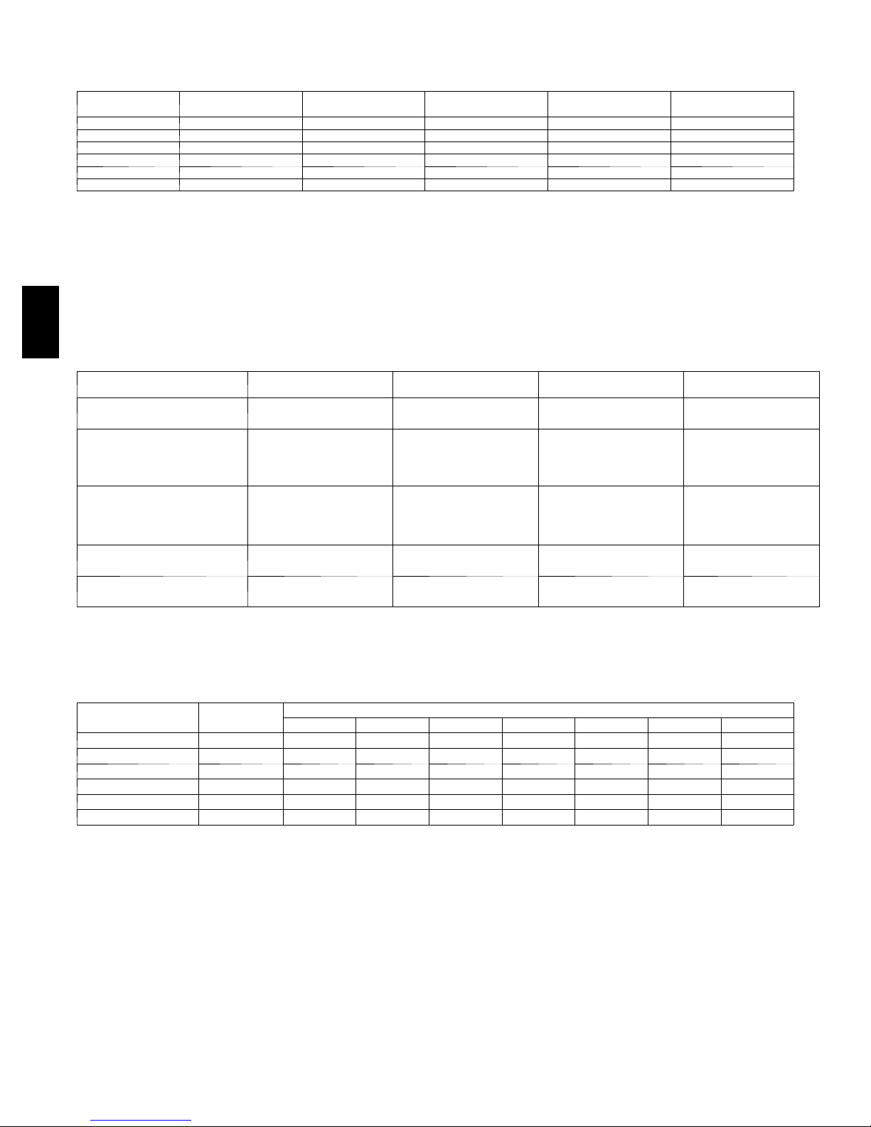
AHRI* CAPACITIES
Cooling Capacities and Efficiencies
UNIT 574D-- --A NOMINAL TONS STANDARD CFM
24 2 800 23,000 11.0 13.2
30 2-- 1/2 1000 28,400 11.2 13.5
36 3 1200 34,400 11.0 13.0
42 3-- 1/2 1400 40,500 11.2 13.2
48 4 1600 46,500 11.2 13.2
60 5 1750 57,000 11.0 13.4
LEGEND
d B --- Sound Levels (decibels)
db—Dry Bu lb
SEER—Seasonal Energy Efficiency Ratio
wb—Wet Bulb
COP---Coefficient of Performance
* Air Conditioning, Heating & Refrigeration Institute.
**At “ A” condition s - --80_F (26.7_C) indoor db/67_F ( 19.4_ C) indoor wb &
95_F(35_C) outdoor db.
{ Rated in accordance with U.S. Government DOE Department of Energy)
test procedures and/or ARI Stan dards 210/240.
574D-- --A
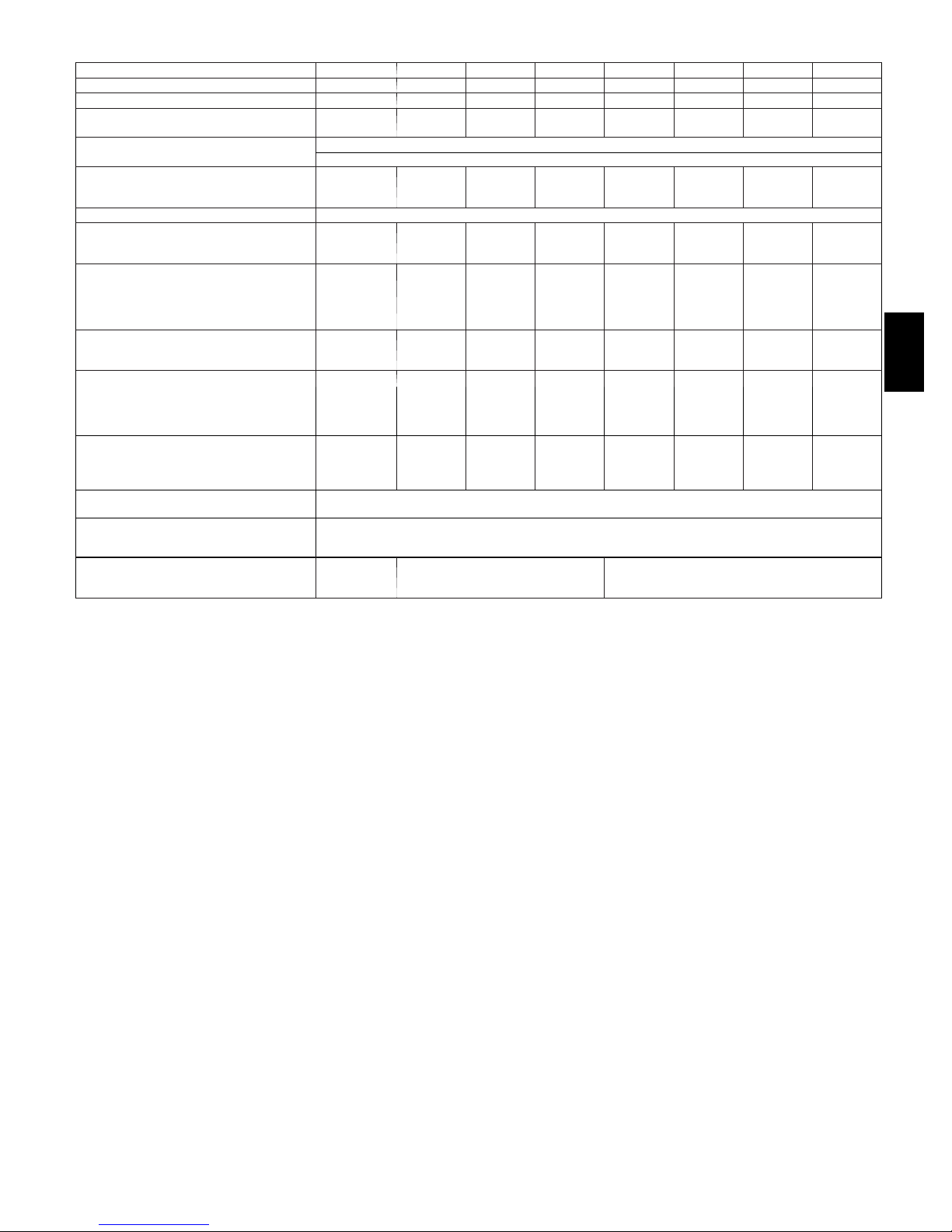
Gas Heating Capacities and Efficiencies
UNIT 574D-- --A HEATING INPUT (Btuh)
24040
30040
40,000 32,000
24060
30060
36060
60,000
42060
36090
42090
48090
90,000
60090
48115
60115
48130
60130
LEGEND
AFUE—Annual Fuel Utilization Efficiency
NOTE: Before purchasing this appliance, read importan t en ergy cost and efficiency information available from your retailer.
115,000 93,000
130,000 103,000
NET COOLING
CAPACITIES (Btuh)
Notes:
1. Ratings are net values, reflecting the effects of circulating fan heat.
Ratings are based on:
Cooling Standard: 80°F (26.7_C) db, 67°F wb (19.4_C ) i n d o o r e n t e r i n g --- a ir
temperature and 95°Fdb(35_C) outdoor entering ---air temperature.
2. Before purchasing this appliance, read important energy cost and efficiency information available from your retailer.
OUTPUT CAPACITY
(Btuh)
48,000
48,000
48,000
47,000
72,000
73,000
73,000
73,000
EER** SEER†
TEMPERATURE RISE
RANGE °F(°C)
30--60
(16.7--33.3)
25--55
(13.9--30.6)
35--65
(19.4--36.1)
30--60
(16.7--33.3)
35--65
(19.4--36.1)
AFUE (%)
80.0
80.0
80.0
80.0
78.5
79.3
80.4
80.4
80.4
80.3
78.9
A--Weighted Sound Power Level (dBA)
UNIT 574D-- --A
24 76 66.0 66.0 70.5 71.5 67.5 62.5 58.5
30 75 66.0 63.5 68.0 68.5 67.5 61.5 55.0
36 75 64.0 63.5 68.0 70.5 64.5 61.0 61.0
42 77 67.0 67.0 69.5 70.5 68.0 65.5 61.0
48 78 71.5 66.5 73.0 71.5 68.0 64.0 57.0
60 78 74.5 66.5 70.0 70.0 66.5 64.0 57.0
* Tested in accordance with AHRI Standard 270 (not listed in AHRI).
STANDARD
RATING dBA
125 250 500 1000 2000 4000 8000
TYPICAL OCTAVE BAND SPECTRUM (dBA without tone adjustment)
4
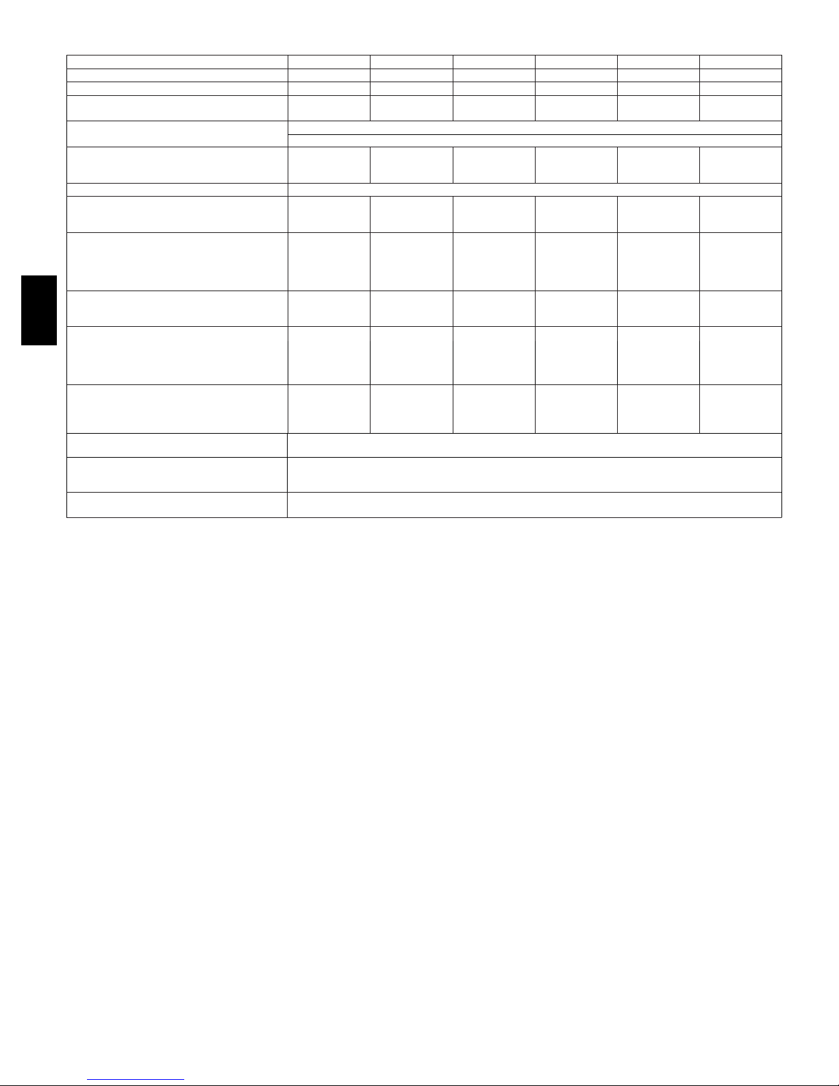
PHYSICAL DATA
UNIT SIZE 24040 24060 30040 30060 36060 36090 42060 42090
NOMINAL COOLING CAPACITY (ton) 2 2 2 --- 1 / 2 2 --- 1 / 2 3 3 3 --- 1 / 2 3 --- 1 / 2
NOMINAL HEATING INPUT (Btu/hr) 40,000 60,000 40,000 60,000 60,000 90,000 60,000 90,000
SHIPPING WEIGHT* * lb.
SHIPPING WEIGHT* * (kg)
COMPRESSORS
Quantity
REFRIGERANT (R -- -410A)
Quantity lb.
Quantity (kg)
REFRIGERANT METERING DEVICE TXV
OUTDOOR COIL
Rows...Fins/in.
Face Area ( sq ft)
OUTDOOR FAN
Nominal CFM
Diameter in.
Diameter (mm)
Motor Hp (Rpm)
INDOOR COIL
Rows...Fins/in.
Face Area ( sq ft)
INDOOR BLOWER
Nominal Cooling Airflow (Cfm)
Size in.
Size (mm.)
Motor HP (RPM)
FURNACE SECTION*
Burner Orifice No. (Qty...Drill Size)
Natural Gas Factory Installed
Propane Gas
HIGH--PRESSURE SWITCH
(psig) Cut-- out Reset (Auto)
LOSS-- OF--CHARGE / LOW--PRESSURE
SWITCH (Liquid Line) (psig) cut-- out Reset
(auto)
RETURN--- AIR FILTERS†}
Throwaway Size in.
(mm)
311
141
4.8
2.2
1..21
10.2
2800
24
609.6
1/5 (810)
2...17
3.7
800
10x10
254x254
1/2 (1050)
2...44
2...55
20x20x1
508x508x25
311
141
4.8
2.2
1...21
10.2
2800
24
609.6
1/5 (810)
2...17
3.7
800
10x10
254x254
1/2 (1050)
2...38
2...53
316
143
6.2
2.8
1...21
11.9
3000
24
609.6
1/5 (810)
3...17
3.7
1000
10x10
254x254
1/2 (1050)
2...44
2...55
20x24x1
508x610x25
316
143
6.2
2.8
1...21
11.9
3000
24
609.6
1/5 (810)
3...17
3.7
1000
10x10
254x254
1/2 (1050)
2...38
2...53
650 +/-- 15
420 +/-- 25
45 +/-- 10
Scroll
1
20 +/-- 5
326
148
6.4
2.9
1...21
15.4
3200
24
609.6
1/5 (810)
3...17
3.7
1200
11x10
279.4x254
3/4 (1000)
2...38
2...53
326
148
6.4
2.9
1...21
15.4
3200
24
609.6
1/5 (810)
3...17
3.7
1200
11x10
279.4x254
3/4 (1000)
3...38
3...53
610x762x25
24x30x1
420
191
6.1
2.7
1...21
13.6
3600
26
660.4
1/5 (810
3...17
4.7
1400
11x10
279.4x254
3/4 (1075)
2...38
2...53
420
191
6.1
2.7
1...21
13.6
3600
26
660.4
1/5 (810)
3...17
4.7
1400
11x10
279.4x254
3/4 (1075)
3...38
3...53
574D-- --A
5
PHYSICAL DATA (CONT)
1600
1600
1600
1750
1750
UNIT SIZE 48090 48115 48130 60090 60115 60130
NOMINAL CAPACITY (ton) 4 4 4 5 5 5
NOMINAL HEATING INPUT (Btu/hr) 90,000 115,000 130,000 90,000 115,000 130,000
SHIPPING WEIGHT* * lb
SHIPPING WEIGHT* * kg
COMPRESSORS
Quantity
REFRIGERANT (R -- -410A)
Quantity lb
Quantity (kg.)
REFRIGERANT METERING DEVICE TXV
OUTDOOR COIL
Rows...Fins/in.
Face Area ( sq ft)
OUTDOOR FAN
Nominal Cfm
Diameter in.
Diameter (mm)
Motor Hp (Rpm)
INDOOR COIL
Rows...Fins/in.
Face Area ( sq ft)
INDOOR BLOWER
574D-- --A
Nominal Cooling Airflow (Cfm)
Size in.
Size (mm)
Motor HP (RPM)
FURNACE SECTION*
Burner Orifice No.
Natural Gas Qty...Drill Size (Factory Installed)
Propane Gas
HIGH--PRESSURE SWITCH
(psig) Cut-- out Reset (Auto)
LOSS-- OF--CHARGE / LOW--PRESSURE
SWITCH (Liquid Line) (psig) cut-- out Reset
(auto)
RETURN--AIR FILTERS Throwaway†} in.
(mm)
*Based on altitude of 0 to 2000 ft (0 ---610 m).
{ Required filter sizes shown are based on the larger of the AHRI (Air Conditioning, Heating and Refrigeration Institute) rated cooling airflow or the heating
airflow velocity of 300 ft/minute for throwaway type. Air filter pressure drop for non---standard filters must not exceed 0.08 IN. W.C.
} If using accessory filter rack refer to the filter rack installation instructions for correct filter sizes and quantity.
** For 460 volt units, a dd 14 lbs (6.35 kg) to the shipping weight.
428
194
6.4
2.9
1...21
15.5
4000
26
660.4
1/5 (810)
3...17
4.7
1600 1600 1600 1750 1750
11x10
279.4x254
1.0 (1075)
3...38
3...53
428
194
6.4
2.9
1...21
15.5
4000
26
660.4
1/5 (810)
3...17
4.7
11x10
279.4x254
1.0 (1075)
3...33
3...51
428
194
6.4
2.9
1...21
15.5
4000
26
660.4
1/5 (810)
3...17
4.7
11x10
279.4x254
1.0 (1075)
3...31
3...49
Scroll
1
650 +/-- 15
420 +/-- 25
20 +/-- 5
45 +/-- 10
24x36x1
610x914x25
450
204
10.0
4.5
2...21
15.5
3200
26
660.4
1/5 (810)
3...17
5.7
11x10
279.4x254
1.0 (1040)
3...38
3...53
450
204
10.0
4.5
2...21
15.5
3200
26
660.4
1/5 (810)
3...17
5.7
11x10
279.4x254
1.0 (1040)
3...33
3...51
450
204
10.0
4.5
2...21
15.5
3200
26
660.4
1/5 (810)
3...17
5.7
1750
11x10
279.4x254
1.0 (1040)
3...31
3...49
6
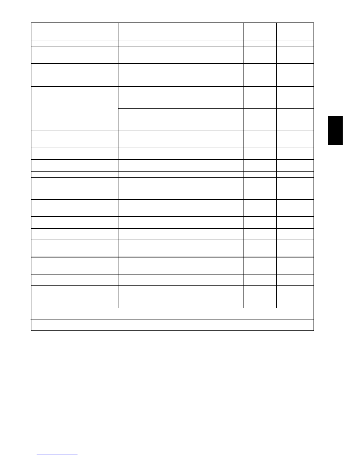
OPTIONS AND ACCESSORIES
FACTORY
ITEM DESCRIPTION
Coil Options Base unit with tin plated indoor coil hairpins X
Compressor Start Kit assists compressor start---up by
Compressor Start Kit
Corporate Thermostats
Crankcase Heater
Economizer
Filter Rack
Flat Roof Curbs
Flue Discharge Deflector
Heat Exchanger Stainless Steel Heat Exchanger X
High Altitude Propane Conversion Kit
Low Ambient Kit
Louver Metal Outdoor Coil Grilles
Manual Outside Air Damper
Natural to Propane Gas Conversion Kit
Propane to Natural Gas Conversion Kit
S q u a r e --- t o --- R o u n d D u c t T r a n s i t i o n K i t
Time Guard II
Curb Adapter
Gasket Kit
*Refer to Price Page for application detail.
providing additional starting torque on sing phase units
only.
Thermostats provide control for the system heating and
cooling functions.
Crankcase Heater provides anti--- floodback protection for
low--- load cooling applications.
Horizontal Economizer with solid state controls and barometric relief dampers includes filter racks and provide
outdoor air during cooling and reduce compressor operation.
Vertical Economizer with solid state controls and barometric relief dampers includes filter racks and provide
outdoor air during cooling and reduce compressor operation.
Filter Rack features easy installation, serviceability, and
high--- filtering performance for vertical applications.
Includes 1 --- in. (25 mm) filter.
F l a t R o o f C u r b s i n b o t h 1 1 --- i n ( 2 7 9 m m ) a n d 1 4 --- i n . ( 3 5 6
mm) sizes are available for roof mounted applications.
Directs flue gas exhaust 90 degrees upward from current
discharge.
High Altitude Propane Conversion Kit is for use at 2001 to
6000 ft. (611 ---1829 m) above sea level. Kit consists of
propane g as orifices that compensate for gas heat operation at high altitude.
Low Ambient Kit (Motormaster II Control) allows the use of
mechanical cooling down to outdoor temperatures as low
as 0° F (--- 18° C) when properly installed.
Louver Metal Outdoor Coil Grilles provides hail and
vandalism protection.
Manual Outside Air Damper includes hood and filter rack
with adjustable damper blade for up to 25% outdoor air.
Natural to Propane Gas Conversion Kit allows for conversion from natural gas to propane gas (0 --- 2000 ft) (0--- 610
m)
Propane to Natural Gas Conversion Kit allows for conversion from propane to natural gas for altitudes of 0--- 2000 ft
( 0 --- 6 1 0 m )
S q u a r e --- t o --- R o u n d D u c t T r a n s i t i o n K i t e n a b l e 2 4 --- 4 8 s i z e
units to be fitted to 14 in. (356 mm) round ductwork.
Automatically prevents the compressor from restarting for
at least 4 minutes and 45 seconds after shutdown of the
compressor. Not required when a corporate programmable thermostat is applied.
Adapter curb for new unit with base rail installed on existing curb
For field modified existing roof curb with new base rail
unit.
INSTALLED
OPTION
X X
FIELD
INSTALLED
ACCESSORY
X
X
X*
X
X
X
X
X
X
X
X
X
X
X
X
X
574D-- --A
7
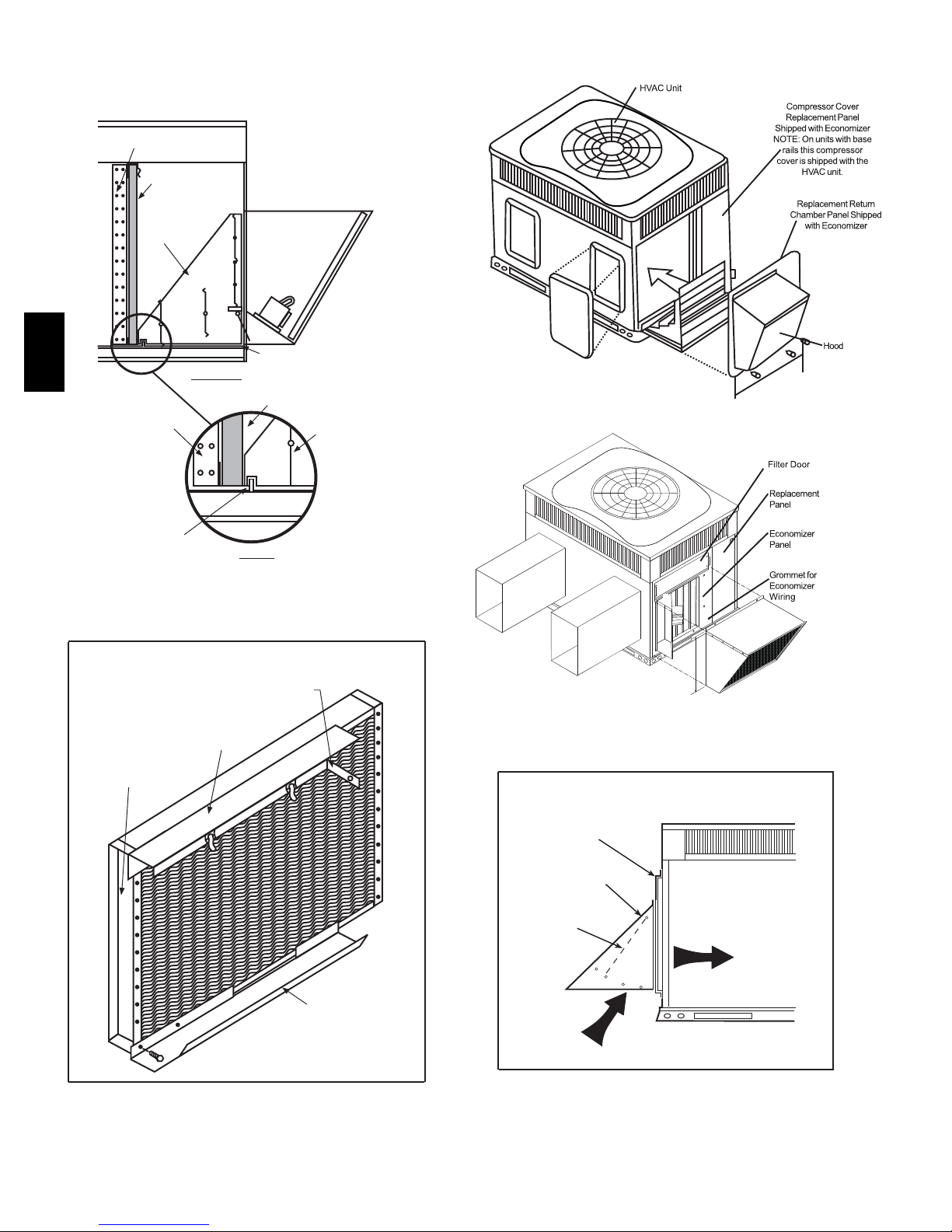
BASE
ECONOMIZER
COIL
FILTER
ECONOMIZER
CAULK BOTTOM CORNER
OF ECONOMIZER
574D-- --A
SIDE VIEW
COIL
ON EACH SIDE
FI LT ER
Vertical Economizer
ECONOMIZER
FLANGE
ON BASE
EV APORATOR
COIL
AIL
DET
FILTER RACK
BEND FLANGE AT 90° -SCREW TO
DIVIDER WITH 1-IN. (25 mm)
TOP FILTER RACK
SCREW
Horizontal Economizer
MANUAL OUTSIDE AIR DAMPER
REPLACEMENT
PANEL
MANUAL OUTSIDE
AIR HOOD
DAMPER
BLADE
BOTTOM FILTER
RACK
A09375
8
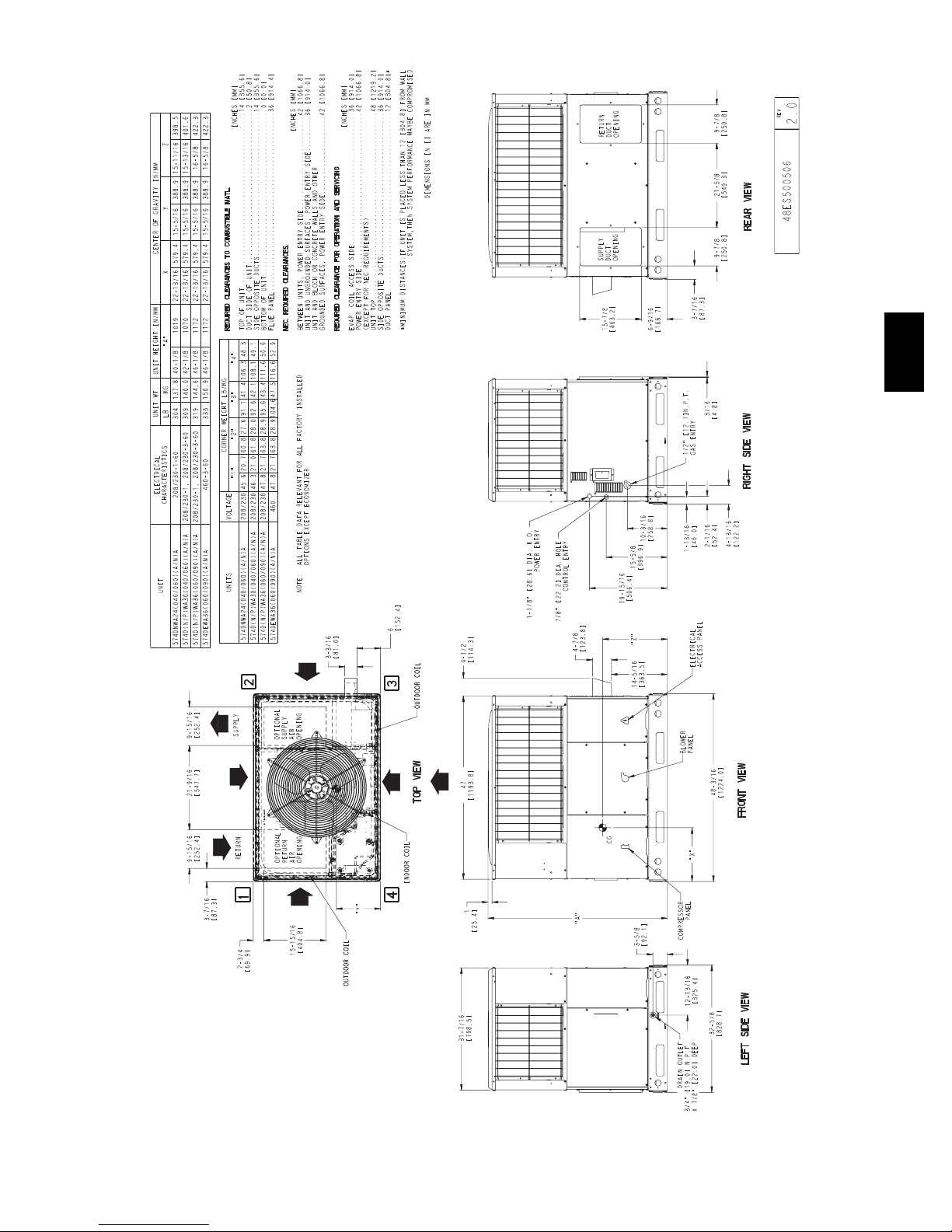
UNIT DIMENSIONS -- 574D----A24--36
574D-- --A
A09469
9
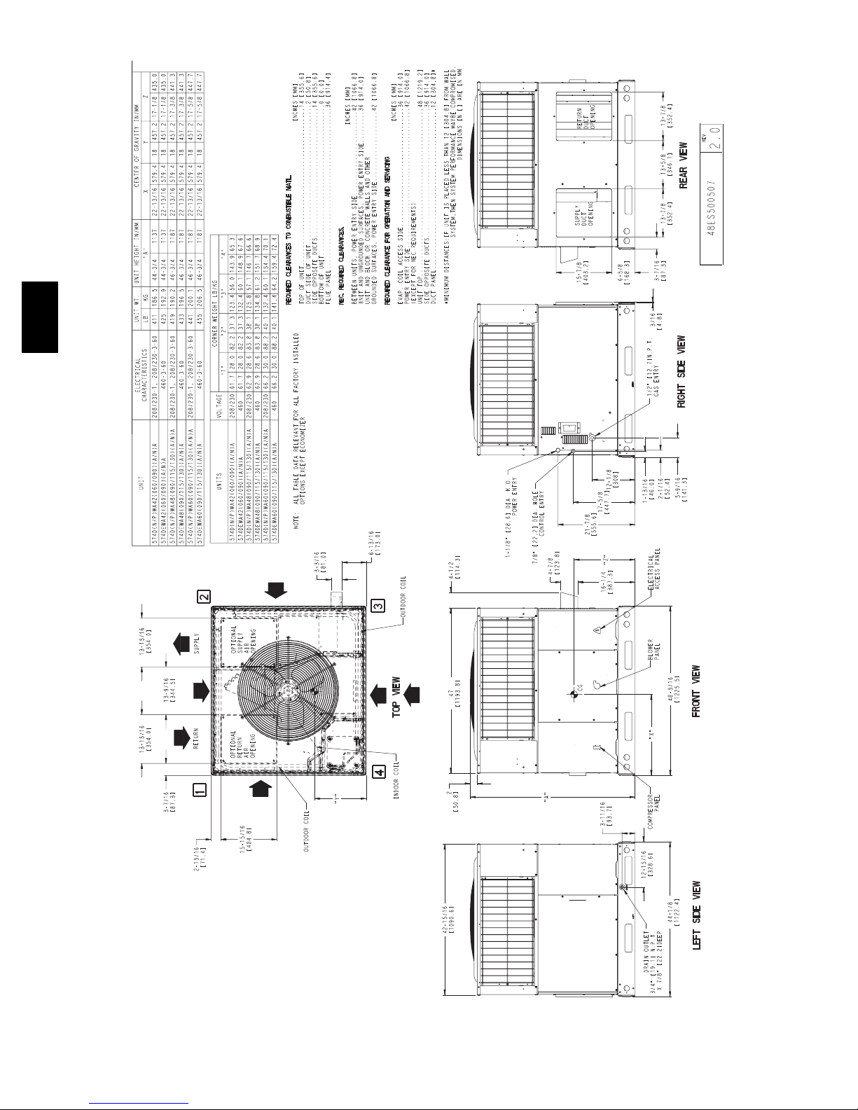
UNIT DIMENSIONS -- 574D----A42--60
574D-- --A
A09470
10
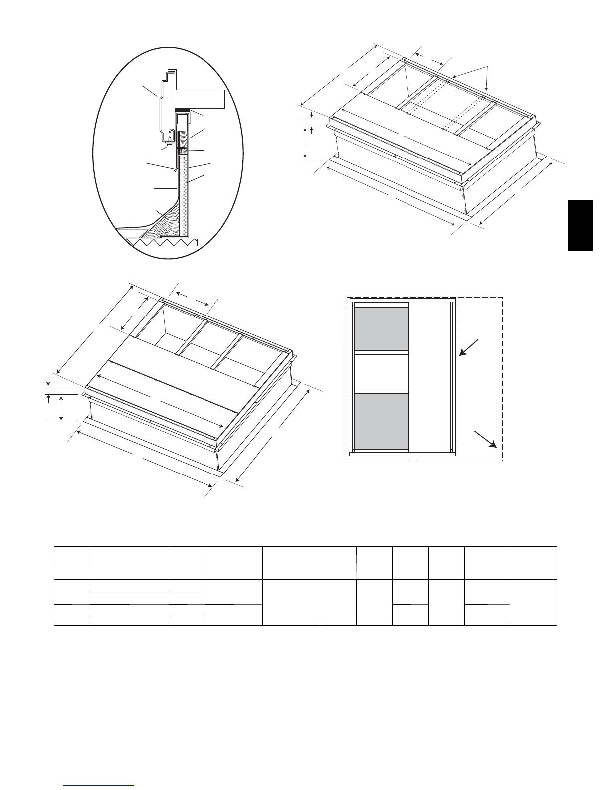
ACCESSORY DIMENSIONS
G
HVAC unit
base rails
Anchor screw
Flashing field
supplied
Roofing material
field supplied
Cant strip
field supplied
*Provided with roofcurb
HVAC unit
basepan
ROOF CURB DETAIL
B
C
Sealing
Gasket
Roofcurb
Wood nailer*
Roofcurb*
Insulation
(field supplied)
A09090
G
C
F
A
SMALL/COMMON CURB
SUPPLY
AIR
B
H
D
Dashed lines show cross support
location for large basepan units.
E
A09413
574D-- --A
SMALL
BASE
UNIT
A
F
RETURN
E
AIR
LARGE
BASE
UNIT
D
UNIT PLACEMENT ON
H
COMMON CURB
B (small /
common
base)
IN. (mm)*
10 (254)
14 (356)
A09415
B (large base)
IN. (mm)*
14 (356) 16 (406)
C
IN.
(mm)
LARGE CURB
UNIT
SIZE
Small
or
Large
Large
* Part Numbers CPRCURB010A00 and CPRCURB011A00 can be used on both small and large basepan un its. T he cross supports must be located based on
whether the unit is a small basepan or a large basepan.
NOTES:
1. Roof curb must be set up for unit being installed.
2. Seal strip must be applied, as required, to unit being installed.
3. Roof curb is made of 16-- gauge steel.
4. Attach ductwork to curb (flanges of duct rest on curb).
5. Insulated panels: 1--in. (25.4 mm) thick fiberglass 1 lb. density.
CATALOG
NUMBER
CPRFCURB010A00 11 (279)
CPRFCURB011A00 14 (356)
CPRFCURB012A00 11 (279)
CPRFCURB013A00 14 (356)
A
IN.
(mm)
SMALL OR LARGE BASE UNIT
D
IN.
(mm)
47.8
(1214)
E
IN.
(mm)
32.4
(822)
43.9
(1116)
F
IN.
(mm)
2.7 (69)
G
IN. (mm)HIN. (mm)
30.6 (778)
42.2 (1072)
A09094
46.1 (1170)
A09414
11

SELECTION PROCEDURE (WITH EXAMPLE)
1. Determine cooling and heating requirements at
design conditions:
Given:
Required Cooling Capacity (TC) 34,000 Btuh..........
Sensible Heat Capacity (SHC) 25,000 Btuh............
Required Heating Capacity 60,000 Btuh...............
Condenser Entering Air Temperature 95°F(35°C).......
Indoor--Air Temperature 80°F(26°C)edb 67°F(19°C) ewb
Evaporator Air Quantity 1200 CFM..................
External Static Pressure 0.30 in. W.C..................
Electrical Characteristics 230--1--60...................
2. Select uni t based on required cooling capacity.
Enter Net Cooling Capacities table at condenser entering
temperature of 95°F(35°C). Unit 036 at 1200 CFM and 67°F
(19°C) ewb (entering wet bulb) will provide a total capacity of
34,400 Btuh and a SHC of 25,900 Btuh. Calculate SHC correction,
if required, using Note 4 under Cooling Capacities tables.
574D-- --A
3. Select heating capacity of unit to provide design
condition requirement.
In the Heating Capacities and Efficiencies table, note that the unit
036090 will provide 72,000 Btuh with an input of 90,000 Btuh.
4. Determine fan speed and power requirements at
design conditions.
Before entering the air delivery tables, calculate the total static
pressure required. From the given example, the Wet Coil Pressure
Drop Table, and the Filter Pressure Drop Table:
External Static Pressure 0.30 in. W.C.
Filter 0.13 in. W.C.
Wet Coil Pressure Drop 0.10 in. W
Total Static Pressure 0.53 in. W.C
Enter the table for Dry Coil Air Delivery—Horizontal and
Downflow Discharge. At .53 in. W.C. ESP, the closest speed to
1200 CFM is Med--High (orange wire), which delivers 1316 CFM
at .6 in ESP.
.C
5. Select unit that corresponds to power source
available.
The Electrical Data Table shows that the unit is designed to operate
at 230--1--60.
12
KW
Sys
Tot a l
Capacity MBtuh
KW
Sys
Tot a l
574D-- --A
Capacity MBtuh
KW
Sys
Tot a l
Capacity MBtuh
CONDEN SER ENTER ING AIR TEMPERATURES _F(_C)
Tot a l
Tot a l
Tot a l
75 (23.9) 85 (29.4) 95 (35) 105 (40.6) 115 (46.1) 125 (51.7)
EWB
Capacity MBtuh
Capacity MBtuh
Capacity MBtuh
KW
Sys
KW
Sys
kW
Sys
Tot a l Sens Tot a l Sens Tot a l Sens To t a l Sens To t al Sens Tot a l Sens
22.74 22.74 1.66 21.26 21.26 1.85 19.77 19.77 2.06 18.28 18.28 2.29 16.77 16.77 2.54 15.24 15.24 2.80
23.94 20.55 1.66 22.18 19.57 1.86 20.42 18.59 2.07 18.67 17.59 2.30 16.93 16.57 2.54 15.24 15.24 2.80
24.48 17.00 1.67 22.68 16.12 1.86 20.88 15.23 2.07 19.08 14.35 2.30 17.27 13.46 2.54 15.45 12.56 2.81
26.34 17.55 1.67 24.42 16.65 1.86 22.49 15.76 2.07 20.57 14.86 2.30 18.64 13.97 2.55 16.70 13.07 2.82
28.95 14.51 1.67 26.85 13.70 1.87 24.76 12.88 2.08 22.66 12.07 2.31 20.56 11.25 2.56 18.45 10.43 2.83
23.78 23.78 1.68 22.21 22.21 1.87 20.64 20.64 2.08 19.06 19.06 2.31 17.46 17.46 2.56 15.85 15.85 2.82
24.57 22.03 1.68 22.75 20.99 1.87 20.94 19.93 2.08 19.15 18.83 2.31 17.46 17.46 2.56 15.85 15.85 2.82
25.10 18.06 1.68 23.23 17.14 1.88 21.36 16.21 2.09 19.49 15.29 2.32 17.62 14.37 2.56 15.74 13.44 2.82
27.00 18.66 1.69 25.00 17.73 1.88 23.00 16.80 2.09 21.01 15.87 2.32 19.01 14.94 2.57 17.00 14.00 2.83
29.65 15.23 1.69 27.48 14.39 1.89 25.30 13.54 2.10 23.13 12.71 2.33 20.96 11.86 2.58 18.77 11.01 2.84
24.67 24.67 1.70 23.02 23.02 1.89 21.37 21.37 2.10 19.71 19.71 2.33 18.05 18.05 2.58 16.36 16.36 2.84
25.09 23.40 1.70 23.23 22.27 1.89 21.39 21.39 2.10 19.71 19.71 2.33 18.04 18.04 2.58 16.35 16.35 2.84
25.60 19.06 1.70 23.66 18.11 1.89 21.74 17.15 2.10 19.81 16.20 2.33 17.89 15.24 2.58 15.96 14.27 2.84
27.52 19.73 1.70 25.45 18.76 1.90 23.40 17.80 2.11 21.34 16.83 2.34 19.29 15.87 2.59 17.23 14.89 2.85
30.21 15.91 1.71 27.97 15.04 1.90 25.72 14.18 2.11 23.50 13.31 2.35 21.26 12.45 2.60 19.02 11.58 2.86
57
62
67
72
57
62
67
72
57
62
67
_F
(_C)
63*
(13.8)
(16.6)
(17.2)
(19.4)
(22.2)
63*
(13.8)
(16.6)
(17.2)
(19.4)
(22.2)
(13.8)
(16.6)
63*
72
(17.2)
(19.4)
(22.2)
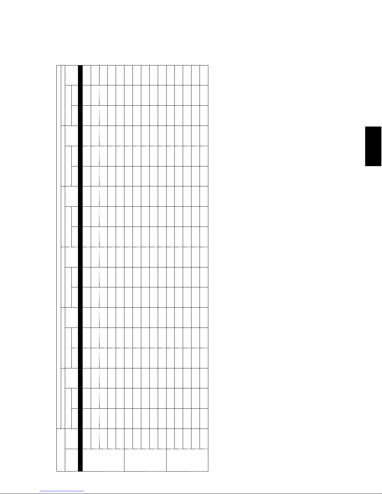
PERFORMANCE DATA
574D----A24
CFM/BF
700/0.07
EVAPORATOR AIR
800/0.09
900/0.1
See Legend and Notes on Page 19.
13
KW
Sys
Tot a l
Capacity MBtuh
KW
Sys
Tot a l
574D-- --A
Capacity MBtuh
KW
Sys
Tot a l
Capacity MBtuh
CONDEN SER ENTER ING AIR TEMPERATURES _F(_C)
Tot a l
Tot a l
Tot a l
75 (23.9) 85 (29.4) 95 (35) 105 (40.6) 115 (46.1) 125 (51.7)
EWB
Capacity MBtuh
Capacity MBtuh
Capacity MBtuh
KW
Sys
KW
Sys
KW
Sys
Tot a l Sens To t a l Sens To tal Sens To t a l Sens To t a l Sens Tot a l Sens
29.20 29.20 2.09 27.20 27.20 2.30 25.19 25.19 2.52 23.18 23.18 2.77 21.16 21.16 3.04 19.13 19.13 3.32
30.09 26.44 2.09 27.78 25.28 2.30 25.48 24.10 2.52 23.22 23.12 2.77 21.16 21.16 3.04 19.12 19.12 3.32
30.75 21.65 2.09 28.36 20.61 2.30 25.99 19.56 2.52 23.63 18.51 2.77 21.26 17.45 3.04 18.90 16.38 3.32
33.12 22.39 2.08 30.58 21.34 2.29 28.05 20.29 2.52 25.52 19.23 2.77 23.00 18.16 3.04 20.48 17.08 3.32
36.50 18.28 2.08 33.73 17.33 2.29 30.97 16.37 2.52 28.22 15.41 2.77 25.48 14.44 3.04 22.73 13.46 3.32
30.51 30.51 2.12 28.39 28.39 2.33 26.27 26.27 2.56 24.14 24.14 2.80 22.01 22.01 3.07 19.87 19.87 3.35
30.85 28.45 2.12 28.49 28.24 2.33 26.26 26.26 2.56 24.14 24.14 2.80 22.01 22.01 3.07 19.86 19.86 3.35
31.44 23.11 2.12 28.97 22.02 2.33 26.51 20.93 2.56 24.07 19.84 2.81 21.63 18.73 3.07 19.21 17.60 3.35
33.86 23.94 2.12 31.22 22.85 2.33 28.60 21.75 2.55 25.99 20.65 2.80 23.40 19.53 3.07 20.80 18.40 3.35
37.30 19.27 2.11 34.43 18.29 2.32 31.58 17.30 2.55 28.74 16.31 2.80 25.91 15.31 3.07 23.07 14.29 3.35
31.61 31.61 2.15 29.39 29.39 2.36 27.17 27.17 2.59 24.95 24.95 2.84 22.72 22.72 3.10 20.48 20.48 3.39
31.61 31.61 2.15 29.39 29.39 2.36 27.17 27.17 2.59 24.95 24.95 2.84 22.72 22.72 3.10 20.48 20.48 3.39
31.97 24.51 2.15 29.43 23.38 2.36 26.91 22.25 2.59 24.41 21.10 2.84 21.92 19.95 3.10 19.45 18.75 3.39
34.42 25.44 2.15 31.71 24.30 2.36 29.02 23.16 2.59 26.35 22.01 2.84 23.69 20.84 3.10 21.05 19.65 3.39
37.91 20.22 2.14 34.96 19.20 2.35 32.03 18.19 2.58 29.12 17.17 2.83 26.22 16.14 3.10 23.32 15.10 3.39
_F
57
62
67
72
57
62
67
72
57
62
67
(_C)
63*
(13.8)
(16.6)
(19.4)
(22.2)
(17.2)
63*
(13.8)
(16.6)
(19.4)
(22.2)
(13.8)
(17.2)
(16.6)
63*
72
(19.4)
(22.2)
(17.2)
EVAPORATOR AIR
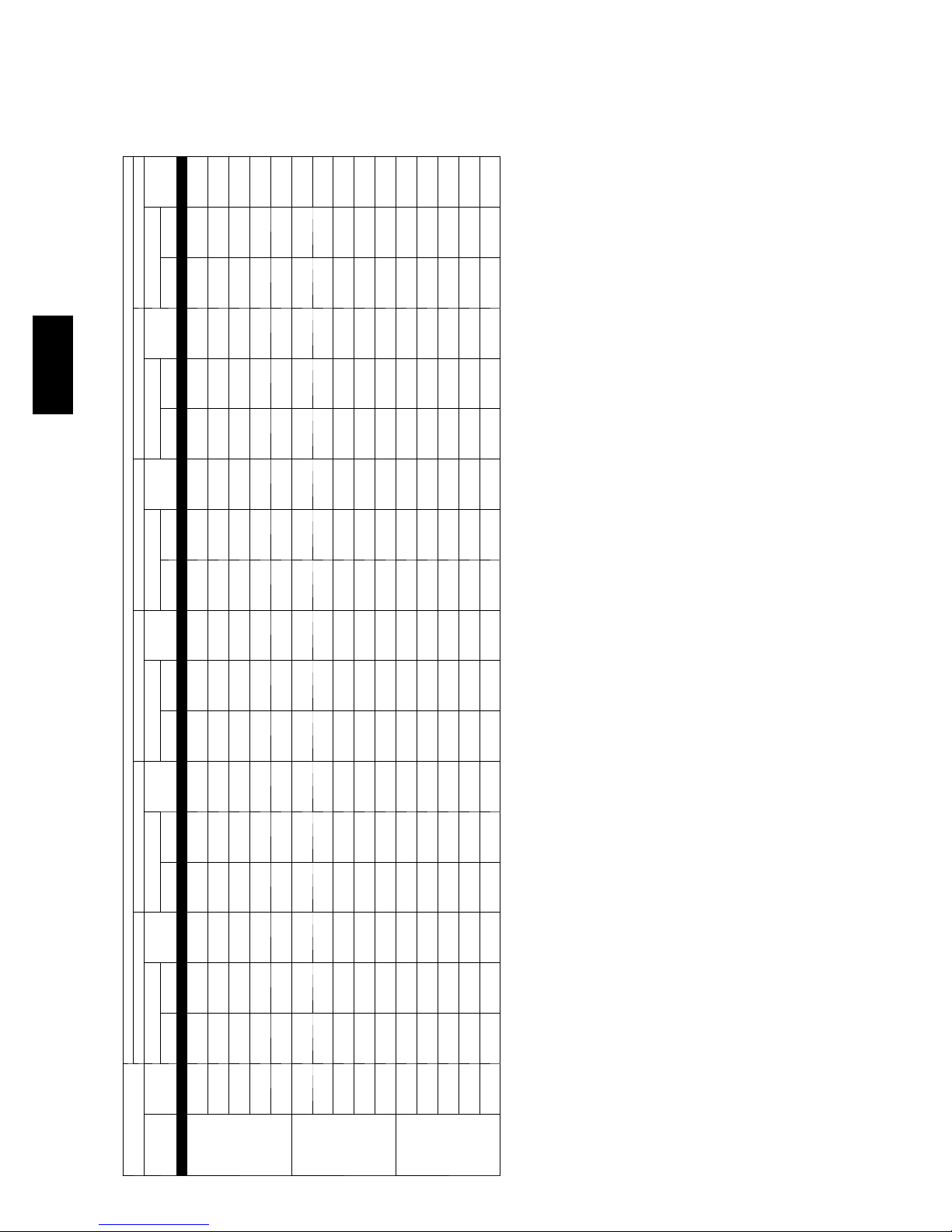
PERFORMANCE DATA
574D----A30
CFM/BF
875/0.03
1000/0.03
1125/0.04
See Legend and Notes on Page 19.
14
KW
Sys
Tot a l
Capacity MBtuh
KW
Sys
Tot a l
574D-- --A
Capacity MBtuh
KW
Sys
Tot a l
Capacity MBtuh
CONDEN SER ENTER ING AIR TEMPERATURES _F(_C)
Tot a l
Tot a l
Tot a l
75 (23.9) 85 (29.4) 95 (35) 105 (40.6) 115 (46.1) 125 (51.7)
EWB
Capacity MBtuh
Capacity MBtuh
Capacity MBtuh
KW
Sys
KW
Sys
KW
Sys
Tot a l Sens To t a l Sens To tal Sens To t a l Sens To t a l Sens Tot a l Sens
35.66 35.66 2.38 32.84 32.84 2.71 30.06 30.06 3.07 27.32 27.32 3.47 24.62 24.62 3.91 21.93 21.93 4.39
37.06 32.25 2.39 33.82 30.46 2.71 30.65 28.68 3.07 27.56 26.88 3.47 24.62 24.62 3.91 21.93 21.93 4.39
37.87 26.52 2.39 34.55 24.93 2.71 31.28 23.37 3.08 28.09 21.82 3.48 24.95 20.29 3.91 21.88 18.77 4.39
40.79 27.41 2.39 37.23 25.80 2.72 33.74 24.21 3.08 30.32 22.64 3.48 26.96 21.09 3.92 23.65 19.54 4.39
44.91 22.49 2.39 41.02 21.04 2.72 37.19 19.62 3.09 33.45 18.21 3.49 29.78 16.82 3.93 26.16 15.44 4.40
37.24 37.24 2.43 34.27 34.27 2.76 31.33 31.33 3.12 28.44 28.44 3.52 25.58 25.58 3.96 22.76 22.76 4.44
37.97 34.65 2.43 34.64 32.72 2.76 31.35 31.35 3.12 28.43 28.43 3.52 25.58 25.58 3.96 22.75 22.75 4.44
38.73 28.25 2.43 35.29 26.59 2.76 31.91 24.95 3.12 28.60 23.33 3.52 25.37 21.73 3.96 22.21 20.12 4.44
41.71 29.24 2.44 38.02 27.56 2.76 34.40 25.90 3.13 30.86 24.26 3.53 27.40 22.63 3.97 24.00 21.00 4.44
45.90 23.65 2.44 41.86 22.16 2.77 37.91 20.68 3.13 34.05 19.23 3.54 30.26 17.79 3.98 26.53 16.36 4.45
38.59 38.59 2.48 35.47 35.47 2.81 32.40 32.40 3.17 29.37 29.37 3.57 26.39 26.39 4.01 23.43 23.43 4.49
38.77 36.79 2.48 35.46 35.46 2.81 32.39 32.39 3.17 29.37 29.37 3.57 26.38 26.38 4.01 23.43 23.43 4.49
39.40 29.91 2.48 35.85 28.18 2.81 32.38 26.47 3.17 28.99 24.78 3.57 25.69 23.09 4.01 22.46 21.40 4.49
42.41 31.01 2.48 38.61 29.26 2.81 34.89 27.52 3.18 31.27 25.81 3.58 27.72 24.10 4.02 24.26 22.39 4.49
46.65 24.77 2.49 42.51 23.22 2.82 38.45 21.70 3.18 34.49 20.20 3.58 30.61 18.72 4.03 26.80 17.24 4.50
_F
57
62
67
72
57
62
67
72
57
62
67
(_C)
63*
(13.8)
(16.6)
(19.4)
(22.2)
(17.2)
63*
(13.8)
(16.6)
(19.4)
(22.2)
(13.8)
(17.2)
(16.6)
63*
72
(19.4)
(22.2)
(17.2)
PERFORMANCE DATA
574D----A36
CFM/BF
1050/0.04
EVAPORATOR AIR
1200/0.04
1350/0.05
See Legend and Notes on Page 19.
15
KW
Sys
Tot a l
Capacity MBtuh
KW
Sys
Tot a l
574D-- --A
Capacity MBtuh
KW
Sys
Tot a l
Capacity MBtuh
CONDEN SER ENTER ING AIR TEMPERATURES _F(_C)
Tot a l
Tot a l
Tot a l
75 (23.9) 85 (29.4) 95 (35) 105 (40.6) 115 (46.1) 125 (51.7)
Capacity MBtuh
Capacity MBtuh
Capacity MBtuh
KW
Sys
KW
Sys
KW
Sys
Tot a l Sens To t a l Sens To tal Sens To t a l Sens To t a l Sens Tot a l Sens
40.45 40.45 3.00 37.98 37.98 3.37 35.49 35.49 3.78 32.98 32.98 4.20 30.44 30.44 4.65 27.84 27.84 5.10
42.06 37.63 2.94 39.15 35.73 3.33 36.25 33.83 3.74 33.37 31.92 4.18 30.48 30.39 4.64 27.88 27.88 5.10
42.93 30.96 2.91 39.95 29.27 3.31 36.96 27.59 3.72 33.97 25.92 4.17 30.95 24.26 4.63 27.90 22.59 5.10
46.12 31.94 2.80 42.92 30.23 3.19 39.72 28.52 3.61 36.53 26.83 4.05 33.31 25.15 4.52 30.04 23.46 4.99
50.58 26.16 2.65 47.09 24.61 3.04 43.59 23.08 3.46 40.11 21.56 3.90 36.60 20.05 4.37 33.04 18.53 4.84
42.24 42.24 2.98 39.61 39.61 3.35 36.97 36.97 3.76 34.32 34.32 4.18 31.63 31.63 4.63 28.88 28.88 5.08
43.11 40.44 2.95 40.11 38.38 3.34 37.15 36.28 3.75 34.31 34.31 4.18 31.62 31.62 4.63 28.88 28.88 5.08
43.91 32.97 2.92 40.81 31.21 3.32 37.71 29.45 3.73 34.61 27.70 4.18 31.49 25.96 4.64 28.35 24.21 5.12
47.15 34.07 2.81 43.82 32.28 3.20 40.50 30.50 3.62 37.19 28.73 4.06 33.86 26.97 4.53 30.50 25.20 5.00
51.67 27.51 2.65 48.05 25.91 3.05 44.42 24.32 3.46 40.81 22.75 3.91 37.19 21.19 4.38 33.51 19.62 4.85
43.75 43.75 2.97 40.99 40.99 3.34 38.22 38.22 3.75 35.43 35.43 4.17 32.62 32.62 4.62 29.74 29.74 5.07
44.02 42.95 2.96 41.01 41.01 3.34 38.21 38.21 3.75 35.43 35.43 4.17 32.61 32.61 4.62 29.74 29.74 5.07
44.67 34.90 2.94 41.47 33.06 3.33 38.28 31.23 3.75 35.10 29.41 4.20 31.91 27.58 4.66 28.70 25.74 5.14
47.93 36.13 2.82 44.51 34.26 3.21 41.09 32.40 3.63 37.69 30.56 4.08 34.28 28.71 4.54 30.85 26.85 5.02
52.51 28.80 2.67 48.78 27.15 3.06 45.05 25.51 3.48 41.34 23.89 3.93 37.63 22.28 4.39 33.86 20.67 4.87
57
62
67
72
57
62
67
72
57
62
67
63*
(13.8)
(16.6)
(19.4)
(22.2)
(17.2)
63*
(13.8)
(16.6)
(19.4)
(22.2)
(13.8)
(17.2)
(16.6)
63*
72
(19.4)
(22.2)
(17.2)
PERFORMANCE DATA
EVAPORATOR AIR
574D----A42
1225/0.03
CFM/BF EWB
1400/0.04
1575/0.05
See Legend and Notes on Page 19.
16

KW
Sys
Capacity MBtuh To t a l
KW
Sys
Tot a l
Sens To t a l Sens
Capacity MBtuh
KW
Sys
Tot a l
Capacity MBtuh
KW
Sys
Tot a l
CONDEN SER ENTER ING AIR TEMPERATURES _F(_C)
Capacity MBtuh
KW
Sys
Tot a l
574D-- --A
Capacity MBtuh
KW
Sys
Tot a l
75 (23.9) 85 (29.4) 95 (35) 105 (40.6) 115 (46.1) 125 (51.7)
Capacity MBtuh
Tot a l Sens To t a l Sens To tal Sens To t a l Sens To t a l
46.51 46.51 3.29 43.60 43.60 3.68 40.66 40.66 4.11 37.70 37.70 4.56 34.70 34.70 5.05 31.64 31.64 5.55
48.43 41.91 3.29 45.02 40.09 3.68 41.60 38.24 4.10 38.19 36.35 4.56 34.81 34.56 5.05 31.64 31.64 5.55
49.45 34.51 3.29 45.95 32.87 3.68 42.43 31.22 4.10 38.89 29.56 4.56 35.34 27.89 5.05 31.75 26.19 5.55
53.14 35.61 3.29 49.39 33.95 3.68 45.62 32.29 4.10 41.85 30.61 4.55 38.05 28.93 5.04 34.20 27.21 5.55
58.33 29.19 3.28 54.23 27.68 3.67 50.11 26.15 4.09 46.00 24.62 4.55 41.85 23.08 5.03 37.64 21.51 5.54
57
62
67
72
57
(19.4)
(22.2)
PERFORMANCE DATA
EVAPORATOR AIR
574D----A48
EWB
_F
(_C)
CFMBF
63*
(13.8)
(16.6)
(17.2)
1400/0.04
48.55 48.55 3.35 45.46 45.46 3.74 42.35 42.35 4.16 39.21 39.21 4.61 36.04 36.04 5.10 32.81 32.81 5.60
49.62 44.99 3.35 46.10 43.02 3.74 42.60 40.97 4.16 39.21 39.21 4.61 36.04 36.04 5.10 32.80 32.80 5.60
50.57 36.73 3.35 46.92 35.02 3.74 43.27 33.30 4.16 39.61 31.57 4.61 35.94 29.83 5.10 32.24 28.05 5.60
54.31 37.96 3.34 50.41 36.23 3.73 46.50 34.50 4.15 42.59 32.76 4.61 38.66 30.99 5.09 34.70 29.20 5.60
59.58 30.68 3.34 55.32 29.12 3.73 51.05 27.54 4.15 46.80 25.97 4.60 42.51 24.38 5.08 38.17 22.76 5.59
50.26 50.26 3.40 47.02 47.02 3.79 43.76 43.76 4.21 40.47 40.47 4.66 37.15 37.15 5.15 33.76 33.76 5.65
50.64 47.75 3.40 47.06 47.06 3.79 43.75 43.75 4.21 40.46 40.46 4.66 37.14 37.14 5.15 33.76 33.76 5.65
51.44 38.88 3.40 47.67 37.10 3.79 43.92 35.31 4.21 40.16 33.51 4.67 36.40 31.68 5.15 32.62 29.81 5.66
55.22 40.25 3.40 51.19 38.45 3.79 47.17 36.64 4.21 43.16 34.83 4.66 39.13 32.98 5.14 35.08 31.10 5.65
60.54 32.12 3.40 56.16 30.51 3.78 51.77 28.89 4.20 47.40 27.27 4.65 43.00 25.64 5.13 38.55 23.98 5.64
62
67
72
57
62
67
63*
(13.8)
(16.6)
(19.4)
(22.2)
(13.8)
(17.2)
1600/0.05
(16.6)
63*
72
(19.4)
(22.2)
(17.2)
1800/0.06
See Legend and Notes on Page 19.
17
 Loading...