

Bryant 569J Series Installation, Start-up And Service Instructions Manual
569J
AIR--COOLED CONDENSING UNITS
60 Hz, with PURONR(R--410A) REFRIGERANT
SIZES 07--14
Installation, Start--Up and
Service Instructions
TABLE OF CONTENTS
SAFETY CONSIDERATIONS 2....................
INSTALLATION GUIDELINES 2..................
Replacement/Retrofit — R--22 to Puron 2...........
Rated Indoor Airflow (cfm) 3.....................
Matching 569J Model to Evaporator Coil 10.........
INSTALLATION 10 -- 26.........................
Jobsite Survey 10...............................
Step 1 -- Plan for Unit Location 10.................
Step 2 -- Complete Pre--Installation Checks 10........
Step 3 -- Prepare Unit Mounting Support 11..........
Step 4 -- Rig and Mount the Unit 11................
Step 5 -- Determine Refrigerant Line Sizes 11........
Step 6 -- Complete Refrigerant Piping Connections 16...
Step 7 -- Install Accessories 19....................
Step 8 -- Complete Electrical Connections 19.........
Step 9 -- Wind Baffles for Low Ambient Controls 26...
PRE-START-UP 26...............................
System Check 26...............................
Turn On Crankcase Heater 26.....................
Preliminary Charge 26...........................
START--UP 26 -- 36..............................
Preliminary Checks 26...........................
Start Unit 27...................................
OPERATING SEQUENCE 37......................
Base Unit Controls 37...........................
Indoor (Supply) Fan 37..........................
Cooling, Unit Without Economizer 37..............
569J*12F, Unit with Hot Gas Bypass (HGBP) 37......
Cooling, Unit with Economizer 39.................
Heating 39....................................
ROUTINE SYSTEM MAINTENANCE 39............
Quarterly Inspection (and 30 days after initial start) 39...
Seasonal Maintenance 39........................
SERVICE 39 -- 47................................
Refrigeration System 39.........................
Compressor Oil 39..............................
Servicing Systems on Roofs with
Synthetic Materials 39...........................
Liquid Line Filter Drier 40.......................
Field Refrigerant Access Ports 40..................
Factory High--Flow Access Ports 40................
Hot Gas Bypass Valve Adjustments 40..............
Comfort Alert Diagnostic Module 41...............
Compressor Protection 43........................
Crankcase Heater 43............................
Low--Pressure Switch 43.........................
High--Pressure Switch 43.........................
Outdoor Fans 43................................
Lubrication 43.................................
Routine Cleaning of Round-Tube Plate Fin
(RTPF) Coils 46................................
Fastener Torque Values 47
TROUBLESHOOTING 47 -- 48.....................
APPENDIX A
Air Conditioner & Heat Pump with Puron
Quick Reference Guide 49.........................
APPENDIX B
Wiring Diagram List 49...........................
APPENDIX C
Low Ambient Option — Factory Installed 50..........
START--UP CHECKLIST 55 -- 56...................
........................
R
—
1
SAFETY CONSIDERATIONS
Improper installation, adjustment, alteration, service,
maintenance, or use can cause explosion, fire, electrical
shock or other conditions which may cause personal
injury or property damage. Consult a qualified installer,
service agency, or your distributor or branch for
information or assistance. The qualified installer or
agency must use factory-authorized kits or accessories
when modifying this product. Refer to the individual
instructions package
Follow all safety codes. Wear safety glasses and work
gloves. Use quenching cloths for brazing operations and
have a fire extinguisher available. Read these instructions
thoroughly and follow all warnings or cautions attached to
the unit. Consult local building codes and appropriate
national electrical codes (in USA, ANSI/NFPA70,
National Electrical Code (NEC); in Canada, CSA C22.1)
for special requirements.
569J
It is important to recognize safety information. This is the
safety--alert symbol
unit and in instructions or manuals, be alert to the
potential for personal injury.
Understand the signal words DANGER, WARNING,
CAUTION, and NOTE. These words are used with the
safety-alert symbol. DANGER identifies the most serious
hazards which will result in severe personal injury or
death. WARNING signifies hazards which could result in
personal injury or death. CAUTION is used to identify
unsafe practices, which may result in minor personal
injury or product and property damage. NOTE is used to
highlight suggestions which will result in enhanced
installation, reliability, or operation.
!
ELECTRICAL SHOCK HAZARD
Failure to follow this warning could cause personal
injury or death.
Before performing service or maintenance operations
on unit, turn off main power switch to unit and install
lock(s) and lockout tag(s). Ensure electrical service to
rooftop unit agrees with voltage and amperage listed
on the unit rating plate. Unit may have more than one
power switch.
!
UNIT OPERATION AND SAFETY HAZARD
Failure to follow this warning could cause in personal
injury,death and/or equipment damage.
R
Puron
higher pressures than standard R--22 systems. Do not
use R--22 service equipment or components on Puron
refrigerant equipment.
(R--410A) refrigerant systems operate at
. When you see this symbol on the
WARNING
WARNING
!
WARNING
PERSONAL INJURY AND ENVIRONMENTAL
HAZARD
Failure to follow this warning could cause in personal
injury or death.
Relieve pressure and recover all refrigerant before
system repair or final unit disposal.
Wear safety glasses and gloves when handling
refrigerants. Keep torches and other ignition sources
away from refrigerants and oils.
!
CAUTION
CUT HAZARD
Failure to follow this caution may result in personal
injury.
Sheet metal parts may have sharp edges or burrs. Use
care and wear appropriate protective clothing, safety
glasses and gloves when handling parts and servicing
569J units.
INSTALLATION GUIDELINE
Replacement/Retrofit — R--22 to Puron
Replacement/retrofit installations require change-out of
outdoor unit, metering device, and filter driers.
Change-out of indoor coil (evaporator) and
interconnecting tubing is recommended.
Existing evaporator coil – If the existing evaporator coil
may be re-used, check with the coil manufacturer to verify
the coil construction is suitable for operation with the
higher pressures of Puron
the existing TXV valve is compatible with R-410A,
replace if necessary. The minimum factory test pressure
rating must be 250 psig (1725 kPa). Existing coil will
need to be purged with Nitrogen to remove as much
mineral oil as possible to eliminate cross contamination of
oils.
Acid test – If the existing system is being replaced
because of a compressor electrical failure, assume acid is
in system. If system is being replaced for any other
reason, use an approved acid test kit to determine acid
level. If even low levels of acid are detected, install a 100
percent activated alumina suction-line filter drier in
addition to the replacement liquid-line filter drier.
Remove the suction line filter drier as soon as possible,
with a maximum of 72 hr of operation. Recommendation:
Install a ball valve in the liquid line at the filter drier
location when installing a suction filter in the suction line.
Existing refrigeration piping – Reuse of existing refrigerant
piping involves three issues: quality (strength) of existing
tubing, cleanliness and tube size. Inspect all tube segments
and joints for signs of damage, corrosion or poor brazing.
Flush the interconnecting piping system with dry Nitrogen to
eliminate as much trace of mineral oil as possible.
R
(R-410A). Also determine if
R
2
Same tube sizes are capable of handling higher flowrates
(expressed as tons of cooling capacity) with Puron
refrigerant compared to R--22 at constant pressure drops.
1
For example, a
higher tons with Puron
drop). A 1
/2--inch OD liquid line is rated at 33%
R
1
/8--inch OD suction line is rated at 53% higher
than with R--22 (at 5_F pressure
tons with Puron than with R--22 (at 2_F pressure drop).
Refrigeration lines selected for R--22 use are typically
oversized for Puron applications. Carefully check the
existing suction line size against the table for maximum size
(see Table 8); replace vertical riser segments if necessary.
Check existing liquid line size against sizing data in Table 5
or 6; replace with smaller lines when feasible.
Installation –
1. Remove the existing evaporator coil or fan coil and
install the replacement coil when appropriate.
2. Drain oil from low points and traps in suction line
tubing (and hot gas bypass tubing if appropriate) and
evaporator if they were not replaced. Removing oil
from evaporator coil may require purging of the
tubing with dry nitrogen.
3. Unless indoor unit is equipped with a Puron
approved metering device, change the metering
device to a thermal expansion valve (TXV) designed
for Puron
R
(R-410A).
4. Remove the existing outdoor unit. Install the new outdoor unit according to these installation instructions.
5. Install a new field-supplied liquid-line filter drier at
the indoor coil just upstream of the TXV or fix orifice
metering device.
6. If a suction line filter drier is also to be installed, install suction line drier downstream of suction line service valve at condensing unit.
!
CAUTION
7. If required, install a 100% activated alumina suction
line filter drier at the outdoor unit.
8. Evacuate and charge the system according to the instructions in this installation manual.
9. Operate the system for 10 hr. Monitor the pressure
drop across the suction line filter drier. If pressure
drop exceeds 3 psig (21kPa), replace suction-line and
liquid-line filter driers. Be sure to purge system with
dry nitrogen and evacuate when replacing filter
driers. Continue to monitor the pressure drop across
suction-line filter drier. Repeat filter changes if necessary. Never leave suction-line filter drier in system
longer than 72 hr (actual time).
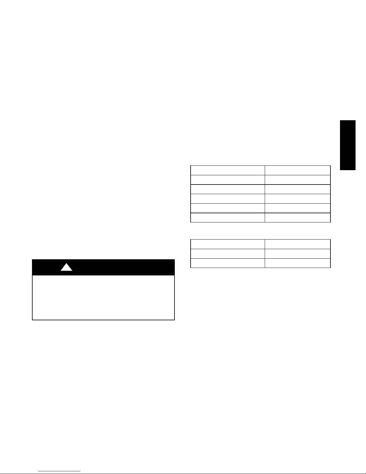
Rated Indoor Airflow (cfm)
The table below lists the rated indoor airflow used for the
AHRI efficiency rating for the units covered in this
document.
569J
569J***A/B/G/H with 524J***A
Model Numbers Full Load Airflow (cfm)
569J*07A/B --- 524J*07A 2400
569J*07G/H --- 524J*07A 2625
569J*08A/B --- 524J*08A 3000
569J*12A/B --- 524J*12A 4000
569J*14A/B --- 524J*14A 4375
569J***D/E/F with 524J***A
Model Numbers Full Load Airflow (cfm)
569J*12D/E/F --- 524J*12A 4000
569J*14D/E --- 524J*14A 4400
UNIT DAMAGE HAZARD
Failure to follow this caution may result in equipment
damage or improper operation.
Never install suction--line filter drier in the liquid--line
of a Puron
R
system.
3
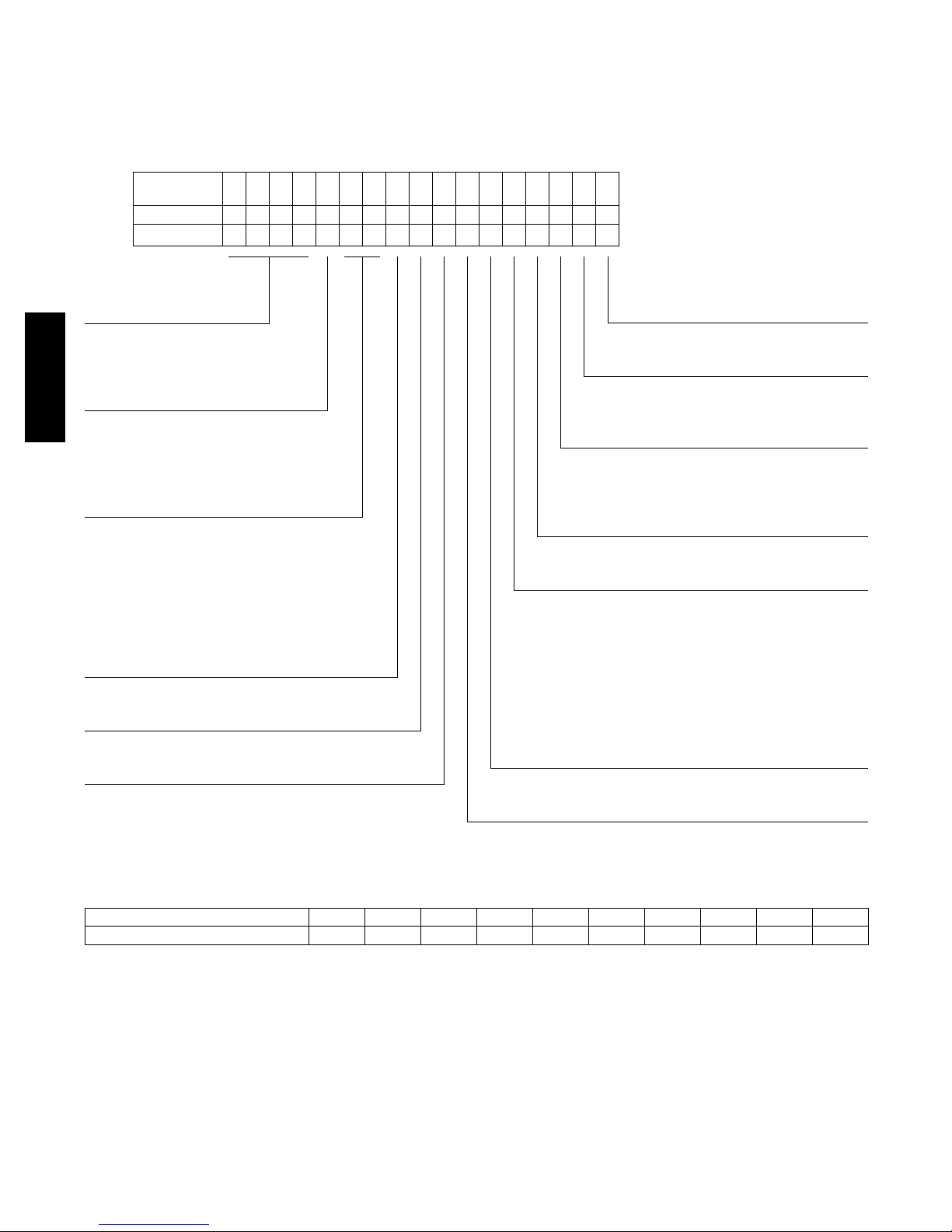
Identify Factory Options —
Factory options will affect 569J unit pipe sizing selections.
Coil type impacts liquid lift limits; Hot Gas Bypass impacts
the selection of suction tube size in vertical riser segments.
Check this unit’s Model Number against the Model Number
Nomenclature, Fig. 1. Determine the significance of this
Enter this unit’s
Model Number
Position
Example
1 2 3 4 5 6 7 8 9 10 11 12 13 14 15 16 17
569JE12F000A00A0A
unit’s values in Position 9 (Coil type) and Position 6 (Hot
Gas Bypass, 569J*12F only). Copy the unit’s Model Number
from the unit’s dataplate into the open line in the header
above Fig. 1 to facilitate this step.
Model Type
569J = Bryant Condensing Unit
®
R–410A Refrigerant
Puron
Voltage
E = 460/3/60
P = 208 / 230/3/6
569J
T = 575/3/60
Nominal Tonnage
07 = 6 Tons
08 = 7.5 Tons
12 = 10 Tons
14 = 12.5 Tons
Refrigerant Circuit
A = Single Circuit
B = Single Circuit with Low Ambient Controller
D = Dual Circuit
E = Dual Circuit with Low Ambient Controller
F = Dual Circuit with Hot Gas Bypass (569J* size 12 only)
G = Single Circuit, Two Stage
H = Single Circuit, Two Stage with Low Ambient Controller
Not Used
0 = Not Used
Not Used
0 = Not Used
Packaging
A=Standard
B=LTL
Base Unit Controls
0 = Electro-Mechanical Controls
Electrical Options
A = None
C = Non-Fused Disconnect
Service Options
0 = None
1 = Unpowered Convenience Outlet
2 = Powered Convenience Outlet
Not Used
0 = Not Used
CoilOptions
RTPF
A = Al/Cu Standard
B = Pre Coated Al/Cu
C = E-Coated Al/Cu
E = Cu/CuM=Al/Cu Standard with Louvered Hail Guard
N = Pre Coated Al/Cu with Louvered Hail Guard
P = E-Coated Al/Cu with Louvered Hail Guard
R = Cu/Cu with Louvered Hail Guard
Not Used
0 = Not Used
C150349
Fig. 1 -- Model Number Nomenclature
POSITION NUMBER
TYPICAL
12345678910
0515C12345
DESIGNATESPOSITION
1−2
3−4
Week of manufacture (fiscal calander)
Year of manufacture (”15” = 2015)
Manufacturing location5
6−10
Sequence number
C150336
Fig. 2 -- Serial Number Nomenclature
4
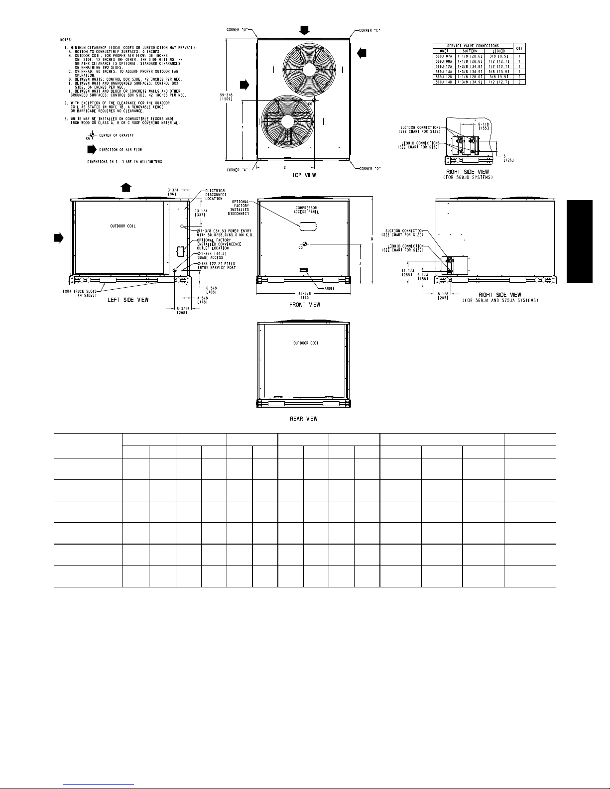
UNIT
569J*07A/B/G/ H
(RTPF)
569J*08A/B
(RTPF)
569J*12A/B
(RTPF)
569J*14A/B
(RTPF)
569J*12D/E/F
(RTPF)
569J*14D/E/
(RTPF)
LEGEND: RTPF = Round Tube/Plate Fin coil
STD. UNIT WT. CORNER A CORNER B CORNER C CORNER D CENTER OF GRAVITY UNIT HEIGHT
lbs. kg. lbs. kg. lbs. kg. lbs. kg. lbs. kg. X Y Z H
389 176 141 64 96 44 62 28 91 41
391 177 142 64 96 44 62 28 91 41
490 222 177 80 120 54 78 35 114 52
598 271 195 88 142 64 110 50 151 68
516 234 185 84 117 53 83 38 131 59
654 297 214 97 155 70 120 54 165 75
Fig. 3 -- 569J Unit Dimensions
18
[457.2]24[609.6]21[533.4]
18
[457.2]24[609.6]21[533.4]
18
[457.2]24[609.6]24[609.6]
20
[508.0]25[635.0]24[609.6]
19
[482.6]23[584.2]24[609.6]
20
[508.0]25[635.0]24[609.6]
C150350
423/
8
[1076.0]
423/
8
[1076.0]
503/
8
[1279.2]
503/
8
[1279.2]
503/
8
[1279.2]
503/
8
[1279.2]
569J
5
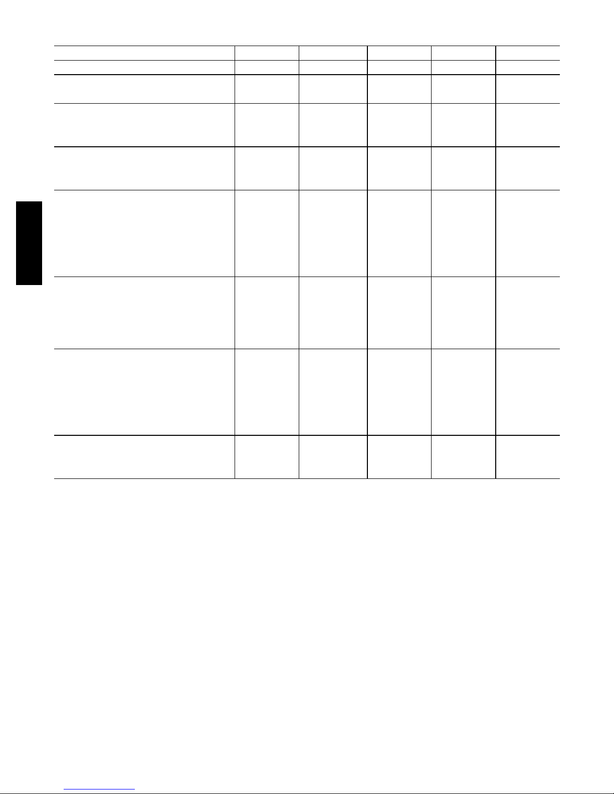
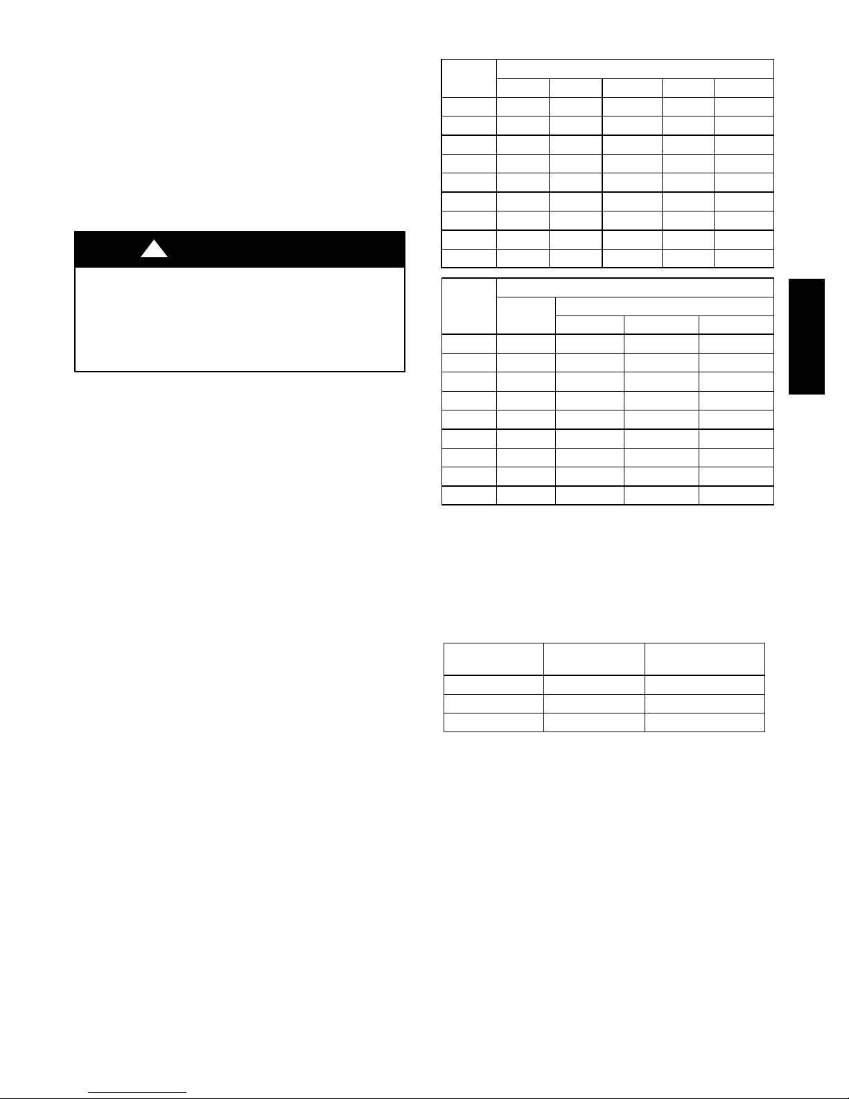
Table 1A — Physical Data — 569J*07-14A/B/G/H Units — 60 Hz English
UNIT 569J*07A/B 569J*07G/H 569J*08A/B 569J*12A/B 569J*14A/B
NOMINAL CAPACITY (tons) 6 6 7.5 10 12.5
OPERATING WEIGHTS (lb)
Round Tube/Plate Fin Coil (Cu/Al) 389 389 391 490 598
REFRIGERANT TYPE
Operating Charge (w/ fan coil), Typical (lb)
Shipping Charge (lb) 9.0 9.0 9.0 9.0 9.0
COMPRESSOR
Qty...Type 1...Scroll 1...2 Stage Scroll 1...Scroll 1...Scroll 1...Scroll
Oil Charge (oz) 56 56 60 110 110
CONDENSER FANS
Qty...Rpm 2...1100 2...1100 2...1100 2...1100 2...1100
Motor Hp
Diameter 22 22 22 22 22
569J
Nominal Airflow (Cfm Total) 6000 6000 6000 6000 6000
Watts (Total) 610 610 610 610 610
RTPF CONDENSER COIL
Material (Tube/Fin) Cu / Al Cu / Al Cu / Al Cu / Al Cu / Al
Coil Type
Rows/Fins per inch (FPI) 2/17 2/17 2/17 2/17 3/17
Face Area (sq ft total) 17.5 17.5 17.5 25.1 31.8
CONTROLS
Pressurestat Settings (psig)
High Cutout 630 10 630 10 630 10 630 10 630 10
Cut-in 505 20 505 20 505 20 505 20 505 20
Low Cutout 54 3 54 3 54 3 54 3 54 3
Cut-in 117 5 117 5 117 5 117 5 117 5
PIPING CONNECTIONS (in. ODS)
Qty...Suction 1...11/
Qty...Liquid 1...3/
LEGEND
RTPF — Round Tube/Plate Fin
ODS — Outside Diameter Sweat (socket)
‡
Unit is factory-supplied with partial charge only.
†
Typical operating charge with 25 ft of interconn ecting pipin g.
‡
R-410A R-410A R-410A R-410A R-410A
†
14.0 14.0 17.0 20.0 43.0
1
/
4
3
/8--- i n R TP F
8
8
1
/
4
3
/8--- i n R TP F
1...11/
1...3/
1
/
4
3
/8--- i n R TP F
8
8
1...11/
1...1/
8
2
1
/
4
3
/8--- i n R TP F
1...13/
1...1/
8
2
1
/
4
3
/8--- i n R TP F
1...13/
1...5/
8
8
6
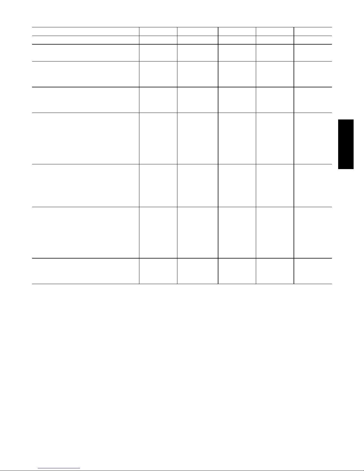
Table 1B — Physical Data — 569J*07-14A/B/G/H Units — 60 Hz SI
UNIT 569J*07A/B 569J*07G/H 569J*08A/B 569J*12A/B 569J*14A/B
NOMINAL CAPACITY (kW) 21.1 21.1 26.4 35.1 44
OPERATING WEIGHTS (lb )
Round Tube / P late Fin Coil (Cu/Al) 176 176 177 222 271
REFRIGERANT TYPE
Operating Charge (w/ fan coil), T yp i c al (kg )
Shipping Charge (kg) 4.1 4.1 4.1 4.1 4.1
COMPRESSOR
Qty...T ype 1...Scroll 1...2 Stage Scroll 1...Scroll 1...Scroll 1...Scroll
Oil Charge (oz) 1.7 1.7 1.8 3.3 3.3
CONDENS ER FANS
Qty...r/s 2...18 2...18 2...18 2...18 2...18
Motor Hp NEMA
Diameter (mm) 560 560 560 560 560
Nominal Airflow (L/s) 2832 2832 2832 2832 2832
Watts (T otal) 610 610 610 610 610
RTPF CONDENSER COIL
Material (T ub e/ Fin) Cu / Al Cu / Al Cu / Al Cu / Al Cu / Al
Coil Type
Rows/Fins per Meter (Fins/m) 2 / 670 2 / 670 2 / 670 2 / 670 3 / 670
Face Area (sq m total) 1.6 1.6 1.6 2.3 3.0
CONTROLS
Pressurestat Settings (kPa)
High Cutout 4347 70 4347 70 4347 70 4347 70 4347 70
Cut-in 3482 138 3482 138 3482 138 3482 138 3482 138
Low Cutout 372 21 372 21 372 21 372 21 372 21
Cut-in 807 34 807 34 807 34 807 34 807 34
PIPING CONNECTIONS (in. ODS)
Qty...Suction 1...11/
Qty...Liquid 1...3/
LEGEND
RTPF — Round Tube/Plate Fin
NEMA — National Electrical Manufacturers Association
ODS — Outside Diameter Sweat (socket)
‡
Unit is factory-supplied with partial charge only.
†
Typical operating charge with 25 ft of interconn ecting pipin g.
‡
†
R-410A R-410A R-410A R-410A R-410A
6.4 6.4 7.7 9.1 19.5
1
/
4
3
/8--- i n R TP F
8
8
1
/
4
3
/8--- i n R TP F
1...11/
1...3/
1
/
4
3
/8--- i n R TP F
8
8
1...11/
1...1/
8
2
1
/
4
3
/8--- i n R TP F
1...13/
1...1/
3
/8--- i n R TP F
8
2
1...13/
1
1...5/
/
4
8
8
569J
7
569J
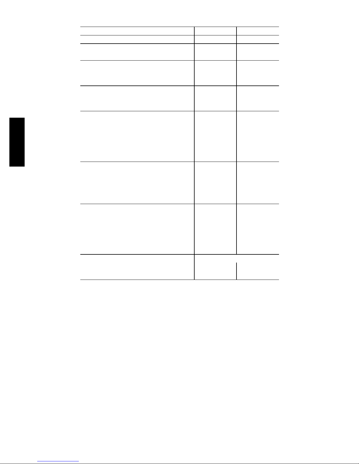
Table 2A — Physical Data — 569J*12-14D/E/F Units — 60 Hz English
UNIT 569J*12D/E/F 569J*14D/E
NOMINAL CAPACITY (tons) 10 12.5
OPERATING WEIGHTS (lb)
Round Tube/Plate Fin Coil (Cu/Al) 516 654
REFRIGERANT TYPE
Operati ng Charge 1/2 (w/ fan coil), T y p i c al (lb )
Shipping Charge 1/2 (lb) 9.0 / 9.0 9.0/9.0
COMPRESSOR
Qty...Type 2...Scroll 2...Scroll
Oil Charge 1/2 (oz) 42 60
CONDENSER FANS
Qty...Rpm 2...1100 2...1100
Motor Hp
Diameter 22 22
Nominal Airflow (Cfm Total) 6000 6000
Watts (Total) 610 610
RTPF CONDENSER COIL
Material (Tube/Fin) Cu / Al Cu / Al
Coil Type
Rows/Fins per inch (FPI) 2/17 3/17
Face Area (sq ft total) 25.1 31.8
CONTROLS
Pressurestat Settings (psig)
High Cutout 630 10 630 10
Cut-in 505 20 505 20
Low Cutout 54 3 54 3
Cut-in 117 5 117 5
PIPING CONNECTIONS (in. ODS)
Qty...Suction 1/2 1...11/8/ 1...11/81...13/8/ 1...13/
Qty...Liquid 1/2 1...3/8/ 1...3/
LEGEND
RTPF — Round Tube/Plate Fin
ODS — Outside Diameter Sweat (socket)
‡
Unit is factory-supplied with partial charge only.
†
Typical operating charge with 25 ft of interconn ecting pipin g.
‡
†
R-410A R-410A
11.0 / 11.0 22.0/22.0
1
/
4
3
/8--- i n R TP F
8
1
/
4
3
/8--- i n R TP F
1...1/2/ 1...1/
8
2
8

Table 2B — Physical Data — 569J*12-14D/E/F Units — 60 Hz SI
UNIT 569J*12D/E/F 569J*14D/E
NOMINAL CAPACITY (kW) 35.1 44
OPERATING WEIGHTS (kg)
Round Tube/Plate Fin Coil (Cu/Al) 234 297
REFRIGERANT TYPE
Operati ng Charge 1/2 (w/ fan coil), T y p i c al (kg )
Shipping Charge 1/2 (kg) 4.1 / 4.1 4.1 / 4.1
COMPRESSOR
Qty...Type 2...Scroll 2...Scroll
Oil Charge 1/2 (L) 1.2 1.7
CONDENSER FANS
Qty...r/s 2...1100 2...1100
Motor Hp NEMA
Diameter (mm) 560 560
Nominal Airflow (Cfm Total) 6000 6000
Watts (Total) 610 610
RTPF CONDENSER COIL
Material (Tube/Fin) Cu / Al Cu / Al
Coil Type
Rows/Fins per Meter (Fins/m) 2 / 670 3 / 670
Face Area (sq m total) 2.3 3.0
CONTROLS
Pressurestat Settings (kPa)
High Cutout 4347 70 4347 70
Cut-in 3482 138 3482 138
Low Cutout 372 21 372 21
Cut-in 807 34 807 34
PIPING CONNECTIONS (in. ODS)
Qty...Suction 1/2 1...11/8/ 1...11/81...13/8/ 1...13/
Qty...Liquid 1/2 1...3/8/ 1...3/
LEGEND
RTPF — Round Tube/Plate Fin
NEMA — National Electrical Manufacturers Association
ODS — Outside Diameter Sweat (socket)
‡
Unit is factory-supplied with partial charge only.
†
Typical operating charge with 7.62 m of interconnecting piping.
‡
†
R-410A R-410A
5.0 / 5.0 10.0 / 10.0
1
/
4
3
/8--- i n R TP F
8
3
/8--- i n R TP F
1...1/2/ 1...1/
1
/
4
569J
8
2
9
Matching 569J Model to Evaporator Coil
The Model 569J***A/B/G/H is a single-circuit unit design,
requiring one set of refrigeration piping. This model can be
connected to an evaporator coil with one circuit or with two
circuits (by manifolding the evaporator connections into a
single piping system).
The Model 569J***D/E/F is a dual-circuit unit design that
requires two sets of refrigeration piping between the
outdoor unit and the evaporator coil (or coils). This model
can only be connected to an evaporator coil that has two
refrigeration circuits (or to two separate evaporator coils).
The Model 569J***D/E/F CANNOT be connected to a
single-circuit evaporator coil. The Model 569J***D/E/F
CANNOT be field-converted to a single-circuit design.
Table 3 – Evaporator Coil Connections
Evaporator Coil has Connect to Model Notes
569J
Single Circuit 569J***A/B/G/H
Two Circuits
569J***A/B/G/H
Or
569J***D/E/F
Before unpacking this new 569J model, compare the
evaporator coil design to the 569J model.
Manifold evaporator
circuits into single
piping system
Use two separate
piping systems
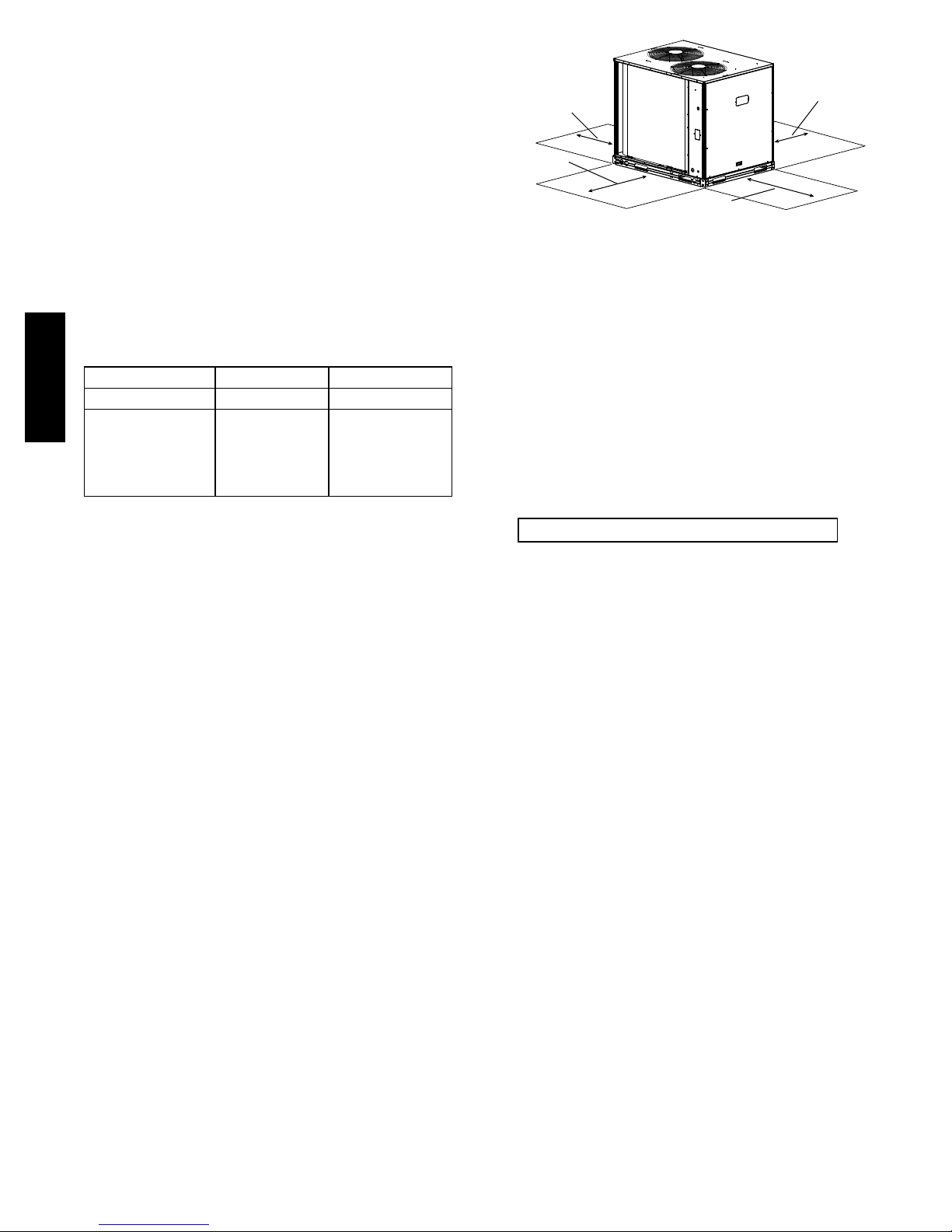
RIGHT:
REAR:
Min 18” (457 mm)
requried for service
LEFT:
Min 18” (457 mm)
requried for service
FRONT:
42” (1067 mm)
Note: Observe requirements for 39” (914 mm) operating clearance
on either Left or Rear coil opening.
requried for service
Min 18” (457 mm)
requried for service
C110201
Fig. 4 -- Service Clearance Dimensional Drawing
Do not install the outdoor unit in an area where fresh air
supply to the outdoor coil may be restricted or when
recirculation from the condenser fan discharge is possible.
Do not locate the unit in a well or next to high walls.
Evaluate the path and required line length for
interconnecting refrigeration piping, including suction
riser requirements (outdoor unit above indoor unit), liquid
line lift (outdoor unit below indoor unit) and hot gas
bypass line. Relocate sections to minimize the length of
interconnecting tubing.
DO NOT BURY REFRIGERATION LINES.
.INSTALLATION
Jobsite Survey
Complete the following checks before installation.
1. Consult local building codes and the NEC (National
Electrical Code) ANSI/NFPA 70 for special installation requirements.
2. Determine unit location (from project plans) or select
unit location.
3. Check for possible overhead obstructions which may
interfere with unit lifting or rigging.
Step 1 — Plan for Unit Location
The 569J units are designed and approved for outdoor
installation only. Do not locate these units indoors. Do not
add ducting to unit fan system.
Select a location for the unit and its support system (pad,
rails or other) that provides for the minimum clearances
required for safety. This includes the clearance to
combustible surfaces, unit performance and service access
below, around and above unit as specified in unit drawings.
See Fig. 4.
NOTE: Local codes may require different clearances
than specified in Fig. 4. It is the responsibility of installers
to be knowledgeable in local codes and to modify the
recommended clearances to satisfy local codes.
NOTE: Consider also the effect of adjacent units on
airflow performance and control box safety clearance.
Although unit is weatherproof, avoid locations that permit
water from higher level runoff and overhangs to fall onto
the unit.
Step 2 — Complete Pre-Installation Checks
Check Unit Electrical Characteristics: Confirm before
installation of unit that voltage, amperage and circuit
protection requirements listed on unit data plate agree with
power supply provided.
Un--crate Unit: Remove unit packaging except for the top
skid assembly, which should be left in place until after the
unit is rigged into its final location.
Inspect Shipment: File a claim with shipping company if
the shipment is damaged or incomplete.
Consider System Requirements:
S Consult local building codes and National Electrical Code
(NEC, U.S.A.) for special installation requirements.
S Allow sufficient space for airflow clearance, wiring,
refrigerant piping, and servicing unit. See Fig. 3 for unit
dimensions and weight distribution data.
S Locate the unit so that the outdoor coil (condenser)
airflow is unrestricted on all sides and above.
S The unit may be mounted on a level pad directly on the
base channels or mounted on raised pads at support
points. See Tables 1A through 2B for unit operating
weights. See Fig. 3 for weight distribution based on
recommended support points.
10
NOTE: If vibration isolators are required for a particular
installation, use the data in Fig. 3 to make the proper
selection.
Step 3 — Prepare Unit Mounting Support
Slab Mount —
Provide a level concrete slab that extends a minimum of 6
in. (150 mm) beyond unit cabinet. Install a gravel apron in
front of condenser coil air inlet to prevent grass and
foliage from obstructing airflow.
Step 4 — Rig and Mount the Unit
!
CAUTION
Table 4 – Equivalent Lengths for Common Fittings (ft)
Nominal
Tube OD
3
/
8
1
/
2
5
/
8
3
/
4
7/
8
11/
8
13/
8
15/
8
21/
8
90 Std 90 Lrad 90 Street 45 Std 45 Street
1.3 0.8 2.2 0.6 1
1.4 0.9 2.3 0.7 1.1
1.6 1 2.5 0.8 1.3
1.8 1.2 2.9 0.9 1.5
2 1.4 3.2 0.9 1.6
2.6 1.7 4.1 1.3 2.1
3.3 2.3 5.6 1.7 3
4 2.6 6.3 2.1 3.4
5 3.3 8.2 2.6 4.5
Elbows
UNIT DAMAGE HAZARD
Failure to follow this caution may result in equipment
damage.
All panels must be in place when rigging. Unit is not
designed for handling by fork truck.
Rigging: These units are designed for overhead rigging.
Refer to the rigging label for preferred rigging method.
Spreader bars are not required if top crating is left on the
unit. All panels must be in place when rigging. As further
protection for coil faces, plywood sheets may be placed
against the sides of the unit, behind cables. Run cables to
a central suspension point so that the angle from the
horizontal is not less than 45 degrees. Raise and set the
unit down carefully.
If it is necessary to roll the unit into position, mount the
unit on longitudinal rails, using a minimum of 3 rollers.
Apply force to the rails, not the unit. If the unit is to be
skidded into position, place it on a large pad and drag it
by the pad. Do not apply any force to the unit.
Raise from above to lift the unit from the rails or pad
when unit is in its final position.
After the unit is in position, remove all shipping materials
and top crating.
Step 5 — Determine Refrigerant Line Sizes
Select the recommended line sizes for 569J***A/B/G/H
and 569J***D/E/F unit from the appropriate tables.
Determine the linear length of interconnecting piping
required between the outdoor unit and indoor unit
(evaporator). Consider and identify also the arrangement
of the tubing path (quantity and type of elbows in both
lines), liquid line solenoid size, filter drier and any other
refrigeration specialties located in the liquid line. Refer to
the indoor unit installation instructions for additional
details on refrigeration specialties devices.
Determine equivalent line length adjustments for path and
components and add to linear line lengths. See Table 4,
Equivalent Lengths for Common Fittings, for usual fitting
types. Also identify adjustments for refrigeration
specialties. Contact Bryant Applications Engineering for
additional data and information on equivalent lengths.
Nominal
Tube OD
3
/
8
1
/
2
5
/
8
3
/
4
7/
8
11/
8
13/
8
15/
8
21/
8
Branch
Flow
2.6 0.8 1.1 1.3
2.7 0.9 1.2 1.4
3.5 1.2 1.7 1.8
10 3.3 4.7 5
No Reduct Reduce 25% Reduce 50%
3 1 1.4 1.6
4 1.4 1.9 2
5 1.7 2.3 2.6
7 2.3 3.1 3.3
8 2.6 3.7 4
Tees
Straight-Thru
NOTE: Equivalent line lengths will vary based on tube
diameter. Calculate equivalent line length for each pipe by
adding equivalent length adjustments to linear lengths for
each pipe.
Enter the appropriate table to select the recommended line
sizes.
Model/
Position #8
569J***A/B/G/H 5 1
569J***D/E 6 2
569J*12F 7 2
Ta ble Quantity of Line Sets
Liquid Lift —
A liquid lift condition exists when the outdoor unit is located
below the indoor (evaporator) unit and liquid flows vertically
up in a portion of the liquid line. The vertical column of
liquid reduces the available state point subcooling at the
evaporator coil’s thermal expansion valve. This effect
reduces the length of liquid lift (feet of elevation) that a
liquid line size can accommodate. Longer linear tube lengths
will also reduce the amount of liquid lift possible.
Check Tables 5 (569J***A/B/G/H), 6 (569J***D/E) and 7
(569J*12F) for maximum liquid lift capabilities for line
sizes. Reselect the liquid line tube size if necessary. If
maximum available tube size cannot provide the required lift
distance on this installation, relocate the outdoor unit to
reduce the equivalent line length or the lift requirement.
569J
11
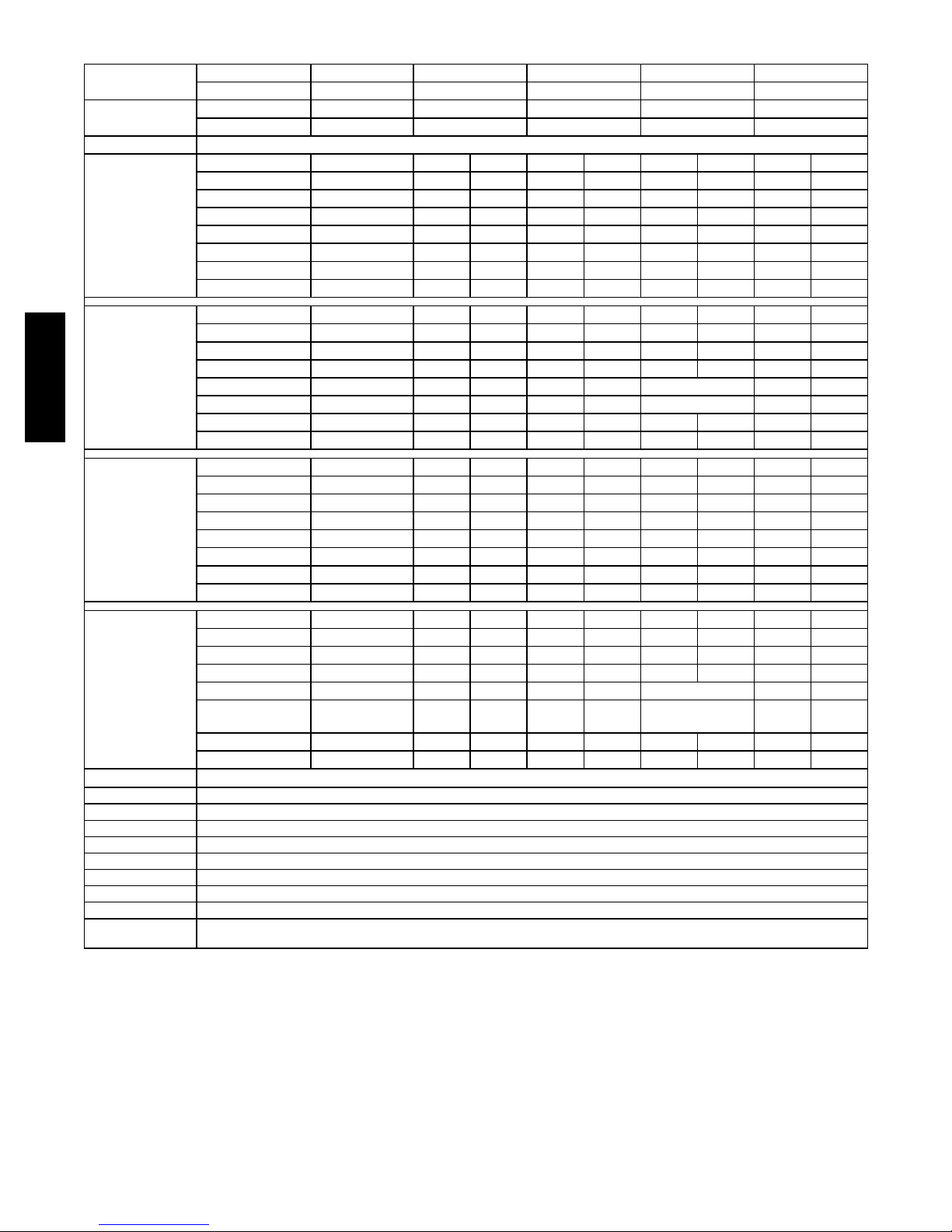
Table 5 – 569J*07-14A/B/G/H Piping Recommendations (Single-Circuit Unit)
Linear Length Ft 0 --- 2 5 25 --- 50 50 --- 75 75 --- 100 100 --- 125
m 0 --- 8 8 --- 1 5 15 - -- 23 23 --- 30 30 --- 38
Equivalent
Length
Model
569J*07A/B/G/ H
569J*08A/B
569J
569J*12A/B
569J*14A/B
Legend:
TC Total Capacity, MBH (at 45 F Saturated suction, 95 F outdoor air temp)
SC Sub ---cooling, degrees F (at liquid line valve)
Liquid PD (_F) Liquid line pressure drop, saturated temperature, degrees F
Max Lift Maximum liquid lift (Indoor unit ABOVE outdoor unit only), at maximum permitted pressure drop.
Max Lift PD (_F) Pr essure drop inclu ding Maximum liquid lift value
SuctionLnPD(_F) Suction line pressure drop, saturated temperature, degree F
(Cap Red) Capacity reduction caused by suction line pressure drop GT 2 deg F
#/TR Charge to unit capacity ratio, lbs per ton (at 45 F SST, 95 F ODA)
NOTE: For applications with equivalent length greater than 188 ft (57 m) and/or linear length greater than 125 ft (38 m), contact your local
Ft 0 --- 3 8 38 --- 75 75 --- 113 113 --- 150 150 --- 188
m 0 --- 1 2 12 --- 23 23 --- 34 34 --- 46 46 --- 57
Liquid Line size
3
/8”
3
/8”
1
/2”
1
/2”
5
/8”
1
/2”
5
/8”
Liquid PD (_F) 2.0 4.0 0.7 1.1 0.3 1.4 0.4 1.8 0.5
Max Lift 18 7 34 31 39 44 57 41 57
Max Lift PD (_F) 3.5 4.6 3.5 3.5 3.5 5.0 5.0 5.0 5.0
Suction Line size 7/8”
7
/8” 1 ---1/8”7/8” 1 ---1/8”7/8” 1 ---1/8”7/8” 1 ---1/8”
SuctionLnPD(_F) 0.9 1.8 0.5 2.7 0.8 3.6 1.0 4.5 1.3
Charge 10.8 11.8 13.7 15.2 18.5 16.9 21.3 18.7 24.2
#/TR 1.90 2.07 2.41 2.67 3.25 2.97 3.74 3.28 4.25
Liquid Line size
1
/2”
1
/2”
5
/8”
1
/2”
5
/8”
1
/2”
5
/8”
Liquid PD (_F) 0.6 1.3 0.3 1.9 0.5 2.5 0.7 3.2 0.9
Max Lift 25 50 50 75 75 100 100 97 97
Max Lift PD (_F) 2.7 5.4 4.5 8.1 6.7 10.8 9.0 11.2 8.9
Suction Line size 7/8”
7
/8” 1 ---1/8”7/8” 1 ---1/8” 1 ---1/8” 1 ---1/8” 1 ---3/8”
SuctionLnPD(_F) 1.5 3.1 0.8 4.6 1.2 1.6 2.1 0.7
Charge 13.6 15.4 16.1 17.2 20.5 19.5 23.3 21.5 27.1
#/TR 1.78 2.02 2.11 2.25 2.68 2.55 3.05 2.81 3.54
Liquid Line size
1
/2”
1
/2”
5
/8”
1
/2”
5
/8”
1
/2”
5
/8”
Liquid PD (_F) 0.9 1.9 0.5 2.8 0.8 3.8 1.0 4.7 1.3
Max Lift 25 40 50 28 54 34 68 22 65
Max Lift PD (_F) 2.9 5.0 4.5 5.0 5.0 6.5 6.4 6.5 6.4
Suction Line size 7/8”
7
/8” 1 ---1/8” 1 ---1/8” 1 ---3/8” 1 ---1/8” 1 ---3/8” 1 ---1/8” 1 ---3/8”
SuctionLnPD(_F) 2.4 4.8 1.2 1.8 0.6 2.4 0.9 3.1 1.1
Charge 15.7 17.5 19.7 19.8 23.1 21.6 26.1 23.6 29.2
#/TR 1.67 1.86 2.09 2.10 2.45 2.29 2.77 2.50 3.10
Liquid Line size 5/8”
5
/8” 3/4”
5
/8”
3
/4”
5
/8”
3
/4”
Liquid PD (_F) 0.4 0.8 0.4 1.2 0.6 1.6 0.8 2.0 1.1
Max Lift 23 16 23 10 18 28 38 21 36
Max Lift PD (_F) 1.8 1.84 1.84 1.8 1.8 3.3 3.3 3.3 3.3
Suction Line size 1 -- -1/8” 1 ---1/8” 1 ---3/8” 1 ---1/8” 1 ---3/8” 1 ---3/8” 1 ---3/8” 1 ---5/8”
SuctionLnPD(_F)
(Cap Red)
1.1 2.2 0.8 3.3
(---2.3%)
1.2 1.6 2.0 0.8
Charge 31.8 34.7 37.6 37.6 41.8 41.1 46.1 44.2 51.6
#/TR 2.62 2.86 3.09 3.09 3.44 3.38 3.79 3.64 4.24
Bryant representative.
1
/2”
1
/2”
1
/2”
5
/8”
5
/8”
5
/8”
5
/8”
3
/4”
12
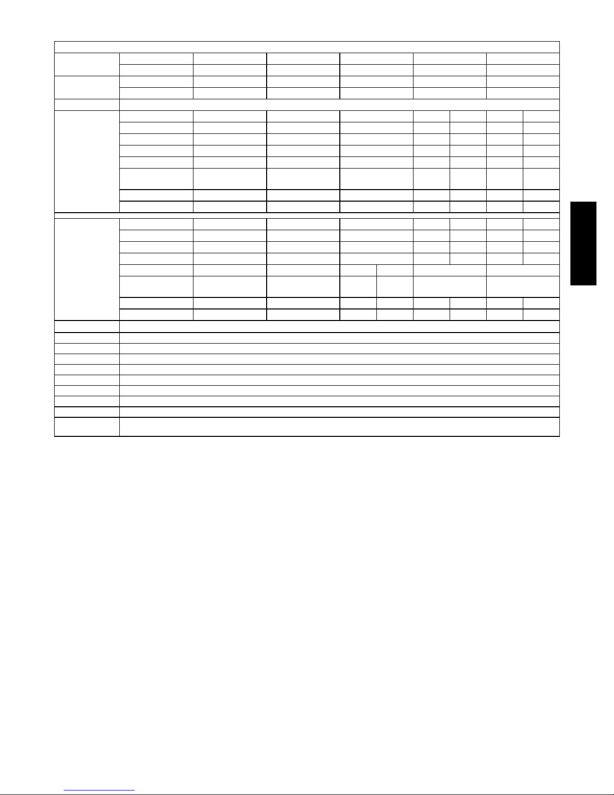
Table 6 – 569J*12-14D/E Piping Recommendations (Two-Circuit Unit)
NOTE: 569J*D/E requires TWO sets of refrigeration piping
Linear Length
Equivalent
Length
Model
569J*12D/E
569J*14D/E
Legend:
TC Total Capacity, MBH (at 45 F Saturated suction, 95 F outdoor air temp)
SC Sub -- -cooling, degrees F (at liqu id line valve)
Liquid PD (_F) Liquid line pressure drop, saturated temperature, degrees F
Max Lift Maximum liquid lift (Indoor unit ABOVE outdoor unit only), at maximum permitted pressure drop.
Max Lift PD (_F) Pressure drop including Maximum liquid lift value
SuctionLnPD(_F) Suction line pressure drop, saturated temperature, degree F
(Cap Red) Capacity reduction caused by suction line pressure drop GT 2 deg F
#/TR Charge to unit capacity ratio, lbs per ton (at 45 F SST, 95 F ODA)
NOTE: For applications with equivalent length greater than 188 ft (57 m) and/or linear length greater than 125 ft (38 m), contact your local Bryant
Ft 0 --- 2 5 25 --- 50 50 --- 75 75 --- 100 100 --- 125
m 0 --- 8 8 --- 1 5 15 --- 23 23 --- 30 30 --- 38
Ft 0 --- 3 8 38 --- 75 75 --- 113 113 --- 150 150 --- 188
m 0 --- 1 2 12 --- 23 23 --- 34 34 --- 46 46 --- 57
Liquid Line size
3
/8”
3
/8”
3
/8”
3
/8”
1
/2”
3
/8”
1
/2”
Liquid PD (_F) 1.4 2.7 5.5 5.5 0.9 6.9 1.1
Max Lift 25 50 75 82 100 66 125
Max Lift PD (_F) 3.4 6.8 10.2 12.1 9.0 12.1 11.2
Suction Line size3/4”
SuctionLnPD(_F)
(Cap Red)
1.4 1.2 1.8
7
/8”
7
/8”
7
/8” 1 ---1/8”7/8” 1 ---1/8”
2.5
(---0.8%)
0.8
3.1
(---1.9%)
0.9
Charge 9.0 10.0 11.0 12.1 15.7 13.1 17.7
#/TR 0.73 0.81 0.89 0.97 1.27 1.05 1.42
Liquid Line size
3
/8”
3
/8”
3
/8”
3
/8”
1
/2”
3
/8”
1
/2”
Liquid PD (_F) 2.1 4.1 6.2 8.2 1.5 10.3 1.8
Max Lift 128 50 75 69 155 42 125
Max Lift PD (_F) 4.0 8.1 12.1 13.6 9.4 13.6 11.7
Suction Line size7/8”
SuctionLnPD(_F)
1.0 1.9 2.9
(Cap Red)
7
/8”
7
/8” 1 ---1/8” 1 ---1/8” 1 ---1/8”
0.8 1.1 1.4
(---1.5%)
Charge 17.0 18.0 19.0 19.5 20.6 23.7 21.8 25.7
#/TR 1.36 1.44 1.52 1.56 1.65 1.90 1.74 2.05
representative.
569J
13
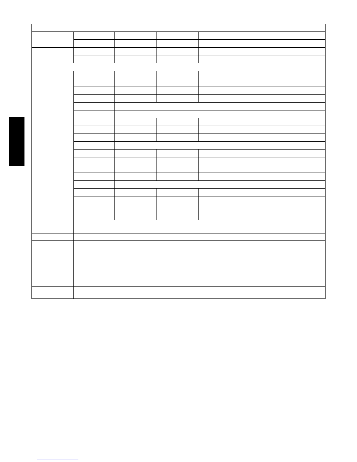
Table 7 – 569J*12F HGBP Piping Recommendations (Two-Circuit Unit)
NOTE: 569J*12F units require TWO sets of refrigeration piping
Linear Length Ft 0-25 25-50 50-75 75-100 100-125
m 0-8 8-15 15-23 23-30 30-38
Equivalent
Length
Model
569J*12F Liquid Line
569J
Ft 0-38 38-75 75-113 113-150 150-188
m 0-12 12-23 23-34 34-46 46-57
3
/
8
3
/
8
3
/
8
3
/
1
8
/
Pressure Drop 1.8 3.5 5.2 8.7 1.2 8.7 1.5
Max Lift 25 50 75 65 100 62 125
Pressure Drop 3.8 7.5 11.3 12.2 9.4 13.7 11.7
Suction Line
Circuit 1: VAPOR RISER REQUIRED, NOT GREATER THAN 20 FT (6.1 M) --- See Fig. 5)
Tube S
Tube A
5
/
8
5
/
8
1-1/
5
/
8
8
1-3/
5
/
8
8
1-3/
5
/
8
8
Pressure Drop 2.0 2.0 1.9 2.0 2.0
Circuit 1: VAPOR RISER GREATER THAN 20 FT (6.1 M) --- See Fig. 6)
Tube S
Tube A
5
5
Tube B NR
/
8
/
8
7
/
8
5
/
8
1
/
2
7
/
8
5
/
8
5
/
8
1-1/
5
/
5
/
8
8
8
Pressure Drop 2.0 1.6 1.7 1.7 2.1
Circuit 1: NO VAPOR RISER REQUIRED
Circui t 2:
7
/
8
7
/
8
7
/
8
7
/
8
1-1/
1-1/
8
8
1-1/
1-1/
8
8
Pressure Drop 1.1 2.1 0.9 1.2 1.5
Charge (lbs) 1/2 13.3 14.3 15.8 16.9 20.0 18.1 22.0
3
2
/
8
1-3/
5
/
8
1-1/
5
/
8
5
/
8
1-1/
1-1/
1
/
2
8
8
8
8
Legend:
Equivalent Length Equivalent tubing length, including effects of refrigeration specialties devices
Linear Length Typical linear tubing length (50% added to linear to define Equivalent Length for this table)
Liquid Line Tubing size, inches OD.
Max Lift Maximum liquid lift (indoor unit ABOVE outdoor unit only), at maximum permitted liquid line pressure drop —
Suction Line Tube size, inches OD
Charge Charge Quantity, lbs. Calculated for both liquid line sizes (where applicable), but only with larger suction line size (where applicable)
NOTE: For applications with equivalent length greater than 188 ft (57 m) and/or linear length greater than 125 ft (38 m), contact your local
S Linear Length Less than 75 ft (23 m): Minimum 2.0° F subcooling entering TXV
S Linear Length Greater than 75 ft (23m): Minimum 0.5° F subcooling entering TXV
Bryant representative.
14
Suction Riser —
A suction riser condition exists when the outdoor unit is
located above the indoor (evaporator) unit and suction
vapor must flow vertically up to return to the compressor.
Oil return is a concern when the suction tube size is too
large to produce the minimum refrigerant velocity to
ensure oil return at minimum load conditions.
569J***A/B/G/H and 569J***D/E (WITHOUT HGBP)
Check Table 8 for maximum suction tube size for 569J units
at minimum load conditions. Consider suction speed riser
(reduced tube size for vertical segment only) or double
suction riser arrangement if the planned suction tube size
does not provide necessary minimum flowrates for this riser.
Ta bl e 8 –
Model: Unit Size Maximum Tube Size
569J***A/B 07 13/
569J*07G/H 07 11/
569J***D/E 12 13/
569J*12F 12 See Table 7
569J Maximum Suction Pipe Size
8
08 15/
12 15/
14 21/
14 15/
8
8
8
8
8
8
A
20-FT (6.1 M) MAX
S
LEGEND
A - Suction Riser Without Trap
S - Suction Line to Condensing Unit
CONDENSING
UNIT
C12404
Fig. 5 -- Suction Line Piping -- Speed Riser
If the vertical elevation difference is greater than 20--ft
(6.1--m) linear feet or requires more than two short lift
segments, select the Circuit 1 suction line size from
Double Suction Riser lines data under VAPOR RISER
GREATER THAN 20 FT (6.1 M). See Fig. 6. Tube S is
the horizontal line size. Tube A is the reduced diameter
riser size without bottom trap; Tube B is the parallel riser
size with bottom oil trap.
A
S
569J
569J*12F UNIT WITH OPTIONAL HOT GAS BYPASS
Special consideration for suction riser requirements must
be considered when applying this factory--installed hot gas
bypass. It is extremely important to consider the lowest
possible refrigerant tons of refrigerant flow when hot gas
bypass is functioning to assure proper oil return up suction
risers.
Table 7 provides recommended tube sizes for model
569J*12F unit which includes the factory--installed hot
gas bypass system on Circuit 1. The selections in this
table are based on evaluations of system minimum load
operating conditions for comfort cooling applications,
with compressor saturated suction pressure to 28_F
(--2.2_C) minimum.
Table 7 includes liquid line size selections based on use of
RTPF coil option only.
Table 7 includes three different suction line size selections
for Circuit 1 based on the elevation difference conditions
between the 569J unit and the evaporator coil location.
Outdoor unit ABOVE evaporator coil: This installation
will have at least one suction riser segment. If the vertical
elevation difference is less than 20--ft (6.1 m) linear feet
and requires only one or two segments, consider a speed
riser selection for Circuit 1; use the line marked VAPOR
RISER REQUIRED; NOT GREATER THAN 20 FT
(6.1 M). See Fig. 5. Tube S is the horizontal line size;
tube A is the reduced diameter riser size.
S
FROM
EVAPORATOR
LEGEND
A - Suction Riser Without Trap
B - Suction Riser With Trap
S - Suction Line to Condensing Unit
B
C12405
Fig. 6 -- Suction Line Piping -- Double Riser
Outdoor unit BELOW evaporator coil and no vertical
riser segments: Select Circuit 1 suction line size from
NO VAPOR RISER line.
Circuit 2 suction line: Because there is no hot gas bypass
system in Circuit 2, no special riser selections are
necessary. Select Circuit 2 suction line from bottom line
for all 569J*12F installations.
Vertical Separation (outdoor unit above indoor unit) –
Vertical elevation difference of 200 ft (60 m) is permitted
when the outdoor unit (569J***A/B/G/H or
569J***D/E/F) is located above the indoor unit.
15
Step 6 — Complete Refrigerant Piping Connections
IMPORTANT: Do not bury refrigerant piping
underground.
IMPORTANT: A refrigerant receiver is not provided
with the unit. Do not install a receiver.
Provide Safety Relief —
If local codes dictate an additional safety relief device,
purchase locally and install locally. Installation will
require the recovery of the factory shipping charge before
the factory tubing can be cut and the supplemental relief
device is installed.
Model 568J***D/E/F has two separate refrigeration systems.
If required, each circuit will require a field-supplied/installed
supplemental relief device.
Check 569J Model with Evaporator Coil Connections —
569J
Confirm before installation of unit that the evaporator coil
connections are consistent with this 569J model. See
Table 3 on page 10.
Insulate Suction Lines —
Apply closed-cell tubular insulation to all suction lines
between evaporator coil connection and 569J unit’s suction
service valve.
569J***D/E/F Piping Connections —
The 569J***D/E/F’s two circuits are designated Circuit 1
and Circuit 2. Circuit 1 is controlled by the thermostat’s Y1
(or TC1) contact and will be the first circuit on and last
circuit off. Circuit 2 is controlled by the thermostat’s Y2 (or
TC2) contact and this circuit is always the “lag” circuit.
Plan the Circuit 1 and Circuit 2 tubing segments carefully,
mark each segment and check constantly as piping
systems are assembled to avoid piping errors.
569J***D/E/F unit cannot be field-piped as a
single-circuit/tandem system.
Final Tubing Check. 569J***D/E/F —
Before completing the field piping connections to the
569J***D/E/F unit service valves, confirm that the
suction line to the indoor coil’s first--on/last--off circuit
(and its companion liquid line) are correctly identified as
Circuit 1 use for the 569J***D/E/F unit. If a suction riser
is required, it must be in Circuit 1.
Connecting 524J to 569J***D/E/F: The 524J fan coil in
sizes 12, 14 and 16 is a face-split coil design that also has its
circuits designated as 1 and 2. See Fig. 8. Note that the
lower coil segment changes as the arrangement of the 524J
changes. In a vertical arrangement, the 524J’s lower coil
segment is segment 2; this segment should be connected to
the 569J***D/E/F’s Circuit 1. In a horizontal arrangement,
the 524J’s lower segment is now segment 1; this segment
should be connected to the 569J***D/E/F’s Circuit 1.
Note that refrigerant suction piping should be insulated.
524J
Arrangement
Vertical
Horizontal
Cooling
Stage
Y1
Y2
Y1
Y2
524J Coil
Segment
2
1
1
2
Connect to
569J***D/E/F
Circuit 1
Circuit 2
Circuit 1
Circuit 2
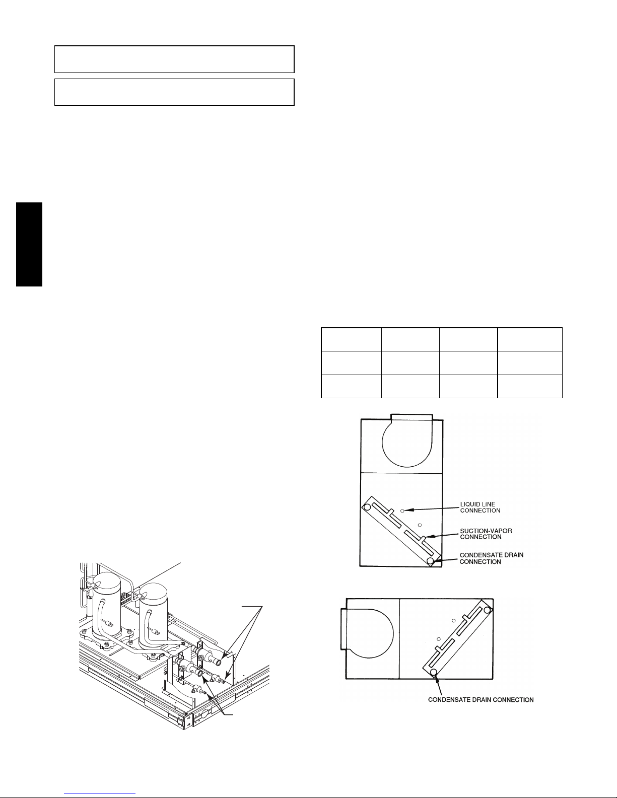
See Fig. 7 for location of Circuit 1 and Circuit 2 service
valves and field piping connections. Circuit 1 is on the
right-hand side of the service valve compartment; Circuit 2
is on the left.
When a single piece evaporator coil with two separate circuits
is connected to a 569J***D/E/F, the lower coil circuit should
be connected to the 569J***D/E/F’s Circuit 1 so that the
evaporator’s lower coil segment is first-on/last-off (to avoid
re-evaporation of condensate on dry lower coil segments).
CKT
2
CKT
1
Circuit 1
Connections
Connections
Circuit 2
C10912
Fig. 7 -- 569J***D/E/F Service Valve Locations
1
2
FIRS T ON/LA ST OFF = 2
VERTICAL INSTALLATION
2
1
FIRS T ON /LAST OF F = 1
HORIZONTAL INSTALLATIO N
C10071
Fig. 8 -- Typical Evaporator Coil Connections (524J)
16
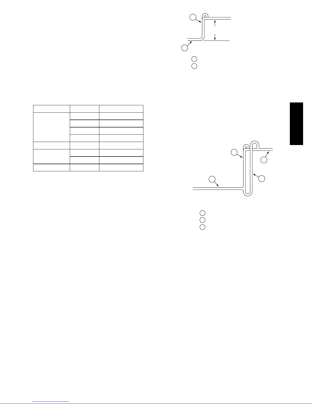
Install Filter Drier(s) and Moisture Indicator(s) —
Every unit MUST have a filter drier in the liquid line.
569J***D/E/F models require two filter driers (one in each
liquid line). Locate the filter drier(s) at the indoor unit, close to
the evaporator coil’s thermal expansion valve (TXV) inlets.
569J units include one (569J***A/B/G/H) or two
(569J***D/E/F) Puron-duty filter drier(s), shipped in cartons
attached to the unit basepan. Remove the filter drier(s) and
prepare to install in the liquid line(s) at the evaporator coil.
Do not remove connection fitting plugs until ready to
connect and braze the filter drier into the liquid line position.
Table 9 – Puron-duty Filter Drier(s)
Model-Size Qty
569J*07
A/B/G/H
569J*08A/B 1
569J*12A/B 1
569J*14A/B 1
569J*12D/E/F 2
569J*14D/E 2
Liquid
Line OD
3
1
/8-in 8cu.in. KH43LG091
1
/2-in 16 cu. in. KH43LG085
1
/2-in 16 cu. in. KH43LG085
5
/8-in 16 cu. in. KH43LG086
3
/8-in 8cu.in. KH43LG091
1
/2-in 16 cu. in. KH43LG085
Desiccant
Volume
Part
Number Ref
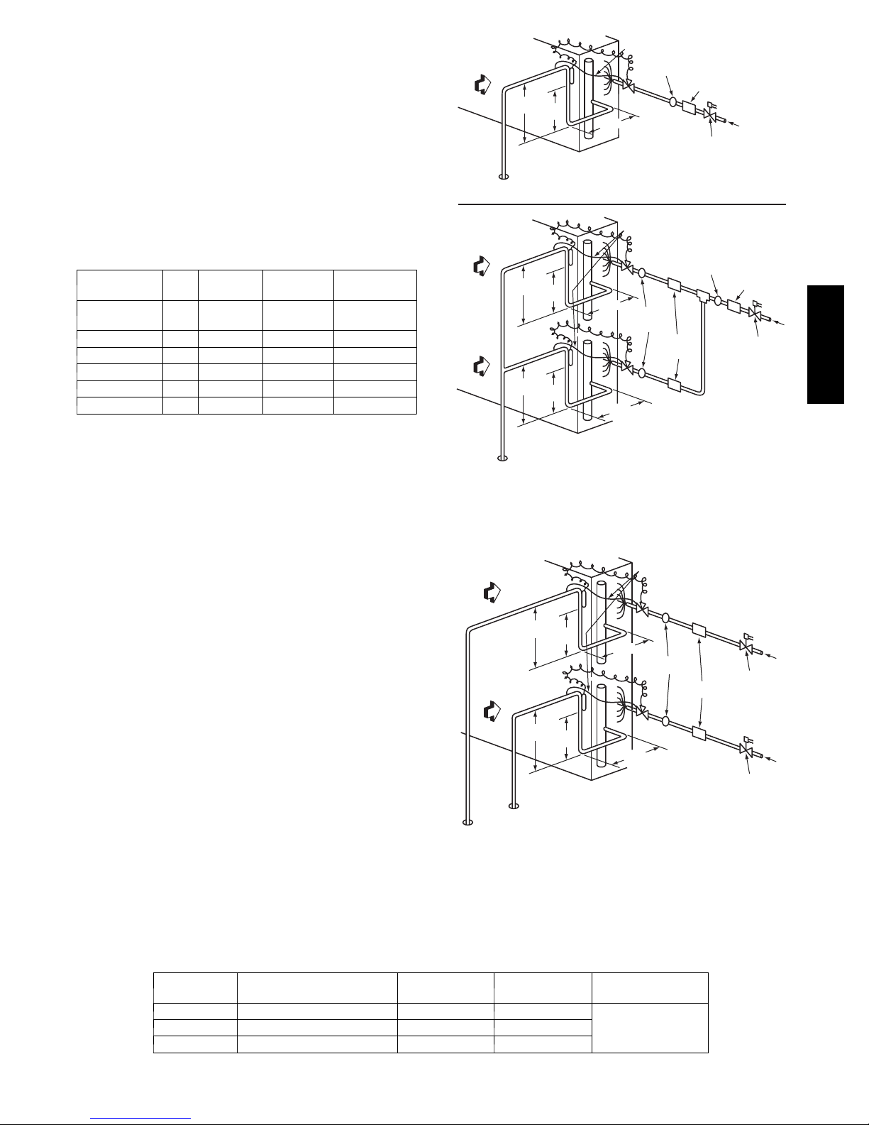
Installation of liquid line moisture indicating sightglass in
each circuit is recommended. Locate the sightglass(es)
between the outlet of the filter drier and the TXV inlet.
Refer to Table 10 for recommendations on refrigeration
specialties.
In some applications, depending on space and convenience
requirements, it may be desirable to install 2 filter driers and
sight glasses in a single circuit application. One filter drier
and sight glass may be installed at A locations (see Fig. 9)
or 2 filter driers and sight glasses may be installed at B
locations (see Figs. 9 and 10).
Select the filter drier for maximum unit capacity and
minimum pressure drop. Complete the refrigerant piping
from the indoor unit to the outdoor unit before opening
the liquid and suction lines at the outdoor unit.
Install Liquid Line Solenoid Valve —
It is recommended that a solenoid valve be placed in the
main liquid line (see Figs. 9 and 10) between the condensing
unit and the evaporator coil. Locate the solenoid valve at the
outlet end of the liquid line, near the evaporator coil
connections, with flow direction arrow pointed at the
evaporator coil. Refer to Table 10. (A liquid line solenoid
valve is required when the liquid line length exceeds 75 ft
[23 m].) This valve prevents refrigerant migration (which
causes oil dilution) to the compressor during the off cycle, at
low outdoor ambient temperatures. Wire the solenoid in
parallel with the compressor contactor coil (see Figs. 9 and
10). This means of electrical control is referred to as
solenoid drop control.
Table 10 – Refrigerant Specialties Part Numbers
LIQUID LINE
SIZE (in.)
3
/
8
1
/
2
5
/
8
569J***D/E/F units require TWO sets of parts.
LIQUID LINE
SOLENOID VALVE (LLSV)
EF680033 EF680037 KM680008
EF680035 EF680037 KM680004
EF680028 EF680032 KM680005
8 DIAMS
MIN
8 DIAMS
MIN
8 DIAMS
EQUALIZER LINE
TXV
EQUALIZER LINE
TXV
CKT 2
SIGHT
GLASSES
B LOCATION
TXV
CKT 1
MIN
SIGHT GLASS
A LOCATION
FILTER
DRIERS
B LOCATION
FILTER DRIER
A LOCATION
LIQUID LINE
SOLENOID
VALVE
SIGHT GLASS
A LOCATION
INDOOR
COIL CKT
AIRFLOW
INDOOR
COIL CKT 2
AIRFLOW
INDOOR
COIL CKT 1
AIRFLOW
TXV
SENSING
BULB
15 DIAMS
10
MIN
DIAMS
Single Circuit Coil Piping Configuration
For single compressor condensing units
TXV
SENSING
BULB
15 DIAMS
10
MIN
DIAMS
TXV
SENSING
BULB
15 DIAMS
10
MIN
DIAMS
Dual Circuit Coil Piping Configuration
For single compressor condensing units
Fig. 9 -- Location of Sight Glass(es) and Filter Driers
Typical 569J***A/B/G/H Systems
8 DIAMS
MIN
8 DIAMS
EQUALIZER LINE
TXV
CKT 2
TXV
CKT 1
MIN
SIGHT
GLASSES
FILTER
DRIERS
AIRFLOW
AIRFLOW
SUCTION
CIRCUIT 2
TXV
SENSING
BULB
15 DIAMS
10
MIN
DIAMS
TXV
SENSING
BULB
15 DIAMS
10
MIN
DIAMS
SUCTION
CIRCUIT 1
Dual Circuit Coil Piping Configuration
For two circuit condensing units
Fig. 10 -- Location of Sight Glasses and Filter Driers
Typical 569J***D/E/F Systems
LLSV
COIL
17
SIGHT
GLASS
FILTER
DRIER
provided with unit
see Table 9
FLOW
FILTER DRIER
A LOCATION
LIQUID LINE
SOLENOID
VALVE
LIQUID LINE
SOLENOID VALVE
CIRCUIT 2
LIQUID LINE
SOLENOID VALVE
CIRCUIT 1
FLOW
569J
C10202
FLOW
FLOW
C10072
 Loading...