

Page 1
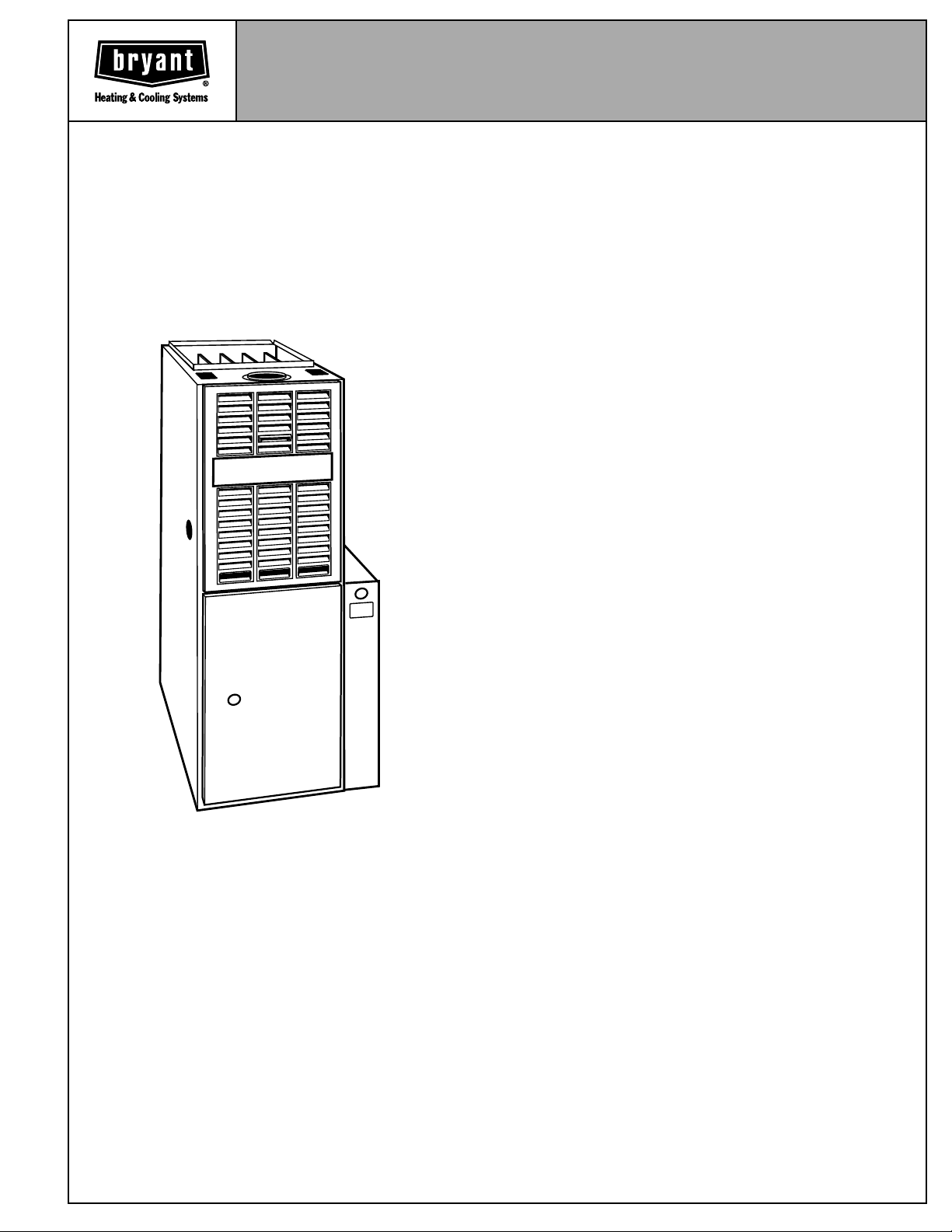
ENERGY-EFFICIENT
INDUCED-COMBUSTION
DELUXE UPFLOW FURNACE
With a unique approach to induced-combustion design, a 40-in.
tall cabinet, 4-pass heat exchanger, an inshot burner system,
and its safety features, this furnace is without peer. The model
395CAV Deluxe Induced-Combustion Upflow Furnace achieves
one of the highest Annual Fuel Utilization Efficiency (AFUE) ratings available in a noncondensing, induced-combustion furnace.
Its ease and economy of installation, ease of serviceability, economical initial cost, and short payback time put it in a class well
ahead of the competition. The model 395CAV Gas Furnace has
the kind of overall performance needed in today’s homes. All
models are GAMA efficiency rating certified and certified for use
in California Air Quality Management Districts.
Sizes 045 thru 155
395CAV
Series H and J
FEATURES
EFFICIENCY —The 395CAV Deluxe Induced-Combustion Gas
Furnace provides the efficiency customers want with 80.0 percent AFUE.
MEDIA FILTER CABINET —Enhanced indoor air quality in your
home is made easier with our media filter cabinet—a standard
accessory on all deluxe upflow furnaces. When installed as a
part of your system, this cabinet allows for easy and convenient
addition of a Bryant high-efficiency air filter.
HOT SURFACE IGNITION —This field proven ignition system
will save energy and improve reliability.
ALUMINIZED HEAT EXCHANGER —The patented 4-pass heat
exchanger is made of aluminized steel and backed by a 20-year
Limited Warranty.
INTELLIGENT CONTROL BOARD —The 395CAV Furnace has
an intelligent control board with an LED status indicator light to
ensure top furnace performance. This control board also has a
self-test feature that enables the servicing technician to verify
operation of the board itself, the inducer, the hot surface ignitor,
both high- and low-speed blower operation, and the humidifier.
The board also features a 3-amp fuse that protects the transformer and board. We guarantee the reliability of the control
board with a 3-year Limited Warranty.
40-IN. HEIGHT —The 395CAV Deluxe Induced-Combustion
Furnace with a 40-in. cabinet height simplifies installation in alcoves, attics, basements (ideal for short basement), closets, and
utility rooms, especially with a high-efficiency cooling coil.
PREPAINTED CABINET —The 395CAV uses prepainted sheet
metal for the cabinet. This is the same high-quality finish found
on refrigerators and other appliances today. We ensure its durability by using a galvanized steel substrate to provide superior
rust protection.
PATENTED BLOCKED VENT SAFEGUARD —Our induced-
combustion furnace has a patented blocked vent safeguard. The
safeguard will stop furnace operation if the vent system becomes blocked or is not operating properly. An exclusive with the
395CAV Furnace.
EASY INSTALLATION —The model 395CAV has many fea-
tures that make installation easier: left or right gas and electrical
connections, Molex blower speed selector, matching coil sizes,
accessory low-voltage connections, and many more.
QUIET OPERATION —A soft mount inducer assembly and slow
opening gas valve improves sound level.
Form No. PDS 395CAV.40.8
Page 2
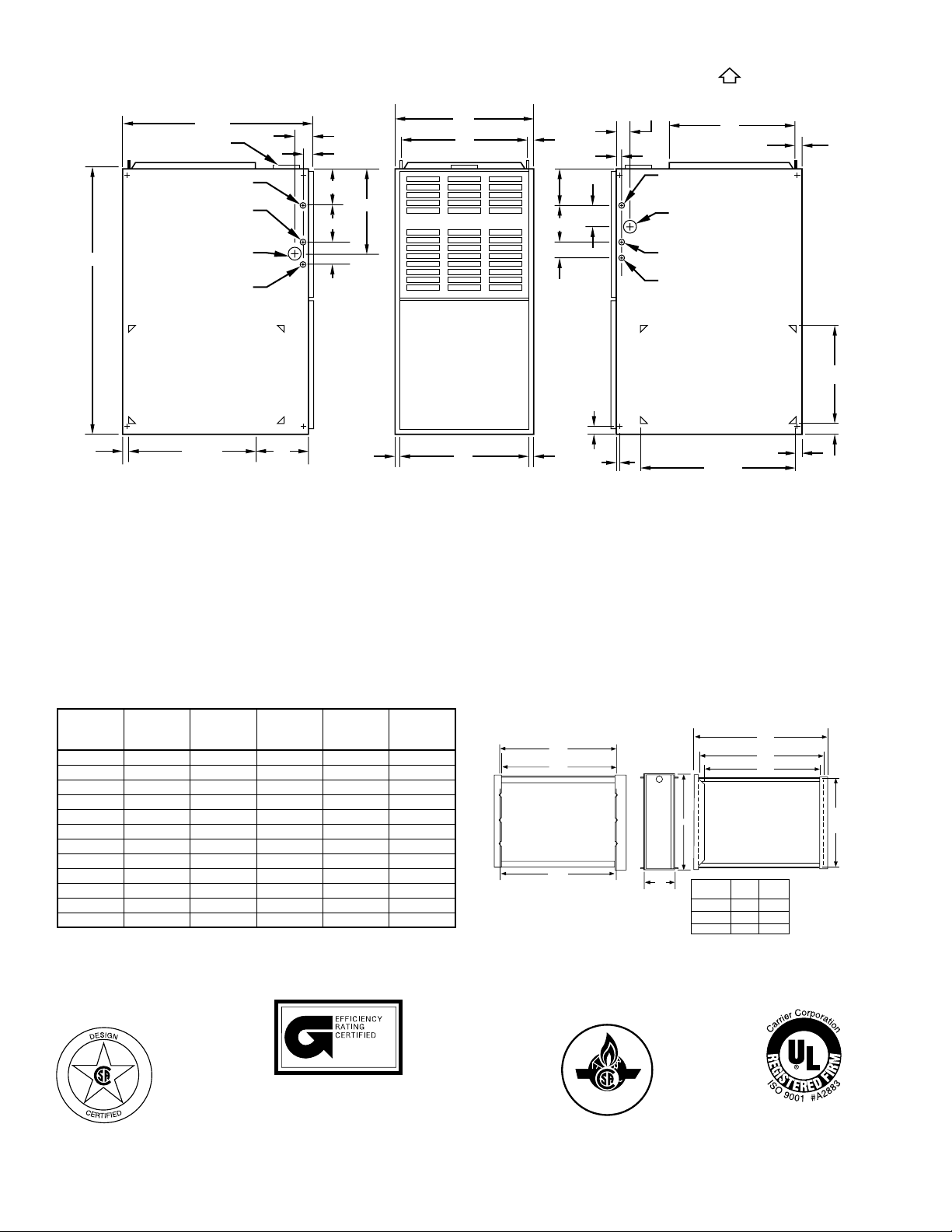
39 7⁄8″
VENT CONN
7
⁄8-IN. DIA HOLE
POWER ENTRY
ACCESSORY
3
1
⁄4-IN. DIA HOLE
1
⁄2-IN. DIA HOLE
THERMOSTAT
WIRE ENTRY
28 1⁄2″
7
⁄8-IN. DIA
GAS ENTRY
2 1⁄16″
1″
5 3⁄8″
5 13⁄16″
2 3⁄8″
12 5⁄16″
AIRFLOW
A
D
13
⁄16″
5 3⁄8″
5 13⁄16″
2 3⁄8″
2 11⁄16″
2 1⁄16″
1″
7
⁄8-IN. DIA
POWER ENTRY
1
R.H. GAS ENTRY
7
⁄8-IN. DIA ACCESSORY
1
⁄2-IN. DIA THERMOSTAT
WIRE ENTRY
OUTLET
1
⁄2-IN. DIA
19″
13
⁄16″
SIDE INLET
11
⁄16″
NOTES:
24 5⁄16″
AIR INLET
1. Two additional 7⁄8-in. dia holes are located in the top plate.
2. Minimum return-air openings at furnace, based on metal duct. If flex duct is used,
see flex duct manufacturer's recommendations for equivalent diameters.
3. Minimum return-air opening at furnace:
a. For 800 CFM–16-in. round or 14
b. For 1200 CFM–20-in. round or 14
c. For 1600 CFM–22-in. round or 14
d. For airflow requirements above 1800 CFM, see Air Delivery table in Product Data literature for specific
use of single side inlets. The use of both side inlets, a combination of 1 side and the bottom, or the
bottom only will ensure adequate return air openings for airflow requirements above 1800 CFM.
3″
11
⁄16″
1
⁄2 x 12-in. rectangle.
1
⁄2 x 191⁄2-in. rectangle.
1
⁄2 x 231⁄4-in. rectangle.
DIMENSIONS (In.) MEDIA FILTER CABINET
UNIT
SIZE A D E
VENT
CONN*
(Dia)
024045 14-3/16 12-9/16 11-11/16 4 122
036045 14-3/16 12-9/16 11-11/16 4 124
024070 14-3/16 12-9/16 11-11/16 4 132
036070 14-3/16 12-9/16 11-11/16 4 134
042091 17-1/2 15-7/8 16 4 150
048091 21 19-3/8 18-1/2 4 154
036111 17-1/2 15-7/8 16 4 160
048111 21 19-3/8 18-1/2 4 166
060111 24-1/2 22-7/8 22 4 184
048135 21 19-3/8 18-1/2 5† 178
060135 24-1/2 22-7/8 22 5† 194
060155 24-1/2 22-7/8 22 5† 204
* Refer to the furnace Installation Instructions for proper venting procedures.
† Oval collar
SHIPPING
WEIGHT
(Lb)
SIDE INLET
14
1
⁄2″
TYP 1″
1
1
⁄4″
11
E
⁄16″
23
5/8
"
3/8
"
23
Furnace Side
3/4
"
23
Centerline Screw Slots
5
TYP
⁄8″
5
3/4
23
SIDE RETURN
DUCT LOCATION
A
"
Media/
Filter Cabinet
16" 17 16"
20" 21 20"
24" 25 24"
1
⁄4″
25
24
Opening with Flanges Bent
23
Opening
Duct Side
AB
1″
A98520
5/8
"
3/8
"
1/8
"
B Opening
A00309
ama
MEETS DOE RESIDENTIAL CONSERVATION
SERVICES PROGRAM STANDARDS.
Before purchasing this appliance, read important
energy cost and efficiency information available
from your retailer.
—2—
CERTIFIED
REGISTERED
QUALITY SYSTEM
Page 3
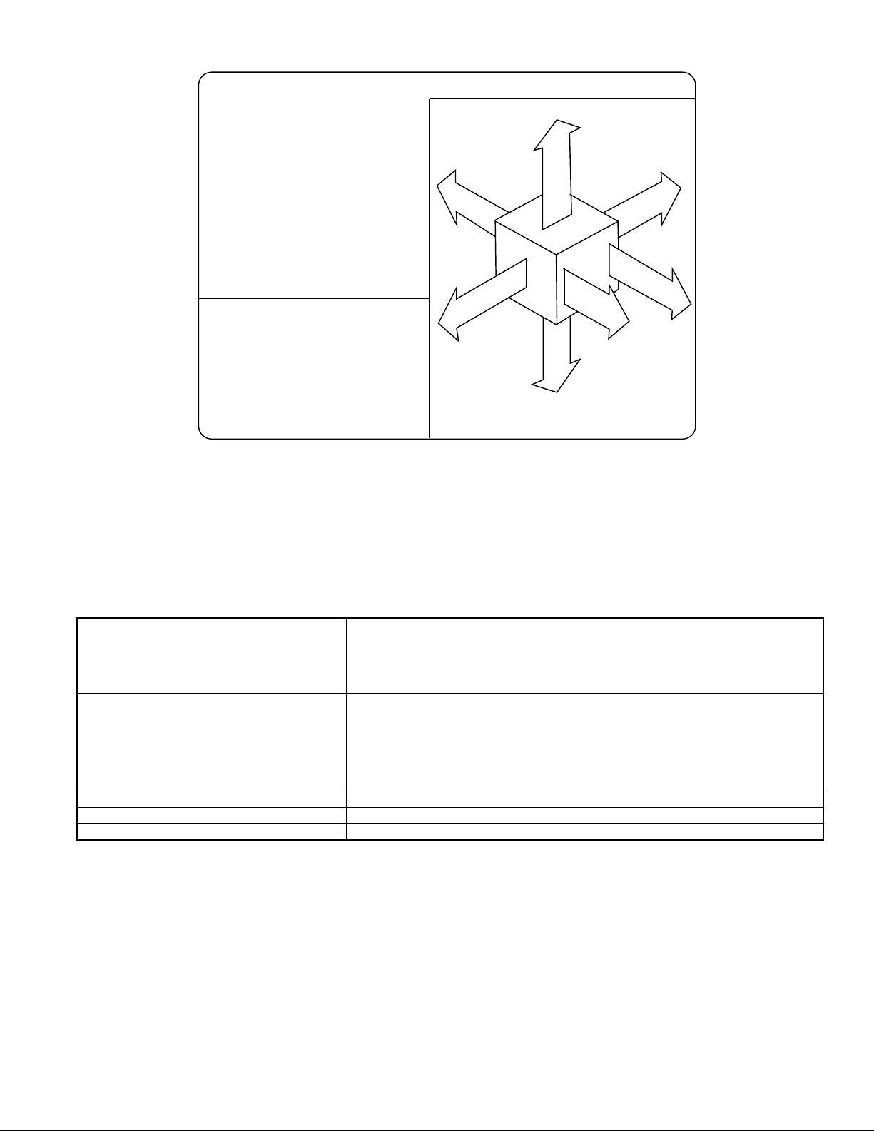
MINIMUM INCHES CLEARANCE TO COMBUSTIBLE CONSTRUCTION
his forced air fur nnace is equipped for use with
atural gas at altitudes 0 - 10,000 ft (0-3,050m).
n accessory kit, supplied by the mman ufactu rer,
all be used to convert to propane gas use or
y be required for some na tural gas applications.
hiss furnace is for indoor installation in
uilding constructed on site.
his f
urnace may be installled on combustible
oorring in alcove or closet at minimum clearance
f
m combustible material.
f
his furnace ma
a
nd may be vented in common with other gas-fired
a
pliances.
For furnaces wider than 14.25 inches
#
(362mm) may be 0 inches.
For s in g le w all ven t ty p e 6 inc he s .
#
For Type B-1 vent type 3 inches.
y be used with a Type B-1 Vent
This furnace is approved for UPFLO W installations only.
1"
0"
B
A
C
K
E
D
I
S
TOP / PLENUM
N
R
U
F
F
1" #
BOTTOM
Clearance in inches.
Vent Clearance to comb ustibles:
For Single Wall vents 6 inches (6 po).
For Type B-1 vent type 1 inch (1 po ).
DESSOUS
"
0
E
C
A
T
N
O
R
F
R
O
N
T
##
S
320325-101 RE V. H
1"
E
D
I
S
E
R
V
I
C
E
#
30"
MIN
CONTROLS—THERMOSTATS AND ZONING
Auto Changeover, °F/°C, 1-Stage Heat/1-Stage Cool — TSTATBBNAC01-B
Auto Changeover, °F/°C, 2-Stage Heat/1-Stage Cool — TSTATBBNHP01-B
THERMOSTAT—NON-PROGRAMMABLE
THERMOSTAT—PROGRAMMABLE
ZONING—2-ZONE ZONEBB2KIT01, ZONEKIT2ZBDP
ZONING—4-ZONE ZONEBB4KIT01
ZONING—8-ZONE ZONEBB8KIT01
* Do not use in zoning heat pump applications.
Auto Changeover, °F/°C, 2-Stage Heat/2-Stage Cool — TSTATBBN2S01-B
in AC Mode, 3-Stage Heat in AC Mode/2-Stage Cool in HP Mode
Air Conditioner, 1-Stage Heat/1-Stage Cool, Manual Changeover, °F/°C — TSTATBBBAC01
Heat Pump, 2-Stage Heat/1-Stage Cool, Manual Changeover, °F/°C — TSTATBBBHP01*
Auto Changeover, 7-Day Programmable, °F/°C, 1-Stage Heat/1-Stage Cool — TSTATBBPAC01-B
Auto Changeover, 7-Day Programmable, °F/°C, 2-Stage Heat/1-Stage Cool — TSTATBBPHP01-B
Auto Changeover, 7-Day Programmable, °F/°C, 2-Stage Heat/2-Stage Cool — TSTATBBP2S01-B
in AC Mode, 3-Stage Heat/2-Stage Cool in HP Mode
Dual Fuel Thermostat, Includes Outdoor Air Temperature Sensor — TSTATBBPDF01-B*
Thermidistat Control — Non-Programmable/Programmable Thermostat — TSTATBBPRH01-B*
with Humidity Control (For use in Dual Fuel, AC, HP, and 2S applications. Includes Outdoor Air
Temperature Sensor.)
A98122E
—3—
Page 4

SPECIFICATIONS
UNIT SIZE 024045 036045 024070 036070 042091 048091
RATINGS AND PERFORMANCE
Input Btuh* 44,000 44,000 66,000 66,000 88,000 88,000
Output Capacity (Btuh)† Nonweatherized ICS 35,000 35,000 53,000 53,000 71,000 71,000
AFUE† Nonweatherized ICS 80.0 80.0 80.0 80.0 80.0 80.0
Certified Temperature Rise Range °F25—55 15—45 40—70 30—60 40—70 30—60
Certified External Static Pressure Heat/Cool 0.10/0.50 0.10/0.50 0.12/0.50 0.12/0.50 0.15/0.50 0.15/0.50
Airflow CFM‡ Heating 855 980 830 1140 1170 1445
ELECTRICAL
Unit Volts—Hertz—Phase 115—60—1
Operating Voltage Range Min—Max 104—127
Maximum Unit Amps 6.0 8.3 5.9 8.7 9.0 10.4
Maximum Wire Length (Measured 1 Way in Ft) 47 34 47 32 31 27
Minimum Wire Size 14
Maximum Fuse or Ckt Bkr Size (Amps)** 15
Transformer (24v) 40va
External Control Heating 12va
Power Available Cooling 35va
Air Conditioning Blower Relay Standard
CONTROLS
Limit Control SPST
Heating Blower Control Solid-State Time Operation
Burners (Monoport) 2 2 3 3 4 4
Gas Connection Size 1/2-in. NPT
GAS CONTROLS
Gas Valve (Redundant) White Rodgers
Min Inlet Pressure (In. wc) 4.5 (Natural Gas)
Max Inlet Pressure (In. wc) 13.6 (Natural Gas)
Ignition Device Hot Surface
BLOWER DATA
Direct-Drive Motor HP (PSC) 1/5 1/3 1/5 1/3 1/3 1/2
Motor Full Load Amps 2.9 5.8 2.9 5.8 5.8 7.9
RPM (Nominal)—Speeds 1075—3 1075—4 1075—3 1075—4 1075—4 1075—4
Blower Wheel Diameter x Width (In.) 10 x 6 10 x 6 10 x 6 10 x 6 10 x 7 10 x 8
Filter Size (In.)—Permanent Washable (Supplied) (1) 16 x 25 x 1 (1) 20 x 25 x
FACTORY-AUTHORIZED DEALER-INSTALLED ACCESSORIES
Twinning Kit N/A
Gas Conversion Kit—Natural-to-Propane KGANP2001ALL
Gas Conversion Kit—Propane-to-Natural KGAPN1601ALL
Air Cleaner Model AIRA or 902B
Humidifier Model HUM
Ventilator Model VA3B, VB5B, VC5B, or VL3A
* Gas input ratings are certified for elevations to 2000 ft. For elevations above 2000 ft, reduce ratings 4 percent for each 1000 ft above sea level. Refer to
National Fuel Gas Code Table F4 or furnace Installation Instructions. In Canada, derate the unit 10 percent for elevations 2000 ft to 4500 ft above sea level.
† Capacity and AFUE in accordance with U.S. government DOE test procedures.
‡•Airflow shown is for bottom only return-air supply with factory-supplied 1-in. washable filter(s).
• For air delivery above 1800 CFM, see Air Delivery table for other options.
• An airflow reduction of up to 7% may occur when using the factory-specified 4-5/16-inch wide, high efficiency media filter.
• For best furnace efficiency when using the 4-5/16-inch wide media filter, adjust the blower speed tap to near the mid-point of the rise range.
** Time-delay type is recommended.
ICS—Isolated Combustion System
N/A—Not Applicable
Cooling 880 1250 880 1195 1360 1740
1
KGATW0401HSI
—4—
Page 5

SPECIFICATIONS
UNIT SIZE 036111 048111 060111 048135 060135 060155
RATINGS AND PERFORMANCE
Input Btuh* 110,000 110,000 110,000 132,000 132,000 154,000
Capacity (Btuh)† Nonweatherized ICS 89,000 89,000 89,000 107,000 107,000 124,000
AFUE† Nonweatherized ICS 80.0 80.0 80.0 80.0 80.0 80.0
Certified Temperature Rise Range °F55—85 45—75 25—55 50—80 40—70 50—80
Certified External Static Pressure Heat/Cool 0.20/0.50 0.20/0.50 0.20/0.50 0.20/0.50 0.20/0.50 0.20/0.50
Airflow CFM‡ Heating 1175 1415 1750 1645 1775 1770
ELECTRICAL
Unit Volts—Hertz—Phase 115—60—1
Operating Voltage Range Min—Max 104—127
Maximum Unit Amps 8.0 10.1 14.4 10.1 13.3 14.0
Maximum Wire Length (Measured 1 Way in Ft) 35 28 31 28 33 31
Minimum Wire Size 14 14 12 14 12 12
Maximum Fuse or Ckt Bkr Size (Amps)** 15 15 20 15 20 20
Transformer (24v) 40va
External Control Heating 12va
Power Available Cooling 35va
Air Conditioning Blower Relay Standard
CONTROLS
Limit Control SPST
Heating Blower Control Solid-State Time Operation
Burners (Monoport) 5 5 5 6 6 7
Gas Connection Size 1/2-in. NPT
GAS CONTROLS
Gas Valve (Redundant) White Rodgers
Min Inlet Pressure (In. wc) 4.5 (Natural Gas)
Max Inlet Pressure (In. wc) 13.6 (Natural Gas)
Ignition Device Hot Surface
BLOWER DATA
Direct-Drive Motor HP (PSC) 1/3 1/2 3/4 1/2 3/4 3/4
Motor Full Load Amps 5.8 7.9 11.1 7.9 11.1 11.1
RPM (Nominal)—Speeds 1075—4 1075—4 1075—4 1075—4 1075—4 1075—4
Blower Wheel Diameter x Width (In.) 10 x 7 10 x 8 11 x 10 10 x 8 11 x 10 11 x 10
Filter Size (In.)—Permanent Washable (1) 16 x 25 x 1 (1) 20 x 25 x 1 (1) 24 x 25 x 1 (1) 20 x 25 x 1 (1) 24 x 25 x 1
FACTORY-AUTHORIZED DEALER-INSTALLED ACCESSORIES
Twinning Kit N/A KGATW0401HSI
Gas Conversion Kit—(Natural-to-Propane) KGANP2001ALL
Gas Conversion Kit—(Propane-to-Natural) KGAPN1601ALL
Air Cleaner Model AIRA or 902B
Humidifier Model HUM
Ventilator Model VA3B, VB5B, VC5B, or VL3A
* Gas input ratings are certified for elevations to 2000 ft. For elevations above 2000 ft, reduce ratings 4 percent for each 1000 ft above sea level. Refer to
National Fuel Gas Code Table F4 or furnace Installation Instructions. In Canada, derate the unit 10 percent for elevations 2000 ft to 4500 ft above sea level.
† Capacity and AFUE in accordance with U.S. government DOE test procedures.
‡•Airflow shown is for bottom only return-air supply with factory-supplied 1-in. washable filter(s).
• For air delivery above 1800 CFM, see Air Delivery table for other options.
• An airflow reduction of up to 7% may occur when using the factory-specified 4-5/16-inch wide, high efficiency media filter.
• For best furnace efficiency when using the 4-5/16-inch wide media filter, adjust the blower speed tap to near the mid-point of the rise range.
** Time-delay type is recommended.
ICS—Isolated Combustion System
N/A—Not Applicable
Cooling 1205 1575 2225 1620 2025 2055
—5—
Page 6

AIR DELIVERY—CFM (With Filters)*
UNIT
SIZE
024045
036045
024070
036070
042091
048091
036111
048111
060111
048135
060135
060155
* A filter is required for each return-air supply. Airflow shown is with factory supplied 1-in. washable filter(s). An airflow reduction of up to 7% may occur when
using the factory specified 4-5/16-inch wide, high-efficiency media filter. For best furnace efficiency when using the 4-5/16-inch wide media filter, adjust the
blower speed tap to near the mid-point of the rise range.
— Indicates unstable operating conditions.
RETURN-AIR
SUPPLY SPEED
Bottom
or
1 Side
Bottom
or
1 Side
Bottom
or
1 Side
Bottom
or
1 Side
Bottom
or
1 Side
Bottom
or
1 Side
Bottom
or
1 Side
Bottom
or
1 Side
Bottom
Only
Both Sides or
1 Side & Bottom
1 Side Only
Bottom
or
1 Side
Bottom
Only
Both Sides or
1 Side & Bottom
1 Side Only
Bottom
Only
Both Sides or
1 Side & Bottom
1 Side Only
0.1 0.2 0.3 0.4 0.5 0.6 0.7 0.8
High 1030 1005 970 925 880 815 745 615
Med-High 855 830 800 765 720 670 595 485
Med-Low 755 725 695 650 605 555 475 400
High 1490 1430 1385 1325 1250 1175 1085 975
Med-High 1335 1305 1270 1230 1160 1090 1005 915
Med-Low 1140 1130 1105 1075 1030 975 900 830
Low 980 975 965 915 875 840 785 715
High 1040 1010 975 935 880 810 735 640
Med-High 855 830 800 765 715 660 600 490
Med-Low 745 715 690 650 605 550 475 385
High 1430 1380 1325 1265 1195 1125 1045 945
Med-High 1310 1275 1235 1190 1135 1065 990 900
Med-Low 1140 1130 1100 1065 1000 965 910 815
Low 990 965 960 935 905 855 800 710
High 1570 1535 1480 1415 1360 1280 1185 1070
Med-High 1370 1355 1330 1290 1240 1170 1080 955
Med-Low 1170 1165 1150 1115 1085 1035 970 880
Low 1010 1005 990 965 950 905 845 745
High 2010 1950 1875 1810 1740 1660 1550 1455
Med-High 1675 1660 1625 1600 1545 1490 1395 1295
Med-Low 1445 1430 1415 1400 1370 1325 1265 1170
Low 1260 1260 1260 1250 1210 1180 1115 1030
High 1470 1415 1340 1270 1205 1115 985 845
Med-High 1340 1305 1245 1185 1130 1045 915 780
Med-Low 1185 1175 1140 1075 1030 950 835 705
Low 1015 1010 980 955 910 840 725 600
High 1880 1815 1745 1690 1575 1500 1400 1265
Med-High 1660 1615 1570 1505 1435 1355 1260 1170
Med-Low 1455 1410 1375 1350 1290 1235 1145 985
Low 1265 1265 1240 1210 1180 1110 995 855
High — 2465 2385 2305 2225 2125 2020 1910
Med-High 2125 2120 2075 2040 1985 1900 1825 1715
Med-Low 1745 1750 1740 1720 1685 1635 1565 1500
Low 1545 1545 1545 1520 1495 1450 1390 1330
High 2475 2465 2425 2365 2305 2230 2145 2015
Med-High 2100 2080 2075 2055 2015 1940 1865 1765
High 2415 2340 2250 2170 2070 2000 1890 1780
Med-High 2080 2050 2010 1955 1885 1805 1745 1645
High 1900 1845 1780 1705 1620 1530 1445 1320
Med-High 1695 1645 1580 1520 1460 1385 1280 1155
Med-Low 1460 1415 1375 1340 1290 1205 1110 —
Low 1275 1260 1245 1230 1180 1135 ——
High — 2260 2185 2085 2025 1935 1835 1730
Med-High 2110 2070 2015 1960 1885 1810 1715 1620
Med-Low 1790 1775 1755 1720 1670 1610 1535 1455
Low 1495 1500 1515 1485 1450 1400 1345 1270
High 2425 2360 2275 2195 2095 2010 1890 1775
Med-High 2055 2035 1995 1945 1880 1810 1735 1640
High 2245 2175 2070 1980 1900 1805 1695 1575
Med-High 2050 1985 1925 1850 1765 1690 1585 1480
High — 2300 2235 2155 2055 1980 1870 1775
Med-High — 2050 2005 1945 1880 1805 1720 1640
Med-Low 1790 1770 1740 1710 1635 1580 1520 1440
Low 1520 1525 1505 1485 1450 1410 1350 1290
High 2405 2385 2310 2220 2140 2045 1945 1825
Med-High 2090 2090 2040 1990 1925 1850 1765 1660
High 2325 2260 2175 2085 2000 1900 1805 1705
Med-High 2085 2045 1985 1920 1855 1765 1680 1570
EXTERNAL STATIC PRESSURE (IN. WC)
—6—
Page 7

—7—
Page 8

SPECIFICATIONS SUBJECT TO CHANGE WITHOUT NOTICE
UNIT MUST BE INSTALLED IN ACCORDANCE
WITH INSTALLATION INSTRUCTIONS
Cancels: PDS 395CAV.40.7
© 2000 Bryant Heating & Cooling Systems, 7310 W. Morris St. Indpls., IN 46231 PRINTED IN U.S.A. Catalog No. 5239-502 10-00
—8—
 Loading...