

Page 1
®
®
WARNING: If the information in this manual
is not followed exactly, a fire or explosion may
result causing property damage, personal in-
jury or loss of life.
— Do not store or use gasoline or other flam-
mable vapors and liquids in the vicinity of
this or any other appliance.
— WHAT TO DO IF YOU SMELL GAS:
• Do not try to light any appliance.
• Do not touch any electrical switch; do not
use any phone in your building.
• Immediately call your gas supplier from a
neighbor's phone. Follow the gas supplier's
instructions.
• If you cannot reach your gas supplier, call
the fire department.
— Installation and service must be performed
by a qualified installer, service agency or
the gas supplier.
®
Page 2
WELCOME TO A NEW GENERATION OF
COMFORT
Congratulations! Your new , 78% ef ficient gas furnace is a sound
investment which will re ward you and your family with years of
warm memories winter after winter.
Not only is your new furnace energy ef ficient, it is also extremely
reliable. Spend just a few minutes with this booklet to learn
about the operation of your new furnace—and the small amount
of maintenance it takes to keep it operating at peak efficiency.
Years went into the development of your ne w furnace. Take a
little time now to assure its most ef ficient operation for years to
come.
FURNACE IDENTIFICATION
For your conv enience, record the product and serial numbers of
your new furnace on the form belo w. Should you ever require
service, you will have ready access to the information needed b y
the service representative.
Product No.
Serial No.
Date Installed
Dealer Name
Address
City
1
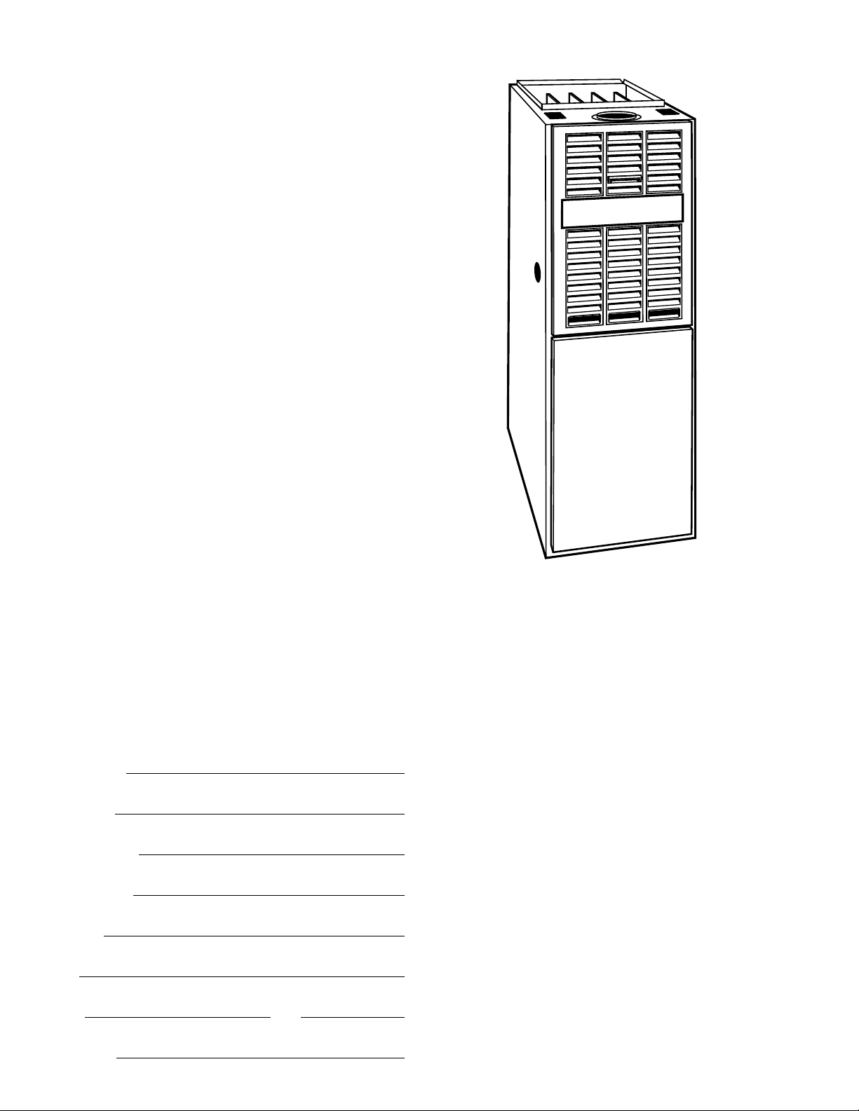
MODEL 394HAD
UPFLOW FURNACE
State Zip
T elephone
—2—
Page 3
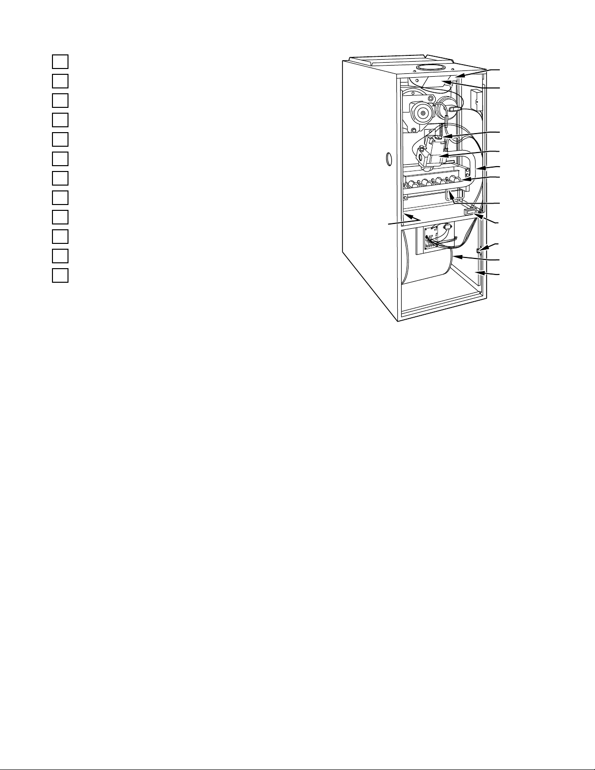
UPFLOW FURNACE COMPONENTS
1
Relief Box
2
Gas Valve Control Knob (On, Pilot, Off)
3
Gas Valve
4
Gas Burner
5
Pilot Burner and Thermocouple
6
Blower Door Safety Switch
7
Blower and Blower Motor
8
Draft Safeguard Tube and Switch
9
Rating Plate (Behind Junction Box)
10
Gas Manifold
11
Filter Retainer
12
Air Filter
8
1
2
3
10
4
5
9
6
11
7
12
2
—3—
Page 4

c
c
c
c
c
c
c
c
c
IMPORTANT FACTS
Your furnace must have adequate airflow for efficient combustion and safe ventilation. Do not enclose it in an airtight room or
“seal” it behind solid doors. To minimize the possibility of serious personal injury, fire, damage to your furnace, or improper
operation,
Keep the area around your furnace free of combustible
materials, gasoline, and other flammable liquids and vapors.
Do not cover the furnace, store trash or debris near it, or in an y
way block the flow of fresh air to the unit.
Combustion air must be clean and uncontaminated with chlorine or fluorine. These compounds are present in many products
around the home, such as: water softener salts, laundry bleaches,
detergents, adhesiv es, paints, v arnishes, paint str ippers, wa x es,
and plastics.
Make sure the combustion air for your furnace does not contain
any of these compounds. During remodeling be sure the combustion air is fresh and uncontaminated. If these compounds are
burned in your furnace, the heat exchangers and metal v ent system may deteriorate.
carefully follow these safety rules:
Untrained personnel can perform basic maintenance functions
such as cleaning and replacing air filters. All other operations
must be performed by trained service personnel. Observe safety
precautions in this manual, on tags, and labels attached to the
furnace and other safety precautions that may apply.
Recognize safety information: This is the safety-alert symbol
!
. When you see this symbol on the furnace and in instructions
or manuals, be alert to the potential for personal injury.
Understand the signal word—DANGER, WARNING, or
CAUTION. These w ords are used with the saf ety-alert symbol. DANGER identifies the most serious hazar ds which
result in severe personal injury or death. WARNING signifies hazards that
CAUTION is used to identify unsafe practices, which
would result in minor personal injury or product and prop-
erty damage.
could result in personal injury or death.
will
ST ARTING YOUR FURNACE
Your furnace is equipped with a continuously burning pilot
flame.
This manual ignition system requires the pilot to be match-lit
by hand.
A furnace installed in the attic or other insulated space must
be kept free and clear of the insulating material. Examine the
furnace area when installing the furnace or adding more insulation. Some materials may be combustible.
NOTE:
Do not use this furnace if any part has been under water .
Immediately call a qualified service technician to inspect the furnace and to replace any part of the control system and an y g as
control which has been under water.
NOTE:
The qualified installer or agency must use onl y factoryauthorized replacement parts, kits, and accessories when modifying or repairing this product.
This furnace contains SAFETY DEVICES which must be
closed. If the furnace is left unattended for an extended period
of time, have it checked periodically for proper oper ation. This
precaution will prevent problems associa ted with NO HEAT,
such as frozen water pipes, etc. See “Before You Request a Service Call” section in this manual.
SAFETY CONSIDERATIONS
Installing and servicing heating equipment can be hazardous due
to gas and electrical components. Only trained and qualified per sonnel should install, repair, or service hea ting equipment.
Read and follow the operating instructions on the furnace,
especially the item that reads as follows:
W ait 5 minutes to clear out an y gas. Then smell f or gas, including near the floor . If you smell gas,
safety information above on this label. If you don’ t smell gas, go
to the next step.
3
If a suspected malfunction occurs with your gas control system,
such as the pilot not lighting when it should, refer to the shutdo wn
procedures on the furnace or in the next section to turn of f your
system, then call your service dealer as soon as possible.
!
WARNING
Should overheating occur, or the gas valve fail to
shut off the gas supply, turn off the external manual gas valve to the furnace BEFORE turning off
the electrical supply. (See Fig. 5.) A failure to follow this warning could result in a fire or explosion,
and personal injury or death.
CHECK AIR FILTER: Before attempting to start your furnace,
be sure the furnace filter is clean and in place. (See the maintenance section of this manual.) Then proceed as follo ws:
STOP! Follow “B” in the
STEPS FOR STARTING YOUR FURNACE
Refer to the lighting instruction label affix ed to the fur nace
blower access door.
1. Set your room thermostat to the lowest temperature setting.
(See Fig. 4.)
2. Close the external manual gas valve. (See Fig. 5.)
3. Turn OFF the electrical suppl y to your furnace.
(See Fig. 6.)
—4—
Page 5

70
90
90
70
FAN
ON
AUTO
COOL
50
50
SYSTEM
OFF
HEAT
45
4. Remove the furnace access door(s). (See Fi g. 7.)
NOTE:
The blower door must be installed to permit furnace
operation.
C
L
O
S
E
ON
OFF
PILOT
89
OFF
PILOT
6
NOTE:
If pilot does not stay lit, repeat steps 5 through 9; how-
10 11
O
P
E
N
ON
OFF
PILOT
ever, hold the button down for a longer period of time (at least
90 sec). If the pilot flame is extinguished after this second attempt, the thermocouple should be checked for a possible malfunction. Call your dealer for service.
10. After the pilot flame is established, turn the control knob on
the gas valve to the ON position.
11. Replace the access doors. (See Fig. 12.)
5. Turn the control knob on the inter nal gas valve clockwise to
the indicated OFF position. W ait 5 minutes for an y expelled
gas to dissipate. (See Fig. 8.)
6. After waiting 5 minutes, open the external manual gas
valve. (See Fig. 9.)
7. Turn the control knob on the inter nal g as valve to the
PILOT position.
8. Place a lighted match or other suitable source of flame near
the top of the pilot. (See Fig. 10.)
9. Depress the button or knob and hold it do wn. The pilot will
light. Remove and extinguish the ma tch while continuing to
hold the button or knob down for at least 60 sec, then release. The pilot will remain lit.
7
12. Turn on the electrical suppl y to the fur nace.
13. Adjust the room thermostat to a setting slightly abov e room
temperature. This will automatically signal the furnace to
start.
14. Furnace main burners should light shortly after you set the
thermostat. After you verify that the burners are lit, you
may adjust the room thermostat to your own personal comfort setting. If the burners fail to light, shut down your furnace and call your dealer for service. Refer to the lighting
instruction label affixed to your furnace blo wer access door
or page 6 for shutdown procedures.
NOTE:
T o conserve ener gy when the heating season has ended,
you should shut down your manually ignited pilot. F ollow the
procedures in the “Shutting Down Y our Furnace” section of this
manual.
—5—
12
Page 6

c
SUGGESTION: Setting the thermostat back a few de grees—
and compensating for the difference with warmer clothing—can
make a big difference in your fuel consumption on extremely
cold days. The few de grees at the top of y our ther mostat “comfort level” are the most costly degrees to obtain.
When the room temperature drops below the temperature selected on the thermostat, the furnace will be switched on automatically . When the room temperature reaches the degree
selected on the thermostat, the furnace will be automatically
switched off.
Some thermostats have a “fan” switch with 2 selections: A UT O
or ON. When set on AUTO, the furnace blower cycles on and
off, controlled by the thermostat. In the ON position, the furnace
blower runs continuously except for a 45-sec dela y at the “call
for heat. ’’ This keeps the temperature level in your home mor e
evenly balanced. It also continuously filters the indoor air.
SHUTTING DOWN YOUR FURNACE
Once the heating season has ended, or if you ev er suspect a malfunction, you’ll want to turn your furnace of f. The following procedures and the procedures on the lighting/operating
instructions label on your furnace must be followed:
1. Set your room thermostat to the lowest temperature setting.
(See Fig. 13.)
2. Turn OFF the electrical suppl y to your furnace.
(See Fig. 14.)
70
50
50
SYSTEM
COOL
OFF
HEAT
3. Remove the access door(s) from your furnace. Lift up and
out at the bottom. (See Fig. 7.)
NOTE:
The blower access door must be installed to permit fur-
nace operation.
4. T o shut off the b urners but k eep the pilot light burning, turn
the control knob of the internal gas valve to the PILOT position.
5. T o shut off the complete g as control system (pilot and burners), turn (and depress if required) the control knob on the
internal gas valve clockwise to the indica ted OFF position.
6. Close the external manual gas valve. (See Fig. 5.)
7. Replace the access doors. (See Fig. 12.)
8. If the furnace is being shut down because a malfunction is
suspected, call your service dealer as soon as possible.
NOTE:
T o conserv e energy when the heating season has ended ,
you should shut down your manually ignited pilot.
If the furnace blower is to be used during the cooling season,
turn the control knob on the internal gas valv e to OFF . Leav e the
electrical supply to the furnace turned ON.
90
90
70
FAN
ON
AUTO
13 14
PERFORMING ROUTINE MAINTENANCE
With the proper maintenance and car e, your furnace will operate
economically and dependably. Basic maintenance, which can
easily be accomplished by following the directions, is found on
this and the following pages. Ho wever, before beginning maintenance, follow these safety precautions:
!
WARNING
TURN OFF ELECTRICAL POWER SUPPLY TO
YOUR FURNACE BEFORE REMOVING THE ACCESS DOORS TO SERVICE OR PERFORM MAINTENANCE. A FAILURE TO FOLLOW THIS WARNING
COULD RESULT IN PERSONAL INJURY OR DEATH.
!
CAUTION
ALTHOUGH SPECIAL CARE HAS BEEN TAKEN
TO MINIMIZE SHARP EDGES, BE EXTREMELY
CAREFUL WHEN HANDLING PARTS OR REACHING INTO THE FURNACE.
FILTERING OUT TROUBLE
A dirty filter will cause excessive stress on the furnace blower
motor and can cause it to overheat and automatically shut do wn.
The furnace filter should be checked ev ery 3 or 4 w eeks and
cleaned if necessary.
If your furnace filter needs replacing, be sure to use the same
size and type of filter that was originally supplied. Use the furnace filter table (see page 7) and compare your furnace size with
the proper filter size.
!
CAUTION
NEVER OPERATE YOUR FURNACE WITHOUT A
FILTER IN PLACE.
Doing so may damage the furnace blower motor.
An accumulation of dust and lint on internal parts
of your furnace can cause a loss of efficiency.
The air filter for upflow furnaces is normally located in the
blower compartment. If the filters ha ve been installed in another
location, contact your dealer for instructions. To inspect, clean
and/or replace the air filter(s), follow these steps:
UPFLOW FURN ACES ONLY:
1. Turn OFF the electrical suppl y to the furnace. (See Fig. 14.)
2. Remove control and blow er access door s.
3. Push filter retainer toward the bracket opening to r elease
the filter. (See Fig. 15.)
4. Gently remove the filter and carefully turn the dirty side up
(if dirty) to avoid “spilling’’ dirt from the filter.
(See Fig. 16.)
15 16
—6—
Page 7

5. Inspect the filter . If torn, replace the fi lter.
6. W ash the filter (if dirty) in a sink, bathtub, or outside with a
garden hose. Always use cold tap water. A mild liquid detergent may be used if necessary. Spray water through the
filter in the opposite direction of airflow (through the crossmesh binding side). Allow filter to dry.
7. Reinstall the clean filter with its cross-mesh binding side
facing the furnace blower.
8. Put filter retainer back in the bracket opening and lock it in
place.
9. Replace the blower and control access doors and turn ON
electrical power to your furnace. (See Fig. 12 and 17.)
NOTE:
If side return ducts are used, two filters may be required
in some models. The procedure listed abov e may be used to remove side filters.
*
M
M
M
M
NOTE:
your servicing dealer. DO NOT OPERATE THE FURNACE.
If dirt, rust, soot, or scale accumulations are found, call
3. Inspect the vent pipe for a sag, holes, or a disconnection. A
horizontal vent pipe must slope upward. If rusty joints or
seams, or signs of water leakages are found call your dealer
for service.
!
WARNING
If holes are found—or if the vent pipe is obstructed
or is not connected—toxic fumes can escape into
your home. DO NOT OPERATE YOUR FURNACE.
Call your dealer for service. A failure to follow this
warning could result in personal injury or death.
18
17
COMBUSTION AREA AND VENT SYSTEM
Inspect the combustion area and vent system bef ore each heating
season. An accum ulation of dirt, soot, or rust can mean a loss of
efficiency and improper performance. Buildups on the main
burners or pilot assembly can cause faulty firing. This “delayed
ignition” is characterized by an alarmingly loud sound. If your
furnace makes a loud noise when the main burners are ignited
by the pilot, shut down the furnace—call your servicing dealer.
Refer to the lighting instructions label on the blower door f or
shutdown procedures.
UPFLOW FURNACE FILTER TABLE
FURNACE
CASING
WIDTH
14-3/16 (1) 16 x 25 x 1 * (1) 14 x 25 x 1 * Cleanable
17-1/2 (1) 16 x 25 x 1 * (1) 16 x 25 x 1 * Cleanable
21 (1) 16 x 25 x 1 * (1) 20 x 25 x 1 * Cleanable
24-1/2 (2) 16 x 25 x 1 * (1) 24 x 25 x 1 * Cleanable
Factory provided with the furnace. Filter may be field modified by cut-
ting as required. Alternate sizes and additional filters may be ordered
from your dealer.
Use your flashlight and follow these steps for inspecting the
combustion area and vent system of your furnace:
1. Turn of f the electrical supply to the furnace and remo ve the
access doors. (See Fig. 6 and 7.)
2. Carefully inspect the gas burner (See Fig. 18) for dirt, rust,
or scale. Then, inspect the relief box, flue connection area,
and the vent pipe for rust.
FILTER SIZE
FIL TER TYPESide Return Bottom Return
4. Replace the access doors and restore electrical power to the
furnace. Be sure bottom door flange is inside of the furnace
casing. (See Fig. 12 and 17.)
5. Start the furnace and observe its operation. If possible,
watch the burner flames. Are they burning bright blue? If
not (or if you suspect some other malfunction), call your
servicing dealer.
BEFORE YOU REQUEST A
SERVICE CALL
BEFORE Y OU CALL FOR SERVICE, CHECK FOR
SEVERAL EASILY SOLVED PROBLEMS:
Check for sufficient airflow. Check the air filter for dirt.
Check for blocked return-air or supply-air grilles. Be sure they
are open and unobstructed. If this isn’t the cause, call your servicing dealer.
If your furnace isn’t operating at all, check the following list for
easily solved problems:
Is your thermostat set above room temperature? Is the
switch in the HEAT position?
Is the electrical power supply switch ON? Is the blower
access door firmly in place? Are any fuses blown—has a
circuit breaker tripped? (There is a fuse on the furnace control
board.)
Is the manual shut-off v alv e in the g as supply pipe leading
to the furnace open? Does the lev er point in the same dir ection
that the pipe runs (open)? Or is it at right angles (closed)?
NOTE:
Before proceeding with the next checks, turn OFF the
electrical power supply to the furnace. Remove the control access door. The blower access door must be installed to permit
furnace operation. On downflo w furnaces, the blower access
door must be removed before the control access door is remo ved,
then reinstalled.
—7—
Page 8

M
M
M
M
Is the control knob on the gas valv e turned to the ON position? If this or the preceding check shows an interruption in the
gas supply, make sure the gas has not been shut off for safety
reasons.
Check for pilot flame. If there is no pilot flame, follow the
manual start-up procedures or the furnace lighting instruction
label. If the pilot flame exists, check the control knob on the gas
valve. If the knob is in the PILOT position, turn it to ON and
complete the start-up procedures.
If for some reason the vent is blocked, the draft safeguard
switch will shut off the furnace. Reset the switch by pushing
the button located on top of the switch (see page 3 for switch
location).
If the switch trips a second time, turn off the furnace and call for
service.
If your furnace still fails to operate, call your servicing
dealer for troubleshooting and repairs. Tell them the model and
serial numbers for your furnace. (You should have them recorded on page 2 of this booklet.) If the dealer knows exactly
which furnace you have, they may be able to offer suggestions
over the phone, or sa ve valuable time through knowledgeable
preparation for the service call.
REGULAR DEALER MAINTENANCE
In addition to the type of routine maintenance you might be willing to do, your furnace should be inspected regularly by a properly trained service technician. An annual inspection (or every
other year, at least) should include the following:
1. Inspection of all flue product passages—including the
burners, pilot and pilot tube, heat exchanger , relief box, and
vent pipe.
2. Inspection of all combustion and ventilation air passa ges
and openings.
3. Close check of all gas pipes leading to (and inside of) your
furnace for leaks and/or deterioration.
4. Inspection, cleaning, and lubrication (when required) of the
blower motor and wheel.
NOTE:
Refer to the unit service procedures for blower motor
oiling information. When required, the motor must be oiled by
a qualified service technician.
5. Routine inspection and cleaning/replacement of the air filter(s).
6. Inspection of all supply- and return-air ducts for obstructions, air leaks, and insulation. Any problems found should
be resolved at this time.
7. A check for loose connections attaching individual components. Inspection of all electrical wiring and their connections.
8. Operational check of the furnace itself to determine working condition. Repair or adjustment should be made at this
time.
9. Check the physical support around the furnace base for
cracks, gaps, sagging etc. Ensure there is a good air seal
between the furnace and support.
10. Check burner and pilot flames. Compare flames to Fig. 18
for proper operation.
Y our servicing dealer of fers an economical service contract that
covers seasonal inspections. Ask him for further details.
1995 BDP Co. Indpls, IN 46206 Printed in U.S.A.
—8—
®
Cancels: OM04-10 OM04-22
Catalog No. BDP-3339-437 10-95
 Loading...