

Page 1
394
Installation Instructions
GAS FIRED FORCED AIR FURNACE
Introduction
Before installing the furnace, refer to Bryant Form
No. 39003D1 “Procedure for Gas Appliances”
(packaged with the equipment) for information con
cerning combustion, venting, piping, and other standard
installation practices. Further reference is made to the
current edition of the American Standard “Installation
of Gas Appliances and Gas Piping,” ASA Z21.30.
Model 394 Gas Furnaces are shipped from the factory
completely assembled and wired ready for indoor
upflow heating installation. They are manufactured
with two types of blowers: belt and direct drive. The
three smaller sizes (Series F), 50, 80, and 100, are
direct drive only. All sizes incorporate a low-voltage
terminal strip for convenience of field wiring.
The optional equipment available includes: Counterfiow Box, Side and Rear Drop Ducts; Side Filter
Racks, Cooling Coil Housing, Combustible Floor
Base Packages, for Counterfiow Applications, Cooling
Relay Kit for field conversion.
Note: Do not use Cooling Relay Kit with 3/4-HP
Blower Motor sex Drive Models.
CAUTION:
1. Counterflow furnace must be installed on an ap
proved non-combustible base.
2. Be sure temperature rise does not exceed that
specified on the unit rating plate.
3. Be sure to check all controls for proper operation
upon completion of installation.
I. CLEARANCE REQUIREMENTS
The upflow furnace is certified for use on combustible
floors.
The furnace is certified by the American Gas Asso
ciation, Inc., for installation in a closet or alcove
provided the following clearances from combustible
construction are maintained:
Sides
............................................................
Back.............................................................0" (1")*
Top of Plenum
Vent Connector............................................6" (6")*
Front
............................................................
*Figures shown in parentheses are approved clearances
when the furnace is installed as a counterflow furnace.
.............................................
0" (1")*
3" (0")*
6" (6")*
Series F
Sizes 50 thru 220
bruant
Cancels ^39№31
II. CONTROLS
Bryant Automatic Gas Control Valve
If not already checked when lighting the main burner,
check the proper operation of this valve by moving
the room thermostat pointer above and below room
temperature and observing that the main burners light
on call for heat and go off when the pointer is moved
below the room temperature setting. All Bryant auto
matic gas control valves have a delay of approximately
15 to 30 seconds.
Automatic Pilot
To check the pilot operation, follow the instructions
below:
1. Set the room thermostat on call for heat. (There
is a delay before burners light.)
2. After the burners light, shut off the pilot gas valve.
3. After the pilot is out, the monometal element cools
and returns to the open position. This breaks the
circuit to the gas valve and the burners will extinguish.
Pilots with Thermocouple Elements
The D2 100% shutoff propane and D5 100% shutoff
natural gas controls have pilots equipped with thermo
couple elements.
The pilot flame should surround the tip of the thermo
couple. It should also extend downward to include
3/8 to 1/2 inch of the thermocouple tip. The flame
must not come in contact with any other part of the
thermocouple.
D2 Propane
The thermocouple transforms heat energy from the
pilot flame into electrical energy. The current thus
generated is sufficient to operate the 100% inline
shut-off valve. The Bryant diaphragm gas control valve
is powered externally from the transformer, and
operates independently of the inline shut-off valve.
When there is a pilot flame, the current generated by
the thermocouple holds the 100% inline shut-off valve
in the open position and the gas control valve controls
the flow of gas. Should the pilot go out, no current will
Page 2
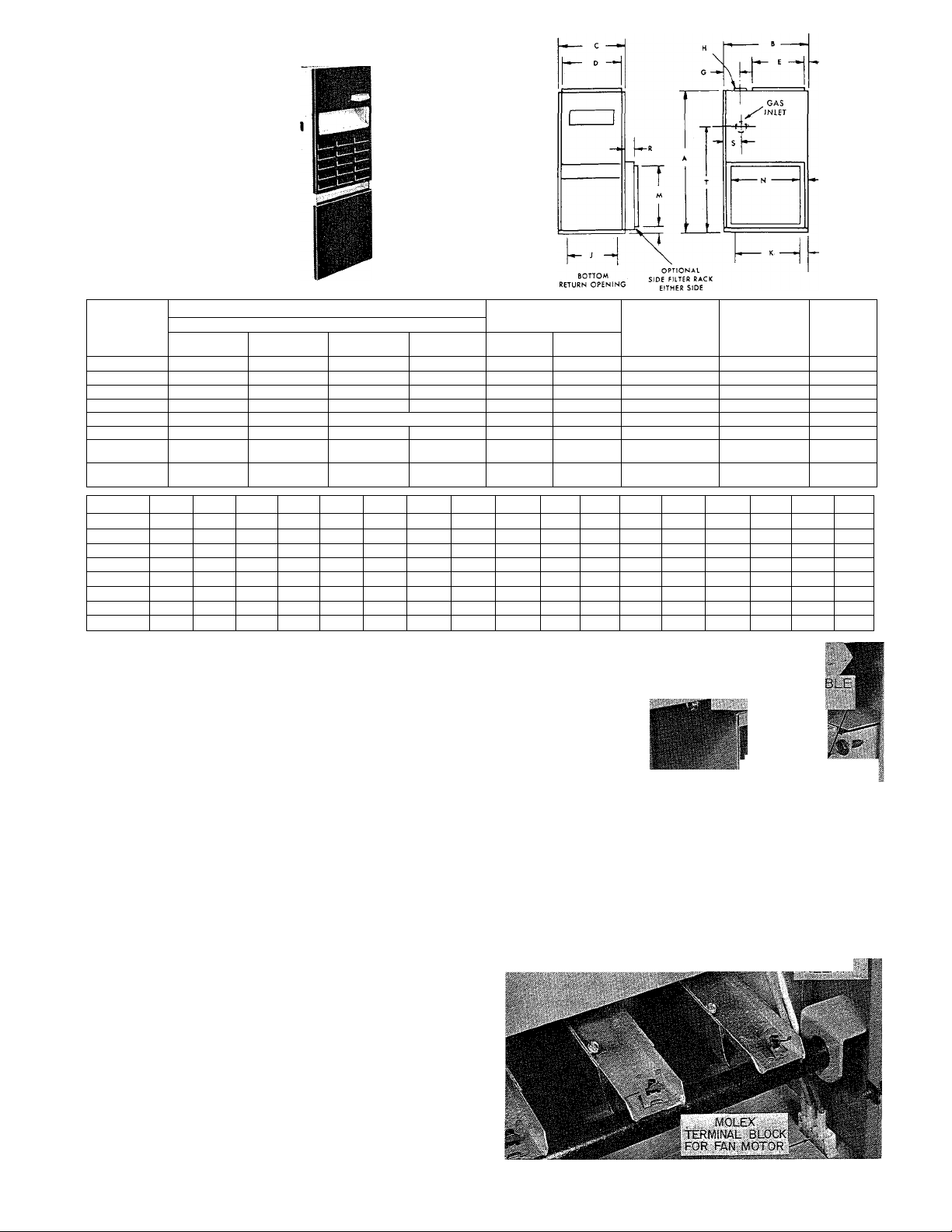
UPFLOW
FURNACE
A.G.A. RATINGS BTU/HR
Modet
No.
50-394 50,000
80-394 80,000
100-394 100,000
125-394
1 37-394
165-394 165,000 132,000
190-394 190,000 152,000
220-394 220,000 176,000
Model No.
50-394 46 26
80-394
1 00-394
125-394 46 26 20'4 18%
137-394 46
1 65-394
190-394 51
220-394
1 nput
125,000 100,000 1 25,000 100,000
137,500 11 0,000 Not available
A В C
46 26 16 1/4
26 18'/4
46
26
51
28У4
283/4
51 283/4
16'/4
20'A
2 81/4
36У,
361/4
Natural Propane
Bonnet
Capacity Input
40,000 50,000 40,000
64,000 75,000 60,000
80,000
D E
14=/8 20
14%
165/g
18% 20
26%
34%
343/s
20
20
20
173/4
173/4
173/4
100,000
150,000
175,000
200,000
F
%
'/2
%
'/2
%
2/2
2%
2%
Bonnet
Capacity Natural
120,000
140,000
160,000
G
2V,
23/4
23/4 5" 14%
23/4
23/4
5
5 (2) 5" •
5 (2) 5"
*Both Sides
be generated by the thermocouple and the 100% inline
shut-ofF valve will close. No gas can then flow to the
pilot.
GAS CONNECTION
SIZES
'Л '/2
4"
12/4
4" 12'/4
5"
18%
5" 18%
25%
6"
'/2 '/2
'/2 '/2
'/2 /2
'/2
'Л ’/2
'/2 '/2
'/2 '/2
80,000
H J К L M N P
33%
33%
Propane
'/2
22%
22%
22%
22%
22%
23%
23%
23% 2%
l'/2
l'/2
l'/2
l'/2
l'/2
23/8
23/8
Bottom
14 X 25 X 1 14 X 25 X 1 135
14 X 25 X 1
16 X 25 X 1 16 X 25 X 1
20 X 25 X 1 20 X 25 X 1
20 X 25 X 1 20 X 25 X 1
(2) 14 X 25 X 1 (2} 16 X 25 X 1
0) 16 X 25 X 1
(1) 20 X 25 X 1 (2) 16 X 25 X 1
(1) 16 X 25 X 1
(1) 20 X 25 X 1
12 23
1 2 23
1 4
1 8
1 8 23
23
23
23
Filter
Sizes
Side
Filter
Sizes
14 X 25 X 1 153
(2) 16 X 25 X 1
R s T
2
1 %
2
1 %
23
23
24
24
24
1 %
1%
1 %
2% 8%
2%
2'/e
2
2
2
8%
8У2
Approx.
Shipping
Weight
178
200
202
282
365
365
*333/8
3%
*333/8
3%
*335/8
ЗУ2
*33%
ЗУ2
*333/8
3V2
4 30'3/4
4
30'3/i
4
30'3/i
D5 Natural
Should the pilot go out, no current will be generated
by the thermocouple and the pilot-relay will close,
shutting oiF the gas to the pilot, and breaking the elec
trical circuit to the Bryant automatic gas control valve.
821/822 Adjustable Fan Control
The Model 394 Furnace incorporates the 821/8.22
relay for fan control. (The 821 relay is used with the
643 gas valve on furnace sizes 50 through 165; the 822
relay is paired with the 641 valve on sizes 190 and 220.)
The 821/822 has a field-adjustable differential. The
“max off’ setting on the dial is for the longest “off’
time and shortest “on” time.
When facing the front of the furnace, the “off’ cycle
is lengthened by moving the adjustment lever to the
left. The “off’ cycle is shortened by moving the lever
to the right. The adjustment of the “off’ cycle has the
opposite effect on the “on” cycle; however, to a lesser
degree.
39394D41
-RMiXAL 'R - 3^.
Ш 8?1. 622
^ T VE
DEL-iY
■ '!• PPI
Figure 1 - Control Box, Installed View
^ '»J
Page 3

BASEMENT
FURNACE
A.G.A. Ratings BTU/HR
Model
No.
Input
50-394
80-394
100-394 100,000 80,000
125-394 125,000 100,000
137-394
165-394
190-394
220-394
50,000
80,000
137,500 n 0,000
165,000
190,000
220,000
Natural Propane
Bonnet
Capacity
40,000
64,000
132,000 150,000
152,000
176,000
Bonnet
Input
50,000
75,000
100,000
125,000
175,000 140,000
200,000 160,000
Capacity
40,000 46
60,000
80,000
100,000
Not available 46
120,000
A В
40'Л
46
40'Л
46
40'Л
46 40 Уг
40’Л 2054 13Н
51
43 54
51
4314 36'А
51
43 54
D Е
С
20
иУв
1654
1б'Л иУв
18Й
20Й
2 8'/4 26Уа 17% 4'Л
3654
20
20
1 бУа
20
1 ^Уа
20
34Уа 17% 4'Л
34Уа
17%
F G Н
2'Л 2%
2%
2'Л
2%
2Уг
2%
2'Л
2%
2'Л
4'Л
5
5 2-5"
4'Л
2-5"
J к
4"
533Уа
4"
533Уа
5"
|ЗЗУа
5"
533Уа
5"
t33ya
Ь"
ЗО'Уа 4
ЗО'Уа
30'5/й
Gas Connection
З'Л 54
з'Л
з'Л
З'Л
З'Л
4
4
Sizes
Nat.
54 Уа
'Л
54 Уа
Уа Уа
Уа Уа
Уа
Уа Уа
Filters
Prop.
Уа
Уа
Уа
14 X 25 X 1 166
1 4 X 25 X 1
1 6 X 25 X 1
20 X 25 X 1 238
20 X 25 X 1
Two 1 6 X 25 X 1
Two 1 6 X 25 X 1
Two 1 6 X 25 X 1 428
Ratings are certified for altitudes to 2,000 feet for all gases. Ratings for altitudes over 2,000 feet are 4% less for each 1,000 feet above sea level.
Return air compartment shipped separately, knocked down.
tBoth Sides.
COUNTERFLOW
18% 100 SIZE
16% . 50 & 80 SIZE
FURNACE
Approx.
Shipping
Weight
(Lb.)
192
213
240
343
428
It OUTLET
A.G.A. RATINGS BTU/HR
Model
No.
50-394 50,000
80-394
100-394 100,000
125-394 125,000
137-394 137,500
165-394 165,000
190-394 190,000
220-394 220,000
Input
80,000
Capacity
Natural Pro pane
Bonnet
100,000
1 10,000
132,000
152,000
176,000 200,000 1 60,000 80 28% 36% 34%
Input
50,000
40,000
75,000
64,000
100,000 80,000 75 26
80,000
125,000
150,000
175,000
Bonnet
Capacity
40,000
60,000
1 00,000
Not available 75 26 20% 18%
1 20,000
1 40,000 80
В C 0 E
A
75 26
75 26
75 26
80 28%
28% 36% 34%
*Add 114” when installed with base on combustible floor.
tBoth Sides.
**See above “CS” Drawing for Dimensions (50-80-100 Sizes Only).
TYP'E "C" dimensions
16Й 14%
14%
16(4
18У4 16%
18%
20(4
28
26%
F G H J К
4" 12% 22%
2%
2%
2%
2%
2%
4'/a
5 (2) 5" 33%
5
12%
4"
14%
5"
S" 18% 22%
18%
5"
25%
6"
33% 23%
(2) 5”
22%
22%
22%
23%
23%
I'/a
1Уа
I'/a
I'/a
I'/a
1Уа
1Уа
1Уа
L
t33ya
ЗУа
t33ya
ЗУа
ТЗЗУа
ЗУа
t33ys
ЗУа
|ЗЗУа
ЗУа
4 301 У.
4 ЗО'У.
4
ЗО'Уа
*
L
TLET I
GAS CON.
SIZES
Nat. Prop.
Уа
Уа Уа
Уа Уа
Уа Уа
Уа Уа
Уа Уа
Уа Уа
Уа Уа
Filters
16x20x1
Уа
16 X 20 X 1
Two 1 0 X 20 X 1 210
Two 1 4 X 20 X 1
Two 1 4 X 20 X 1
Two 1 6 X 20 X 1
Two 20 X 20 X 1
Two 20 X 20 X 1
Approx.
Shipping
Weight
(Lb.)
166
185
235
237
325
405
405
39394D41
Page 4

TO HEATINQ AND
I COOLING CONNECTIONS
VOF THERMOSTAT
( P/N 34427D030
34427D03Ì
I
TO CONDENSER
CONTACTOR COIL
CONNECTIONS
TO HEATINS AND
COOLING CONNECTIONS
^OF THERMOSTAT
' P/N 34427D030
a 344270031
-, ' TO CONDENSER
- I LOW VOLTAGE
■ " ' —ALEAD OR
NOTE^
WIRE WITH* IN FIGURE 2 IS
REMOVED AND DISCARDED WHEN
CONDENSER HAS TRANSFORMER.
^ J TERMINAL STRIP
Figure 2 - Control Box, Cover Removed,
No Internal Wiring Changes
Low-Voltage Wiring
Field low-voltage connections are made at the low-
voltage terminal strip. See Figure 6 for heating only.
For Model 394 Furnaces used in conjunction with
electric or gas air conditioning units that do not have
an integral transformer, see Figure 2. If the 394 Fur
nace is used in conjunction with an electric or gas air
conditioning unit having an integral transformer, see
Figure 3.
Figure 3 shows a field-installed wire running from
one side of the air conditioning transformer, through
the hole marked “F” in the terminal strip to the blower
relay in the control box for the Model 394 Furnace.
The wire marked * in Figure 2 is removed from the
control box and discarded.
Limit Control
This control shuts off the gas and energizes the blower
motor if the furnace becomes overheated.
The recommended method of checking the limit control
is to gradually block oif the return air after the furnace
has been operating for a period of at least five minutes.
As soon as the limit has proven safe, the return air
opening would be unblocked to permit normal air
circulation. By using this method to check the limit
control, it can be established that the limit is function
ing properly and will “fail-safe” if there is a motor
failure.
Figure 3 - Control Box, Cover Removed,
Showing Internal Wiring Changes
Thermostat Location
The room thermostat should be located where it will
be in the natural circulating path of room air. Avoid
locations where the thermostat would be exposed to
cold air infiltration, drafts from windows, doors, or
other openings leading to the outside, or exposure to
air currents from warm or cold air registers; or to ex
posure where the natural circulation of the air is cut
off—such as behind doors, above or below mantels,
shelves, etc.
The thermostat should not be exposed to heat from
nearby radiators, fireplaces, radios, televisions, lamps,
or rays from the sun. Nor should the thermostat be
mounted on a wall containing pipes or warm air ducts,
or a flue or vent which could affect its operation and
prevent it from properly controlling the room tempera
ture. Any hole in the plaster or panel through which
the wires pass from the thermostat should be adequately
sealed with suitable material to prevent drafts from
affecting the thermostat.
The heat anticipator on the thermostat should be set
at 0.8 amps.
III. ELECTRICAL CONNECTIONS
Line-Voltage Wiring
All electrical connections are to be made in accordance
with the local electrical codes. A permanent, live,
separately fused electric power supply, complete with
manual switch, should be provided for the furnace.
Field wiring connections should be made in accordance
with the internal wiring as shown in Figure 6; select
the appropriate combination of diagrams to match the
equipment being used.
>41 39394D41
Page 5

Adjustment of Blower Speed
Four-Speed Direct Drive
To change motor speed taps, remove the motor tap
lead (see Figure 1) and relocate it on the desired ter
minal on the plug-in terminal block/speed selector
located on the dividing panel. See Table I.
Belt Drive
The blower speed may be changed by opening or clos
ing the motor pulley. When adjusting blpwer speed,
be certain that both pulleys are adjusted the same
number of turns.
CAUTION: When adjusting the blower speed, make
certain that the temperature rise across the heat ex
changer does not exceed that specified on the rating
plate.
TABLE 1 - Factory Setting Blower Motor Chart
Drive Type
Unit
Size
50
80
100 2
125
137
165
190
220
SL
Red
to
RI
3 1
2 1
Blue
to*
1
sM SE
Red
Blue
to
to
1
4
3 1
Red
BluetoRedtoRed
to
4 1
4 1
4 1
3 1 1
2 1
2 1
SB
1 1
1 1
1 1
1
to
1
1
sc
sex
Red
to
1
1
1
1
1
1
*Use when relay kit is field installed.
IV. CARE AND MAINTENANCE
Cleaning
The heat exchanger should be examined periodically
to see if there has been an accumulation of rust, soot,
etc. Clean as follows:
1. Disconnect pilot tubing at tube union.
2. Disconnect electrical lead from pilot. (In case of
100% shut-off controls, disconnect pilot thermocouple
lead from pilot relay or inline shut-off valve.)
3. Remove front plate from draft diverter (4 sheet-
metal screws).
4. Remove burners and pilot as follows:
a. Remove Tinnerman clamp from burner-holding
stud.
b. Slide burner off orifice and remove under
manifold.
c. Pilot is attached to one burner and is removed
with that burner. It is not necessary to detach
pilot before removing burner.
5. Remove metal angle strip holding flue baffles in
place. See Figure 4.
6. Remove flue baffles. See Figure 5.
7. Use flexible-handled steel cleaning brush to loosen
scale and soot. Remove scrapings from bottom of
combustion chamber.
combustion chamber.
8. Reassemble furnace by reversing above procedure.
NOTE: There is a slot in the back of the heat ex
changer for the back tip of the burner to fit into. When
properly placed, the burner will fit into this slot and
will be level.
Color Code for Speed Taps
Common (white)
Hi Speed (black)
.........................................................
..........................................................
#C Tap
#1 Tap
Med Speed (blue).........................................................#2 Tap
Med-To Speed (yellow)
Lo Speed (red)
.............................................................
...............................................
#3 Tap
#4 Tap
Care of Blowers
All motors on the belt drive blowers are provided with
oil cups and should be oiled at least twice a year with
a nondetergent SAE 30 oil.
Figure 4-Flue-Baffle Retainer Strip
Figure 5-Removing Baffles
39394D41
Page 6

Belt Tension
Adjust tension on a V-belt so that the belt deflects
approximately 3/4 to 1 inch when the pressure from
one finger is applied midway between the blower and
motor pulleys. Adjust the tension by turning the motor
adjusting screw.
LINE VOLTAGE GRCUIT
BLK.
120V / , .
, - DIRECT DWVECsO
/NO CAPACITOR used')
VON DIRECT DRIVE/
BLK.
4 SPEED ^ ^
REB
FAV4
CONTROL
i a 141
WHITE Y ®
StE CHAHT^ t
LOW VOLTAGE CIRCUIT
BKOWN
UPPER UM\T /0\
COUMTERPUOWViJ/
PW-OT
safeW
SWITCH
Í (bMIT
OVl
prop)
9
BLK
BLK
^ % H.R,(SCX), DRIVE FURVIACE
15 F^CTORY WIRED FOR 230V.
POWER. IF ONLY 120V, POWER
IS AVAILABLE, RED WHITE
WIRES MUST BE REVERSED
AT THE TRANSFORMER. SEE
\W1R\NG LABEL ON DUAL.
CIRCUIT MOD\F\E¿ BY COOÜ>A RELA^V (S.P.O.X)
STAV4DAR0 ON SMASE \t\.D''INSrT^ULBD
ON SL DRIVE..
______________
VOLTAGE MOTOR FOR
IZOV. CONNE.CT\OV4.
©in i V i
writeY
BLK.
CIRCUIT MODIFIED BY COOLING
RELAY <;s.P,D.T.)'TlELO” INSTALLED ON
SB.se 4 VeH.P. sex DRIVES
whiteY 51
230V.+
10 ^
FAN
eONTROl
SEE CHART
(RED)
BELT DWVE
ILL SB, SO ^
SOX lfeH.P.
_________________
li sIvJl 4Í
S.P.S.T, \
CDOLiwa X
RELAY WHITES
J ■'field n
7 INSTALLED
BELT DRIVE
; sex ONLY
(V4H,P.)
RED
/
9
:
FACTORY SETTING CHART
UNIT
size:
.50
80
lOO
I25
I37
1G5
\90
220 \
VALVE
FAN CONTROL
m
S
RED
TO
—
—
2 I
3
2
— ■
—
BLUE
Filters
Some units are equipped with a permanent fiber filter
(recognizable by its distinct green color). To clean this
filter, run water through the fibers from the entering
air side. Do not spray this filter with water-soluble oil.
THERMOSTAT COtmECTlONS
-HEATING ONLY-
(necD WRms is iwtcwa k wanco uwa)
SLUE
T) WRITE
BLK.
GREEN
WREN USED
7*W
J
DIRECT DRIVE TYPES
SLjSMB SE
BELT DRIVE TYPES
SB, SC $ sex
THERMOSTAT BN 34427035 (noTERMINAL code), also MODELS
883-P/N 344270030 OR 884-
P/N 34427D03I THERMOSTAT 4
SUB BASE.
note; remove inter
W
nal JUMPER BETWEEN
"I W 4 J TERM\NALS.
----------------
MAIN
LIMIT
COOLIN« RELAY
J
4
G
X
DRIVE
5
REDTOBLUETOREDTOSUiE
TO*
—
4
—
— —
—
I
—
I
— — —
—
I
I
3
—
—
—
—
*USE WHEN FACTORY REUCY KIT IS “FIELD" INSTALLED.
Y ^
F n TYPE SL,SM4SE
P/N 34427D33 THERMOSTAT
4 SUB-BASE OR THERMOSTAT
MODEL SaS P/n 3442.7MS WITH SUB
BASE P/N3442703i.
4
4
4
3
2
2
— —
DIRECT DRIVS^
BELT DRIVE
TYPE SB, SC 4 sex
ON-OFF FAN, MODEL S85
s
E
TO
I
SB
RED
(
I
I
I \
I
TO
—
sc
sex
TO
I I
\
\ \
I
I
—
RED
TO
REO
— — —
— — —
I
I
I
\
I
\
\
39394D41
Figure 6 - Internal Wiring
 Loading...