

Page 1
393U
Installation Instructions
GAS FIRED FORCED AIR FURi^ACE
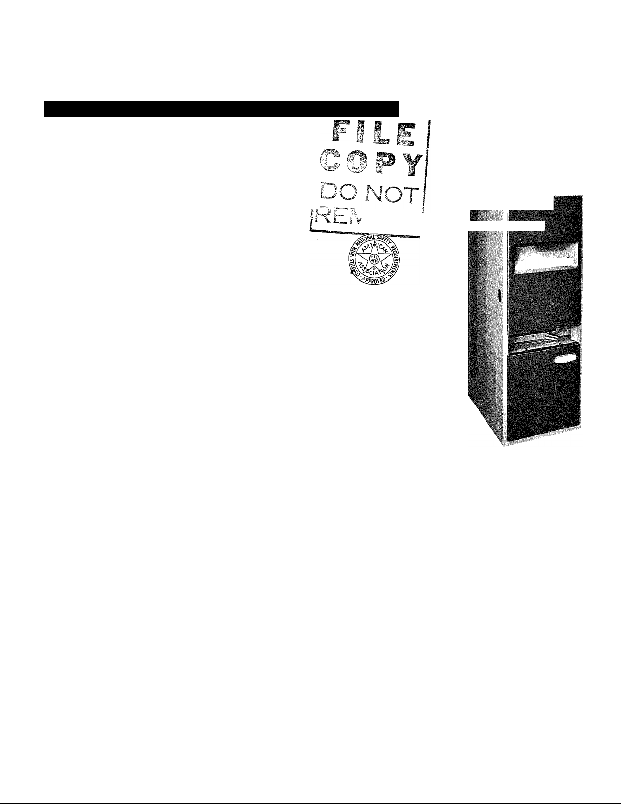
The Bryant Model 393 forced air, gas-fired furnace
may be installed as an
1.2.Upflow Furnace
Counter-Flow Furnace
(except sizes 175 and 200)
Basement Furnace
This instruction contains complete procedures for
installing the unit as an Upflow Furnace.
When the furnace is used as a counter-flow, a
counter-flow box and instructions are provided.
When it is used as a basement model, a drop duct
and instructions are provided. The Series C and D
Counter-Flow Boxes are interchangeable.
/1 \ fr
"iKJ V fl
Series D
39393D2
I
Rev. 3/17/65
Before beginning installation, read these instruc
tions carefully.
When making a Counter-Flow or Basement installa
tion, also read the separate instructions furnished
with the additional equipment required.
install the furnace in accordance with the require
ments of the local utility or authority having juris
diction.
The installer is referred to the American Standard
“Installation of Gas Appliances and Gas Piping,”
ASA Z21.30-1964, as a sound and practical guide
to be followed when making the installation.
INSPECTION
Check the power supply available to be sure it
agrees with the information on the wiring diagram
and the blower motor in the furnace.
Check the gas specification on the A.G.A. rating
plate to be sure that the type of gas for which the
unit is equipped is the same as the gas supply
available.
Model 393 Furnace
FILTERS
When the furnace air distribution system is used for
cooling, it is recommended in certain instances that
the throw-away filters be discarded and the perma
nent type, multi-velocity filters be substituted. The
following table gives the air flows above which
these high velocity filters should be used.
Size
80
100 1000
125
150
175
200
Air Flow - cfm
800
1240
1490
1800
1800
Leave these instructions on or near the furnace. Permanent filters are not required on Size 50.
Page 2
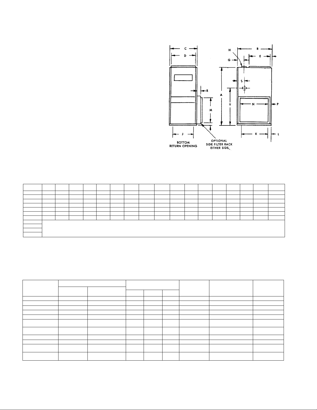
UPFLOW
FURNACE
Model No.
50-393 46 26 16% 14% 20
80-393 46
100-393 46 26 18% 165% 20
125-393 46
150-393
175-393 51
200-393
250-393
300-393
350-393
400-393
A
51
•28%
■ 51 28%
MODEL
NO.
50-393 50,000
*80-393 !
100-393 100,000
125-393
150-393 150,000
175-393 175,000 140,000
200-393 200,000 160,000
250-393 250,000
300-393
350-393
400-393
The 250, 300, 350 & 400 sizes are multiples of the 1 25, 1 50,
*For LP Gas, ModeJ Designation 80-V-393, A.G.A. Input 75,000,
283% 36%
Sizes 250 thru. 400 are multiples of sizes 125, 150, 175 and 200 respectively. Refer to the dimensions of smaller sizes to obtain overall’ dimensions for the
larger sizes. Provide clearance dimension between units for gas service and casing expansion. Refer to installation instructions for clearance.
C D E F G H
В
26 16%
26 20%
INPUT
*80,000
125,000
300,000 240,000
350,000 280,000
400,000 320,000
145% 20
185% 20
265%
28%
345%
345% 173%
36%
A.G.A. RATINGS BTU/HR GAS CONNECTION
23%
1%
23%
1%
3
1%
3 5" 18%
BONNET
40,000
64,000
80,000
100,000
120,000
200,000
'%
53%
2'%
43% (2)5" 33%
2'%
43% (2)5" 33%
21%
'%
1% 1% 1/2
'%
'%
% % %
%
% % %
(2) 1%
(2) % (2) 5%
(21 % (2) % (2) %
(2) %
175 & 200 respectively.
Bonnet Capacity 60,000.
173%
173%
CAPACITY NAT.
J К
4" 12% 22%
4" 12%
5"
6" 25%
SIZES
MFD. Prop.
. '/2
’% '%
% 1/2
% %
(2) % (2) 1/2
(2) % (2) %
22%
14% 22%
22%
23%
23% 25%
23% 25%
1%
(2) %
L M N P
23
12
1%
12 23
1%
14 23
1%
18 23
11%
25%
23
23
23
BOTTOM FILTER
SIZES
14 X 25 X 1
14 X 25 X 1
16 X 25 X 1 1 6 X 25 X 1
20 X 25 X 1
(2) 14 X 25 X 1 (2} 16 X 25 X 1
(1} 16 X 25 X 1
(1) 20 X 25 X 1
(1) 16 X 25 X 1
(1) 20 X 25 X 1
(2) 20 X 25 X 1
(4) 14 X 25 X 1
(2} 16 X 25 X 1
.(2) 20 X 25 X 1
(2) 16 X 25 X 1
(2) 20 X 25 X 1
24
24
24
SIDE FILTER
SIZES
14 X 25 X 1
14 X 25 X 1
20 X 25 X 1
(2) 16 X 25 X 1
(2) 16 X 25 X 1
(2) 20 X 25 X 1
[4} 1 6 X 25 X 1
[4} 1 6 X 25 X 1
(4) 16 X 25 X 1
1%
1%
1%
2% 8%
2%
2'%
R s
23%
2
1%
2 23%
2 23%
23%
2
4 30%
8% 4
8%
4
APPROX.
SHIPPING
WEIGHT
135
155
178
200
275
355
355
400
550
710
710
27%
27%
27%
27%
30%
30% .
t
393U
-2-
Page 3
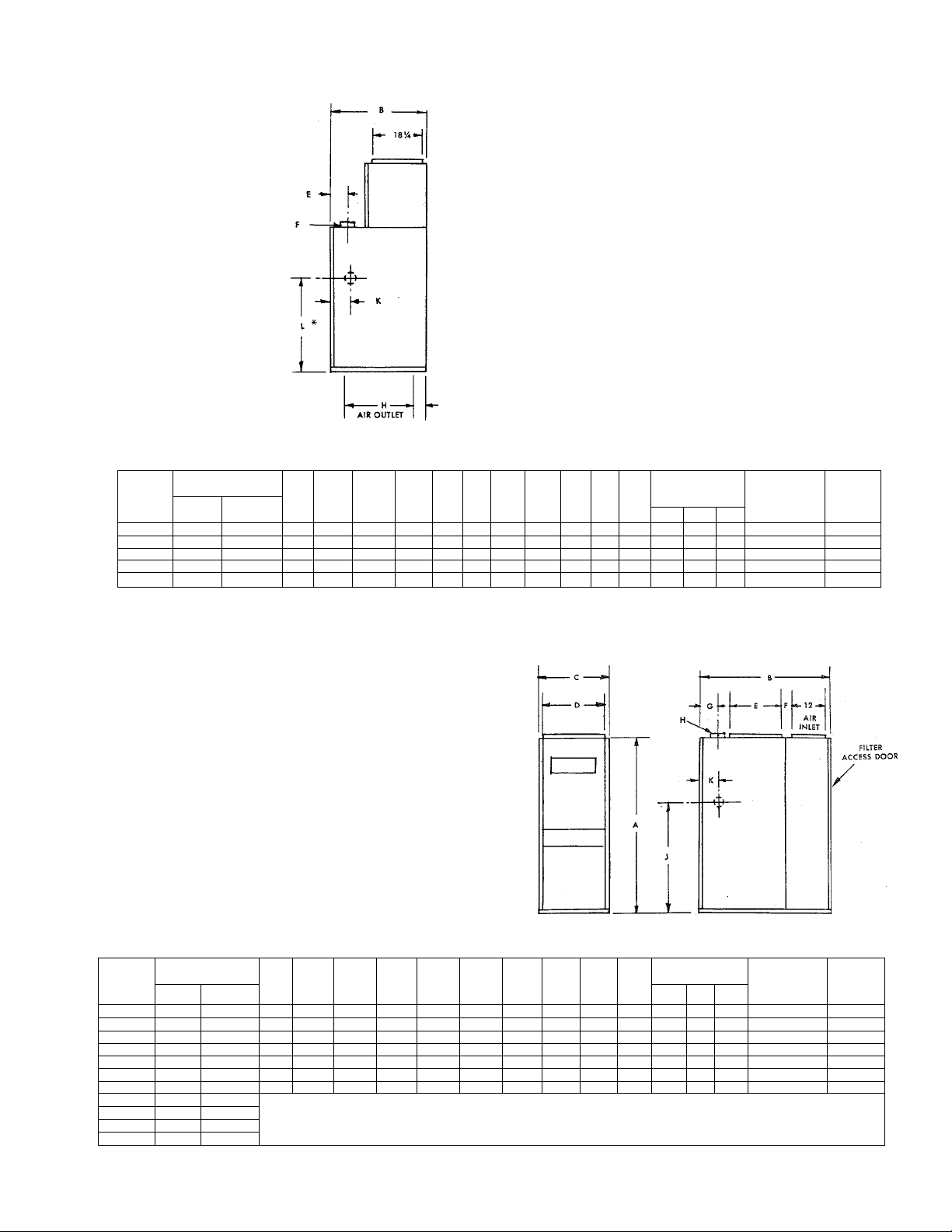
COUNTERFLOW
EZD
G
AIR OUTLET
A.G.A. RATINGS
MODEL
NO.
50-393, ^0,000
**80-393
100-393
125-393 1 25,000 1 00,000 75
150-393 150,000 120,000 80
* Add 1 when installed with base on combustible fioor.
** For LP Gas, Model Designation 80-V-393, A.G.A. Input 75,000, Bonnet Capacity 60,000.
BTU/HR
BONNET
CAPACITY
INPUT
80,000 64,000
100,000
40,000
80,000 75
*
A В C D E F
75
26 16V4
75
26
26
26 20Й 18% 3 5"
283Л
143^
16'Л 14?4
16%
1814
28 26%
2%
2%
3 5"
5Ув 6" 25% 23%
4"
4"
G
22%
12%
12% 22%
14% 22%
18% 22%
FURNACE
*
H
J К
2% 27%
1%
2% 27%
1%
2% 27%
l'/2
2%
1%
4
2Ув
GAS CONNECTION
1
NAT. MFD.
% 'A
Vi
'A
27%
'Л % 'A
30%
% %
SIZES
.'A 'A
'A 'A
Prop.
'A
%
FILTERS
16 X 20 X 1
16 X 20 X 1
Two 10 X 20 X 1
Two 14 X 20 X 1
Two 16 X 20 X 1
APPROX.
SHIPPING
WEIGHT
(LB.)
166
185
210
235
325
BASEMENT
FURNACE
RATINGS
A.G.A.
ВТ
INPUT
200,000
250,000
400,000
U/HR
BONNET
CAPACITY
64,000
80,000 46
100,000 46
120,000
140,000
160,000
200,000
240,000
280,000
320.000
MODEL
NO.
50-393 50,000 40,000
*80-393 80,000
100-393 1 00,000
125-393 1 25,000
150-393 150,000
175-393 175,000
200-393
250-393
300-393 300,000
350-393 350,000
400-393
Ratings ore approved for altitudes to
less for each 1,000 feet above sea
* For LP Gas, Model Designation 80-V-
A В c D
46 40% 16%
.46
40% 16%
40%
40% 20%
51 43% 28% 26% 17%
51 43% 36% 34% 17%
43% 36% 34%
51.
Sizes 250 through 400 are multiples of sizes 125, 150, 1.75, and 200 respectively. Refer to the dimensions
of the smaller sizes to obtain overall dimensions for the larger sizes. Provide clearance dimensions between
units for gas service and casing expansion. Refer to tnstallation instructions for minimum clearances.
2,000 feet for all gases. Ratings for altitudes over 2,000 feet are 4%
level. Return air compartment shipped separately, knocked down.
393, A.G.A. Input 75,000 Bonnet Capacity 60,000.
14%
14У, 20
18% 16У,
18Уа
E F G H J К
20
20
20
173%
23%
23%
3
3
53/s b"
43%
2-5" 30%
43%
2-5" 30%
4" 27%
4" 27%
5"
27% 2%
5"
27% 23%
30% 4
2%
2%
2%
2%
4%
4%
4%
2%
23%
4
4
■ 3 -
GAS CONNECTION
SIZES
NAT. MFD. Prop.
'A 'A
'A 'A
'A 'A 'A
'A
% % %
3%
%
% 'A
%
3% •
'A
'A
3%
•%
FILTERS
14 X 25 X 1 166
14 X 25 X 1
16 X 25 X 1 213
20 X 25 X 1
Two 1 6 X 25 X 1
Two 1 6 X 25 X 1
Two 1 6 X 25 X 1
APPROX.
SHIPPING
WEIGHT
(LB.)
192
238
343
428
428
393U
Page 4

GAS
CONTROL
OPTIONS
Gas and Control Type
Components
City Gas
04 05
Bryant Automatic Pilot
Bryant Gas Control Valve
Gas Pressure Regulator *
Transformer
Pilot Gas Filter **
X
X
X
X X X
X X
100% Shut Off
T. C. Pilot
Pilot Relay
Inline 100% Shut Off Valve
- X -
- -
* On the sizes 50, 80, 100 & 125 for natural gas only,
the regulator is part of a combination regulator, main
gas shut-off and pilot shut-off.
** Mfd. gas only.
LP Gas
02
— —
X
X
X X
X
X
Figure 2 — Thermocouple Pilot
02 & 05 Controls
-
-
nr
4
Figure 4 — Slotted Port Burner
393U
Figure 1 - D2 Controls
641 Valve - 732 Pilot
-4-
Page 5

LOCATING THE UNIT
1. This gas furnace is approved for use on combus
tible floors except when installed as a counter-flow
furnace. When installed as a counter-flow furnace
on a combustible floor it must be installed on an
approved base.
2. The furnace is A.G.A. approved for the following
clearances from combustible construction in a clos
et or alcove installation.
Sides
.......................
0" (!")*
Back........................0" (1")*
t Top of plenum. . . 3" (0")*
Vent connector . . 6" (6")*
Front
.......................
6" (6")*
* Figures shown in parentheses are approved clear
ances when the furnace is installed as a counter
flow furnace.
t Refer to ASA Z21.30-1954 for clearances in open
area installations.
This gas furnace is not approved for use with air
conditioning units mounted upstream from the fur
nace heat exchanger. The cooling coil should either
be downstream of the furnace heat exchanger or the
flow of cooling air should be by-passed around the
heat exchanger. If this parallel arrangement is used,
the dampers or other means used to control the flow
of air must be adequate to prevent chilled air from
entering the furnace. If these dampers are manually
operated, they must be equipped with means to pre
vent operation of either unit unless the damper is
in the full heat or full cool position.
8. In general, when the furnace is installed in a
large open space, there will be enough air for com
bustion and ventilation. However, when the unit is
installed in buildings of unusually air-tight con
struction, or when the furnace is located in very
restricted spaces such as closets or utility rooms,
special provisions must be made for combustion,
ventilating, and draft hood dilution air.
3. Locate the furnace as close to the chimney as
possible. The furnace should also be located as
centrally as possible to the distribution system.
4. Provide ample space for servicing and cleaning.
Consult your local approval agency for any special
clearance requirements.
5. The furnace should be level. Use shims as
required, if the floor or foundation is not completely
level.
6. Advise owner to leave all air passageways to
the furnace free of obstruction in order that there
will be no interference with combustion and venti
lating air.
7. The furnace is designed for use with summer air
conditioning. Therefore consideration should be
given to leaving ample space for a later installation
of air conditioning equipment, if the air conditioning
equipment is not being installed as part of the orig
inal furnace installation.
Bryant manufactures a coil box for upflow furnaces.
If air conditioning will be added at a later date, the
coil box, if installed on the original installation,
will save time and money later. A coil box is not
needed for counter-flow furnaces.
When the unit is installed in a confined space, pro
vide the confined space with two permanent open
ings, one near the top of the enclosure and one near
the bottom. These openings must freely communicate
with interior areas that have adequate infiltration
air from the outside. Each opening must have a free
area of not less than one square inch for each
1000 Btu/hr of rated input of oil appliances located
within the enclosure.
If it is not practicable to connect the two openings
to interior space, or if the interior space has in
sufficient infiltration air, then it is necessary to
connect the openings to the outside. If air openings
are directly to outdoors, the minimum free area
should be one square inch per 3000 Btu/hr of input
rating or in accordance with Z21.30-1964 or latest
edition, “American Standards for Installation of Gas
Appliances and Gas Piping.”
It is strongly recommended that the installer consult
the “American Standards Installation of Gas Ap
pliances and Gas Piping,” ASA Z21.30-1964.
9. In restricted spaces it is very important that the
return air ducts be sealed firmly into the furnace so
that the return air will be kept separate from the
combustion and ventilating air.
- 5 -
393U
Page 6

GAS PIPING
The gas supply line should be a separate line direct
from the meter to the furnace. Check local utility for
recommendations concerning existing lines. Choose
a supply pipe size large enough to keep the pres
sure loss as low as practicable. The supply pipe
should never be smaller than the inlet to the gas
valve. For pipe capacities at 0.3 inches w.c. pres
sure drop, see Iron Pipe Capacity table below.
Observe local codes for all gas pipe installation.
The following are pertinent recommendations:
1. Avoid low spots in long runs of pipe. These low
spots may trap water in the supply line. It is best
to slope all pipe 1/4 inch in 15 feet to prevent
traps. All horizontal runs should slope to risers.
Risers should be used to connect to the furnace and
to the meter.
2. Install a drip leg in the riser leading to the
furnace. This drip leg will serve as a trap for dirt
or condensate.
This drip leg can be installed by connecting a TEE
to the riser leading to the furnace, so that the
straight-through section of the TEE is vertical.
Then connect a capped nipple to this TEE. The
capped nipple should extend below the level of the
gas controls, with the cap resting on the floor.
3. Install the main manual gas shut-off valve in the
supply line five feet above the floor. Install the
valve (supplied) so that the pilot manual cock is on
the inlet side of the valve. (See Figure 5.)
IRON PIPE CAPACITY (See Notes 1 & 2)
Length of Pipe
in Feet
15
30
45
60
75
90
105
120
150 109
180
1. All values shown are based on a pressure drop of 0.3" w.c. and using gas with a specific gravity value
of 0.60 Consult local utility for local variations.
2. To convert to capacities for gas of different specific gravity, multiply the capacity values by the multi
pliers shown at the extreme right on table.
Pipe Capacity in Cubic Feet Per Hour
for Diameters Shown
1/2" 3/4"
76
52
43 99
38 86 173 380
172
120 241 535 .40
77
70 141
65
1"
345
199
155
131
120 270
100
1-1/4" Specific Gravity
750 .35
435 .45
345 .55
310
285
242
225
Figure 6
Multiplier to Use
for Different Specific Gravity
Multiplier
1.31
1.23
1.16
.50
.60
.65 .962
.70
1.10
1.04
1.00
.926
393U
- 6 -
Page 7

Sizes 50, 80,100 8s 125 using natural gas are equip
ped with a factory-installed combination pressure
regulator and main shut off - pilot supply shut off
valve. This control is inside the furnace cabinet.
A separate manual shut-off valve is not supplied
with these furnaces. Consult local codes regarding
the need for placing a separate shut-off valve out
side the furnace cabinet as shown in Figure 5.
Where a gum filter is required by local regulations,
place filter between manual gas cock and pilot
cock. See Figure 6.
Place a ground joint union between the gas control
manifold and the manual gas shut-off valve.
4. Support all piping with appropriate straps, hang
ers, etc. This will maintain proper slope of the lines
as installed and will remove unnecessary strain on
the furnace and its controls. It will also prevent
the piping from being moved accidentally from its
installed position.
5. Joint compounds — (pipe dope) should be applied
sparingly and only to the male threads of the joints.
Consult local supplier for type of compound to be
used with LP gas.
6. After all connections have been made, purge
the lines and check for leakage. Never purge a line
into a combustion chamber. Never use matches,
candles, flame, or other sources of ignition for the
purpose of checking leakage.
3. Run pipe as directly as possible with a minimum
number of turns. The maximum length of horizontal
run should not exceed 75 percent of the height of
the chimney.
4. Maintain a minimum of 1/4 inch per linear foot
upward slope from the furnace to the chimney on all,
horizontal runs.
5. Rigidly support the flue pipe with hangers and
straps to insure that there will be no movement
after installation.
6. Extend the flue connection pipe through the
chimney wall flush with the inner face of the chim
ney liner. Never connect into a chimney serving an
open fireplace, unless the fireplace opening is
sealed off.
7. The chimney or gas vent should extend high
enough above the roof or neighboring obstruction
so that wind from any direction will not create a
positive pressure in the vicinity of the outlet of
the chimney or gas vent. The installer is referred
to Part V of American Standard “Installation of
Gas Appliances and Gas Piping, ASA Z21.30-1964
for detailed information on chimney and gas vent
use. In general the chimney or gas vent should
extend 3 feet higher than the point of emergence
through the roof, and at least 2 feet higher than any
object within a radius of 15 feet.
8. If more than one appliance is vented into the
same chimney, the cross sectional area of the chim
ney must be as large as the largest flue pipe being
connected, plus 50 percent of the cross sectional
areas of the additional flue pipes being connected.
VENTING THE FURNACE
Consult local codes. Unless the local codes direct
otherwise the furnace may be vented to a permanent
chimney, or to a listed Type B or Type C gas vent.
This Bryant gas-fired furnace has a built in draft
diverter. Therefore, it remains only to connect the
furnace vent collar to the chimney or gas vent to be
used. The following recommendations are made:
1. Select a flue connection material that is satis
factory for the installation, and that meets the
requirements of the local codes.
2. The flue connection pipe must be the same size
as the outlet collar on the furnace. No reduction in
this size is permissible in the pipe run.
9. If more than one appliance is manifolded into
the same flue connecting pipe, the cross sectional
area of this manifold pipe must be as large as the
sum of the cross sectional areas of the pipes con
necting into it.
393U
- 7 -
Page 8

BLOWERS
Direct Drive:
Listed below are the color codes for the different
motor speed taps:
High Speed — Black
Medium Speed - Blue
Medium-low Speed — Yellow
Low Speed - Red
Wiring Diagram, Figure 10 shows these furnaces as
wired at the factory. Remove the transformer (two
screws) from the junction box and expose the termi
nal block. Check the fan control lead to see if it is
connected to the motor speed tap that will give the
blower speed needed for the installation. If the fan
control lead is not connected to the proper motor
speed tap, or if you wish to change to another
speed, simply switch the lead to the motor speed
tap that you want connected. The lead is equipped
with a spade connector.
Important:
If there are variations in voltage at the motor,
there will be significant variations in the air de
livery and temperature rise values. If the supplied
voltage is less than 115 volts the blower will run
slower and the temperature rise will be greater. On
the other hand, if the voltage is greater than 115
volts the blower will run faster and the temperature
rise values will be lower. If there is doubt about
the value and fluctuation of voltage consult local
electric utility. The Number 4 tap should be used
on installations where the voltage is 125 volts or
higher.
Larger Motors:
For some installations the installer may wish to
substitute a larger motor than the one supplied the
furnace. A separate mounting hole is provided in
each end plate of the blower cage to be used when
motors larger than 1/3 HP are installed. This is an
extruded hole requiring self-tapping bolts. Figure 7
is a photo of a 1/2 HP motor mounted in place of a
smaller motor. Note that the lower mounting hole is
used. When ordering a 1/2 HP motor for installation
be sure that the frame is a size 56. When ordering
still larger motors, be sure that the frame size is
compatible with space available in the blower com
partment.
When the lower mounting holes are used it will, of
course, be necessary to use a longer belt than the
one supplied with the smaller motors.
Belt Drive:
The motors supplied with the belt drive have an
adjustable motor pulley. The air delivery rate is
controlled by the position of this adjustable motor
pulley. When the pulley is in the fully open position,
the air delivery rate is at a minimum, and conse
quently the temperature rise across the furnace is
at the maximum.
When the pulley is in the fully closed position, the
air delivery rate is maximum and consequently the
temperature rise across the furnace is at a minimum.
In order to change the opening on the pulley simply
loosen the set screw with an Allen wrench. Screw
the pulley clockwise to close, and counter-clockwise
open. Once positioned, tighten the set screw on the
flat of the motor shaft.
393U
Figure 7
- 8 -
Page 9

TABLE [
DIRECT DRIVE BLOWERS - HEATING ONLY
Furnace
Size
50 1/6
80 1/6
100
125
Motor
H.P.
1/5
1/4
No. of
Speed Taps
4
4
4
2
Ext. S. P.
Inches Water
0.12
0.12
0.15
0.20
Temp. Rise
Degrees F.
50-70
75-95
75-95 1 870
75-95
Factory
Setting
3
3
1
t Values shown are for 115 volt power supply
tt Temp rise is 60° F TABLE II
HEATING AND COOLING BLOWERS
Furnace
Size
50 1/6
80 1/6
80 1/3 4
100
100 1/3
125
d n a — does not apply * _ speed tap not recommended for heating § Values shown are for 115 volt power supply
Motor
H.P.
1/6
1/3
No. of
Speed Taps
4
4
4
4
4
80-90
Temp. Rise Degrees F.
Motor Speed Taps
Hi
*
*
* ie
*
*
Med
*
80-90
90-100
70-75
80-90
Med-Lo Lo
60-70
95-105
★
*
75-85
90-100
80-90
*
*
*
*
Ext. S.P.
In. w.c.
0.32
0.30
0.35
0.40
0.30
0.35
0.40
0.50
0.30
0.35
0.40
0.30
0.35
0.40
0.50
0.30
0.35
0.40
0.50
Cooling Air Flow-CFM§
at Motor Speeds Shown
Hi Med
710
810
785
760
1185
1160
1130
1080
830
805
775
1250
1215
1200
1110
1525
1500
1470
1400
85° F Temp. Rise
Med-Lo
610
660
645
625
980
965
940
895
675
655
635
1030
1015
1000
960
1060
1045
1030
1010
tCFM at
tt 615
695
1090
485
510
500
490
865
850
830
815
505
495
490
900
890
870
830
925
910
900
860
Lo
d n a
d n a
d n a
d n a
d n a
d n a
d n a
d n a
d n a
d n a
d n a
d n a
d n a
d n a
d n a
d n a
d n a
d n a
d n a
TABLE III
BELT DRIVE BLOWERS
Heating Heating and Cooling
Furnace
Size
80
100
125
150
175 1/3 5„ T.O. 1475 83° F 1/2 5 T.O.
200
Motor
H.P.
1/6 3 T.O.
1/4
. 1/4 4/2 T.O.
1/3
1/3
Factory
Setting
3 T.O. 730
5 T.O.
5 T.O.
CFM
@ 0.20
570
950
1160
1475 94° F
Temp.
Rise
97° F
95° F
92° F
90° F 1/2 5 T.O. 1160
Motor
H.P.
1/3 4
1/3
1/3
1/2 5 T.O. 1280 68° F
3/4
3/4
1/2
3/4 5
Factory
Setting
4 T.O. 930 75° F
4/2 T.O.
5 T.O. 1600
5 T.O. 1500
5
CFM
@0.20
T.O.
T.O. 1500
T.O. 1500
790
950 92° F 1080 36M
1500
Temp.
Rise
70° F 1080
90° F
65° F 2280 60M
81° F
81° F
93° F 2400 54M
93° F 2400 66M
Max. CFM
@ 0.40
1270
1800
1840
2400 54M
2400 66M
Approx.
A/C Capacity
30M
36M
48M
48M
393U
Page 10

ELECTRICAL CONNECTIONS
START-UP AND ADJUSTMENT
All electrical connections are to be made in accord
ance with the local codes governing such wiring.
A permanent, live, separately fused electric power
supply, complete with manual switch, should be
provided for the furnace.
The room thermostat should be located where it will
be in the natural circulating path of room air. Avoid
locations where the thermostat would be exposed to
cold air infiltration, drafts from windows, doors, or
other openings leading to the outside; or exposure
to air currents from warm or cold air registers; or to
exposure where the natural circulation of the air is
cut off such as behind doors, above or below man
tels, shelves, etc.
The thermostat should not be exposed to heat from
nearby radiators, fireplaces, radios, televisions,
lamps, or rays from the sun. Nor should the thermo
stat be mounted on a wall containing pipes or warm
air ducts, or a flue or vent which could affect its
operation and prevent it from properly controlling
the room temperature. Any hole in the plaster or
panel through which the wires pass from the thermo
stat should be adequately sealed with suitable
material to prevent drafts from affecting the thermo
stat.
INSTALLING THE UNIT
Sizes 50, 80,100 & 125 for natural gas are complete
ly assembled at the factory. All other units are
shipped fully assembled with the exception of the
manual main shut-off valve, pilot feed tube, and
pilot gas filter, which are shipped loose. The filter
is snpplied for manufactured gas units only.
The order to be followed in setting the unit in place
and making all the necessary connections (gas,
electric, venting, duct work, etc.) is left to the
discretion of the installer. Recommendations listed
on pages 5 to 7 of this instruction should be fol
lowed. When making the gas piping installation as
described on page 6, assemble the pilot manual shut
off valve in the threaded boss provided at the inlet
side of the main manual gas shut-off valve. If the
installation is for manufactured gas, install the gum
filter between the two valves. Cut the pilot feed
tube to the desired length and connect the pilot
manual shut-off to the pilot.
Check to be sure that all connections have been
properly made, then proceed as follows:
Light the pilot using the procedure outlined on the
Lighting Instruction Plate attached to the furnace.
However, when lighting the pilot for the first time,
perform the following additional steps:
1. If the supply line was not purged prior to con
necting the furnace, it will be full of air. Since it
would take a long time to vent this air through the
small pilot port, it is recommended that the pilot
supply line be disconnected at the pilot shut-off
valve and the supply line be allowed to purge until
the odor of gas is detected. Never purge gas lines
into the combustion chamber. Immediately upon
detection of gas odor, re-connect the pilot supply
tube. Allow 5 minutes to elapse and light the pilot
in accordance with the instructions on the front of
the furnace.
2. The pilot flame should be soft blue in color.
a. For city gas controls (D4) this flame should be
of sufficient length to provide good impingment on
the mono-metal element of the Bryant pilot. Flame
should extend upward between the carry-over ports
of the two adjacent burners.
b. For LP gas controls (D2), the flame should
surround the tip of the thermocouple element of the
pilot and extend downward to include 3/8 inch to
1/2 inch of the thermocouple. The flame must never
come in contact with any other part of the thermo
couple or its lead wire. The flame lies under the
carry-over ports of the burners and merges with the
carry-over flames. D5 controls have the same pilot.
3. If the pilot flame does not have the appearance
described above, it may be adjusted by means of the
manual pilot shut-off valve.
a. If the valve is equipped with an adjustable
screw, turn the handle to the full-open position and
remove the screw cap on the valve handle, thus
exposing the adjustable screw. Turn adjusting screw
until flame has the desir-ed appearance. Replace
screw cap.
b. If the valve is not equipped with the adjusting
screw, adjustment of the flame is effected by alter
ing the position of the valve handle.
For furnaces with D2 or D5 controls the pilot feed
tube is connected to the pilot relay.
393U
- 10 -
Page 11

Light Main Burners using the procedure contained on
the metal Lighting Instruction Plate attached to the
front of the furnace.
Adjust Gas Rate. Set the room thermostat on call
for heat and adjust the gas rate as follows:
1. City Gases - Measure gas input at the meter.
The burners are equipped with fixed orifices, sized
to produce the rated input shown on the rating plate.
If measured and rated input are not approximately
the same, the gas pressure regulator may be adjusted
as follows:
a. To increase input: Turn pas pressure regu
lator adjusting screw ‘clockwise’. (Adjusting screw
is concealed under the regulator sealing cap).
b. To decrease input: Turn the adjusting screw
‘counter-clockwise’. The manifold pressure should
be set as follows:
Manufactured Gas - 3 inches w.c.
Natural Gas - 3 inches w.c.
Maximum pressure departure from recommended pres
sure should be plus or minus 0.3 inches w.c.
2. LP Gas - LP gas units are not equipped with
gas pressure regulators. Burner orifices are sized
to give the rated input at a manifold pressure of
11 inches w.c. Since meters are not normally used
with LP gas, it will be necessary in most cases to
check the manifold pressure and adjust the regulator
at the supply tank to provide a pressure of 11 inches
w.c.
3. If the input in item (1) or (2) above is too great
or too little, install new orifices or re-drill the
existing orifices (whichever is necessary) to obtain
the rated input. Be sure the rated input is obtained
without any appreciable change in manifold gas
pressure.
Adjust Main Burner Flame — The main burner flame
should be clear blue, almost transparent, with a welldefined inner cone. If there is insufficient primary
air, the flame will be yellow-tipped. If there is too
much primary air the flame will be well-defined, but
with a tendency to dance or lift off the burner ports.
CHECK CONTROLS
Bryant Diaphragm Gas Control Valve —if not already
checked when lighting the main burner, check the
proper operation of this valve by moving the room
thermostat pointer above and below room temperature
and observe that the main burners light on call for
heat and go off when the pointer is moved below the
room temperature setting. However, there will be
approximately a 30 second delay on ignition and
extinction.
Automatic Pilot - To check the pilot operation
follow the instructions below:
1. Set the room thermostat on call for heat.
There is a delay before burners light.
2. After burners have lit, shut off the pilot gas
valve.
3. The automatic pilot will break the electrical
circuit to the gas valve and the burners will shut off.
Limit Control - This control functions to shut off
the gas if the furnace becomes over-heated. The
method of checking satisfactory operation is left to
the discretion of the installer. Extreme caution
should always be employed.
Blower Adjustment - It is important that the blower
speed be adjusted before there is any attempt to
adjust the fan control switch.
The blower speed is set at the factory. Under no
circumstances should the temperature rise across
the furnace be allowed to exceed 105 degrees F
on all sizes except the size 50. On the size 50,
the temperature rise must not be allowed to exceed
70 degrees F. After the desired air flow or tempera
ture rise across the furnace has been obtained, the
installation should be complete. However, it may be
necessary to change the factory setting on the Fan
Control Switch. This may be done as described
under the discussion on controls.
1. Allow furnace to operate 15 minutes.
2. Adjust each burner by closing the air shutter
until a slight yellow tip appears on the flame; then
open the air shutter just enough to clear the yellow
from the flame.
- n -
393U
Page 12

CLEANING THE FURNACE
L Disconnect gas tubing from pilot.
2. Disconnect electrical lead from pilot. (In case
of 100% shut-off controls disconnect pilot thermo
couple lead from pilot relay).
3. Remove front plate from draft diverter (4 sheet
metal screws.)
4. Remove burners and pilot as follows.
a. Remove tinnerman clamp from burner holding
stud.
b. Lift burner off holding stud, twist and pull
forward.
c. Pilot is attached to one burner and is removed
with that burner. It is not necessary to detach pilot
before removing burner. See Figure 3 for photograph
of burner; also pilot attached.
5. Remove metal angle strip holding flue baffles in
place. See Figure 8.
6. Remove flue baffles. See Figure 9.
7. Use a flexible-handled steel cleaning brush to
loosen scale and soot. Remove these scrapings from
bottom of combustion chamber.
8. Re-assemble furnace by reversing the above pro
cedure. Note: There is a slot in the back of the
heat exchanger for the back tip of the burner to fit
into. When properly placed, the burner will fit into
this slot and will be level.
CARE AND MAINTENANCE
Care of Blowers. All motors on the belt drive blow
ers are provided with oil cups and should be oiled
at least twice a year with a good grade of SAE 30
oil. The motors on the direct drive blowers are
sealed units and do not require the addition of oil.
Blower bearings are semi-permanently lubricated.
This lubrication is normally good for 3 to 5 years.
When necessary to add lubricant, use Plastic E,
obtainable from Bryant’s Service Parts Department.
Filters. Filters should be examined frequently for
clogging due to dirt. The disposable filters should
be replaced when they become dirty. Permanent type
of filters may be cleaned using clear water. Be sure
to coat the filter with water soluble oil after clean
ing.
Cleaning. The heat exchanger should be examined
periodically to see if there has been an accumula
tion of rust, soot, etc. Clean as required.
Figure 8 — Note metal angle strip held by 3 screws
393Ü
Figure 9 — Remove baffles
- 12 -
Page 13

Figure 10 — Wiring for 4-Speed Direct Drive
Figure 11 — Wiring for 4-Speed Direct Drive Using Relay
- 13-
393U
Page 14

393U
Figure 13 - Belt Drive Wiring
- 14-
Page 15

<n
c
<
o
3
-+
3*
CQ
Q
3
(£2
O
3
o
3
TOP VIEW
ITEM DESCRIPTION
7” DIA MANIFOLD
5" PIPE
7” PIPE
10” X 7” REDUCING CAP
10” TEE
10” PIPE
7” ELBOW /
FRONT VIEW
NOTE:USE THIS
ARRANGEMENT
FOR HIGH CEILING
INSTALLATIONS.
Sizes 350 iV. 400
CO
VO
CO
c
c
•5’
c
3
SIZE
2.50
ELBOW
A
5”
6”
REDUCING CAP
B
8" X S’8” X 6”
TEE
C
8”
PIPE (fccomm)
D
5” dia X 6” Ig
6” dia X 6” Ig
•“SPACF. SIZF 250 (TWO 125’&)
4” APART TO PROVIDE SPACE
FOR GAS PIPING.
►—SPACE 300 (TWO ISO’s)
1” APART TO PERMIT EXPANSION
AND CONTRACTION
PIPE
PIPE
F
8” 10”
S"
MI N MIN
G
11” 0“
II
8”
E
5”
6“
 Loading...