

355BAV Preferredt Plus 95i
95% AFUE Upflow Only Variable--Speed
Condensing Gas Furnace
Series C, Input Rates 60,000 thru 120,000 Btuh
Product Data
A05085
FEATURES
Perfect Heatt/Perfect Humidityt Control—This intelligent
heating control constantly monitors operating conditions to adjust
for greater efficiency and comfort. The control operates 90% of
the time in low--heat and reserves the high--firing rate for times
when the heating demand is high. The Perfect Heat/Perfect
Humidity control has these additional features:
S dedicated terminals for electrical connection of electronic air
cleaner and humidifier
S adjustable blower off time
S LED fault code display to aid in servicing
S selectable airflow to match cooling unit
S emergency heat setting
S setting to increase airflow for bypass--type humidifier
S selectable constant fan airflow
S a multi--zone setting for use with zoned air distribution
systems a special dehumidification function increases cooling
comfort by providing greater humidity removal in summer
months
S controls humidity even when there is no heating or cooling
demand
Three--Pass Primary Heat Exchangers—This design
accelerates heat transfer and extracts heat that conventional heat
exchangers waste up the flue. The primary heat exchanger is
made of aluminized steel for corrosion resistance.
Building on our industry--leading condensing furnace
technology, the model 355BAV is our greatest innovation in
comfort control and operating efficiency.
Modern technology provides the Plus 95it design with great
reliability, high efficiency, and ultra--quiet operation. Efficiencies
are above 95 percent Annual Fuel Utilization Efficiency (AFUE).
The model 355BAV Plus 95it Condensing Gas Furnace
incorporates our patented Perfect Heatt Control. This control
interacts with a 2--stage gas valve, a variable--speed inducer
motor, and a variable--speed blower motor, allowing the Plus
95it to adjust combustion air, firing rate, and airflow to maintain
peak efficiency throughout the operating cycle.
The Perfect Heatt system provides the ultimate in heating
comfort while minimizing electrical and gas consumption. The
Plus 95i also features Perfect Humidity control when combined
with a Bryant Thermidistatt Control and air conditioner or heat
pump system.
For even greater comfort and convenience, match the Plus 95i
furnace with a two--speed heat pump to create a HYBRID
HEAT® Dual Fuel system.
Flow--Through Secondary Heat Exchangers—Each cell is
laminated with our patented Everlastict polypropylene for
greater resistance to corrosion and is epoxy coated externally to
prevent oxidation. This breakthrough in heating technology
(Patent No. 4,738,307) helps extend the life of the furnace for
years of reliable performance. The heat exchangers are positioned
in the furnace to extract additional heat from the combustion
products regardless of furnace orientation.
Perfect Lightt Igniter—Bryant’s unique SiN igniter is not only
physically robust but it is also electrically robust. It is capable of
running at line voltage and does not require complex voltage
regulators as do other brands. This unique feature further
enhances the reliability of Bryant’s 355BAV gas furnace and
continues Bryant’s tradition of technology leadership and
innovation in providing a reliable and durable product.
FanOnPlust—Improves comfort all year long by allowing
you to select the continuous fan speed right at the thermostat.
SmartEvapt—Allows your system to reduce summertime
humidity levels by nearly 10% over standard systems.
1
Upflow Only Design—Allows the model 355BAV to be installed
in an upflow orientation only. Factory configured for upflow
applications. The model 355BAV is available in 5 heat/airflow
combinations.
Direct Venting—This furnace can be installed as a 2--pipe/Direct
vent furnace.
2--Stage Gas Valve—The 355BAV has a 2--stage gas valve to
vary the amount of gas being used from low--heat to high--heat
stage.
Fully--Insulated Casing—Foil--faced insulation in the heat
exchanger section cuts the heat loss; double--density insulation in
the blower section reduces noise levels. The casing also has the
required openings for left-- or right--side connection of gas,
electric, drain, and vent connections.
Variable--Speed Motors—Variable--speed operation improves
the comfort levels in the home. Variable--Speed motors are also
355BAV
more economical to operate than standard motors. They have the
ability to adapt to changing conditions and provide consistent,
comfortable, and quiet heating. Motors and electronic controls are
covered by a 5--year limited warranty.
Sealed Combustion System—This furnace brings in combustion
air from outside the furnace, which results in especially quiet
operation.
Monoport Inshot Burners—Produce precise air--to--gas mixture
for clean burning. The large monoport on the inshot or injection
type burners seldom, if ever, needs cleaning.
Quality Registration—The 355BAV is engineered and
manufactured under an ISO 9001 registered quality system.
Certifications—The 355BAV units are CSA (A.G.A. and
C.G.A.) design certified for use with natural and propane gases,
as well as AHRI efficiency rating certified. The furnace is factory
shipped for use with natural gas. An CSA (A.G.A. and C.G.A.)
certified gas conversion kit is required to convert furnace for use
with propane gas. The model 355BAV meets California Air
Quality Management District emission requirements.
I
G
S
E
N
D
Always Ask For
Use of the AHRI Certified TM Mark indicates a
C
E
R
D
E
I
T
F
I
CERTIFIED
manufacturer’s participation in the program. For
verification of certification for individual products,
go to www.ahridirectory.org.
2
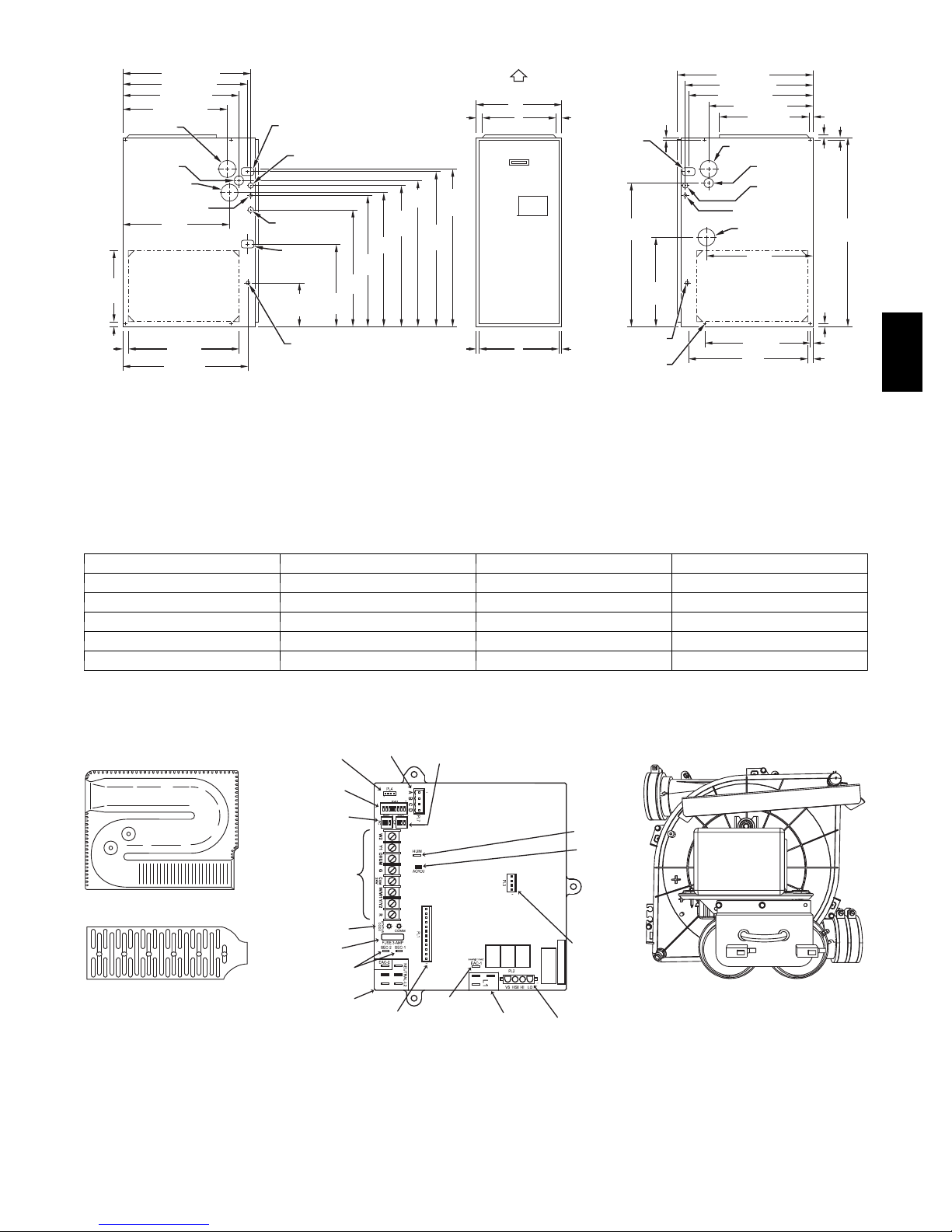
DIMENSIONS
X
(
15
(684 mm)
26
⁄
16
"
(667 mm)
26 1 ⁄4 "
1
(622 mm)
24
⁄2 "
5
(567 mm)
⁄
16
"
22
2-IN . (51 mm) COMBUSTIONAIR CONN
1
⁄2 -IN . (13mm) DI A
GAS CONN
2-IN (51mm)
.
VENT CONN
1
⁄2 -IN . DIA (13mm)
THERMOST AT ENT RY
11
22
⁄
16
"
(576 mm)
SIDE INLE T
(591 mm)
23 1 ⁄4 " TYP
SIDE INLE T
15
26
⁄
16
" TYP
(684 mm)
1 1 ⁄4 "
14 1 ⁄2 "
TYP
(368 mm)
(32 mm)
1 "
(25mm)
AIRFL OW
13
/
16
"
CONDENSA TE DRAI N
TRAP LOCA TION
(DO WNFLO W &
HORIZONT AL LEF T )
7
⁄8 -IN . DI A (22mm)
PO WER CONN
11
7
⁄8 -IN . DI A (22mm)
A CCESSOR Y
PO WER ENT RY
CONDENSA TE
DRAIN TRAP
LOCA TION
(AL TERNA TE
UPFL OW )
(240 mm)
9 7 ⁄
16
"
17 5 ⁄
TYP
(439 mm)
CONDENSA TE
DRAIN LOCA TIO N
(UPFLO W)
(622 mm)
16
NO TES: 1. Minimum retur n-air openings at fur nace , based on metal duct. If fle x duct is used,
2. Minimum retur n-air opening at fur nace:
29
TYP
(754 mm)
5
⁄8 "
27
(702 mm)
9
⁄
16
"
27
TYP
(700 mm)
1
24
⁄2 "
"
see fle x duct manuf acturerí s recommendations f or equiv alent diameters .
a. F or 800 CFM–16-in. (406mm) round or 14 1 /
b. F or 1200 CFM–20-in. (508mm) round or 14
c. F or 1600 CFM–22-in. (559mm) round or 14 1 /
d. F or airflo w requirements abo v e 1800 CFM, see Air Deliv er y tab le in Product Data
literature f or specific use of single side inlets . The use of both side inlets , a
combination of 1 side and the bottom, or the bottom only will ensure adequate
retur n air openings f or airflo w requirements abo v e 1800 CFM .
(21 mm)
1
13
⁄4 "
33
30
⁄
16
"
TYP
(783 mm)
(845 mm)
⁄
16
"
5
32
⁄8 "
TYP
(829 mm)
11
/
16
"
(17 mm) (17 mm)
A
D
OUTLET
INLE T
E
2 (368 mm)x 12-in. (305 mm) rectangle .
1
/
2 (368mm)x 19
2 (368mm)x 23
13
/
16
"
(21 mm)
CONDENSA TE DRAI N
TRAP LOCA TION
(DO WNFL OW &
HORIZONT AL RIGHT)
OR AL TERNA TE
1
⁄2 -IN . DIA GAS CONN
DRAIN LOCA TION
11
/
16
"
DIMPLE LOCA T ORS
FOR HORIZONT AL
1
/
2 -in. (495mm) rectangle .
1
/
4 -in. (591mm) rectangle .
(14 mm)
30 1 ⁄2 "
(775 mm)
18 1 ⁄4 "
(464 mm)
CONDENSA TE
(UPFL OW )
HANGING
9
TYP
1
(724 mm)
⁄2 "
28
15
(684 mm)
26
⁄
16
"
(667 mm)
26 1 ⁄4 "
5
(567 mm)
22
⁄
16
⁄
16
"
"
19 "
(483 mm)
OUTLET
2-IN . (51mm)
COMBUSTION-AIR CONN
1
⁄2 -IN . DI A (13mm)
GAS CONN
7
⁄8 -IN . DI A (22mm)
PO WER CONN
1
⁄2 -IN . DI A (13 mm)
THERMOS TA T ENTR Y
2-IN . (51 mm)
VENT CONN
11
22
⁄
16
"
(576 mm)
13
⁄
16
5
⁄8 "
(16 mm)
(21 mm)
"
(16 mm)
5
⁄
16
"
7
⁄8 "
39
(1013 mm)
SIDE INLE T
(25 mm)
1 "
7
(11 mm)
⁄
16
22 1 ⁄4 " TYP
(565 mm)
24 3 ⁄
16
"
BO TT OM INLE T
(614 mm)
"
11
(25 mm)
⁄
16
"
355BAV
A05124
Dimensions -- In. (mm)
UNIT SIZE A D E
060 --- 14 / 042060 17--- 1/2 / 445 15--- 7/8 / 403 16 / 406
080 --- 14 / 042080 21 / 533 19--- 3/8 / 492 19--- 1/2 / 495
080 --- 20 / 060080 21 / 533 19--- 3/8 / 492 19--- 1/2 / 495
100 --- 20 / 060100 21 / 533 19--- 3/8 / 492 19--- 1/2 / 495
120 --- 20 / 060120 24--- 1/2 / 622 22--- 7/8 / 581 23 / 584
CONTINUOUS FAN
FACTORY TEST
Heat Exchangers
A92505
MODEL PLUG
CONNECTOR
SW1 SETUP
SWITCHES AND
BLOWER OFF-
DELAY
AIR CONDITIONING
(A/C) AIRFLOW
SETUP SWITCHES
24-V THERMOSTAT
TERMINALS
STATUS AND COMM
LED LIGHTS
3-AMP FUSE
TRANSFORMER 24-VAC
CONNECTIONS
115-VAC (L2) NEUTRAL
CONNECTIONS
CONNECTOR
PL1 LOW VOLTAGE MAIN
HARNESS CONNECTOR
(CF) AIRFLOW
SETUP SWITCHES
EAC-1 TERMINAL
115-VAC 1.0 AMP MAX.)
Control Center
115-VAC (L1) LINE
VOLTAGE CONNECTIONS
A09679
HUMIDIFIER
TERMINAL (24-VAC
0.5 AMP MAX.
ACRDJ AIR
CONDITIONING
RELAY DISABLE
JUMPER
PL3 ECM BLOWER
HARNESS
CONNECTOR
DATE CODE XXXXN
PL2 HOT SURFACE
IGNITER & INDUCER
MOTOR CONNECTOR
Inducer Assembly
A02286
A06450
3
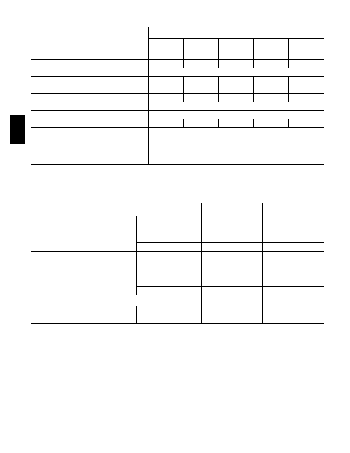
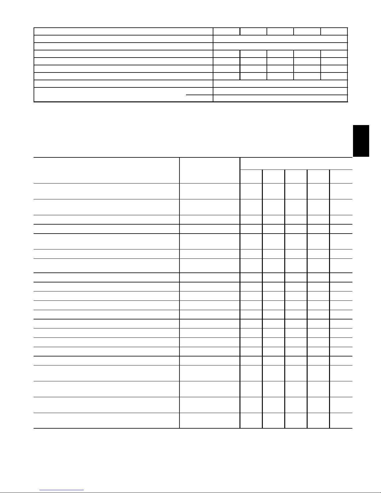
PHYSICAL DATA
UNIT SIZE
DESCRIPTION
042060 042080 060080 060100 060120
Direct---Drive Motor Hp (ECM) 1/2 1/2 1 1 1
Motor Full Load Amps 7.7 7.7 12.8 12.8 12.8
RPM (Nominal)—Speeds Variable 250 — 1300
Blower Wheel Diameter X Width (in.) 10 X 7 11 X 10 11 X 10 11 X 10 11 X 10
Filter Size (in.) Nominal A (Washable) (1) 16 X 25 X 1 (1) 20 X 25 X 1 (1) 20 X 25 X 1 (1) 20 X 25 X 1 (1) 24 X 25 X 1
Shipping Weight (lb) 170 182 204 203 234
Limit Control SPST
Heating Blower Control (Off Delay) Selectable 90, 120, 150, or 180 SEC Intervals
Burners (Monoport) 3 4 4 5 6
Gas Connection Size 1 / 2 --- in . N P T
355BAV
Gas Valve (Redundant) Manufacturer
Minimum Inlet Pressure (in. wc)
Maximum Inlet Pressure (in. wc)
Ignition Device H o t S u r f a c e --- S i N
W h i t e --- R o d g e rs
4.5 (Natural Gas)
13.6 (Natural Gas)
PERFORMANCE DATA
UNIT SIZE
DESCRIPTION
042060 042080 060080 060100 060120
Certified Temp Rise Range (_F)
Certified Ext Static Pressure (ESP) (in. wc)
Airflow CFM*
Output Capacity Btuh} (ICS)
AFUE%}
Input Btuh**
* Airflow shown is for bottom only return --- air supply with factory---supplied 1---in. washable filter(s). For air delivery above 1800 CFM, see Air Delivery table for
other options.
{ Low heat CFM when low - --heat rise adjustment switch (SW1---3) on furnace control is used.
} AFUE and capacity in accordance with U.S. Government DOE test procedures.
** Gas input ratings are certified for elevations to 2000 ft. For elevations above 2000 ft, reduce ratings 2% fo r each 1000 ft above sea level. In Canada, derate
the unit 5% for eleva tions from 2000 to 4500 ft above sea level.
Low 40—70 40—70 40—70 40—70 40—70
High 35—65 40—70 35—65 45—75 45—75
Heating 0.12 0.15 0.15 0.20 0.20
Cooling 0.50 0.50 0.50 0.50 0.50
Heating Low 635 (700{) 860 (945{) 880 (970{) 1105 (1215{) 1325 (1455{)
Heating High 1070 1245 1490 1525 1900
Cooling (Max) 1400 1372 1975 1950 2060
Low 37,000 50,000 50,000 63,000 75,000
High 56,000 75,000 75,000 94,000 113,000
95.0 95.0 95.0 95.0 95.0
Low 39,000 52,000 52,000 65,000 78,000
High 60,000 80,000 80,000 100,000 120,000
4
ELECTRICAL DATA
UNIT SIZE 042060 042080 060080 060100 060120
U n it V ol t s --- He r tz --- P ha s e 1 1 5 --- 60 --- 1
Operating Voltage Range (Min--- Max)* 104--- 127
Maximum Unit Amps 8.9 8.9 13.8 13.8 13.8
Minimum Wire Size 14 14 12 12 12
Maxium Wire Length (ft){ 31 31 32 32 32
Maximum Fuse or Ckt Brk (Amps)} 15 15 20 20 20
Transformer (24v) 40va
External Control Power Available Heating 25va
Cooling 34va
* Permissible limits of the voltage range at which the unit will operate satisfactorily.
{ Length shown is as measured 1 way along wire path between unit and service panel for maximum 2% voltage drop.
} Time---delay type is recommended.
BRYANT ACCESSORIES
UNIT SIZE
DESCRIPTION PA R T NO.
042060 042080 060080 060100 060120
Vent T ermination Kit (Bracket Only for 2 Pipes)
Concentric Termination Kit (Single Exit)
Condensate Freeze Protection Kit KGAHT0101CFP X X X X X
Germicidal Air Purifier Model GAPA X X X X X
Condensate Neutralizer Kit (obtained thru RCD)
Electronic Air Cleaner Model EACA X X X X X
Mechanical Air Cleaner
Humidifier Model HUM X X X X X
Heat Recovery Ventilator Model HRV X X X X X
Energy Recovery Ventilator Model ERV X X X X X
UV Lights Model UVL X X X X X
E Z F le x M ed i a F i lt e r w it h e nd c a p s --- 1 6 --- i n . ( 9 p a c k) EXPXXLMC0016 X
E Z F le x M ed i a F i lt e r w it h e nd c a p s --- 2 0 --- i n . ( 9 p a c k) EXPXXLMC0020 X X X
E Z F le x M ed i a F i lt e r w it h e nd c a p s --- 2 4 --- i n . ( 6 p a c k) EXPXXLMC0024 X
R e p l ac e me n t E Z F l ex F i lt e r --- 16 --- i n . ( 10 p a c k) EXPXXFIL0016 X
R e p l ac e me n t E Z F l ex F i lt e r --- 20 --- i n . ( 10 p a c k) EXPXXFIL0020 X X X
R e p l ac e me n t E Z F l ex F i lt e r --- 24 --- i n . ( 10 p a c k) EXPXXFIL0024 X
E x te ri o r F i lt e r R ac k --- U ni v e r sa l , 1 --- i n . ( ad j u s ta b l e f r o m 1 4 --- i n. t o
2 4 --- i n. ) w it h f il t er
Unframed Filter 1--- in. — 16 x 25
Unframed Filter 1--- in. — 20 x 25
Unframed Filter 1--- in. — 24 x 25
2--- in. — KGAVT0101BRA
3--- in. — KGAVT0201BRA
2--- in. — KGAVT0701CVT
3--- in. — KGAVT0801CVT
P908--- 0001
Model FILCAB or
EZXCAB
KGAFR0301ALL
KGAFR0306ALL (6 pack)
KGAWF1301UFR
KGAWF1306UFR (6 pack)
KGAWF1401UFR
KGAWF1406UFR (6 pack)
KGAWF1501UFR
KGAWF1506UFR (6 pack)
X X X X X
X X X X X
X X X X X
X X X X X
X X X X
X S S S
X X X
355BAV
X
5

BRYANT ACCESSORIES (CONTINUED)
UNIT SIZE
DESCRIPTION PA R T NO.
042060 042080 060080 060100 060120
N a t u ra l --- To --- P r op an e G as C o n ve r s i o n K it ( S i n g l e K i t ) * KGANP4601ALL X X X X X
P r o p an e --- To --- N at u ra l G as C o n ve r s i o n K it ( S i n g l e K i t ) KGAPN3901ALL X X X X X
ECM Motor Simulator (simulates the ECM blower and inducer
motor to aid troubleshooting)
Door Gasket Kit KGBAC0110DGK X X X X X
Advanced Product Monitor (software and hardware to link pc
laptop to control board)
ECM Control Replacement Module --- 1/2 HP HK44EA123 X X
ECM Control Replacement Module --- 1 HP HK52EA123 X X X
Gas Orifice Kit Size 42 (Qty 50) KGAHA0150N42
Gas Orifice Kit Size 43 (Qty 50) KGAHA0250N43
355BAV
Gas Orifice Kit Size 44 (Qty 50) KGAHA0350N44
Gas Orifice Kit Size 45 (Qty 50) KGAHA0450N45
Gas Orifice Kit Size 46 (Qty 50) KGAHA0550N46
Gas Orifice Kit Size 47 (Qty 50) KGAHA1550N47
Gas Orifice Kit Size 48 (Qty 50) KGAHA850N48
Gas Orifice Kit Size 54 (Qty 50)
Gas Orifice Kit Size 55 (Qty 50)
Gas Orifice Kit Size 56 (Qty 50)
Gas Orifice Kit Size 1.25mm (Qty 50)
Gas Orifice Kit Size 1.30mm (Qty 50)
* Factor y ---author ized an d field---installed. Gas conversion kits are C SA (AGA/CGA) recognized.
S --- 16 x 25 filters suitabl e for side return on al l furnace sizes.
KGASD0301FMS X X X X X
KGAFP0301APM X X X X X
See Installation Instructions for model, altitude,
and heat value usages.
KGAHA0850P54
KGAHA0750P55
KGAHA0850P56
KGAHA05750125
KGAHA5750130
6

THERMOSTAT AND ZONING CONTROL OPTIONS
NON---PROGRAMMABLE THERMOSTAT SELECTION
T 6 --- N A C o r T 2 --- N A C
T 6 --- N H C o r T 2 --- N H C
T 2 --- N R H *
* Model HP & 2 Stage thermostat must be field converted to air conditioner operation.
PROGRAMMABLE THERMOSTAT SELECTION
T 2 --- P A C
For use with 1 speed Air Conditioner --- _F/_C, Auto Changeover
For use with 1 speed Air Conditioner --- _F/_C, Auto Changeover
For use with 2 speed Air Conditioner --- _F/_C, Auto Changeover
For use with 1 speed Air Conditioner --- _F/_C, Auto Changeover, 7 --- Day
Programmable
T2--- PHP*
T 2 --- P RH *
T 2 --- P A C
T 2 --- P RH {
T 2 --- P RH }
* Model HP & 2 Stage thermostat must be field converted to air conditioner operation.
{ Hybrid Heat Dual Fuel system thermostat is used with furnace and heat pump application.
} Thermidistat can be con figured multipl e use and staging. It must be con figured for each specific application.
For use with 1 speed Heat Pump --- _F/_C, Auto Changeover, 7--- Day
Programmable
For use with 2 speed Air Conditioner --- _F/_C, Auto Changeover, 7 --- Day
Programmable
For use with 1 speed Air Conditioner --- _F/_C, Auto Changeover, 5 --- 2
Programmable
F o r u s e w it h t wo --- s t ag e a p p li c at i on s --- _F/_C, Auto Changeover, 7--- Day
Programmable
F o r m u lt i --- u se / s t a g e c on f i gu ra t io n s --- _F/_C, Auto Changeover 7--- Day
Programmable
ZONING CONTROL SELECTION
ZONEBB3Z(AC/HP)01
ZONEBB2KIT01--- B
ZONEBB4KIT01--- B
ZONEBB8KIT01--- B
Comfort Series Three---Zone Zone Kit
2--- Performance Series Zoning/Temperature and Humidity Control
4--- Performance Series Zoning/Temperature and Humidity Control
8--- Performance Series Zoning/Temperature and Humidity Control
355BAV
7

AIR DELIVERY -- CFM (BOTTOM RETURN WITH FILTER)*
Unit Size Operating Mode
042060
†† Low Heat 635† 0 ---0.50 635 635 625 615 615
†† 1 --- 1 / 2 --- To n A /C C oo li n g 525 0---0.50‡ 525 525 510 495 465
†† 2 --- To n A / C C oo l in g 700 0 ---0.50‡ 700 700 695 680 680
042080***
†† Low Heat 900† 0 ---0.50 860 870 880 885 885 880 870 855 850 845
†† 1 --- 1 / 2 --- To n A /C C oo li n g 525 0---0.50‡ 515 495 490 475 465
†† 2 --- To n A / C C oo l in g 700 0 ---0.50‡ 685 680 670 665 665
060080***
355BAV
†† Low Heat 880† 0 ---0.50 880 880 880 875 880
†† 2 --- To n A / C C oo l in g 700 0 ---0.50‡ 670 640 635 630 630
†† 2 --- 1 / 2 --- To n A /C C oo li n g 875 0---0.50‡ 870 875 865 865 865
060100***
†† Low Heat 1110† 0 ---0.50 1105 1110 1110 1110 1110 1110 1110 1110 1110 1110
†† 2 --- To n A / C C oo l in g 700 0 ---0.50‡ 700 690 690 690 690
†† 2 --- 1 / 2 --- To n A /C C oo li n g 875 0---0.50‡ 835 845 855 860 865
060120
†† 2 --- To n A / C C oo l in g 700 0 ---0.50‡ 700 700 700 700 695
†† 2 --- 1 / 2 --- To n A /C C oo li n g 875 0---0.50‡ 870 875 875 865 870
* Actual external static pressure (ESP) can be determined by using the fan laws (CFM2proportional to ESP); such as, a system with 1750 CFM at 0.5 ESP
would operate at high ---heating airflow of 1500 CFM at 0.37 ESP and low ---heating airflow of 880 CFM at 0.13 ESP.
{ All heating CFMs are when low--- heat rise adjustment switch (SW1---3) and comfort/efficiency adjustment switch (SW1 --- 4) are OFF.
} Ductwork must be sized for high --- heating CFM within the operational range of ESP.
** Wattage data provided is for the circulating blower with bottom return and does not include draft inducer, accessories, or gas controls.
{{ Operation within the blank areas of the chart is not recommended because high--- heat operation will be above 1.0 ESP.
*** All airflows on 21 in. casing size furnaces are 5% less on side return only installations.
High Heat 1070† 0 --- 1 .0 1070 1070 1070 1070 1070 1070 1070 1070 1065 1045
2 --- 1 / 2 --- To n A /C C oo li n g 875 0---1.0‡ 850 870 875 875 870 860 845 825 810 805
3 --- To n A / C C o ol in g 1050 0 --- 1 . 0 1050 1050 1050 1050 1050 1050 1050 1050 1050 1045
3 --- 1 / 2 --- To n A /C C oo li n g 1225 0 --- 1 .0 1225 1225 1225 1225 1225 1225 1225 1225 1225 1205
Maximum 1400 0 --- 1. 0 1400 1400 1400 1400 1400 1400 1400 1400 1380 1325
High Heat 1245† 0 --- 1 .0 1245 1245 1245 1245 1245 1245 1245 1235 1190 1145
2 --- 1 / 2 --- To n A /C C oo li n g 875 0---1.0‡ 830 840 850 860 860 855 840 830 825 820
3 --- To n A / C C o ol in g 1050 0 ---1.0‡ 1050 1050 1050 1050 1050 1045 1040 1025 1015 1000
3 --- 1 / 2 --- To n A /C C oo li n g 1225 0 --- 1.0‡ 1225 1225 1225 1225 1225 1225 1225 1225 1185 1140
Maximum 1400 0 ---1.0‡ 1400 1400 1400 1400 1375 1325 1280 1235 1190 1145
High Heat 1500† 0 --- 1 .0 1485 1495 1500 1500 1500 1500 1500 1485 1475 1465
3 --- To n A / C C o ol in g 1050 0 ---1.0‡ 1050 1045 1040 1045 1045 1050 1050 1050 1045 1040
3 --- 1 / 2 --- To n A /C C oo li n g 1225 0 --- 1.0‡ 1225 1225 1225 1225 1225 1225 1225 1225 1225 1225
4 --- To n A / C C o ol in g 1400 0 ---1.0‡ 1330 1345 1360 1375 1380 1380 1380 1370 1365 1355
5 --- To n A / C C o ol in g 1750 0 --- 1 . 0 1750 1750 1750 1750 1750 1750 1745 1725 1700 1685
Maximum 2000 0 --- 1. 0 2000 2000 2000 2000 1975 1955 1920 1870 1820 1770
High Heat 1525† 0 --- 1 .0 1525 1525 1525 1525 1525 1525 1525 1510 1495 1470
3 --- To n A / C C o ol in g 1050 0 ---1.0‡ 1050 1050 1050 1050 1050 1050 1050 1050 1050 1050
3 --- 1 / 2 --- To n A /C C oo li n g 1225 0 --- 1.0‡ 1170 1190 1205 1220 1225 1225 1225 1225 1225 1225
4 --- To n A / C C o ol in g 1400 0 ---1.0‡ 1400 1400 1400 1400 1400 1400 1400 1400 1400 1375
5 --- To n A / C C o ol in g 1750 0 --- 1 . 0 1735 1740 1735 1735 1725 1720 1710 1695 1680 1660
Maximum 2000 0 --- 1. 0 1995 1985 1980 1965 1950 1935 1910 1885 1860 1815
Low Heat 1330† 0 --- 1. 0 1325 1330 1330 1330 1330 1330 1330 1330 1330 1325
High Heat 1900† 0 --- 1 .0 1900 1900 1900 1900 1900 1885 1875 1860 1840 1815
3 --- To n A / C C o ol in g 1050 0 ---1.0‡ 1025 1035 1045 1050 1050 1050 1050 1050 1040 1025
3 --- 1 / 2 --- To n A /C C oo li n g 1225 0 --- 1.0‡ 1210 1210 1210 1225 1225 1225 1225 1225 1225 1225
4 --- To n A / C C o ol in g 1400 0 ---1.0‡ 1385 1400 1400 1400 1400 1400 1400 1395 1375 1370
5 --- To n A / C C o ol in g 1750 0 ---1.0‡ 1745 1730 1735 1735 1740 1735 1730 1725 1710 1685
6 --- To n A / C C o ol in g 2100 0 --- 1 . 0 2100 2100 2080 2065 2060 2045 2030 2000 1960 1895
Maximum 2100 0 --- 1. 0 2100 2100 2080 2065 2060 2045 2030 2000 1960 1895
CFM Airflow
Setting
External Static
Pressure Range*
0.1 0.2 0.3 0.4 0.5 0.6 0.7 0.8 0.9 1.0
External Static Pressure (ESP) In. W.C.
8

MAXIMUM ALLOWABLE PIPE LENGTH (FT / M)
UNIT SIZE
(BTUH)
60,000
80,000
100,000
120,000
UNIT SIZE
(BTUH)
60,000
80,000
100,000
120,000
UNIT SIZE
(BTUH)
60,000
80,000
100,000
120,000
UNIT SIZE
(BTUH)
60,000
80,000
100,000
120,000
UNIT SIZE
(BTUH)
60,000
80,000
100,000
120,000
*See notes on next page.
ALTITUDE
0 to 2000
ALTITUDE
2001 to
3000
ALTITUDE
3001 to
4000
ALTITUDE
4001 to
5000‡
ALTITUDE
5001 to
6000‡
D ir e c t V e n t ( 2 --- P i p e O n l y )
Termination
Typ e
2 P i p e o r 2 --- I n.
Concentric
2 P i p e o r 2 --- I n.
Concentric
2 P i p e o r 2 --- I n.
Concentric
2 P i p e o r 3 --- I n.
Concentric
Termination
Typ e
2 P i p e o r 2 --- I n.
Concentric
2 P i p e o r 2 --- I n.
Concentric
2 P i p e o r 2 --- I n.
Concentric
2 P i p e o r 3 --- I n.
Concentric
Termination
Typ e
2 P i p e o r 2 --- I n.
Concentric
2 P i p e o r 2 --- I n.
Concentric
2 P i p e o r 2 --- I n.
Concentric
2 P i p e o r 3 --- I n.
Concentric
Termination
Typ e
2 P i p e o r 2 --- I n.
Concentric
2 P i p e o r 2 --- I n.
Concentric
2 P i p e o r 2 --- I n.
Concentric
2 P i p e o r 3 --- I n.
Concentric
Termination
Typ e
2 P i p e o r 2 --- I n.
Concentric
2 P i p e o r 2 --- I n.
Concentric
2 P i p e o r 2 --- I n.
Concentric
2 P i p e o r 3 --- I n.
Concentric
Pipe Dia
(IN.)*
2 --- 1 / 2 o ne
3onedisk 35 / 10.7 30 / 9.1 15 / 4.8 NA NA NA
3onedisk† 70 / 21.3 70 / 21.3 70 / 21.3 70 / 21.3 70 / 21.3 70 / 21.3
Pipe Dia
(IN.)*
3onedisk 31 / 9.4 26 / 7.9 12 / 3.7 NA NA NA
3onedisk† 63 / 19.2 62 / 18.9 62 / 18.9 61 / 18.6 61 / 18.6 61 / 18.6
Pipe Dia
(IN.)*
3onedisk 29 / 8.8 24 / 7.3 10 / 3.0 NA NA NA
3onedisk† 59 / 18.0 59 / 18.0 58 / 17.8 57 / 17.4 57 / 17.4 56 / 17.0
Pipe Dia
(IN.)*
3onedisk† 56 / 17.1 55 / 16.8 54 / 16.5 53 / 6.2 52 / 15.8 52 / 15.8
Pipe Dia
(IN.)*
3onedisk† 53 / 16.2 52 / 15.8 50 / 15.2 49 / 14.9 48 / 14.6 47 / 14.3
NUMBER OF 90_ ELBOWS
1 2 3 4 5 6
1 --- 1 / 2 50 / 15.2 45 / 13.7 40 / 12.9 35 / 10.7 30 / 9.1 25 / 7.6
2 70 / 21.3 70 / 21.3 70 / 21.3 70 / 21.3 70 / 21.3 70 / 21.3
1 --- 1 / 2 30 / 9.14 25 / 7.6 20 / 6.1 15 / 4.6 10 / 3.0 5/1.5
2 70 / 21.3 70 / 21.3 70 / 21.3 70 / 21.3 70 / 21.3 70 / 21.3
2 45 / 13.7 40 / 12.9 35 / 10.7 30 / 9.1 25 / 7.6 20 / 6.1
2 --- 1 / 2 70 / 21.3 70 / 21.3 70 / 21.3 70 / 21.3 70 / 21.3 70 / 21.3
disk
10 / 3.0 NA NA NA NA NA
NUMBER OF 90_ ELBOWS
1 2 3 4 5 6
1 --- 1 / 2 45 / 13.7 40 / 12.9 35 / 10.7 30 / 9.14 25 / 7.6 20 / 6.1
2 70 / 21.3 70 / 21.3 70 / 21.3 70 / 21.3 70 / 21.3 70 / 21.3
1 --- 1 / 2 26 / 7.9 21 / 6.4 16 / 4.9 11 / 3.4 6/1.8 NA
2 70 / 21.3 70 / 21.3 70 / 21.3 70 / 21.3 70 / 21.3 70 / 21.3
2 40 / 12.2 35 / 10.7 30 / 9.1 25 / 7.6 20 / 6.1 15 / 4.6
2 --- 1 / 2 70 / 21.3 70 / 21.3 70 / 21.3 70 / 21.3 70 / 21.3 70 / 21.3
NUMBER OF 90_ ELBOWS
1 2 3 4 5 6
1 --- 1 / 2
2 70 / 21.3 70 / 21.3 70 / 21.3 70 / 21.3 70 / 21.3 70 / 21.3
1 --- 1 / 2 25 / 7.6 20 / 6.1 15 / 4.6 10 / 3.0 5/1.5 NA
2 70 / 21.3 70 / 21.3 70 / 21.3 70 / 21.3 70 / 21.3 70 / 21.3
2 38 / 11.6 33 / 10.1 28 / 8.5 23 / 7.0 18 / 5.5 13 / 4.0
2 --- 1 / 2 70 / 21.3 70 / 21.3 70 / 21.3 70 / 21.3 70 / 21.3 70 / 21.3
42 / 12.8 37 / 11.2 32 / 9.8 27 / 8.2 22 / 6.7
17 / 5.2
NUMBER OF 90_ ELBOWS
1 2 3 4 5 6
1 --- 1 / 2 40 / 12.2 35 / 10.7 30 / 9.1 25 / 7.6 20 / 6.1 15 / 9.6
2 70 / 21.3 70 / 21.3 70 / 21.3 70 / 21.3 70 / 21.3 70 / 21.3
1 --- 1 / 2 23 / 7.0 18 / 5.5 13 / 4.0 8/2.4 NA NA
2 70 / 21.3 70 / 21.3 70 / 21.3 70 / 21.3 70 / 21.3 68 / 20.7
2 36 / 11.0 31 / 9.4 26 / 7.9 21 / 6.4 16 / 4.8 11 / 3.4
2 --- 1 / 2 70 / 21.3 70 / 21.3 70 / 21.3 70 / 21.3 70 / 21.3 70 / 21.3
NUMBER OF 90_ ELBOWS
1 2 3 4 5 6
1 --- 1 / 2 37 / 11.3 32 / 9.8 27 / 8.2 22 / 6.7 17 / 5.2 12 / 3.7
2 70 / 21.3 70 / 21.3 70 / 21.3 70 / 21.3 70 / 21.3 70 / 21.3
1 --- 1 / 2 22 / 6.7 17 / 5.2 12 / 3.7 7/2.1 NA NA
2 70 / 21.3 70 / 21.3 70 / 21.3 70 / 21.3 68 / 20.7 63 / 19.2
2 33 / 10 28 / 8.5 23 / 7.0 18 / 5.5 13 / 4.0 8/2.4
2 --- 1 / 2 70 / 21.3 70 / 21.3 70 / 21.3 70 / 21.3 70 / 21.3 70 / 21.3
355BAV
9

MAXIMUM ALLOWABLE PIPE LENGTH (FT / M) (CONTINUED)
ALTITUDE
6001 to 7000‡
ALTITUDE
7001 to 8000‡
355BAV
ALTITUDE
8001 to 9000‡
ALTITUDE
9001 to
10000‡
* Disk usage - --Unless otherwise stated, use perforated disk assembly (factory --- supplied in loose parts bag).
{ Wide radius elbow.
} Vent sizing for Canadian installations over 4500 ft (1370m) above sea level are subject to acceptance by the local authorities having jurisdiction.
NA--- Not All owed; pressure switch will not make.
NOTES:
1. Do not use pipe size greater than those specified in table or incomplete combustion, flame disturbance, or flame sense lockout may occur.
2. Size both the combustion---air and vent pipe independently, determine the smallest diameter allowed by the table for each pipe, then use the larger diameter for both pipes.
3. Assume two 45_ elbows equal one 90_ elbow. Long radius elbows are desirable and may be required in some cases.
4. Elbows and pipe sections within the furnace casing and at the vent termination should not be included in vent length or elbow count.
5. The min imum pipe length is 5 ft for all applications.
UNIT SIZE
(BTUH)
60,000
80,000
100,000
120,000
UNIT SIZE
(BTUH)
60,000
80,000
100,000
120,000
UNIT SIZE
(BTUH)
60,000
80,000
100,000
120,000
UNIT SIZE
(BTUH)
60,000
80,000
100,000
120,000
Direct Vent (2--Pipe Only)
Te rmination
Type
2 P i p e o r 2 --- I n.
Concentric
2 P i p e o r 2 --- I n.
Concentric
2 P i p e o r 2 --- I n.
Concentric
2 P i p e o r 3 --- I n.
Concentric
Te rmination
Type
2 P i p e o r 2 --- I n.
Concentric
2 P i p e o r 2 --- I n.
Concentric
2 P i p e o r 2 --- I n.
Concentric
2 P i p e o r 3 --- I n.
Concentric
Te rmination
Type
2 P i p e o r 2 --- I n.
Concentric
2 P i p e o r 2 --- I n.
Concentric
2 P i p e o r 2 --- I n.
Concentric
2 P i p e o r 3 --- I n.
Concentric
Te rmination
Type
2 P i p e o r 2 --- I n.
Concentric
2 P i p e o r 2 --- I n.
Concentric
2 P i p e o r 2 --- I n.
Concentric
2 P i p e o r 3 --- I n.
Concentric
Pipe Dia
3onedisk† 49 / 14.9 48 / 14.6 47 / 14.3 45 / 13.7 44 / 13.4 43 / 13.1
Pipe Dia
3onedisk† 46 / 14.0 44 / 13.4 43 / 13.1 41 / 12.5 40 / 12.2 38 / 11.6
Pipe Dia
3onedisk† 43 / 13.1 41 / 12.5 39 /11.9 37 / 11.3 35 / 10.7 34 / 10.4
Pipe Dia
3onedisk† 39 / 11.9 37 / 11.3 35 / 10.7 33 / 10.1 31 / 9.5 29 / 8.8
(IN.)*
1 --- 1 / 2 35 / 10.7 30 / 9.1 25 / 7.6 20 / 6.1 15 / 4.6 10 / 3.0
2 70 / 21.3 70 / 21.3 68 / 20.7 67 / 20.4 66 / 20.11 64 / 19.5
1 --- 1 / 2 20 / 6.1 15 / 4.6 10 / 3.0 5/1.5 NA NA
2 70 / 21.3 70 / 21.3 68 / 20.7 67 / 20.4 62 / 18.9 57 / 17.4
2 31 / 9.4 26 / 7.9 21 / 6.4 16 / 4.9 11 / 3.4 6/1.8
2 --- 1 / 2 70 / 21.3 70 / 21.3 68 / 20.7 67 / 20.4 66 / 20.1 64 / 19.5
(IN.)*
1 --- 1 / 2 32 / 9.8 27 / 8.2 22 / 6.7 17 / 5.2 12 / 3.7 7/2.1
2 66 /20.1 65 / 19.8 63 / 19.2 62 / 18.9 60 / 18.3 59 / 18.0
1 --- 1 / 2 18 / 5.5 13 / 4.0 8/2.4 NA NA NA
2 66 / 20.1 65 / 19.8 63 / 19.2 62 / 18.9 57 / 17.4 52 / 15.8
2 29 / 8.8 24 / 7.3 19 / 5.8 14 / 4.3 9/2.7 NA
2 --- 1 / 2 66 / 20.1 65 / 19.8 63 / 19.2 62 / 18.9 60 / 18.3 59 / 18
(IN.)*
1 --- 1 / 2 30 / 9.1 25 / 7.6 20 / 6.1 15 / 4.6 10 / 3.0 5/1.5
2 62 / 18.9 60 / 17.8 58 / 17.7 56 / 17.1 55 / 16.8 53 / 16.2
1 --- 1 / 2 17 / 5.2 12 / 3.1 7/2.1 NA NA NA
2 62 / 18.9 60 / 18.3 58 / 17.7 56 / 17.1 51 / 15.5 46 / 14.0
2 27 / 8.2 22 / 6.7 17 / 5.2 12 / 3.7 7/2.1 NA
2 --- 1 / 2 62 / 18.9 60 / 18.3 58 / 17.7 56 / 17.1 55 / 16.8 53 / 16.2
(IN.)*
1 --- 1 / 2 27 / 8.2 22 / 6.7 17 / 5.2 12 / 3.7 7/2.1 NA
2 57 / 17.4 55 / 16.8 53 / 16.2 51 / 15.5 49 / 14.9 47 / 14.3
1 --- 1 / 2 15 / 4.6 10 / 3.0 5/1.5 NA NA NA
2 57 / 17.4 55 / 16.8 53 / 16.2 51 / 15.5 46 / 14.0 41 / 12.5
2 24 / 7.3 19 / 5.8 14 / 4.3 9/2.7 NA NA
2 --- 1 / 2 57 / 17.4 55 / 16.8 53 / 16.2 51 / 15.5 49 / 14.9 47 / 14.3
1 2 3 4 5 6
1 2 3 4 5 6
1 2 3 4 5 6
1 2 3 4 5 6
NUMBER OF 90_ ELBOWS
NUMBER OF 90_ ELBOWS
NUMBER OF 90_ ELBOWS
NUMBER OF 90_ ELBOWS
10

MAXIMUM ALLOWABLE EXPOSED VENT PIPE LENGTH (FT / M) WITH
INSULATION IN WINTER DESIGN TEMPERATURE AMBIENT*
UNIT SIZE
042060
042080
060080
060100
060120
* Pipe length (ft/m) specified for maximum pipe lengths located in unconditioned spaces. Pipes located in unconditioned space cann ot exceed total allowable
pipe length as specified in Table.
WINTER DESIGN MAXIMUM PIPE DI-
TEMPERATURE AMETER (IN.)
20_F / --- 6 . 7_C 2 30 / 9.1 55 / 16.8 61 / 18.6 70 / 21.3 70 / 21.3
0_F / --- 1 7 .8 _C 2 16 / 4.9 33 / 10.1 38 / 11.6 46 / 14.0 53 / 16.2
--- 2 0 _F / --- 28 . 9 _C 2 9/2.7 23 / 7.0 26 / 7.9 33 / 10.1 38 / 11.6
20_F / --- 6 . 7_C 2 37 / 11.2 65 / 19.8 70 / 21.4 70 / 21.3 70 / 21.3
0_F / --- 1 7 .8 _C 2 20 / 6.1 39 / 11.9 45 / 13.7 55 / 16.8 63 / 19.2
--- 2 0 _F / --- 28 . 9 _C 2 11 / 3.4 27 / 8.3 31 / 9.4 39 / 11.9 45 / 13.7
20_F / --- 6 . 7_C 2 --- 1 /2 41 / 12.5 70 / 21.3 70 / 21.3 70 / 21.3 70 / 21.3
0_F / --- 1 7 .8 _C 2 --- 1 / 2 21 / 6.4 42 / 12.8 48 / 14.6 59 / 18.0 68 / 20.7
--- 2 0 _F / --- 28 . 9 _C 2 --- 1 /2 11 / 3.4 28 / 8.5 33 / 10.1 41 / 12.5 49 / 14.9
20_F / --- 6 . 7_C 3 49 / 14.9 70 / 21.3 70 / 21.3 70 / 21.3 70 / 21.3
0_F / --- 1 7 .8 _C 3 26 / 7.9 51 / 15.5 58 / 17.7 70 / 21.3 70 /21.3
--- 2 0 _F / --- 28 . 9 _C 3 15 / 4.6 35 / 10.7 40 / 12.2 50 / 15.2 59 / 18.0
0 3/8 1/2 3/4 1
†Insulation thickness based on R value of 3.5 per in.
INSULATION THICKNESS†
CONCENTRIC VENT (DIRECT VENT/2--PIPE ONLY) (ALL MODEL SIZES)
B IN. DIA PVC
VENT/EXHAUST
F
355BAV
E
C IN. DIA
13/
16
1
/2
1
B IN. DIA PVC
INTAKE/COMBUSTION AIR
D
A
Dimensions (in.)
KIT PART NO. A* B C D{ E F
KGAVT0701CVT 33 --- 3/8 2 3 --- 1 / 2 16--- 5/8 6 --- 1/ 4 5 --- 3 / 4
KGAVT0801CVT 38 --- 7/8 3 4 --- 1 / 2 21--- 1/8 7 --- 3/ 8 6 --- 1 / 2
* Dimension A will change proportionally as dimension D is lengthened or shortened.
{ Dimen sion D may be lengthened to 60 in. maximum. Dimension D may also be shortened by cuttin g the pipes provided in the kit to 12 in . minimum.
A97110
11

CONDENSATE TRAP
355BAV
TYPICAL WIRING SCHEMATIC
FIVE
WIRE
HEATING-
ONLY
CONTROL
BOX
FURNACE
24-VOLT
TERMINAL
BLOCK
BLK
WHT
GND
115-VOLT FIELD-
SUPPLIED
FUSED
DISCONNECT
BLK
WHT
JUNCTION
BOX
THREE-WIRE
BLOWER SHELF
ALTERNATE DRAIN
TUBE LOCATION
CONDENSATE TRAP
DRAIN TUBE LOCATION
UPFLOW APPLICATIONS
NOTE 2
WCY RG
W2
COM
W/W1
NOTE 1
Y/Y2
R
G
NOTES: 1.
2.
3.
CONDENSATE
TRAP (INSIDE)
FIELD 24-VOLT WIRING
FIELD 115-, 208/230-, 460-VOLT WIRING
FACTORY 24-VOLT WIRING
FACTORY 115-VOLT WIRING
1-STAGE
THERMOSTAT
TERMINALS
CONDENSING
UNIT
Connect Y/Y2-terminal as shown for proper operation.
Some thermostats require a "C" terminal connection as shown.
If any of the original wire, as supplied, must be replaced, use
same type or equivalent wire.
FIELD-SUPPLIED
FUSED DISCONNECT
GND
A95236
208/230- OR
460-VOLT
THREE
PHASE
208/230VOLT
SINGLE
PHASE
A06519
A95236
12

CLEARANCE TO COMBUSTIBLES
355BAV
TYPICAL INSTALLATIONS
OUTDOOR UNIT
COMBUSTION AIR PIPE
A/C COIL
ELECTRONIC
AIR CLEANER
VENT PIPE
HUMIDIFIER
GAS-FIRED
WATER HEATER
(LIT. TOP)
A09681
AIRFLOW
FRONT OF
FURNACE
13
A06511

GUIDE SPECIFICATIONS
Preferredt Plus 95i
Two--Stage/Variable Speed Gas Furnace
355BAV
General
System Description
Furnish a ______________________ (upflow) gas--fired
condensing furnace for use with natural gas or propane (factory-authorized conversion kit required for propane); furnish cold air
return plenum; furnish external media cabinet for use with
accessory media filter or standard filter.
Quality Assurance
Unit will be designed, tested and constructed to the current ANSI
Z 21.47/CSA 2.3 design standard for gas--fired central furnaces.
Unit will be third party certified by CSA to the current ANSI Z
21.47/CSA 2.3 design standard for gas--fired central furnaces.
Unit will carry the CSA Blue StarR and Blue FlameR labels.
Unit efficiency testing will be performed per the current DOE test
procedure as listed in the Federal Register.
355BAV
Unit will be certified for capacity and efficiency and listed in the
latest GAMA Consumer’s Directory of Certified Efficiency
Ratings.
Unit will carry the current Federal Trade Commission Energy
Guide efficiency label.
Delivery, Storage, and Handling
Unit will be shipped as single package only and is stored and
handled per unit manufacturer’s recommendations.
Warranty (for inclusion by specifying engineer)
U.S. and Canada only. Warranty certificate available upon
request.
Equipment
Blower Wheel and ECM Blower
Galvanized blower wheel shall be centrifugal type, statically and
dynamically balanced. Blower motor of ECM type shall be
permanently lubricated with sealed ball bearings, of _______hp,
and have infinitely variable speed from 300--1300 RPM
operating only when 24--VAC motor inputs are provided. Blower
motor shall be direct drive and soft mounted to the blower scroll
to reduce vibration transmission.
Filters
Furnace shall have reusable--type filters. Filter shall be ______ in.
(X) ________ in. An accessory highly efficient Media Filter is
available as an option. _____________ Media Filter.
Casing
Casing shall be of .030 in. thickness minimum, pre--painted
galvanized steel.
Motor
ECM Inducer
ECM Inducer motor shall be variable speed design, soft mounted
to assembly to reduce vibration transmission.
Primary Heat Exchangers
Primary heat exchangers shall be 3--Pass 20 gauge corrosion--
resistant aluminized steel of fold--and--crimp sectional design and
applied operating under negative pressure.
Secondary Heat
Secondary heat exchangers shall be of a flow--through design
having a patented interior laminate coating of polypropylene for
greater corrosion resistance with fold--and--crimp design and
applied operating under negative pressure.
Controls
Controls shall include a micro--processor--based integrated
electronic control board with at least 16 service troubleshooting
codes displayed via diagnostic flashing LED light on the control,
a self--test feature that checks all major functions of the furnace,
and a replaceable automotive--type circuit protection fuse.
Multiple operational settings available, including separate blower
speeds for low heat, high heat, low cooling, high cooling and
continuous fan. Continuous fan speed may be adjusted from the
thermostat. Cooling airflow will be selectable between 350 or 400
CFM per ton of air conditioning. Features will also include
temporary reduced airflow in the cooling mode for improved
dehumidification when a Thermidistat is selected as the
thermostat.
Motor
Exchangers
Operating Characteristics
Heating capacity shall be _________________ Btuh input;
______________ Btuh output capacity.
Fuel Gas Efficiency shall be 95% AFUE.
Air delivery shall be ________________ cfm minimum at 0.50
in. wc. external static pressure.
Dimensions shall be: depth_________in.; width __________in.;
height___________in. (casing only). Height shall be
_________in. with A/C coil and _________________in. overall
with plenum.
Electrical Requirements
Electrical supply shall be 115 volts, 60 Hz, single--phase
(nominal). Minimum wire size shall be ________AWG;
maximum fuse size of HACR--type designated circuit breaker
shall be _________ amps.
Special Features
Refer to section of the product data identifying accessories and
descriptions for specific features and available enhancements.
EBryant Heating & Cooling Systems 7310 W. Morris St. Indianapolis, IN 46231 Printed in U.S.A. Edition Date: 09/10
Manufacturer reserves the right to discontinue, or change at a ny time, s pecifications or de signs without noti ce and without incurring obligations.
Catalog No. PDS355B.40.2
Replaces: PDS355B.40.1
14
 Loading...