

353AAV Plus 90x
4--Way Multipoise Condensing Gas Furnace
Input Rates: 40,000 Only
Product Data
4--WAY MULTIPOISE DESIGN ALLOWS
MORE APPLICATIONS
the furnace resulting in lower electrical usage. The high
efficiency achieved by superior heat transfer is made only
better—by optimizing the efficient ECM motor speed tap
locations.
A standard media filter cabinet accessory is provided with the
Plus 90x in order to provide an opportunity to enhance indoor air
quality. As with all other Bryant furnaces, this model is designed
to work as a part of the total home comfort system which includes
elements for cooling, air cleaning, humidification, ventilation and
zoning. Boosting the unit’s efficiency with the ECM motor and
Bryant’s deluxe features show the Plus 90x has been designed
with the homeowner in mind.
PLUS 90X FEATURES & BENEFITS
EverlasticTM— Exclusive Everlastic coating, a patented
polypropylene laminate is used on the secondary heat exchanger
and greatly reduces maintenance.
Perfect Light™ Igniter — Bryant’s unique Perfect Light™
igniter is not only physically robust but it is also electrically
robust. It is capable of running at line voltage and does not
require complex voltage regulators as do other brands. This
unique feature further enhances the reliability of the Plus 90x gas
furnace and continues Bryant’s tradition of technology leadership
and innovation in providing a reliable and durable product.
FanOn™ — Improves comfort all year long by allowing the
homeowner to select different fan speeds during continuous fan
A05085
operation to achieve more or less airflow. This is done right at the
thermostat.
A UNIQUE SEER SOLUTION
The Plus 90x is an exciting addition to your product line. This
high--efficiency 4--way multipoise design furnace allows more
applications while the ECM motor and Bryant’s control logic
combine to provide a SEER increase of up to 1.5 points.*
Some of Bryant’s best--engineered components contribute to the
efficient performance of this condensing furnace. The Plus 90x
utilizes Power Lightt hot surface ignition (HSI), which ignites
the burners directly. HSI eliminates gas waste that typical
continuous--pilot designs can bring. Hot surface ignition has
proven to contribute to reliable start--up and operation of Bryant
furnaces.
Another deluxe feature included with this furnace is Bryant’s
trusted Everlastict secondary heat exchanger; a patented
polypropylene laminate that provides exceptional heat transfer
and corrosion resistance. Using the exclusive flow--through
design, the secondary heat exchanger reduces the pressure drop in
*as compared to the Air--- Conditioning, Heating and Refrigeration Institute’s standard coil--- only rating (A/Cs up to 3.5 tons) when paired with selected Bryant
evaporator coils.
SmartEvap™ — This feature allows your system to reduce
summertime humidity levels by nearly 10% over standard
systems.
Media Filter Cabinet — Enhanced indoor air quality in your
home is made easier with our media filter cabinet—a standard
accessory on all Deluxe furnaces. When installed as a part of your
system, this cabinet allows for easy and convenient addition of a
Bryant high--efficiency air filter.
Control Center — Microprocessor controls sequencing and
furnace operation. Equipped with a component test feature and
status indicator light to assist in troubleshooting. Microprocessor
controls blower times to start blower after main burners ignite to
eliminate cold air blowing into rooms.
1
Direct or Non--direct Venting —ThePlus 90x can be installed
as a 1 pipe/Non--Direct vent (except 140 size unit and in
manufactured/mobile home installations) or 2 pipe/Direct vent
furnace. All direct vent Plus 90x models can be installed in a
manufactured (mobile) home when the optional kit is used. This
provides added flexibility to meet diverse installation needs.
Casing — One piece, seamless wrap--around construction of
heavy, galvanized steel that resists corrosion.
Adjustable Blower Speed — For precise airflow selection of
heating or cooling operation.
Insulated Blower Compartment —The acoustical insulation
reduces air and motor noise to promote quiet operation.
Combustion Products Venting — The combustion--air and vent
pipes can terminate through a side wall or through the roof when
used with a factory--authorized vent termination kit.
Insulation — Foil--faced insulation in heat exchanger section of
the casing minimizes heat loss.
Bottom Closure — Factory--installed for side return; easily
removable for bottom return.
353AAV
Filter — Cleanable filter with retainer is standard.
Blower Access Panel Switch — Shuts off all 115--v power
through furnace components whenever blower access panel is
opened.
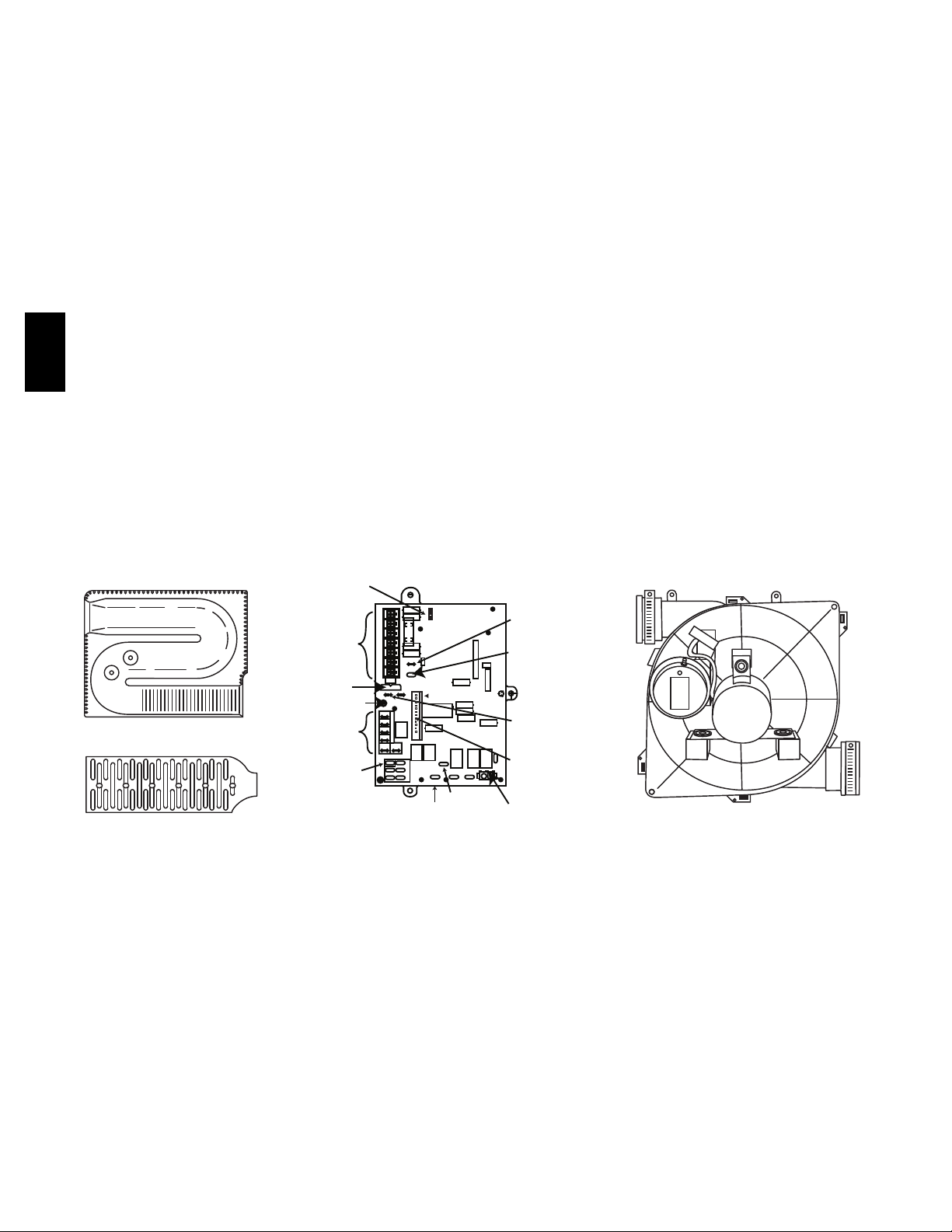
BLOWER OFF-DELAY
T1 DHUM G COM W TIT2 R
115-VAC (L2)
NEUTRAL
CONNECTIONS
24V
SPARE 2SPARE 1
A92505
24-V THERMOSTAT
TERMINALS
3-AMP FUSE
LED OPERATION
& DIAGNOSTIC LIGHT
BLOWER SPEED
SELECTION
TERMINALS
SEC-2 SEC-1
COM 24VAC
COM
HEAT
COOL
FAN
EAC-2
Monoport Burners — The burners are finely tuned for smooth,
quiet combustion plus economical gas usage.
Slow Opening Redundant Gas Valve — Shuts off gas to burners
if any of the valves fails to close completely for any reason. The
slow opening feature reduces start--up noise from rapid ignition.
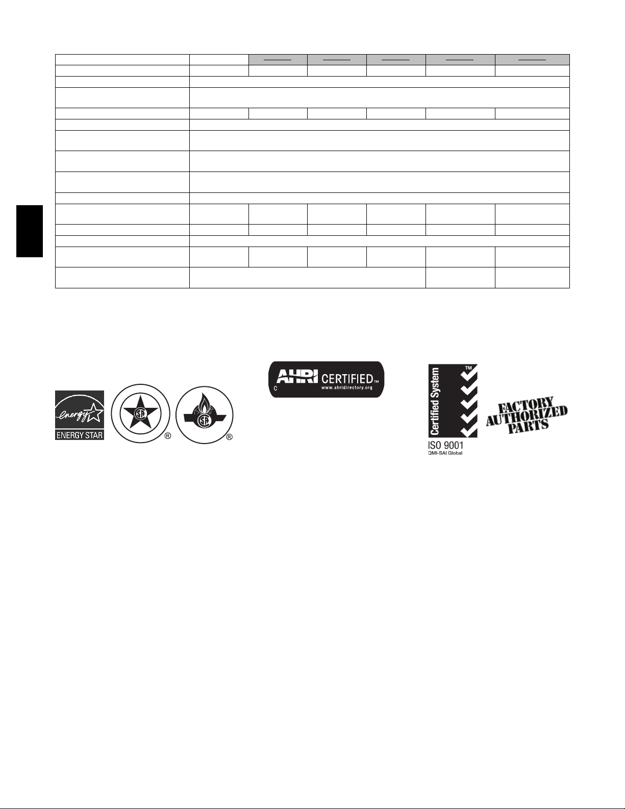
Quality Registration —ThePlus 90x is engineered and
manufactured under an ISO 9001 registered quality system.
Certifications —ThePlus 90x Model units are CSA (A.G.A.
and C.G.A.) design certified for use with natural and propane
gases. The furnace is factory--shipped for use with natural gas. A
CSA (A.G.A./C.G.A.) listed gas conversion kit is required to
convert furnace for use with propane gas. The efficiency is
GAMA efficiency rating certified. The Plus 90x meets California
Air Quality Management District emission requirements. Refer to
Vent Table, for elevation limitations.
BLOWER OFF-DELAY
90 150
120 180
PLT
TEST / TWIN
HUH
PL1
24V MTR TAPS
1
EAC-1
L1 BL-1 PR-1
EAC-1 TERMINAL
(115-VAC 1.0 AMP. MAX0
115-VAC (LI)
NUETRAL
CONNECTIONS
PL2
PL1-HOT SURFACE
IGNITER & INDUCER
MOTOR CONNECTION
TWINNING AND/OR
COMPONENT TEST
TERMINAL
HUMIDIFIER TERMINAL
(24-VAC 0.5 AMP. MAX
TRANSFORMER
24-VAC CONNECTION
PL1-LOW VOLTAGE
MAIN HARNESS
CONNECTOR
A08345
)
S
A02172
2
1
13
2
3
4
6
7
8
9
10
11
12
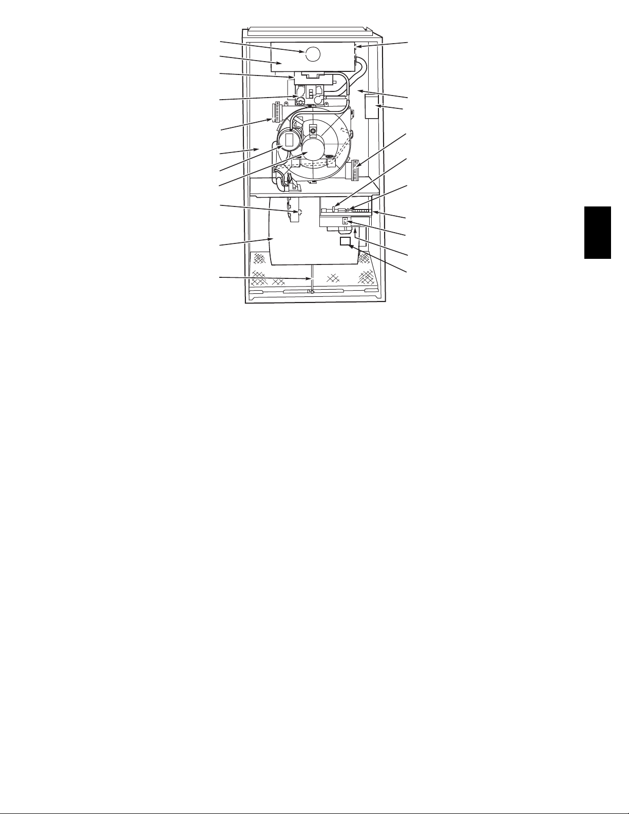
1. Burner sight glass for viewing burner flame.
2. Burner assembly (inside), operates with energy--sav-
ing, inshot burners and hot surface igniter for safe,
dependable heating.
14
5
6
15
16
17
18
19
20
A08421
11. Heavy--duty blower circulates air across the heat
exchangers to transfer heat into the home.
12. Air filter and retainer may be used for side or bottom
return application.
353AAV
3. Combustion--air intake connection to ensure contam-
inant--free air (right or left side).
4. Redundant gas valve, safe, efficient, features 1 gas
control with 2 internal shutoff valves.
5. Junction box for 115--v electrical power supply.
(right or left side)
6. Vent outlet uses sealed PVC pipe to carry vent gases
from the furnace’s combustion system (right or left
side).
7. Secondary condensing heat exchanger (inside),
wrings out more heat through condensation of gases.
Constructed with polypropylene--laminated steel to
ensure durability.
8. Pressure switch ensures adequate flow of flue
products through furnace and out vent system.
9. Inducer motor pulls hot flue gases through the heat
exchangers, maintaining negative pressure for added
safety.
13. Rollout switch (manual reset) to prevent overtemper-
ature in burner area.
14. Primary serpentine heat exchanger (inside). Stretches
fuel dollars with the S--shaped heat--flow design. Solid weld--free construction of corrosion--resistant aluminized steel means reliability.
15. A 3--amp fuse provides electrical and component
protection.
16. Light emitting diode (LED) on control center. Code
lights are for diagnosing furnace operation and service requirements.
17. Control center.
18. Blower access panel safety interlock switch.
19. Transformer (24v) behind control center provides
low--voltage power to furnace control center and
thermostat.
20. Power choke (used with 1 HP and 3/4 HP motors.)
10. Condensate drain connection collects moisture con-
densed during the combustion process.
123456
3
PHYSICAL DATA
**Note: 060--120 Sizes are phasing out.**
UNIT SIZE 036040 036060 036080 048080 060100 060120
SHIPPING WEIGHT LB. (KG) 175 (47) 182 (57) 198 (64) 205 (69) 232 261 (74)
LIMIT CONTROL SPST
HEATING BLOWER CONTROL
(Off Delay)
BURNERS (Monoport) 2 3 4 4 5 6
GAS CONNECTION SIZE 1/2--- in. NPT
GAS VALVE(Redundant)
Manufacturer
Minimum Inlet Pressure
(in. wc)
Maximum Inlet Pressure
(in. wc)
IGNITION DEVICE Hot Surface
DIRECT---DRIVE MOTOR
( E C M X --- 1 3 )
1/2 1/2 1/2 3/4 1 1
MOTOR FULL LOAD AMPS 6.8 6.8 6.8 8.4 10.9 10.9
R P M ( N o m i n a l ) --- S P E E D S 1050--- 5
353AAV
BLOWER WHEEL DIAMETER X
W I D T H --- I N ( m m )
F I L T E R S I Z E ( W a s h a b l e ) --IN (mm)
10 X 7
(254 X 178)
10 X 7
(254 X 178)
(1) 16 X 25 X 3/4
(406 X 635 X 19)
Solid--- Sta te Time Operation
W h it e --- R o d g e rs
4.5 (Natural Gas)
13.6 (Natural Gas)
10 X 7
(254 X 178)
11 X 8
(279 X 203)
11 X 10
(279 X 254)
(1) 20 X 25 X 3/4
(508 X 635 X 19)
11 X 10
(279 X 254)
(1) 24 X 25 X 3/4
(610 X 635 X 19)
I
G
S
E
N
D
Always Ask For
Use of the AHRI Certified TM Mark indicates a
C
E
R
D
E
I
T
F
I
CERTIFIED
manufacturer’s participation in the program. For
verification of certification for individual products,
go to www.ahridirectory.org.
4
BRYANT ACCESSORIES*
ACCESSORIES
GAS CONVERSION KIT --NATURAL TO PROPANE
GAS CONVERSION KIT --PROPANE TO NATURAL
MANUFACTURED (MOBILE)
HOME KIT
DOWNFLOW BASE
(For Combustible Floors)}
VENT TERMINATION KIT
(Bracket Only for 2 Pipes)
CONCENTRIC TERMINATION
KIT (Single Exit)
CONDENSATE FREEZE
PROTECTION KIT
CONDENSATE NEUTRALIZER
KIT (Obtained thru RCD)
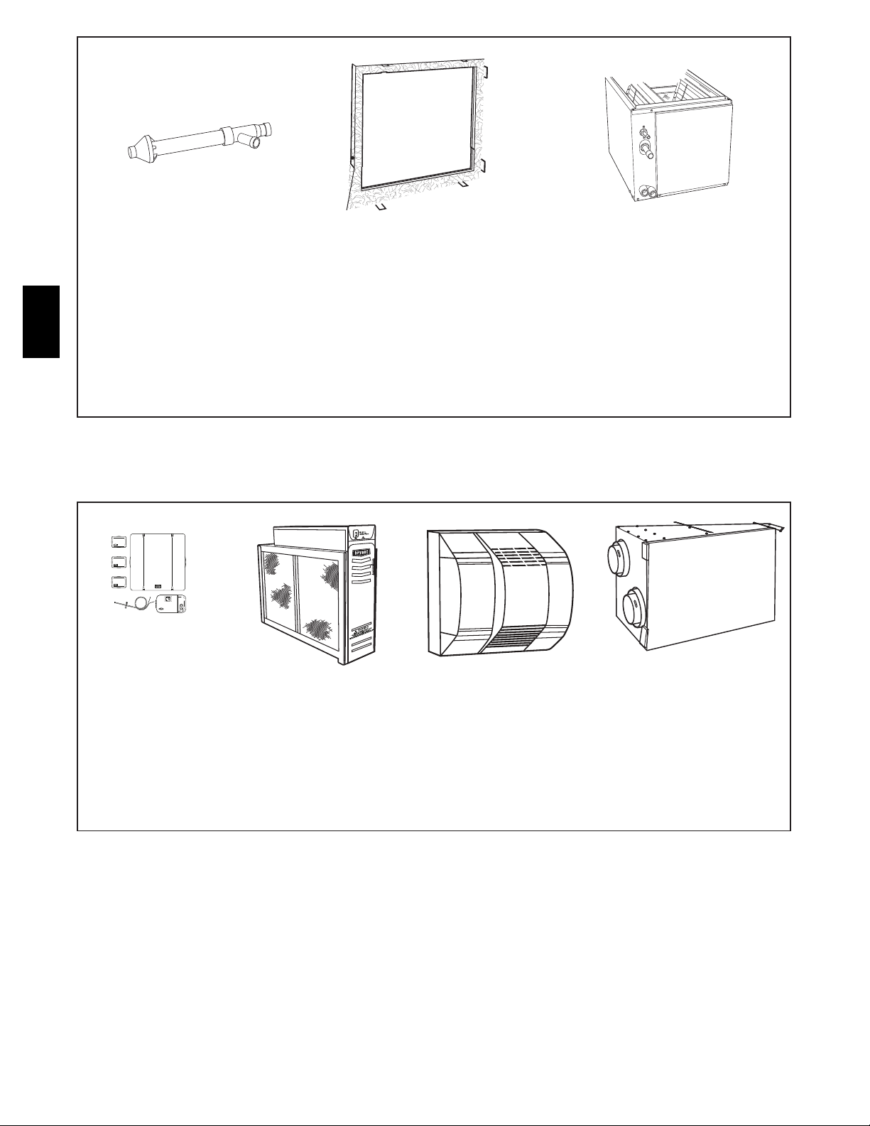
ELECTRONIC AIR CLEANER
(EAC)
AIR PURIFIER Models GAPAAXBB1625, GAPAAXBB2025
MECHANICAL AIR CLEANER Models EZXCAB, FILCAB
HUMIDIFIER Model HUM
HEAT RECOVERY VENTILATOR Model HRV
ENERGY RECOVERY
VENTILATOR
UV LIGHTS Model UVL
VENT/EXHAUST PIPE
EXTERNAL TRAP KIT
DOOR GASKET KIT KGBAC0110DGK
UNFRAMED FILTER,
PERMANENT WASHABLE 3/4”
(19mm)
16 x 25 (406 x 635 mm)
UNFRAMED FILTER,
PERMANENT WASHABLE 3/4”
(19mm)
16 x 25 (508 x 635 mm)
UNFRAMED FILTER,
PERMANENT WASHABLE 3/4”
(19mm)
16 x 25 (610 x 635 mm)
F o r u s e w i t h 1 --- s p e e d A i r C o n d i t i o n e r --- d e g . F / C , A u t o Ch a n g e o v e r --- T 6 --- N A C , T 2 --- N A C
T H E R M O S T A T --NON---PROGRAMMABLE
T H E R M O S T A T --PROGRAMMABLE
ZONING CONTROL
*Factory---authorized and field---installed. Gas conversion kits are CSA (A.G.A./C.G.A.) recognized
Required for installation on combustible floors when no coil box is used, or when any coil box other than a Bryant cased coil is used.
*Model HP and 2S thermostat must be field converted to air conditioner operation.
{Thermidistatt Contro
}Dual Fuel thermostat is used with furnace and heat pump application.
l control can be configured for multiple use and staging. It must be configured for each specific application.
F o r u s e w i t h 1 --- s p e e d A i r C o n d i t i o n e r --- d e g . F / C , A u t o Ch a n g e o v e r --- T 6 --- N H P --- T 2 --- N H P *
F o r u s e w i t h 2 --- s p e e d A i r C o n d i t i o n e r --- d e g . F / C , A u t o Ch a n g e o v e r --- T 6 --- N R H *
For use with multi--- use / stage configurations --- deg. F/C, Auto Changeover/Temperature and
H u m i d i t y Co n t r o l --- T 6 --- P R H
F o r u s e w i t h 1 --- s p e e d A i r C o n d i t i o n e r --- d e g . F / C , A u t o Ch a n g e o v e r , 7 --- D a y P r o g r a m m a b l e ---
T 6 --- P A C
F o r u s e w i t h 1 --- s p e e d A i r C o n d i t i o n e r --- d e g . F / C , A u t o Ch a n g e o v e r , 7 --- D a y P r o g r a m m a b l e ---
T6---PHP*
F o r u s e w i t h 2 --- s p e e d A i r C o n d i t i o n e r --- d e g . F / C , A u t o Ch a n g e o v e r , 7 --- D a y P r o g r a m m a b l e ---
T 6 --- P R H *
F o r u s e w i t h 1 --- s p e e d A i r C o n d i t i o n e r --- d e g . F / C , 5 --- 2 Da y P r o g r a m m a b l e --- T2 --- P A C
F o r u s e w i t h mu l t i --- s t a g e a p p l i c a t i o n s --- d e g . F / C , A u t o C h a n g e o v e r, 7 --- D a y Pr o g r a m m a b l e ---
T 6 --- P H P
F o r m u l t i --- u s e / s t a g e c o n f i g u r a t i o n s --- d e g . F / C , A u t o C h a n g e o v e r , 7 --- D a y P r o g r a m m a b l e /
Temperature and Humidity Control --- T6 --- PRH
Comfort Series Three---Zone Zone Kit --- ZONEBB3ZAC01, ZONEBB3ZHP01
2---Performance Series Zoning/Temperature and Humidity Control --- ZONEBB2KIT01 --- B
4---Performance Series Zoning/Temperature and Humidity Control --- ZONEBB4KIT01 --- B
8---Performance Series Zoning/Temperature and Humidity Control --- ZONEBB8KIT01 --- B
}
2---IN. --- KGAVT0101BRA 3---IN. --- KGAVT0201BRA
2---IN. ---KGAVT0701CVT 3 --- IN. --- KGAVT0801CVT
{
KGANP4601ALL
KGANP3901ALL
KGAMH0301KIT
KGASB0301ALL
KGAHT01010CFP
P908---0001
Model EACB
Model ERV
KGAET0106ETK
KGAWF1301UFR
KGAWF1401UFR
KGAWF1501UFR
{
353AAV
5
CONCENTRIC
VENT (DIRECT VENT/
2-PIPE ONLY)
A concentric vent kit allows vent
and combustion-air pipes to
terminate through a single exit
in a roof or side wall.
353AAV
One pipe runs inside the other
allowing venting through the
inner pipe and combustion air to
be drawn in through the outer
A93086
DOWNFLOW
SUBBASE
One base fits all furnace sizes.
The base is designed to be installed between the furnace and a
combustible floor when no coil
box is used or when a coil box
other than a Bryant cased coil is
used. It is CSA (A.G.A./C.G.A.)
design certified for use with select
Bryant furnaces when installed in
downflow applications.
A88202
BRYANT CASED
A96214
N-COIL
(as shown)
The Bryant Cased N-Coil or
A-Coil is an upflow/downflow
furnace coil which can also
replace the downflow subbase
when installing select Bryant
furnaces on combustible flooring
in the downflow orientation.
pipe.
A08450
A97432
CONTROLS:
THERMOSTATS
AND ZONING
Available in programmable and
non-programmable models,
Bryant thermostats maintain a
constant, comfortable temperature level in the home.
For the ultimate in home comfort,
Bryant’s 2, 4, and 8-zone systems
allow temperature control of individual “zones” of the home. This is
accomplished through a series of
electronic dampers and
remote room sensors.
4-zone system is shown.
The
C04009
MECHANICAL
OR ELECTRONIC
AIR CLEANER
Cleans the air of smoke, dirt, and
many pollens commonly found.
Saves decorating and cleaning
expenses by keeping carpets,
furniture, and drapes cleaner.
Electronic air cleaner is shown.
A01484
HUMIDIFIER
By adding moisture to winter-dry
air, a Bryant humidifier can often
improve comfort and keep
furniture, rugs, and draperies in
better condition. Moisturizing
household air also helps to retain
normal body heat and provides
comfort at lower temperatures.
ENERGY/HEAT RECOVERY
VENTILATOR
Bryant’s energy or heat recovery
ventilators exhaust stale indoor
air and provide fresh outdoor air
to the home while minimizing
heat loss and humidity level.
Especially useful for today’s
tighter constructed houses.
Energy recovery ventilator
is shown.
A08153
6
(21mm)
UNIT SIZE A D E
040-12 / 036040 17-1/2 (
445) 15-7/8 (403) 16 (406)
060-12 / 036060 17-1/2 (445) 15-7/8 (4
03) 16 (406)
080-12 / 036080 17-1/2 (445) 15-7/8 (
40
3) 16 (406)
080-16 / 048080 17-1/2 (445) 15-7/8 (403) 16 (406)
100-20 / 060100 21 (25.4) 19-3/8 (492) 19-1/2 (
4
95)
120-20 / 060120 24-1/2 (622)
22-7/8 (581) 23 (584)
(16mm)
"
"
16
⁄
8
⁄
5
13
"
8
⁄
"
16
⁄
5
(8mm)
7
39
(1013mm)
1"
(25mm)
1mm)
(1
"
16
⁄
7
(17mm)
"
16
⁄
11
(694mm)
"
(724mm)
16
⁄
"
2
⁄
15
1
26
28
5
(667mm)
"
4
⁄
1
26
"
16
⁄
9
LOW
A
AIRF
(567mm)
(483mm)
"
"
16
⁄
19
22
TYP
(14mm)
"
16
⁄
13
D
"
16
⁄
13
OUTLET
2-IN. COMBUSTION-
ATE DRAIN
LOCATION
P
TRA
CONDENS
OUTLET
(21mm) (21mm)
W &
ATION
ATE DRAIN
O
LOC
OWNFL
HORIZONTAL LE FT)
(D
TRAP
CONDENS
A
DI
.
-IN
2
⁄
GAS CONN
1
AIR CONN
TE
A
LOW &
TERN
WNF
A GAS CONN
(DO
OR AL
-IN. DI
2
⁄
1
HORIZONTAL RIGHT)
(22mm)
-IN. DIA
8
⁄
POWER CONN
7
WER CONN
-IN. DIA
8
⁄
PO
7
"
4
⁄
1
TYP
33
A
DI
.
-IN
2
⁄
1
(845mm)
"
16
⁄
13
30
(783mm)
TRY
EN
CONN
T
TAT
VEN
.
2-IN
THERMOS
"
2
⁄
1
30
(775mm)
"
8
⁄
5
32
"
16
⁄
P
1
1
TY
29
(754mm)
Y
R
Y
(22mm)
. DIA
-IN
8
⁄
POWER ENT
ACCESSOR
7
P
TY
"
8
⁄
5
27
1
1
(702mm)
CONDENSATE
"
16
⁄
22
(829mm)
"
16
⁄
9
TYP
"
27
2
(700mm)
⁄
1
24
TE
A
ATION
LOW)
ALTERN
UPF
(
LOC
DRAIN TRAP
SIDE INLET
"
4
⁄
1
18
(464mm)
"
(622mm)
16
⁄
5
17
(440mm)
"
16
⁄
7
TYP
9
(240mm)
" TYP
4
⁄
1
(565mm)
22
ATION
CONDENSATE
DRAIN LOC
"
16
⁄
11
T
E
INLE
"
16
⁄
11
TE
A
CONDENS
"
16
⁄
3
24
W)
O
L
(UPF
(17mm)
(17mm)
TION
A
(UPFLOW)
DRAIN LOC
TOM INLET
(614mm)
T
O
B
HANGING
FOR HORIZONTAL
DIMPLE LOCATORS
.
e.
rectangl
.
s
-in. (495mm) rectangle
2
/
. (305mm)
1
1
x 19
x 12-in
alent diameter
v
(368mm)
2
(368mm)
/
2
1
/
1
1
round or 14
round or 14
acturer‘s recommendation for equi
f
u
n
n-air openings at furnace, based on metal duct. If flex duct is used,
rn-air opening at furnace:
r
um retu
um retu
m
b. For 1200 CFM 20-in . (508mm)
a. For 800 CFM 16-in . (406mm)
see flex duct ma
2. Mini
NOTES: 1. Minim
.
e
rectangl
.(591mm)
-in
4
nsure adequate
/
y table in Product Data
r
x 23
(368mm)
2
/
s. The use of both side inlets, a
round or 14
ve 1800 CFM, see Air Delive
o
ature for specific use of single side inlet
r
return air openings for airflow requirements above 1800 CFM at 0.5 in. W.C. ESP.
combination of 1 side and the bottom, or the bottom only will e
lite
d. For airflow requirements ab
c. For 1600 CFM 22-in .(559mm)
353AAV
(684mm)
"
16
⁄
15
26
(667mm)
"
4
⁄
1
26
"
2
⁄
1
24
(666mm)
(567mm)
"
16
⁄
5
22
(51mm)
BUSTION-
COM
-IN.
2
AIR CONN
(13mm)
-IN. DIA
2
⁄
1
GAS CONN
CONN
T
VEN
.
-IN
(51mm)
2
T
A
RY
ENT
"
16
⁄
1
1
22
(576mm)
THERMOST
. DIA
(13mm)
-IN
2
⁄
1
SIDE INLET
"
2
⁄
P
1
TY
14
(368mm)
(591mm)
P
TY
"
4
⁄
1
23
1"
(32mm)
"
4
⁄
1
1
7
(684mm)
P
TY
"
16
SIDE INLET
⁄
15
26
(25mm)
A08321

DOWNFLOW SUBBASE DIMENSIONS -- IN. (MM)
4
3
2
1
1
2
3
4
FURNACE
CASING
FURNACE IN DOWNFLOW APPLICATION
WIDTH
17-1/2
(445)
21
(533)
24-1/2
(622)
*The plenum should be constructed 1/4 -- -in. (6 mm) smaller in width and depth than the plenum dimensions shown above.
Furnace with or without Cased Coil Assembly or
Furnace with or without Cased Coil Assembly or
Furnace with or without Cased Coil Assembly or
Coil Box
Coil Box
Coil Box
1 1/4″ (32 μμ) TYP
PLENUM
OPENING
PLENUM OPENING FLOOR OPENING
A B C D
15--- 1/8
(384)
18--- 5/8
(473)
22-1/8
(562)
19 (483)
LOCATING
TAB
19
(483)
19
(483)
B
16-3/4
(425)
20--- 1/4
(514)
23-3/4
(603)
20--- 3/8
(518)
20--- 3/8
(518)
20--- 3/8
(518)
HOLE NO.
FOR
WIDTH
A D J U S T ---
MENT
3
2
1
353AAV
FACTORY-SUPPLIED
FIELD-INSTALLED
INSULATION
A
LOCATING
TAB
C
D
COMBUSTION--AIR PIPE FOR NON--DIRECT VENT (1--PIPE) APPLICATION
(SIZES 040 THROUGH 120 ONLY)
FIELD-SUPPLIED
2-IN. (51 mm) DIA.
PVC 90° ELBOW
FIELD-SUPPLIED
2-IN. (51 mm) DIA.
PVC PIPE
LENGTH OF STRAIGHT
PIPE PORTION OF COMBUSTION
AIR INLET PIPE ASSEMBLY - IN. (mm)
CASING WIDTH A
17-1/2 8-1/2 ± 1/2 (216 ± 13 mm)
(445 mm)
21 (533 mm)
24-1/2 (622 mm)
10-1/2 ± 1/2 (267 ± 13 mm)
12 ± 1/2 (305 ± 13 mm)
COMBUSTION-AIR DISC
(FACTORY-SUPPLIED IN
LOOSE PARTS BAG)
A
A96211
CONCENTRIC VENT FOR DIRECT VENT (2--PIPE) APPLICATION (ALL MODEL SIZES)
B IN. (MM) DIA PVC
VENT/EXHAUST
F
E
C IN. (MM) DIA
13/
16 (30 mm)
1
1/2
(38 mm)
D
A
B IN. (MM) DIA PVC
INTAKE/COMBUSTION AIR
KITPARTNO. A* B C D{ E F
KGAVT0701CVT 33--- 3/8 (848) 2 (51) 3---1/2 (89) 16--- 5/8 (422) 6--- 1/4 (159) 5 --- 3/4 (146)
KGAVT0801CVT 38--- 7/8 (987) 3 (76) 4--- 1/2 (114) 21--- 1/8 (537) 7 ---3/8 (187) 6---1/2 (165)
*Dimension A will change accordingly as Dimension D is lengthened or shortened.
{Dimension D may be lengthened to 60--- in. (1524 mm) maximum. Dimensio n D may also be shortened by cutting the pipes provided in the kit to 12 --- in. (305
mm) minimum.
8

CONDENSATE TRAP
353AAV
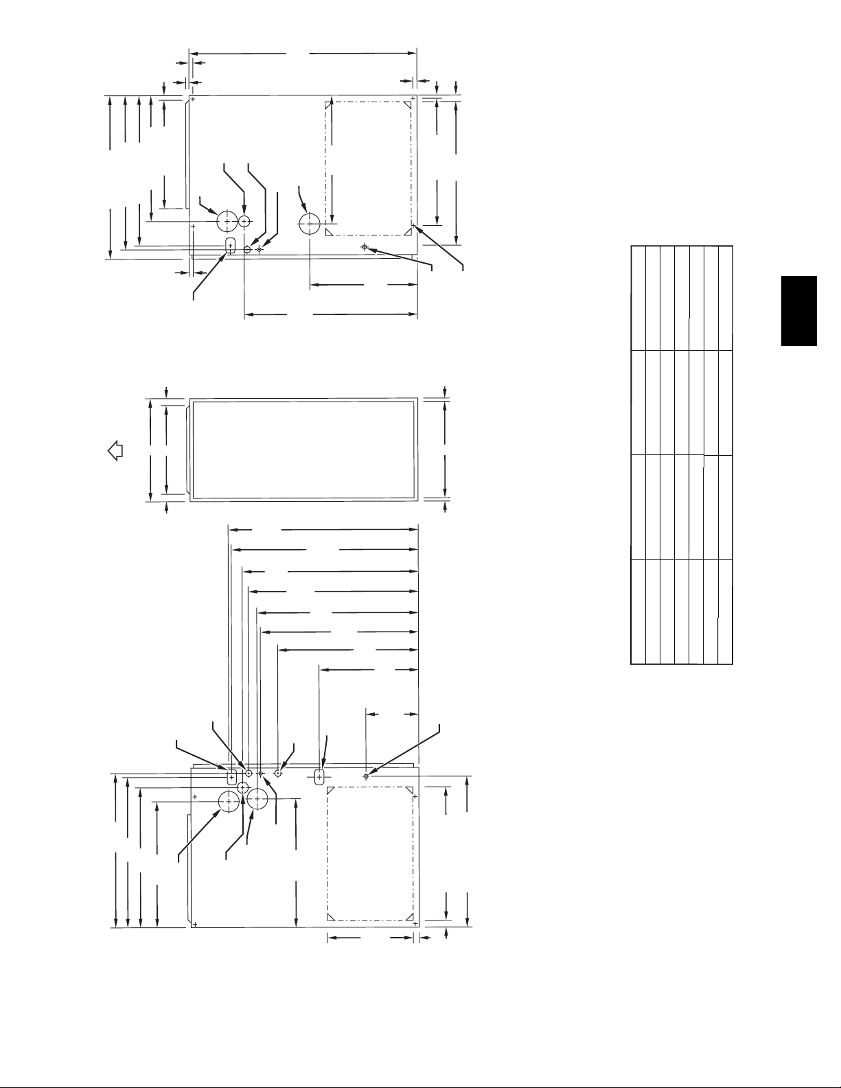
MEDIA FILTER CABINET
5
/
23
8
" (600 mm)
3
/
8
" (594 mm)
23
Furnace Side
3
/
23
4
Centerline Screw Slots
" (603 mm)
3
/
5
4
(146 mm)
Opening with Flanges Bent
A
Duct Side
Media
Filter Cabinet
16" (406)
20" (508)
AB
17" (432) 16" (406)
21" (533) 20" (508)
24" (610) 25" (635) 24" (610)
5
/
8
25
3
/
24
8
1
/
23
8
Opening
" (651 mm)
" (619 mm)
" (587 mm)
Shipped with sizes
040-08, 040-12, 060-08, 060-12,
060-16, 080-12, 080-16
080-20, 100-16, 100-20
120-20, 140-20
A93026
gninepO B
A05186
9

CLEARANCE TO COMBUSTIBLES
353AAV
335122-201 REV. B LIT TOP
10
A08435

PERFORMANCE DATA
EFFICIENCY
UNIT SIZE 036040 036060 036080 048080 060100 060120
CAPACITY* Direct Vent (2--- pipe)
(Shaded capacities are specified on
the rating plate)
CAPACITY* Non---Direct vent (1---pipe)
AFUE* Direct Vent (2 --- pipe)
N o n --- w e a th e ri z e d I CS
A F UE * N o n --- D ir e ct Ve n t ( 1 --- p ip e )
Non-weatherized ICS
Input Btuh {
UNIT SIZE 036040 036060 036080 048080 060100 060120
CERTIFIED TEMPERATURE RANGE --_F(_C)
CERTIFIED EX STATIC PRESSURE
(in. wc)
AIRFLOW (CFM)}
*Capacity and AFUE in accordance with U.S. Government DOE test procedures.
{Gas input ratings are certified for elevations to 2000 ft. (610 M). For elevations above 2000 ft. (610 M), reduce ratings 2% for each 1000 ft. (305 M) abovesea
level. In Canada, derate the unit 5% for elevations 2000 to 4500 ft. (610 to 1372 M) above sea level.
}Airflow shown is for bottom only return --- air supply with factory supplied 3/4 ---in. (19 mm) washable filter(s).
For air delivery above 1800 CFM, see Air Delivery table for other options.
An airflow reduction of up to 7% may occur when using the factory ---specified 4 5/16---in. (110 mm) wide, high efficiency media filter.
For best furnace efficiency when using the 4 --- 5/16 ---in. (110 mm) wide media filter, adjust the blower speed tap to near the mid--- point of the rise range.
ICS --- Isolated Combustion System.
Upflow 38000 56000 75000 75000 94000 113000
Downflow 38000 56000 75000 75000 94000 113000
Horizontal 38000 56000 74000 75000 93000 112000
Upflow 38000 56000 75000 75000 94000 113000
Downflow 38000 56000 74000 75000 93000 112000
Horizontal 38000 56000 74000 75000 93000 112000
Upflow 95 93
Downflow 93.6 91.5
Horizontal 94.4 92.3
Upflow 94.7 92.4
Downflow 93.3 91.4
Horizontal 94.1 91.4
40000 60000 80000 80000 100000 120000
20--- 50
( 1 1 --- 2 8)
Heating 0.10 0.12 0.15 0.15 0.20 0.20
Cooling 0.50 0.50 0.50 0.50 0.50 0.50
Heating 845 1040 1180 1450 1890 2065
Cooling 1260 1250 1240 1620 1635 1925
30--- 60
( 1 7 --- 3 3)
40--- 70
( 2 2 --- 3 9)
30--- 60
( 1 7 --- 3 3)
30--- 60
( 1 7 --- 3 3)
40--- 70
( 2 2 --- 3 9)
353AAV
11

AIR DELIVERY—CFM (WITH FILTER)
UNIT
SIZE
RETURN-AIR
SUPPLY
SPEED
0.1 0.2 0.3 0.4 0.5 0.6 0.7 0.8 0.9 1
EXTERNAL STATIC PRESSURE (in.wc)
5(Gry) 1425 1385 1350 1305 1260 1210 1165 1100 995 855
4(Yel) 1215 1165 1130 1085 1025 970 905 840 795 730
036040
SIDE/BOTTOM
3(Blu) 1060 1005 960 910 845 790 715 660 610 560
2(Org) 890 835 770 695 640 570 510 450 355 235
1(Red) 880 675 570 475 425 335 245 - - -
5(Gry) 1430 1390 1345 1300 1250 1205 1150 1080 995 845
3(Blu) 1240 1200 1145 1100 1040 975 915 860 790 730
036060
SIDE/BOTTOM
4(Yel) 1090 1030 980 935 850 800 730 665 590 525
1(Red) 900 835 780 705 635 565 490 410 335 200
2(Org) 805 620 440 380 300 - - - - -
5(Gry) 1400 1360 1325 1285 1240 1205 1160 1125 1075 1000
353AAV
036080
SIDE/BOTTOM
3(Blu) 1340 1300 1265 1215 1180 1135 1100 1055 1015 965
4(Yel) 1195 1160 1115 1065 1025 985 935 895 850 800
1(Red) 1025 980 935 880 835 795 745 685 635 585
2(Org) 855 800 745 680 635 560 515 460 420 360
5(Gry) 1720 1695 1690 1655 1620 1580 1540 1495 1465 1415
3(Blu) 1565 1535 1530 1490 1450 1420 1375 1335 1295 1255
048080
SIDE/BOTTOM
4(Yel) 1330 1310 1270 1220 1180 1135 1095 1055 1010 970
2(Org) 1210 1180 1135 1085 1035 995 950 910 865 810
1(Red) 1110 1065 1005 960 910 865 820 770 720 670
5(Gry) 2070 2020 1985 1925 1890 1850 1795 1755 1690 1610
3(Blu) 1815 1775 1730 1690 1635 1595 1555 1500 1460 1410
060100
SIDE/BOTTOM
4(Yel) 1580 1535 1480 1440 1380 1380 1340 1285 1235 1185
2(Org) 1380 1325 1275 1220 1220 1165 1105 1060 1000 960
1(Red) 1170 1105 1055 985 935 870 805 765 705 660
5(Gry) 2250 2205 2155 2110 2065 2020 1970 1925 1870 1790
3(Blu) 2130 2085 2030 1980 1925 1880 1830 1775 1730 1675
060120
SIDE/BOTTOM
4(Yel) 1890 1835 1790 1740 1690 1640 1590 1535 1480 1435
1(Red) 1640 1585 1525 1475 1425 1365 1315 1260 1200 1140
2(Org) 1420 1370 1305 1255 1190 1135 1065 1010 940 880
] • Airflow shown is for bottom only return --- air supply with factory supplied 3/4 ---in. (19 mm) washable filter(s).
For air delivery above 1800 CFM, see Air Delivery table for other options.
An airflow reduction of up to 7% may occur when using the factory ---specified 4 5/16---in. (110 mm) wide, high efficiency media filter.
For best furnace efficiency when using the 4 5/16 --- in. (110 mm) wide media filter, adjust the blower speed tap to near the mid --- point of the rise range.
For horizontal and downflow applications, use one side or bottom or bottom only as airflow reference.
12

COMBUSTION--AIR AND VENT PIPING FOR DIRECT VENT/2--PIPE (ALL SIZES) AND
NON--DIRECT VENT/1--PIPE (SIZES 040 THROUGH 120 ONLY) APPLICATIONS
NON-DIRECT
ALTITUDE
FT (M)
0 to 2000
(0 to 610)
ALTITUDE
FT (M)
2001 to 3000
(610 to 914)
See notes at end of table.
UNIT SIZE
UNIT SIZE
(BTUH)
40,000
60,000
80,000
100,000
120,000
(BTUH)
40,000
60,000
80,000
100,000
120,000
DIRECT VENT (2-PIPE) ONLY
TERMINATION
TYPE
2Pipeor2-in
Concentric
2Pipeor2-in
Concentric
2Pipeor2-in
Concentric
2Pipeor3-in
Concentric
2Pipeor3-in.
Concentric
DIRECT VENT (2-PIPE) ONLY
TERMINATION
TYPE
2Pipeor2-in
Concentric
2Pipeor2-in
Concentric
2Pipeor2-in
Concentric
2Pipeor3-in
Concentric
2Pipeor3-in.
Concentric
PIPE DIA
IN. (mm)*
1 (25) 1 (25)
1-1/2 (38) 1-1/2 (38)
2 (51) 2 (51)
1-1/2 (38) 1-1/2 (38)
2 (51) 2 (51)
1-1/2 (38) 1-1/2 (38)
2 (51) 2 (51)
2-1/2 (64) 2-1/2 (64)
2 (51) 2 (51)
2-1/2 (64) 2-1/2 (64)
3 (76) 3 (76)
2-1/2 (64)
one disk
3 (76)† NA
3 (76) † no disk 3 (76)†
PIPE DIA
IN. (mm)*
1-1/2 (38) 1-1/2 (38)
2 (51) 2 (51)
1-1/2 (38) 1-1/2 (38)
2 (51) 2 (51)
2 (51) 2 (51)
2-1/2 (64) 2-1/2 (64)
2-1/2 (64) 2-1/2 (64)
3 (76) 3 (76)
3 (76) NA
3 (76)† no disk NA
4 (102)† no
NA 3 (76)†
disk
VENT (1-PIPE)
ONLY
PIPE DIA
IN. (mm)*
2-1/2 (64)
NON-DIRECT
VENT (1-PIPE)
ONLY
PIPE DIA
IN. (mm)*
4 (102)† no disk
NUMBER OF 90° ELBOWS
1 2 3 4 5 6
5
(1.5)
(21.3)70(21.3)65(19.8)60(18.3)60(18.3)55(16.8)
(21.3)70(21.3)70(21.3)70(21.3)70(21.3)70(21.3)
(6.1)15(4.6)10(3.0)5(1.5)
(21.3)70(21.3)70(21.3)70(21.3)70(21.3)70(21.3)
(3.0)
(16.8)50(15.2)35(10.7)30(9.1)30(9.1)20(6.1)
(21.3)70(21.3)70(21.3)70(21.3)70(21.3)70(21.3)
(1.5)
(12.2)30(9.1)20(6.1)20(6.1)10(3.0)
(21.3)70(21.3)70(21.3)70(21.3)70(21.3)70(21.3)
(3.0)
(13.7)40(12.2)35(10.7)30(9.1)25(7.6)20(6.1)
(21.3)70(21.3)70(21.3)70(21.3)70(21.3)70(21.3)
(20.4)62(18.9)57(17.4)52(15.8)52(15.8)47(14.3)
(21.3)70(21.3)70(21.3)70(21.3)70(21.3)70(21.3)
(5.2)12(3.7)7(2.1)
(21.3)67(20.4)66(20.1)61(18.6)61(18.6)61(18.6)
(14.9)44(13.4)30(9.1)25(7.6)25(7.6)15(4.6)
(21.3)70(21.3)70(21.3)70(21.3)70(21.3)70(21.3)
(10.7)26(7.9)16(4.9)16(4.9)6(1.8)
(21.3)70(21.3)70(21.3)70(21.3)66(20.1)61(18.6)
(4.3)9(2.7)
(19.2)62(18.9)62(18.9)61(18.6)61(18.6)61(18.6)
(21.3)70(21.3)63(19.2)56(17.1)50(15.2)43(13.1)
(21.3)70(21.3)70(21.3)70(21.3)70(21.3)70(21.3)
NA NA NA NA NA
70
70
20
70
10
NA NA NA NA NA
55
70
5
NA NA NA NA NA
40
70
10
NA NA NA NA NA
45
70
NUMBER OF 90° ELBOWS
1 2 3 4 5 6
67
70
17
70
49
70
35
70
14
63
70
70
NA NA NA NA
NA NA NA
NA NA
353AAV
NA
NA
13

COMBUSTION--AIR AND VENT PIPING FOR DIRECT VENT/2--PIPE (ALL SIZES) AND
NON--DIRECT VENT/1--PIPE (SIZES 040 THROUGH 120 ONLY) APPLICATIONS (CON’T.)
NON-DIRECT
ALTITUDE
FT (M)
3001 to 4000
(914 to 1219)
353AAV
ALTITUDE
FT (M)
4001 to 5000‡
(1219 to 1524)
See notes at end of table.
UNIT SIZE
(BTUH)
40,000
60,000
80,000
100,000
120,000
UNIT SIZE
(BTUH)
40,000
60,000
80,000
100,000
120,000
DIRECT VENT (2-PIPE) ONLY
TERMINATION
TYPE
2Pipeor2-in
Concentric
2Pipeor2-in
Concentric
2Pipeor2-in
Concentric
2Pipeor3-in
Concentric
2Pipeor3-in.
Concentric
4† no disk
DIRECT VENT (2-PIPE) ONLY
TERMINATION
TYPE
2Pipeor2-in
Concentric
2Pipeor2-in
Concentric
2Pipeor2-in
Concentric
2Pipeor3-in
Concentric
2Pipeor3-in.
Concentric
PIPE DIA
IN (mm)*
1-1/2 (38) 1-1/2 (38)
2 (51) 2 (51)
1-1/2 (38) 1-1/2 (38)
2 (51) 2 (51)
2 (51) 2 (51)
2-1/2 (64) 2-1/2 (64)
2-1/2 (64) 2-1/2 (64)
3 (76) 3 (76)
3 (76)† no disk NA
4 (102)† no
PIPE DIA
IN. (mm)*
1-1/2 (38) 1-1/2 (38)
2 (51) 2 (51)
1-1/2 (38) 1-1/2 (38)
2 (51) 2 (51)
2 (51) 2 (51)
2-1/2 (64) 2-1/2 (64)
2-1/2 (64) 2-1/2 (64)
3 (76) 3 (76)
3 (76)†
no disk
4 (102)† no
NA 3 (76)†
disk
NA 3 (76)†
disk
VENT (1-PIPE)
ONLY
PIPE DIA
IN (mm)*
4 (102) † no disk
NON-DIRECT
VENT (1-PIPE)
ONLY
PIPE DIA
IN. (mm)*
NA
4 (102)† no disk
NUMBER OF 90° ELBOWS
1 2 3 4 5 6
64
(19.5)59(18.0)54(16.5)49(14.9)48(14.6)43(13.1)
70
(21.3)70(21.3)70(21.3)70(21.3)70(21.3)70(21.3)
16
(4.9)11(3.4)6(1.8)
68
(20.7)63(19.2)62(18.9)57(17.4)57(17.4)56(17.1)
46
(14.0)41(12.5)28(8.5)23(7.0)22(6.7)13(4.0)
70
(21.3)70(21.3)70(21.3)70(21.3)70(21.3)70(21.3)
33
(10.1)24(7.3)15(4.6)14(4.3)5(1.5)
70
(21.3)70(21.3)70(21.3)66(20.1)61(18.6)56(17.1)
65
(19.8)58(17.7)51(15.5)44(13.4)38(11.6)31(9.4)
59
(18.0)59(18.0)58(17.7)57(17.4)57(17.4)56(17.1)
70
(21.3)70(21.3)70(21.3)70(21.3)70(21.3)70(21.3)
NUMBER OF 90° ELBOWS
1 2 3 4 5 6
60
(18.3)55(16.8)50(15.2)45(13.7)44(13.4)39(11.9)
70
(21.3)70(21.3)70(21.3)70(21.3)70(21.3)70(21.3)
15
(4.6)10(3.0)5(1.5)
64
(19.5)59(18.0)58(17.7)53(16.2)52(15.8)52(15.8)
44
(13.4)39(11.9)26(7.9)21(6.4)20(6.1)11(3.4)
70
(21.3)70(21.3)70(21.3)70(21.3)70(21.3)70(21.3)
31
(9.4)22(6.7)13(4.0)12(3.7)
70
(21.3)70(21.3)67(20.4)62(18.9)57(17.4)52(15.8)
53
(16.2)46(14.0)40(12.2)33(10.1)26(7.9)20(6.1)
56
(17.1)55(16.8)54(16.5)53(16.2)52(15.8)52(15.8)
70
(21.3)70(21.3)70(21.3)70(21.3)70(21.3)70(21.3)
NA NA NA
NA NA NA
NA
NA NA
14

COMBUSTION--AIR AND VENT PIPING FOR DIRECT VENT/2--PIPE (ALL SIZES) AND
NON--DIRECT VENT/1--PIPE (SIZES 040 THROUGH 120 ONLY) APPLICATIONS (CON’T.)
NON-DIRECT
ALTITUDE
FT (M)
5001 to 6000‡
(1524 to 1829)
ALTITUDE
FT (M)
6001 to 7000‡
(1829 to 2134)
See notes at end of table.
UNIT SIZE
UNIT SIZE
(BTUH)
40,000
60,000
80,000
100,000
120,000
(BTUH)
40,000
60,000
80,000
100,000
120,000
DIRECT VENT (2-PIPE) ONLY
TERMINATION
TYPE
2Pipeor2-in
Concentric
2Pipeor2-in
Concentric
2Pipeor2-in
Concentric
2Pipeor3-in
Concentric
2Pipeor3-in.
Concentric
DIRECT VENT (2-PIPE) ONLY
TERMINATION
TYPE
2Pipeor2-in
Concentric
2Pipeor2-in
Concentric
2Pipeor2-in
Concentric
2Pipeor3-in
Concentric
2Pipeor3-in.
Concentric
PIPE DIA
IN. (mm)*
1-1/2 (38) 1-1/2 (38)
2 (51) 2 (51)
1-1/2 (38) 1-1/2 (38)
2 (51) 2 (51)
2 (51) 2 (51)
2-1/2 (64) 2-1/2 (64)
2-1/2 (64) 2-1/2 (64)
3 (76) 3 (76)
3 (76)†
no disk
4 (102)† no
PIPE DIA
IN. (mm)*
1-1/2 (38) 1-1/2 (38)
2 (51) 2 (51)
1-1/2 (38) 1-1/2 (38)
2 (51) 2 (51)
2 (51) 2 (51)
2-1/2 (64) 2-1/2 (64)
2-1/2 (64) 2-1/2 (64)
3 (76) 3 (76)
3 (76)†
no disk
NA 3 (76)†
disk
NA 3 (76)†
VENT (1-PIPE)
ONLY
PIPE DIA
IN. (mm)*
NA
4 (102)† no disk
NON-DIRECT
VENT (1-PIPE)
ONLY
PIPE DIA
IN. (mm)*
NA
NUMBER OF 90° ELBOWS
1 2 3 4 5 6
57
(17.4)52(15.8)47(14.3)42(12.8)40(12.2)35(10.7)
70
(21.3)70(21.3)70(21.3)70(21.3)70(21.3)70(21.3)
14
(4.3)9(2.7)
60
(18.3)55(16.8)54(16.5)49(14.9)48(14.6)47(14.3)
41
(12.5)36(11.0)23(7.0)18(5.5)17(5.2)8(2.4)
70
(21.3)70(21.3)70(21.3)70(21.3)70(21.3)70(21.3)
29
(8.8)21(6.4)12(3.7)11(3.4)
70
(21.3)67(20.4)62(18.9)57(17.4)52(15.8)47(14.3)
42
(12.8)35(10.7)29(8.8)22(6.7)15(4.6)9(2.7)
53
(16.2)52(15.8)50(15.2)49(14.9)48(14.6)47(14.3)
70
(21.3)70(21.3)70(21.3)70(21.3)70(21.3)70(21.3)
1 2 3 4 5 6
53
(16.2)48(14.6)43(13.138(11.6)37(11.3)32(9.8)
70
(21.3)70(21.3)68(20.7)67(20.4)66(20.1)64(19.5)
13
(4.0)8(2.4)
57
(17.4)52(15.8)50(15.2)45(13.7)44(13.4)43(13.1)
38
(11.6)33(10.1)21(6.4)16(4.9)15(4.6)6(1.8)
70
(21.3)70(21.3)68(20.7)67(20.4)66(20.1)64(19.5)
27
(8.2)19(5.8)10(3.0)9(2.7)
68
(20.7)63(19.2)58(17.7)53(16.2)48(14.6)43(13.1)
31
(9.4)24(7.3)18(5.5)11(3.4)
49
(14.9)48(14.6)47(14.3)45(13.7)44(13.4)43(13.1)
NA NA NA NA
NA NA
NUMBER OF 90° ELBOWS
NA NA NA NA
NA NA
NA NA
353AAV
15

COMBUSTION--AIR AND VENT PIPING FOR DIRECT VENT/2--PIPE (ALL SIZES) AND
NON--DIRECT VENT/1--PIPE (SIZES 040 THROUGH 120 ONLY) APPLICATIONS (CON’T.)
ALTITUDE
FT (M)
7001 to 8000‡
(2134 to 2438)
353AAV
ALTITUDE
FT (M)
8001 to 9000‡
(2438 to 2743)
See notes at end of table.
UNIT SIZE
(BTUH)
40,000
60,000
80,000
100,000
120,000
UNIT SIZE
(BTUH)
40,000
60,000
80,000
100,000
120,000
DIRECT VENT (2-PIPE) ONLY
TERMINATION
TYPE
2Pipeor2-in
Concentric
2Pipeor2-in
Concentric
2Pipeor2-in
Concentric
2Pipeor3-in
Concentric
2Pipeor3-in.
Concentric
DIRECT VENT (2-PIPE) ONLY
TERMINATION
TYPE
2Pipeor2-in
Concentric
2Pipeor2-in
Concentric
2Pipeor2-in
Concentric
2Pipeor3-in
Concentric
2Pipeor3-in.
Concentric
PIPE DIA
IN. (mm)*
1-1/2 (38) 1-1/2 (38)
2 (51) 2 (51)
1-1/2 (38) 1-1/2 (38)
2 (51) 2 (51)
2 (51) 2 (51)
2-1/2 (64) 2-1/2 (64)
2-1/2 (64) 2-1/2 (64)
3 (76) 3 (76)
3 (76)† no disk NA
4 (102)† no
PIPE DIA
IN. (mm)*
1-1/2 (38) 1-1/2 (38)
2 (51) 2 (51)
1-1/2 (38) 1-1/2 (38)
2 (51) 2 (51)
2 (51) 2 (51)
2-1/2 (64) 2-1/2 (64)
2-1/2 (64) 2-1/2 (64)
3 (76) 3 (76)
3 (76)† no disk NA
4 (102)† no
NON-DIRECT
VENT (1-PIPE)
ONLY
PIPE DIA
IN. (mm)*
NA 3 (76)†
disk
NA 3 (76)†
disk
4 (102)† no disk
NON-DIRECT
VENT (1-PIPE)
ONLY
PIPE DIA
IN. (mm)*
4† no disk
NUMBER OF 90° ELBOWS
1 2 3 4 5 6
49
(14.9)44(13.4)39(11.9)34(10.4)33(10.1)28(6.5)
66
(20.1)65(19.8)63(19.2)62(18.9)60(18.3)59(18.0)
12
(3.7)7(2.1)
53
(16.2)48(14.6)46(14.0)41(12.5)40(12.2)38(11.6)
36
(11.0)31(9.4)19(5.8)14(4.3)12(3.7)
66
(20.1)65(19.8)63(19.2)62(18.9)60(18.3)59(18.0)
25
(7.6)17(5.2)8(2.4)7(2.1)
63
(19.2)58(17.7)53(16.2)48(14.6)43(13.1)38(11.6)
20
(6.1)13(4.0)7(2.1)
46
(14.0)44(13.4)43(13.1)41(12.5)40(12.2)38(11.6)
61
(18.6)56(17.1)51(15.5)46(14.0)41(12.5)36(11.0)
1 2 3 4 5 6
46
(14.0)41(12.5)36(11.0)31(9.4)29(8.8)24(7.3)
62
(18.9)60(18.3)58(17.7)56(17.1)55(16.8)53(16.2)
11
(3.4)6(1.8)
49
(14.9)44(13.4)42(12.8)37(11.3)35(10.7)34(10.4)
33
(10.1)28(8.5)17(5.2)12(3.7)10(3.0)
62
(18.9)60(18.3)58(17.7)56(17.1)55(16.8)53(16.2)
23
(7.0)15(4.6)7(2.1)5(1.5)
59
(18.0)54(16.5)49(14.9)44(13.4)39(11.9)34(10.4)
10
(3.0)
(13.1)41(12.5)39(11.9)37(11.3)35(10.7)34(10.4)
(10.7)30(9.1)25(7.6)20(6.1)15(4.6)10(3.0)
NA NA NA NA NA
43
35
NA NA NA NA
NA
NA NA
NA NA NA
NUMBER OF 90° ELBOWS
NA NA NA NA
NA
NA NA
16

COMBUSTION--AIR AND VENT PIPING FOR DIRECT VENT/2--PIPE (ALL SIZES) AND
NON--DIRECT VENT/1--PIPE (SIZES 040 THROUGH 120 ONLY) APPLICATIONS (CON’T.)
ALTITUDE
FT (M)
9001 to 10,000‡
(2743 to 3048)
* Disk usage-Unless otherwise specified, use perforated disk assembly (factory-supplied in loose parts bag).
# If one disk is stated, separate 2 halves of perforated disk assembly and use shouldered disk half. When using shouldered disk half, install screen sidetowardinletbox.
† Wide radius elbow.
‡ Vent sizing for Canadian installations over 4500 ft (1370 M) above sea level are subject to acceptance by the local authorities having jurisdiction. NA-Not Allowed;
pressure switch will not make.
NOTES:
1. Do not use pipe size greater than those specified in table or incomplete combustion, flame disturbance, or flame sense lockout may occur.
2. Size both the combustion-air and vent pipe independently, then use the larger diameter for both pipes.
3. Assume two 45° elbows equal one 90° elbow. Wide radius elbows are desirableandmayberequiredinsomecases.
4. Elbows and pipe sections within the furnace casing and at the vent termination should not be included in vent length or elbow count.
5. The minimum pipe length is 5 ft (1.5 M) for all applications.
6. Use 3-in. (76 mm) diameter vent termination kit for installations requiring 4-in (102 mm) diameter pipe.
UNIT SIZE
(BTUH)
40,000
60,000
80,000
100,000
120,000
DIRECT VENT (2-PIPE) ONLY
TERMINATION
TYPE
2Pipeor2-in 1-1/2 (38) 1-1/2 (38)
Concentric 2 (51) 2 (51)
2Pipeor2-in
Concentric
2Pipeor2-in
Concentric
2Pipeor3-in
Concentric
2Pipeor3-in.
Concentric
PIPE DIA
IN. (mm)*
2 (51) 2 (51)
2 (51) 2 (51)
2-1/2 (64) 2-1/2 (64)
2-1/2 (64) 2-1/2 (64)
3 (76) 3 (76)
NA 3 (76)†
4 (102)† no
disk
NON-DIRECT
VENT (1-PIPE)
ONLY
PIPE DIA
IN. (mm)*
4 (102)† no disk
NUMBER OF 90° ELBOWS
1 2 3 4 5 6
42
(12.8)37(11.3)32(9.8)27(8.2)25(7.6)20(6.1)
57
(17.4)55(16.8)53(16.2)51(15.5)49(14.9)47(14.3)
45
(13.7)40(12.2)38(11.6)33(10.1)31(9.4)29(8.8)
30
(9.1)25(7.6)14(4.3)9(2.7)7(2.1)
57
(17.4)55(16.8)53(16.2)51(15.5)49(14.9)47(14.3)
21
(6.4)13(4.0)5(1.5)
54
(16.5)49(14.9)44(13.4)39(11.9)34(10.4)29(8.8)
39
(11.9)37(11.3)35(10.7)33(10.1)31(9.4)29(8.8)
10
(3.0)5(1.5)
NA NA NA NA
NA NA NA
NA
353AAV
17

MAXIMUM ALLOWABLE EXPOSED VENT PIPE LENGTH -- FT (M) WITH AND
WITHOUT INSULATION IN WINTER DESIGN TEMPERATURE AMBIENT*
WINTER DESIGN
FURNACE SIZE
040
060
080
353AAV
100
120
* Pipe length ft (M) specified for maximum pipe lengths located in unconditioned spaces. Pipes located in unconditioned space cannot exceed total allowable pipe length
as specified in Table.
† Insulation thickness based on R value of 3.5 per in.
TEMPERATURE
°F 〈°C)
20 ( ---7) 1.5 (38) 51 (16) 70 (21)
0 ( --- 1 8) 1.5 (38) 28 (9) 70 (21)
--- 2 0 ( --- 29 ) 1.5 (38) 16 (5) 70 (21)
20 ( ---7) 2 (51) 45 (14) 70 (21)
0 ( --- 1 8) 2 (51) 22 (7) 70 (21)
--- 2 0 ( --- 29 ) 2 (51) 10 (3) 58 (18)
20 ( ---7) 2 (51) 65 (20) 70 (21)
0 ( --- 1 8) 2 (51) 35 (11) 70 (21)
--- 2 0 ( --- 29 ) 2 (51) 20 (6) 70 (21)
20 ( ---7) 2 (51) 55 (17) 55 (17)
0 ( --- 1 8) 2 (51) 48 (15) 55 (17)
--- 2 0 ( --- 29 ) 2 (51) 30 (9) 55 (17)
20 ( ---7) 2.5 (64) 70 (21) 70 (21)
0 ( --- 1 8) 2.5 (64) 47 (14) 70 (21)
--- 2 0 ( --- 29 ) 2.5 (64) 28 (9) 70 (21)
20 ( ---7) 2.5 (64) 40 (12) 40 (12)
0 ( --- 1 8) 2.5 (64) 40 (12) 40 (12)
--- 2 0 ( --- 29 ) 2.5 (64) 38 (12) 40 (12)
20 ( ---7) 3 (76) 70 (21) 70 (21)
0 ( --- 1 8) 3 (76) 50 (15) 70 (21)
--- 2 0 ( --- 29 ) 3 (76) 28 (9) 70 (21)
20 ( ---7) 3 (76) 70 (21) 70 (21)
0 ( --- 1 8) 3 (76) 61 (19) 70 (21)
--- 2 0 ( --- 29 ) 3 (76) 37 (11) 70 (21)
20 ( ---7) 4 (102) 70 (21) 70 (21)
0 ( --- 1 8) 4 (102) 48 (15) 70 (21)
--- 2 0 ( --- 29 ) 4 (102) 23 (7) 70 (21)
MAX PIPE
DIAMETER
IN (mm)
WITHOUT
INSULATION
FT (M)
WITH 3/8–IN. OR THICKER
INSULATION†
FT (M)
18

ELECTRICAL DATA
UNIT SIZE 036040 036060 036080 048080 060100 060120
U N I T V O L T S --- H E R T Z --- P H A S E 1 15 --- 6 0 --- 1 1 1 5 --- 6 0 --- 1 11 5 --- 60 --- 1 1 1 5 --- 6 0 --- 1 11 5 --- 60 --- 1 11 5 --- 6 0 --- 1
MAXIMUM UNIT AMPS 8 9.4 9.4 9.6 12.1 12.1
UNIT AMPACITY 10.8 12.5 12.5 12.8 15.9 15.9
MINIMUM WIRE SIZE 14 14 14 14 12 12
MAXIMUM WIRE LENGTH --- FT (M) 34 (10.3) 29 (8.8) 29 (8.8) 29 (8.8) 36 (10.9) 36 (10.9)
MAXIMUM FUSE OR CKT BKR (Amps)** 15 15 15 15 20 20
TRANSFORMER (24v) 40va
EXTERNAL CONTROL
POWER AVAILABLE
HEATING 12va
COOLING 21va
AIR CONDITIONING BLOWER RELAY 24v Standard
TYPICAL WIRING SCHEMATIC
FIELD 24-V WIRING
FIELD 115-, 208/230-, 460-V WIRING
FACTORY 24-V WIRING
FACTORY 115-V WIRING
FIVE WIRE
THREE-WIRE
HEATING-ONLY
BLOWER DOOR SWITCH
BLK
WHT
115-V FIELD-
SUPPLIED
BLK
WHT
GND
AUXILIARY
J-BOX
DISCONNECT
GND
FURNACE
NOTE 2
W
C
R
O
N
T
G
R
O
COM
L
Y/Y2
24-V
TERMINAL
BLOCK
WCR GY
NOTE 1
NOTES: Connect Y-terminal in furnace as shown for proper blower operation.
1.
Some thermostats require a "C" terminal connection as shown.
2.
If any of the original wire, as supplied, must be replaced, use
3.
same type or equivalent wire.
THERMOSTAT
TERMINALS
CONDENSING
UNIT
TWO
WIRE
FIELD-SUPPLIED
DISCONNECT
208/230- OR
460-V
THREE
PHASE
208/230-V
SINGLE
PHASE
GND
353AAV
A99440
19

TYPICAL INSTALLATIONS
OUTDOOR UNIT
353AAV
COMBUSTION AIR PIPE
(DIRECT VENT/2-PIPE APPLICATION)
COMBUSTION
AIR INLET
(NON-DIRECT
1-PIPE APPLICATION)
A/C COIL
ELECTRONIC
AIR CLEANER
VENT PIPE
HUMIDIFIER
GAS-FIRED
WATER HEATER
AIRFLOW
ELECTRONIC
AIR CLEANER
COMBUSTION AIR
INLET (NON-DIRECT
VENT/ 1-PIPE APPLICATION
HUMIDIFIER
FRONT OF
FURNACE
Upflow Application
A05064
VENT
COMBUSTION
AIR (DIRECT VENT/
2 PIPE APPLICATION
OUTDOOR
UNIT
A/C COIL
FRONT OF
AIRFLOW
FURNACE
A05065
Downflow Application
20

TYPICAL INSTALLATIONS (CONTINUED)
A
COMBUSTION-AIR INLET
(NON-DIRECT VENT/1-PIPE APPLICATION)
ELECTRONIC
AIR CLEANER
FRONT OF FURNACE
AIRFLOW
VENT PIPE
FURNACE
CONDENSATE
DRAIN
REFRIGERATION
COMBUSTION–AIR PIPE
DIRECT VENT/2-PIPE APPLICATION)
353AAV
AIR CONDITIONING
COIL
PIPING
A05066
Attic -- Horizontal Application
COMBUSTION - AIR INLET
(NON-DIRECT VENT/
1-PIPE APPLICATION)
REFRIGERATION
PIPING
IR CONDITIONING
COIL
FURNACE CONDENSATE
DRAIN
Crawlspace -- Horizontal Application
COMBUSTION– AIR PIPE
(DIRECT VENT/2-PIPE
APPLICATION)
VENT
PIPE
ELECTRONIC
AIR CLEANER
FRONT OF
FURNACE
A08422
21

GUIDE SPECIFICATIONS
Plus 90x
Single--Stage/Deluxe Gas Furnace
353AAV
GENERAL
System Description
Furnish a _________________ (4--way multipoise) fixed
capacity gas--fired condensing furnace for use with natural gas or
propane (factory authorized conversion kit required for propane);
furnish cold air return plenum; furnish external medial cabinet for
use with accessory media filter or standard filter.
Quality Assurance
Unit will be designed, tested and constructed to the current ANSI
Z 21.47/CSA 2.3 design standard for gas--fired central furnaces.
Unit will be 3rd party certified by CSA to the current ANSI Z
21.47/CSA 2.3 design standard for gas--fired central furnaces.
Unit will carry the CSA Blue Star® and Blue Flame® labels.
353AAV
Unit efficiency testing will be performed per the current DOE test
procedure as listed in the Federal Register.
Unit will be certified for capacity and efficiency and listed in the
latest GAMA Consumer’s Directory of Certified Efficiency
Ratings.
Unit will carry the current Federal Trade Commission Energy
Guide efficiency label.
Delivery, Storage and Handling
Unit will be shipped as single package only and is stored and
handled per unit manufacturer’s recommendation.
Warranty (for inclusion by specifying engineer)
U.S. and Canada only. Warranty certificate available upon
request.
PRODUCTS
Equipment
Components shall include: slow--opening gas valve to reduce
ignition noise, regulate gas flow, with electric switch gas
shut--off; flame proving sensor, hot surface igniter, pressure
switch assembly verifies inducer operation; flame rollout switch,
drain tubing and installed condensate drain trap, blower and
inducer assembly, 40va transformer; low--voltage (heating)
(heating/ cooling) thermostat.
Blower Wheel and Blower Motor
Galvanized blower wheel shall be centrifugal type, statically and
dynamically balanced. Blower motor of ECM type shall be
permanently lubricated with sealed bearings, of _____ hp, and
shall be multiple--speed direct drive. Blower motor shall be soft
mounted to the blower scroll to reduce vibration transmission.
Filters
Furnace shall have reusable--type filters. Filter shall be ______ in
(x) ______in. An accessory high efficiency Media Filter is
available as an option. ______________Media Filter.
Casing
Casing shall be of .030 in. (.03 mm) thickness minimum,
pre--painted galvanized steel.
Inducer Motor
Inducer motor shall be soft mounted to reduce vibration
transmission.
Primary Heat Exchangers
Primary Heat exchangers shall be 3--Pass 20 gauge corrosion
resistant aluminized steel of fold--and--crimp sectional design,
which operates under negative pressure.
Secondary Heat Exchangers
Secondary Heat exchangers shall be of a flow--through design
having a patented interior laminate coating of polypropylene for
greater corrosion resistance with fold--and--crimp design, which
operates under negative pressure.
Controls
Controls shall include a microprocessor based integrated
electronic control board with at least 11 service troubleshooting
codes displayed via diagnostic flashing LED light on the control,
has ability to store fault codes, when activated a self--test feature
checks all major functions of the furnace within one minute, and
a replaceable automotive--type circuit protection fuse. Multiple
operational settings available including separate blower speeds.
Cooling airflow will be selectable between 350 or 400 CFM per
ton of air conditioning. Features will also include temporary
reduced airflow in the cooling mode for improved
dehumidification when a Thermidistat® is selected as the
thermostat.
Operating Characteristics
Heating Capacity shall be_________Btuh
input;____________Btuh output capacity. Fuel Gas Efficiency
shall be 93% AFUE. Air delivery shall be__________ CFM
minimum at 0.50 in. wc. external static pressure. Dimensions
shall be: depth__________in.; width__________in.; height
_________in. (casing only). Height shall be__________in. with
A/C coil and____________in. overall with plenum.
Electrical Requirements
Electrical supply shall be 115 volts, 60 Hz, single--phase
(nominal). Minimum wire size shall be_________AWG;
maximum fuse size or HACR--type, designated circuit breaker
shall be _______Amps.
Special Features
Refer to section of the product data sheet identifying accessories
and descriptions for specific features and available enhancements.
E2010 Bryant Heating & C ooling Systems D 7310 W. Morri s St. D Indianapolis, IN 46231 Printed in U.S.A. Edition Date: 09/10
Manufacturer reserves the right to discontinue, or change at any time, specifications or designs without notice and without incurring obligations.
22
Catalog No. PDS353AAV--- 0 3
Replaces: PDS353AAV--- 02
 Loading...