

Page 1
352AAV
4-Way Multipoise Two-Stage Condensing Gas Furnace
Sizes 060 thru 120
Product Data
running at line voltage and does not require complex voltage
regulators as do other brands. This unique feature further enhances
the reliability of Bryant’s 352AAV gas furnace and continues
Bryant’s tradition of providing a reliable and durable product.
A05085
Utilizing the extensive resources available to Bryant, a new standard of excellence has been achieved with the model 352AAV
Plus 90t
The model 352AAV is a unique 4-way multipoise condensing furnace with features like no other product in its class. The 352AAV
builds on the many Bryant successes in the furnace industry and
establishes a new standard for all high-efficiency gas furnaces.
Perfect Heat™
vary the amount of gas being used from low-heat to high-heat
stage. The low-stage operation allows longer running periods,
which helps maintain your most comfortable temperature, prevents
drafts, reduces noise, and enhances the air quality of your home.
During extreme cold, the high-heat stage will run to ensure that you
are still comfortable.
Primary Heat Exchanger & Secondary Heat
primary heat exchanger is corrosion resistant and maintains a
proven track record for long-term reliability and high-efficiency
performance. The secondary heat exchanger is built with a
patented lamination process that bonds a corrosion-proof lining of
polypropylene to a heavy, galvanized steel shell. The unique
secondary clamshell design allows wider spacing between cells for
reduced air resistance through the furnace, reduced load on the
blower motor, and reduced need for cleaning.
Perfect Light™ Igniter
physically robust but it is also ele
TM
4-Way Multipoise Furnace.
FEATURES
— The Plus 90t™ combines two heating stages to
Exchanger
— Bryant’s unique SiN igniter is not only
ctrically robust. It is capable of
— The
Fan On
to select the continuous fan speed right at the thermostat.
SmartEvap™
humidity levels by nearly 10% over standard systems.
Media Filter Cabinet
is made easier wi
on all furnaces. When installed as a part of your system, this cabinet
allows for an easy and convenient addition of a Bryant highefficiency air filter.
Adaptive Logic Control Board
board contains a microprocessor which automatically calculates
the precise amount of time your furnace should run and at what
speed it should run to obtain the best comfort and energy efficiency.
This control board also includes an extensive troubleshooting and
component test sequence that can mo
ensure that it is operating properly.
4-Way Multipoise Design
installed in an upflow, downflow, or horizontal orientation. Factory
configured for upflow applications with only simple drain connection
changes required for conversion to downflow or horizontal.
Direct or Non-direct Venting
a Non-Direct 1-pipe vent or Direct 2-pipe vent furnace. This
provides added flexibility to meet diverse installation needs.
Full Cabinet Insulation
the internal furnace casing allowing for reduced and dampened
sounds and maintained efficiencies.
Two-Speed Inducer Motor
fan to optimize combustion efficiency and exhaust the flue gases
out of the house. The motor has two speeds and an incorporated
fan to keep the motor cool while reducing sound.
Permanent Split Capacitor (PSC) Blower Motor
has a PSC blower motor that has several preselected fixed speeds
which can be customized to duct work installation requirements.
The motor has a wide application of use, a basic control scheme,
and is extremely reliable.
Soft Motor Mounts
decrease the vibration of the motor, and minimize noise.
Two Stage Gas Valve
vary the amount of gas being used from low-heat to high-heat
stage. The low-stage operation allows longer running periods,
which helps maintain your most comfortable temperature, prevents
drafts, reduces noise, and enhances the air quality of your home.
During the extreme cold, the high-heat levels will run to ensure that
you are still comfortable.
Plus™ — Improves comfort all year long by allowing you
— Allows your system to reduce summertime
— Enhanced indoor air quality in your home
th our media filter cabinet—a standard accessory
— This self-adjusting control
nitor your heating system to
— Allows the model 352AAV to be
— The 352AAV can be installed as
— This insulation completely surrounds
— This motor works with the inducer
352AAV
— The
— These
motor mounts help to absorb shock,
—The 352AAV has a 2-stage gas valve to
Page 2
"
8
⁄
"
16
"
16
⁄
13
⁄
5
"
8
⁄
5
7
39
1"
"
"
16
⁄
16
⁄
7
11
352AAV
"
16
⁄
5
19"
"
22
4
⁄
1
"
16
⁄
26
15
"
2
⁄
26
1
OUTLET
2-IN. COMBUSTION-
AIR CONN
1
⁄2-IN. DIA
GAS CONN
7
⁄8-IN. DIA
POWER CONN
1
⁄2-IN. DIA
THERMOSTAT ENTRY
28
"
16
⁄
9
TYP
1
(DOWNFLOW &
OR ALTERNATE
TRAP LOCATION
"
16
/
13
A
D
"
16
/
13
OUTLET
AIRFLOW
HORIZONTAL RIGHT)
CONDENSATE DRAIN
-IN. DIA GAS CONN
2
⁄
1
"
4
⁄
1
TYP
33
"
8
⁄
5
TYP
32
"
16
⁄
13
30
⁄8-IN. DIA
7
POWER CONN
TRAP LOCATION
(DOWNFLOW &
HORIZONTAL LEFT)
CONDENSATE DRAIN
7
"
2
⁄
30
⁄8-IN. DIA
2-IN. VENT CONN
"
16
⁄
11
TYP
29
ACCESSORY
POWER ENTRY
11
"
8
⁄
5
27
CONDENSAT E
"
16
⁄
22
SIDE INLET
"
16
⁄
9
TYP
"
27
2
⁄
1
24
DRAIN TRAP
LOCATION
(ALTERNATE
UPFLOW)
"
" TYP
4
⁄
16
⁄
1
3
22
24
BOTTOM INLET
"
4
⁄
1
18
HANGING
(UPFLOW)
CONDENSAT E
DRAIN LOCATION
FOR HORIZONTAL
DIMPLE LOCATORS
"
16
/
11
-in. rectangle.
-in. rectangle.
2
4
/
/
1
1
x 19
x 23
2
2
x 12-in. rectangle.
/
/
2
1
1
/
1
INLET
E
"
16
/
11
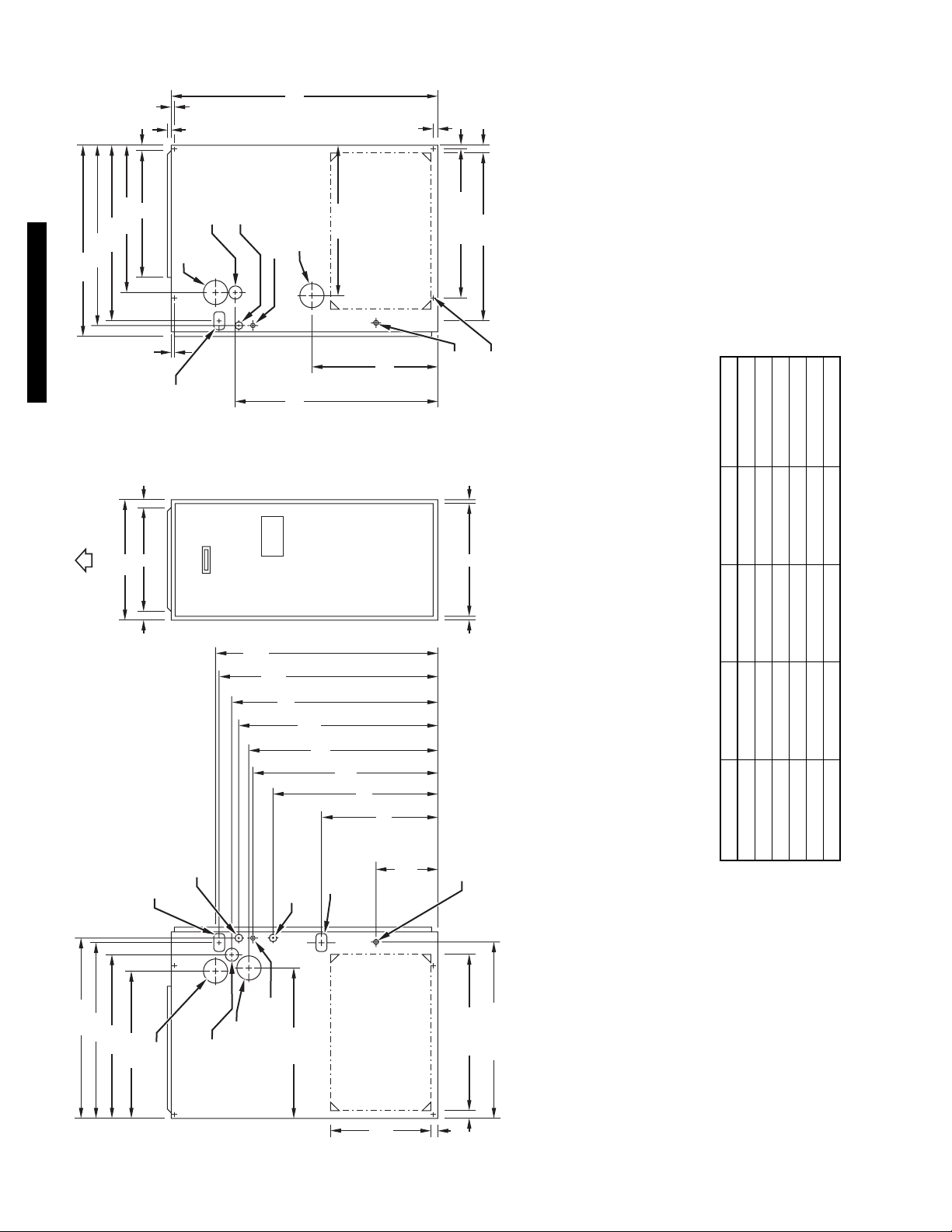
DIMENSIONS (In.)
return air openings for airflow requirements above 1800 CFM at 0.5” W.C. ESP.
combination of 1 side and the bottom, or the bottom only will ensure adequate
b. For 1200 CFM–20-in. round or 14
c. For 1600 CFM–22-in. round or 14
d. For airflow requirements above 1800 CFM, see Air Delivery table in Product Data
literature for specific use of single side inlets. The use of both side inlets, a
036060 17-1/2 15-7/8 16 189
048080 17-1/2 15-7/8 16 205
036080 17-1/2 15-7/8 16 200
UNIT SIZE A D E SHIP. WEIGHT (Lb)
048100 21 19-3/8 19-1/2 231
060100 21 19-3/8 19-1/2 234
060120 24-1/2 22-7/8 23 262
a. For 800 CFM–16-in. round or 14
"
16
⁄
5
17
"
16
⁄
7
TYP
9
CONDENSAT E
DRAIN LOCATION
(UPFLOW)
see flex duct manufacturerís recommendations for equivalent diameters.
2. Minimum return-air opening at furnace:
NOTES: 1. Minimum return-air openings at furnace, based on metal duct. If flex duct is used,
A05070
"
16
⁄
"
15
4
⁄
1
"
26
2
⁄
1
26
"
16
⁄
24
5
22
⁄2-IN. DIA
2-IN. COMBUSTION-
AIR CONN
1
GAS CONN
2-IN. VENT CONN
ENTRY
"
16
⁄
11
22
⁄2-IN. DIA THERMOSTAT
1
SIDE INLET
"
2
⁄
1
TYP
14
"
4
⁄
1
1
" TYP
4
⁄
1
23
SIDE INLET
1"
15
" TYP
16
⁄
26
times
times italic
times bold
—2—
Page 3
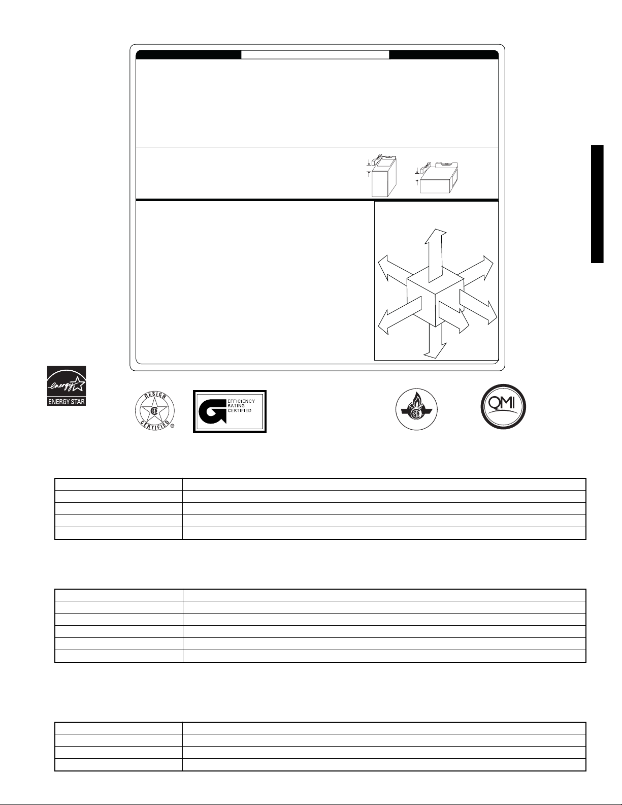
Clearance to Combustibles
This for ced air furnace i s equipped for us e with natural gas at altitudes 0 - 10,000 ft (0 - 3,050m), except 140 si ze Furnaces are only approved for altitudes 0 - 7,000 f t. (0 - 2,135m).
An accesso ry kit, supplied by the manuf acturer, shall be used to convert to propane gas use or may be required for some natural gas applic ations.
This f urnace is for indo or instal lation in a bui lding cons tructed on site. This fur nace may be i nstalled in a manuf actured (mob ile) home when stated on rati ng plate and using factory
authorized kit.
This f urnace may be install ed on combust ible fl ooring i n alcove or closet at minimum clearance f rom combustibl e materi al.
This appl iance r equires a special v enting syst em. Refer to the i nstallat ion ins tructions for par ts list and method of inst allati on. This furnace i s for us e with sch edule-40 PVC, PVC-DWV,
CPVC, or ABS-DWV pipe, and must not be vented in common wit h other gas-fire d appliances . Construc tion thr ough which vent/air intake pipes may be inst alled is maximum 24 inches
(600 mm), minimum 3/4 inches (19 mm) thickness (including roofing materials).
Cette fournaise à ai r pulsé est équipée pour util isation avec gaz naturel et altitudes comprises entre 0 - 3,050m
(0-10,000 pi), except é queles fournaises de 140 tail le sont pour altit udes comprises entre 0 - 2,135m (0 - 7,000 pi).
Utili ser une t rousse de co nversion, fournie par le f abricant, pour passer au gaz propane ou pour certai nes instal lations au gaz naturel.
Cette fournaise à ai r pulsé est pour inst allation à l´int érieur dans un bâtiment construit sur place. Cette fournaise à air pulsé peut être i nstallée dans une mai son préfabr iquée
(maison mobile) si prescri t par l a plaque si gnaléti que et si l´on ut ilise une trousse specifi ée par le fabricant .
Cette fournaise peut être installée sur un plancher combustible dans un enfoncement ou un placard en observant les dégagements minimums avec l es matériaux combustibl es.
Cet appareil nécessite un système d´évacuation spécial. La méthode d´inst allation et la l iste des pièces nécessaires fi gurent dans les instructi ons d´installation.Cett e fournaise doit
s´uti liser avec la tuy auterie des nomencl atures 40 PVC, PVC-DWV, CPVC, ou ABS-DWV et elle ne peut pas être venti lée conjointm ent avec d´autres appareil s à gaz. Épaisseur de la
construc tion au travers de laquelle il est possibl e de fair e passer l es tuyaux d´aérati on (admissi on/évacuati on): 24 po (600 mm) maximum, 3 /4 po (1 9 mm) mini mum (y comp ris l a toit ure).
For upflow and downflow applications, furnace must be installed level, or pitched within 1/2"
of level. For a horizontal applicat ion, the furnace must be pitched minimum 1/4" to
maximum of 1/2" forward for proper drai nage. See Installation Manual for IMPORTANT unit
support details on horizontal appli cations.
Pour des applications de f lux ascendant et descendant, la fournaise doit être install ée de
niveau ou inclinée à pas plus de 1/2" du niveau. Pour une application hori zontale, la
fournaise doit êtr e inclinée entre minimum 1/4" et maximum 1/2" du niveau pour le drainage
approprié. En cas d'i nstallation en position hor izontale, consulter les renseignements
IMPORTANTS sur le suppor t dans le manuel d'i nstallation.
MINIMUM INCHES CLEARANCE TO COMBUSTIBLE CONSTRUCTION
ALL POSITIONS:
Minimum front cl earance for servi ce 30 inches (762mm).
*
†
†
140 size furnaces requi re 1 inc h back clearanc e to combusti ble materials.
DOWNFLOW POSITIONS:
For inst allati on on combustible f loors only when installe d on special base No. KGASB0201ALL, Coil
†
Assembly, Part No. CD5 or CK5, or Coil Casing, Part No. KCAKC.
HORIZONTAL POSITIONS:
Line cont act is per missible onl y between li nes formed by i ntersections of top and two sides of furnace
jacket, and buil ding joists, studs, or framing.
Clearance shown is for air inlet and air outlet ends.
§
120 and 140 size furnaces requir e 1 inch bottom clearance to combustible material s.
Ø
DÉGAGEMENT MINIMUM EN POUCES AVEC ÉLÉMENTS DE CONSTRUCTION COMBUSTIBLES
POUR TOUS LES POSITIONS :
Dégagement avant minimum de 762mm (30 po) pour l´entreti en.
*
Pour les four naises de 140 taill e, 1 po (25mm) dégagement des matériau x combusti bl es est requis
†
†
au-arriere.
POUR LA POSITION COURANT DESCENDANT:
Pour l´instal lation sur le plancher combustible seul ement quand on uti lise la base spéciale, pi èce
†
n° KGASB0201ALL, l´ ensemble serpentin, pi èce n° CD5 ou CK5, ou le car ter de serpentin, pièce
n° KCAKC.
POUR LA POSITION HORIZONTALE:
Le contact n´est permis qúentre les lignes formées par les i ntersections du dessus et des deuxcôtés de la
chemi se de la f ournaise, et des soli ves, des montant s ou de la charpente du bátiment.
La distance indiquée concerne l´ extrémité du tuyau d´arrivée d´air et l´extrémité du tuyau de sorti e d´air.
§
Pour les four naises de 120 et 140 tail le, 1 po (25mm) dégagement des matéri aux combustibles est re quis
Ø
au-dessous.
INSTALLATION
LEVEL (0")
TO
1/2" MAX
UPFLOW OR
DOWNFLOW
R
324999-201 REV. D (LIT TOP)
MIN 1/4"
TO
1/2" MAX
FRONT
This furnace is approved f or UPFLOW, DOWNFLOW and
HORIZONTAL i nstall ations.
Cette fournaise est approuvée pour l´ins tallation HORIZONTALE
et l a circul ation d´ air VERS LE HAUT et VERS LE BAS.
Clearance arrows
do not change with
furnace orientati on.
†
†
0"
B
A
A
R
R
0"
§
Clearance in inches
Dégagement (po).
FRONT
C
K
I
E
R
E
E
D
S
I
S
E
T
O
C
HORIZONTAL
1"
Les fléches de dégagement
générateur d´air chaud.
TOP/PLENUM
DESSUS/CHA MBRE D´AI
E
C
E
A
S
I
N
A
R
U
N
F
R
T
U
N
O
O
F
T
R
N
F
A
V
A
F
R
O
A
N
V
T
A
N
T
3"
BOTTOM
DESSOUS
0"
Ø
†
d´évent avec combustibles.
ne change pas avec
l´ori entation de la
I
S
O
C
S
L
È
N
T
Vent clearance to
combustibles 0".
0 (po) Dégagement
352AAV
§
0"
E
D
S
E
T
E
R
V
I
R
C
E
E
T
I
E
*
N
30
MIN
A02148
ISO 9001:2000
MEETS DOE RESIDENTIAL
CONSERVATION SERVICES
As an ENERGY STAR
®
Partner, Bryant Heating &
Cooling Systems has determined that this product meets
the ENERGY STAR
®
guide-
lines for energy efficiency.
TSTATBBNAC01-C
TSTATBBNHP01-C*
TSTATBBN2S01-C*
TSTATBBBAC01-B
TSTATBBPRH01-B**
PROGRAM STANDARDS.
ama
Before purchasing this appliance,
read important energy cost and
efficiency information available
from your retailer.
CERTIFIED
®
REGISTERED QUALITY SYSTEM
These products are engineered and manufactured
under an ISO 9001 registered quality system.
Non-Programmable Thermostat Selection
For use with 1-spd. Air Conditioner - deg. F/C, Auto Changeover
For use with 1-spd. Air Conditioner - deg. F/C, Auto Changeover
For use with 2-spd. Air Conditioner - deg. F/C, Auto Changeover
For use with 1-spd. Air Conditioner - deg. F/C
For multi-use / stage configurations - deg. F/C, Auto Changeover/Temperature and Humidity Control
REGISTERED
* Model HP and 2S thermostat must be field converted to air conditioner operation.
**Thermidistat Control is versatile and can be configured for multiple use and staging, it must be configured for each specific application.
Programmable Thermostat Selection
TSTATBBPAC01-B
TSTATBBPHP01-B*
TSTATBBP2S01-B*
TSTATBBSAC01
TSTATBBPDF01-B**
TSTATBBPRH01-B***
* Model HP and 2S thermostat must be field converted to air conditioner operation.
**Dual Fuel thermostat is used with furnace and heat pump application
***Thermidistat Control can be configured for multiple use and staging, it must be configured for each specific application.
For use with 1-spd. Air Conditioner - deg. F/C, Auto Changeover, 7-Day Programmable
For use with 1-spd. Air Conditioner - deg. F/C, Auto Changeover, 7-Day Programmable
For use with 2-spd. Air Conditioner - deg. F/C, Auto Changeover, 7-Day Programmable
For use with 1-spd. Air Conditioner - deg. F/C, 5-2 Day Programmable
For use with multi-stage applications - deg. F/C, Auto Changeover, 7-Day Programmable
For multi-use / stage configurations - deg. F/C, Auto Changeover, 7-Day Programmable/Temperature and Humidity Control
ZONEBB3Z(AC/HP)01
ZONEBB2KIT01-B
ZONEBB4KIT01-B
ZONEBB8KIT01-B
Zoning Control Selection
Zone Perfect Two-Zone kit
Zone Perfect Plus 2-Zone kit/Temperature and Humidity Control
Zone Perfect Plus 4-Zone kit/Temperature and Humidity Control
Zone Perfect Plus 8-Zone kit/Temperature and Humidity Control
—3—
Page 4
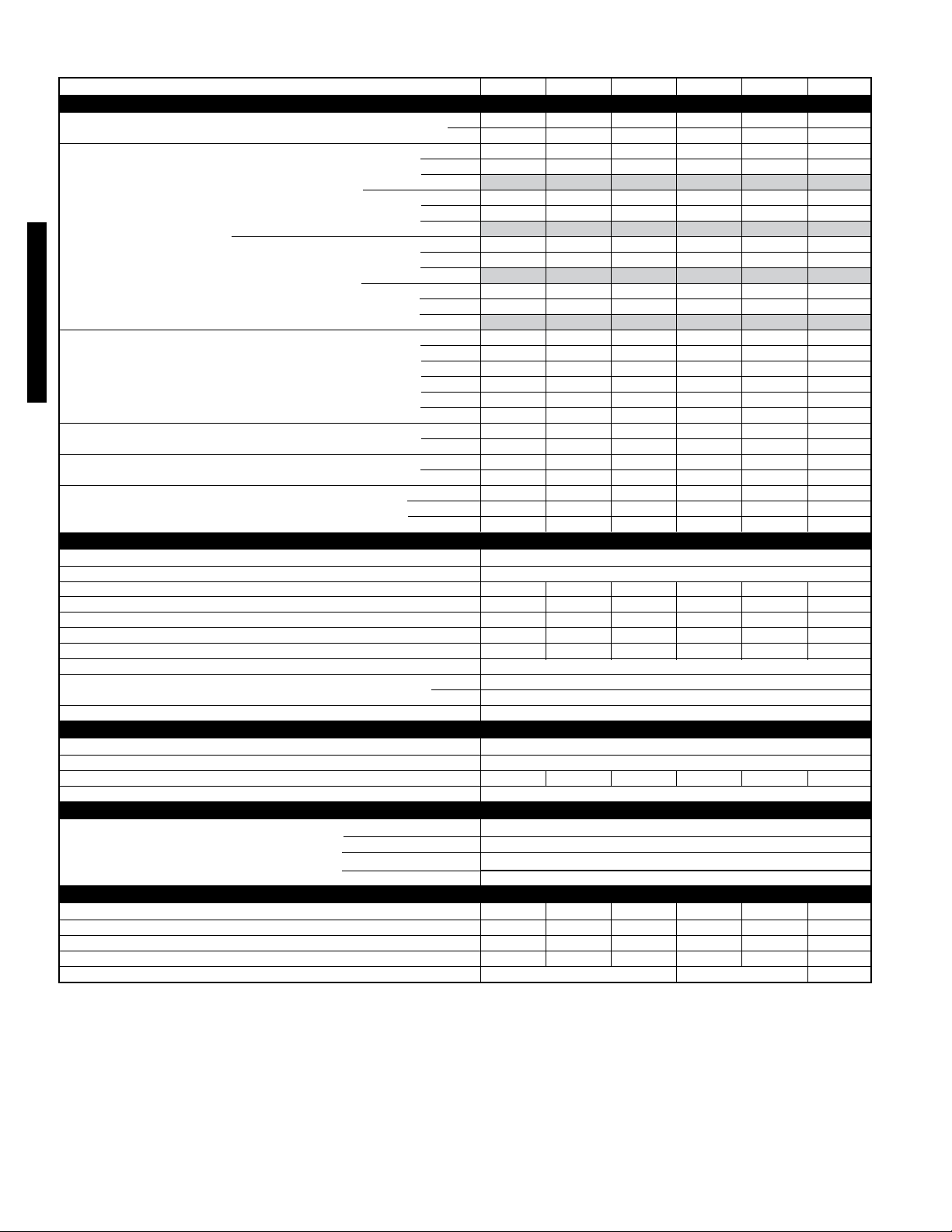
SPECIFICATIONS
UNIT SIZE 036060 036080 048080 048100 060100 060120
RATINGS AND PERFORMANCE
Input Btuh† Low 39,000 52,000 52,000 65,000 65,000 78,000
High 60,000 80,000 80,000 100,000 100,000 120,000
Output Capacity BTUH* (ICS) Direct Vent (2-Pipe) Low Upflow 37,000 49,000 49,000 61,000 61,000 74,000
(Shaded capacities are specified Downflow 37,000 49,000 49,000 61,000 61,000 74,000
on rating plate) Horizontal
High Upflow
Downflow 57,000 75,000 75,000 94,000 94,000 113,000
Non-Direct Vent (1-Pipe) Low Upflow 37,000 49,000 49,000 61,000 61,000 73,000
High Upflow 56,000 75,000 75,000 94,000 94,000 112,000
352AAV
AFUE† Direct Vent (2-Pipe) Upflow 93.0 93.0 93.0 93.0 93.0 93.0
Nonweatherized ICS
Non-Direct Vent (1-Pipe) Upflow 92.4 92.4 92.4 92.4 92.4 92.4
Certified Temperature Rise Range °F Low 20—50 30—60 30—60 25—55 30—60 30—60
Certified External Static Pressure (ESP)
(In. wc)
Airflow CFM‡ Heating Low 680 790 775 1175 1205 1215
ELECTRICAL
Unit Volts—Hertz—Phase 115—60—1
Operating Voltage Range Min-Max **
Maximum Unit Amps 8.4 8.1 11.6 11.6 13.3 12.9
Unit Ampacity†† 11.3 10.8 15.3 15.4 17.5 16.8
Minimum Wire Size 14 14 12 12 12 12
Maximum Wire Length (Ft)‡‡ 33 34 37 37 33 34
Maximum Fuse Size or Ckt Bkr Amps ††† 15 15 20 20 20 20
Transformer (24v) 40va
External Control Power Available Heating 19
Air Conditioning Blower Relay Standard
CONTROLS
Limit Control SPST
Heating Blower Control (Off Delay) Selectable 90, 120, 150, or 180 Seconds
Burners (Monoport) 344556
Gas Connection Size 1/2-in. NPT
GAS CONTROLS
2-Stage Redundant Gas Valve Manufacturer White-Rodgers
Min Inlet Pressure (In. wc) 4.5 (Natural Gas)
Max Inlet Pressure (In. wc) 13.6 (Natural Gas)
Ignition Device Hot Surface
BLOWER DATA
Direct-Drive Motor HP (Permanent Split Capacitor) 1/3 1/3 1/2 1/2 3/4 3/4
Motor Full Load Amps 5.1 5.1 7.4 7.9 11 11
RPM (Nominal)—Speeds 1075—5 1075—5 1075—5 1075—4 1075—5 1075—5
Blower Wheel Diameter x Width (In.) 10 7 10 7 11 8 11 8 11 10 11 10
Filter Size (In.)—Permanent Washable
Horizontal
Downflow 37,000 49,000 49,000 61,000 61,000 73,000
Horizontal
Downflow 56,000 75,000 75,000 94,000 94,000 112,000
Horizontal
Downflow 91.5 91.5 91.5 91.5 91.5 91.5
Horizontal 92.3 92.3 92.3 92.3 92.3 92.3
Downflow 91.4 91.4 91.4 91.4 91.4 91.4
Horizontal 91.4 91.4 91.4 91.4 91.4 91.4
High 30—60 40—70 30—60 45—75 30—60 40—70
Heating 0.12 0.15 0.15 0.2 0.2 0.2
Cooling 0.5 0.5 0.5 0.5 0.5 0.5
Heating High 1010 1130 1190 1315 1795 1770
Cooling 1275 1380 1565 1570 2035 2075
Cooling 35
See notes on page 5.
37,000 49,000 49,000 61,000 61,000 73,000
56,000 75,000 75,000 94,000 94,000 113,000
56,000 75,000 75,000 94,000 94,000 112,000
36,000 48,000 48,000 60,000 61,000 73,000
56,000 74,000 75,000 93,000 93,000 112,000
104—127
(1) 16 25 1 (1) 20 25 1 (1) 24 25 1
—4—
Page 5

*
SPECIFICATIONS Continued
FACTORY-AUTHORIZED AND LISTED DEALER-INSTALLED OPTIONS
Gas Conversion Kit—Natural-to-Propane KGANP4001ALL
Gas Conversion Kit—Propane-to-Natural KGAPN3301ALL
Twinning Kit KGATW0601HSI#
Downflow Base ***
Vent Termination Kit (Bracket Only for 2 Pipes) 2-in.—KGAVT0101BRA aaaa3-in.—KGAVT0201BRA
Concentric Vent Termination Kit (Single Exit) 2-in.—KGAVT0501CVT aaaa3-in.—KGAVT0601CVT
Condensate Freeze Protection Kit KGAHT0101CFP
Condensate Neutralizer Kit (Obtained Thru RCD) P908-0001
Electronic/Mechanical Air Cleaner Model EACB, EZXCAB or FILCAB
Humidifier Model HUM
Heat/Energy Recovery Ventilator Model HRV, ERV
Vent/Exhaust Pipe External Trap Kit KGAET0106ETK
UV Lights Model UVL
Door Gasket Kit KGBAC0110DGK
Gas input ratings are certified for elevations to 2000 ft. For elevations above 2000 ft, reduce ratings 2% for each 1000 ft above sea level. In Canada, derate
the unit 5% from 2000 to 4500 ft above sea level.
† Capacity and AFUE in accordance with U.S. Government DOE test procedures effective November 10, 1997.
‡ • Airflow shown is with factory-supplied 1-in. washable filter(s).
• For air delivery above 1800 CFM, see Air Delivery table for other options.
• An airflow reduction of up to 7% may occur when using the factory-specified 4 5/16-inch wide, high efficiency media filter.
• For best furnace efficiency when using the 4 5/16-inch wide media filter, adjust the blower speed tap to near the mid-point of the rise range.
**
Permissible voltage limits for proper furnace operation.
†† Unit ampacity = 125% of largest component’s full load amps plus 100% of all other potential operating components (EAC, humidifier, etc.).
‡‡ Length shown is measured 1 way along wire path between unit and service panel for maximum 2% voltage drop.
*** Required for installation on combustible floors when no coil box is used, or when any coil box other than a Bryant CD5 or CK5 cased coil is used.
N/A—Not applicable
ICS—Isolated Combustion System
#
For 048 and 060 airflow sizes only. See kit installation instructions for details.
KGASB0201ALL
352AAV
—5—
Page 6

ALTITUDE (FT)
0 to 2000
352AAV
ALTITUDE (FT)
2001 to 3000
ALTITUDE (FT)
3001 to 4000
See notesat end of table
COMBUSTION-AIR AND VENT PIPING FOR DIRECT VENT (2-PIPE)
AND NON-DIRECT VENT (1-PIPE) APPLICATIONS
MAXIMUM ALLOWABLE PIPE LENGTH (FT)
UNIT MAX
INPUT RATE
(BTUH)
60,000
80,000
100,000
120,000
UNIT MAX
INPUT RATE
(BTUH)
60,000
80,000
100,000
120,000
UNIT MAX
INPUT RATE
(BTUH)
60,000
80,000
100,000
120,000
DIRECT VENT (2-PIPE) ONLY
TERMINATION
TYPE
2 Pipe or 2-in
Concentric
2 Pipe or 2-in
Concentric
2 Pipe or 3-in
Concentric
2 Pipe or 3-in.
Concentric
DIRECT VENT (2-PIPE) ONLY
TERMINATION
TYPE
2 Pipe or 2-in
Concentric
2 Pipe or 2-in
Concentric
2 Pipe or 3-in
Concentric
2 Pipe or 3-in.
Concentric
DIRECT VENT (2-PIPE) ONLY
TERMINATION
TYPE
2 Pipe or 2-in
Concentric
2 Pipe or 2-in
Concentric
2 Pipe or 3-in
Concentric
2 Pipe or 3-in.
Concentric
4† no disk 4†nodisk 4†nodisk 707070707070
PIPE DIA
(IN.)*
1-1/2 1-1/2 20 15 10 5 NA NA
2 2 70 70 70 70 70 70
1-1/2 1-1/2 10 NA NA NA NA NA
22555035 30 3020
2-1/2 2-1/2 70 70 70 70 70 70
2 2 5 NANANANANA
2-1/2 2-1/2 40 30202010NA
3370 70 70 70 70 70
2-1/2 one disk 2-1/2 10 NA NA NA NA NA
3†NA454035 302520
3†nodisk 3† 707070707070
PIPE DIA
(IN.)*
1-1/2 1-1/2 17 12 7 NA NA NA
2 2 70 67 66 61 61 61
2 2 49 44 30252515
2-1/2 2-1/2 70 70 70 70 70 70
2-1/2 2-1/2 35261616 6NA
33
3 NA 14 9 NANANANA
NA 3†63 62 62 61 61 61
3†nodiskNA707063 56 50 43
4† no disk4†nodisk 707070707070
PIPE DIA
(IN)*
1-1/2 1-1/2 16 11 6 NA NA NA
226863 62 57 57 56
2 2 46 41 28 23 22 13
2-1/2 2-1/2 707070707070
2-1/2 2-1/2 33 24 15 14 5 NA
3370 70 70 66 61 56
3†nodisk NA 6558514438 31
NA 3† 595958575756
NON-DIRECT VENT
(1-PIPE) ONLY
PIPE DIA
(IN.)*
NON-DIRECT VENT
(1-PIPE) ONLY
PIPE DIA
(IN.)*
NON-DIRECT VENT
(1-PIPE) ONLY
PIPE DIA
(IN.)*
NUMBER OF 90° ELBOWS
12 3 4 56
NUMBER OF 90° ELBOWS
12 3 4 56
70 70 70 70 66 61
NUMBER OF 90° ELBOWS
12 3 4 56
—6—
Page 7

ALTITUDE (FT)
COMBUSTION-AIR AND VENT PIPING FOR DIRECT VENT (2-PIPE)
AND NON-DIRECT VENT (1-PIPE) APPLICATIONS continued
MAXIMUM ALLOWABLE PIPE LENGTH (FT) (CONTINUED)
UNIT MAX
INPUT RATE
(BTUH)
DIRECT VENT (2-PIPE) ONLY
TERMINATION
TYPE
PIPE DIA
(IN.)*
NON-DIRECT VENT
(1-PIPE) ONLY
PIPE DIA
(IN.)*
NUMBER OF 90° ELBOWS
12 3 4 5 6
4001 to 5000‡
ALTITUDE (FT)
5001 to 6000‡
ALTITUDE (FT)
60,000
80,000
100,000
120,000
UNIT MAX
INPUT RATE
(BTUH)
60,000
80,000
100,000
120,000
UNIT MAX
INPUT RATE
(BTUH)
2 Pipe or 2-in
Concentric
2 Pipe or 2-in
Concentric
2 Pipe or 3-in
Concentric
2Pipeor3-in.
Concentric
DIRECT VENT (2-PIPE) ONLY
TERMINATION
TYPE
2 Pipe or 2-in
Concentric
2 Pipe or 2-in
Concentric
2Pipeor3-in
Concentric
2Pipeor3-in.
Concentric
DIRECT VENT (2-PIPE) ONLY
TERMINATION
TYPE
1-1/2 1-1/2 15 10 5 NA NA NA
2 2 64 59 58 53 52 52
22443926212011
2-1/2 2-1/2 70 70 70 70 70 70
2-1/2 2-1/2 312213 12 NA NA
3370 70 67 62 57 52
3†nodiskNA53 46 40 33 26 20
NA 3†56555453 52 52
4† no disk 4†nodisk 707070707070
PIPE DIA
(IN.)*
1-1/2 1-1/2 14 9 NA NA NA NA
2 2 60 55 54 49 48 47
22413623 18 17 8
2-1/2 2-1/2 70 70 70 70 70 70
2-1/2 2-1/2 29 21 12 11 NA NA
3370 67 62 57 52 47
3†nodiskNA4235292215 9
NA 3†53 52 50 49 48 47
4† no disk4†nodisk 707070707070
PIPE DIA
(IN)*
NON-DIRECT VENT
(1-PIPE) ONLY
PIPE DIA
(IN.)*
NON-DIRECT VENT
(1-PIPE) ONLY
PIPE DIA
(IN)*
352AAV
NUMBER OF 90° ELBOWS
12 3 4 5 6
NUMBER OF 90° ELBOWS
12 3 4 5 6
6001 to 7000‡
See notesat end of table
60,000
80,000
100,000
120,000
2 Pipe or 2-in
Concentric
2Pipeor2-in
Concentric
2 Pipe or 3-in
Concentric
2Pipeor3-in.
Concentric
1-1/2 1-1/2 13 8 NANANANA
2 2 57 52 50 45 44 43
2238 33 21 16 15 6
2-1/2 2-1/2 70 70 68 67 66 64
2-1/2 2-1/2 27 19 10 9 NA NA
3368 63 58 53 48 43
3†nodiskNA312418 11NANA
NA 3† 494847454443
4† no disk4†nodisk 707070706762
—7—
Page 8

ALTITUDE (FT)
COMBUSTION-AIR AND VENT PIPING FOR DIRECT VENT (2-PIPE)
AND NON-DIRECT VENT (1-PIPE) APPLICATIONS continued
MAXIMUM ALLOWABLE PIPE LENGTH (FT) (CONTINUED)
NON-DIRECT VENT
(1-PIPE) ONLY
PIPE DIA
(IN.)*
NUMBER OF 90° ELBOWS
123456
UNIT SIZE
(BTUH)
DIRECT VENT (2-PIPE) ONLY
TERMINATION
TYPE
PIPE DIA
(IN.)*
7001 to 8000‡
352AAV
ALTITUDE (FT)
8001 to 9000‡
ALTITUDE (FT)
60,000
80,000
100,000
120,000
UNIT SIZE
(BTUH)
60,000
80,000
100,000
120,000
UNIT SIZE
(BTUH)
2 Pipe or 2-in
Concentric
2 Pipe or 2-in
Concentric
2 Pipe or 3-in
Concentric
2 Pipe or 3-in.
Concentric
DIRECT VENT (2-PIPE) ONLY
TERMINATION
TYPE
2 Pipe or 2-in
Concentric
2 Pipe or 2-in
Concentric
2 Pipe or 3-in
Concentric
2 Pipe or 3-in.
Concentric
DIRECT VENT (2-PIPE) ONLY
TERMINATION
TYPE
1-1/2 1-1/2 12 7 NANANANA
2253 48 46 41 40 38
2236 31191412NA
2-1/2 2-1/2 66 65 63 62 60 59
2-1/2 2-1/2 25 17 8 7 NA NA
3363 58 53 48 4338
3†nodiskNA2013 7NANANA
NA 3†464443 41 40 38
4† no disk4†nodisk615651464136
PIPE DIA
(IN.)*
1-1/2 1-1/2 11 6 NA NA NA NA
2 2 49 44 42 37 35 34
2233 28 17 12 10 NA
2-1/2 2-1/2 62 60 58 56 55 53
2-1/2 2-1/2 23 15 7 5 NA NA
3359 54 49 44 39 34
3†nodisk NA 10NANANANANA
NA 3†43 41 39 37 35 34
4† no disk4†nodisk 35 3025201510
PIPE DIA
(IN.)*
NON-DIRECT VENT
(1-PIPE) ONLY
PIPE DIA
(IN.)*
NON-DIRECT VENT
(1-PIPE) ONLY
PIPE DIA
(IN.)*
NUMBER OF 90° ELBOWS
123456
NUMBER OF 90° ELBOWS
123456
60,000
9001 to 10,000‡
*Disk usage-Unless otherwise specified, use perforated disk assembly (factory-supplied in loosepartsbag). If one diskisstated, separate 2 halves of perforated disk
assembly and use shouldered diskhalf. When using shouldered diskhalf, install screen side toward inlet box.
†Wide radius elbow.
‡Vent sizing for Ca
NA-Not Allowed; pressure switch will not make.
NOTES:
1. Do not use pipe size greater thanthose specified in table or incomplete combustion, flame disturbance, or flame senselockoutmay occur.
2. Size both the combustion-air and vent pipe independently, then usethel
3.Assume two 45° elbows equal one 90° elbow.Wideradius elbowsare desirable and may berequired in some cases.
4. Elbowsand pipe sections within the furnace casing and at the vent termination should not beincluded in vent length or elbow count.
5. The minimum pipe length is 5ftforall a pplications.
6. Use 3-in. diameter vent termination kit for in
nadianinstallations over 4500 ft (1370 m) above sea level are subject to acceptance bythelocal authorities having jurisdiction.
80,000
100,000
120,000
2 Pipe or 2-in
Concentric
2 Pipe or 2-in
Concentric
2 Pipe or 3-in
Concentric
2 Pipe or 3
Concentric
stallations requiring 4-in diameter pipe.
-in.
22454038 33 3129
22302514 9 7 NA
2-1/2 2-1/2 57 55 53 51 49 47
2-1/2 2-1/2 21 13 5NANANA
3354 49 44 39 3429
NA 3† 39 37 35 33 3129
4† no disk 4†nodisk 10 5 NANANANA
arger diameter for both pipes.
—8—
Page 9

MAXIMUM ALLOWABLE EXPOSED VENT PIPE LENGTH (FT) WITH AND WITHOUT INSULATION
IN WINTER DESIGN TEMPERATURE AMBIENT *
WINTER DESIGN
UNIT SIZE
060
080
100
120
TEMPERATURE
(°F)
20 2 44 70
0 2 21 70
–20 2 20 57
20 2 55 55
0 2 30 55
–20 2 16 55
20 2.5 58 70
0 2.5 29 70
–20 2.5 14 67
20 2.5 40 40
0 2.5 38 40
–20 2.5 21 40
20 3 63 70
0 3 30 70
–20 3 12 70
20 3 70 70
0338 70
–20 3 19 70
20 4 65 70
0 4 26 70
–20 4 5 65
* Pipe length (ft) specified for maximum pipe lengths located in unconditioned spaces. Pipes located in unconditioned space cannot exceed total
allowable pipe length as specified in Table 6.
† Insulation thickness based on R value of 3.5 per inch.
MAX PIPE
DIAMETER
(IN.)
WITHOUT
INSULATION
WITH 3/8-IN. OR
THICKER INSULATION†
352AAV
—9—
Page 10

CONDENSATE TRAP
352AAV
BLOWER SHELF
CONDENSATE
TRAP (INSIDE)
ALTERNATE DRAIN
TUBE LOCATION
CONDENSATE TRAP
DRAIN TUBE LOCATION
UPFLOW APPLICATIONS
FURNACE
DOOR
FIELD
DRAIN
CONN
EXTERNAL UPFLOW APPLICATIONS
SLOT FOR SCREW
HORIZONTAL
APPLICATION
(OPTIONAL)
1
1
2
3
4
WIRE TIE
GUIDES
(WHEN USED)
CONDENSATE
TRAP
FURNACE
SIDE
7
4
8
FURNACE
DOOR
4
FURNACE
SIDE
3
5
4
3
5
4
1
26
1
26
4
1
1
2
FIELD
DRAIN
CONN
4
3
4
SIDE VIEW FRONT VIEW END VIEW FRONT VIEW
DOWNFLOW AND ALTERNATE
1
7
8
3
1
4
7
8
1
2
4
1
⁄4 OD
COLLECTOR BOX TO
TRAP RELIEF PORT
1
⁄2 OD
INDUCER HOUSING
DRAIN CONNECTION
5
⁄8 OD
COLLECTOR BOX
DRAIN CONNECTION
SCREW HOLE FOR
UPFLOW OR DOWNFLOW APPLICATIONS
(OPTIONAL)
1
⁄2-IN. PVC OR CPVC
HORIZONTAL
APPLICATIONS
4
FRONT VIEW SIDE VIEW
A93026
—10—
Page 11

LENGTH OF STRAIGHT
PIPE PORTION OF COMBUSTION
AIR INLET PIPE ASSEMBLY (IN.)
CASING WIDTH A
17-1/2 8-1/2 ± 1/2
21 10-1/2 ± 1/2
24-1/2 12 ± 1/2
*
*
ACCESSORIES
COMBUSTION-AIR PIPE FOR NON-DIRECT VENT (1-PIPE) APPLICATION (SIZES 040 THROUGH 120 ONLY)
FIELD-SUPPLIED
CONCENTRIC VENT FOR DIRECT VENT (2-PIPE) APPLICATION (ALL MODEL SIZES)
NOTE:
See furnace
Installation Instruction
when venting multiple
furnaces near each other.
2-IN. DIAMETER
PVC 90° ELBOW
COMBUSTION-AIR DISC
(FACTORY-SUPPLIED IN
LOOSE PARTS BAG)
FIELD-SUPPLIED
2-IN. DIAMETER
PVC PIPE
A
A96211
B IN. DIA PVC
VENT/EXHAUST
1
/2
1
C IN. DIA
13/
16
D
A
B IN. DIA PVC
INTAKE/COMBUSTION AIR
A97110
F
E
352AAV
KGAVT0501CVT 33-3/8 2 3-1/2 16-5/8 6-1/4 5-3/4
KGAVT0601CVT 38-7/8 3 4-1/2 21-1/8 7-3/8 6-1/2
Dimension A will change accordingly as dimension D is lengthened or shortened.
†Dimension D may be lengthened to 60 in. maximum. Dimension D may also be shortened by
cutting the pipes provided in the kit to 12 in. minimum.
LOCATING
TAB
B
LOCATING
TAB
D
FURNACE
CASING
WIDTH FURNACE IN DOWNFLOW APPLICATION
17-1/2
21
24-1/2
The plenum should be constructed 1/4 in. smaller in width and depth than the plenum dimensions shown above.
Furnace with or without Cased Coil
Assembly or KCAKC Coil Box
Furnace with or without Cased Coil
Assembly or KCAKC Coil Box
Furnace with or without Cased Coil
Assembly or KCAKC Coil Box
DIMENSIONS (In.)
PART NO. A *
B C D† E F
ACCESSORY DOWNFLOW SUBBASE
4
3
2
1
FACTORY-SUPPLIED
4
2
3
A88207
1
FIELD-INSTALLED
INSULATION
PLENUM OPENING * FLOOR OPENING HOLE NO.
15-1/8 19 16-3/4 20-3/8 3
18-5/8 19 20-1/4 20-3/8 2
22-1/8 19 23-3/4 20-3/8 1
—11—
1 1/
″
TYP
4
PLENUM
OPENING
A
C
A97427
FOR WIDTH
ADJUSTMENTABCD
Page 12

MEDIA FILTER CABINET
5
/
25
8
5
/
23
8
"
3
/
8
"
23
Opening with Flanges Bent
3
24
1
23
Opening
"
/
8
"
/
8
"
352AAV
Furnace Side
3
/
4
"
23
Centerline Screw Slots
A
Duct Side
3
/
4
"
5
Media
Filter Cabinet
16" 17" 16"
20" 21" 20"
24" 25" 24"
AB
Shipped with sizes
024040, 036040, 024060, 036060,
048060, 036080, 048080
060080, 048100, 060100
gninepO B
060120, 060140
A05218
AIR DELIVERY—CFM (With Filter)
UNIT SIZE
BRYANT
RETURN-AIR
SUPPLY SPEED
0.1 0.2 0.3 0.4 0.5 0.6 0.7 0.8
High 1490 1450 1400 1345 1275 1190 1080 960
Med-High 1190 1180 1155 1120 1070 1005 915 810
Med 1015 1010 995 965 920 875 800 715
Med-Low 870 860 840 820 780 735 670 580
036060
1 side
or
bottom
Low 685 670 645 620 595 545 495 420
High 1605 1560 1510 1450 1380 1300 1195 1045
036080
1 side
or
bottom
Med-High 1305 1290 1265 1225 1175 1100 995 895
Med 1135 1125 1110 1080 1030 965 885 800
Med-Low 990 980 965 930 880 825 760 685
Low 805 780 745 700 660 630 575 495
High 1810 1755 1690 1640 1565 1495 1410 1330
048080
1 side
or
bottom
Med-High 1420 1385 1350 1305 1260 1210 1145 1090
Med 1205 1175 1135 1100 1060 1010 960 905
Med-Low 1035 990 945 910 875 840 790 735
Low 805 750 705 660 620 585 540 490
High 1740 1705 1660 1615 1570 1500 1425 1355
Med-High 1500 1470 1445 1410 1375 1330 1280 1210
Med-Low 1340 1315 1300 1270 1235 1200 1140 1095
Low 1195 1175 1165 1130 1100 1070 1030 975
04810
1 side
or
bottom
High 2345 2265 2195 2110 2035 1940 1850 1745
Med-High 2110 2065 2010 1945 1875 1800 1710 1615
Med 1810 1795 1770 1725 1680 1615 1545 1460
Med-Low 1480 1465 1440 1415 1375 1330 1260 1190
Low 1235 1205 1180 1155 1115 1065 1015 950
High 2425 2365 2300 2240 2160 208019801880
Med-High 2045 2025 2000 1965 1910 1850 1785 1695
High 2305 2235 2170 2100 2005 1925 1825 1730
Med-High 2030 1995 1950 1905 1835 1775 1685 1600
060100
bottom
only
both sides or
1 side and bottom
1 side only
High 2385 2320 2245 2160 2075 1975 1870 1775
Med-High 2105 2060 2005 1945 1880 1795 1710 1620
Med 1785 1770 1740 1700 1650 1600 1525 1450
Med-Low 1495 1470 1450 1420 1385 1335 1280 1220
Low 1250 1215 1190 1155 1125 1085 1040 985
High 2475 2435 2385 2320 2260 2180 2095 1995
Med-High 2085 2075 2055 2030 1980 1930 1865 1785
High 2255 2190 2115 2045 1965 1890 1800 1710
Med-High 1985 1930 1890 1840 1780 1720 1645 1560
060120
bottom
only
both sides or
1 side and bottom
1 side only
• Airflow shown is with factory supplied 1-in. washable filter.
• A filter is required for each return air opening.
• An airflow reduction of up to 7% may occur when using the factory-specified 4-5/16-inch wide, high efficiency media filter.
• For best furnace efficiency when using the 4 5/16-inch wide media filter, adjust blower speed tap to near the mid-point of the rise range.
• For horizontal and downflow applications, use 1 side or bottom or bottom only as an airflow reference.
EXTERNAL STATIC PRESSURE (In. wc)
—12—
Page 13

OUTDOOR UNIT
COMBUSTION
AIR INLET
(NON-DIRECT
1-PIPE APPLICATION)
COMBUSTION AIR PIPE
(DIRECT VENT/2-PIPE APPLICATION)
A/C COIL
ELECTRONIC
AIR CLEANER
VENT PIPE
HUMIDIFIER
GAS-FIRED
WATER HEATER
352AAV
AIRFLOW
ELECTRONIC
AIR CLEANER
COMBUSTION AIR
INLET (NON-DIRECT
VENT/ 1-PIPE APPLICATION
HUMIDIFIER
FRONT OF
FURNACE
A05064
VENT
COMBUSTION
AIR (DIRECT VENT/
2 PIPE APPLICATION
OUTDOOR
UNIT
A/C COIL
FRONT OF
AIRFLOW
FURNACE
A05065
—13—
Page 14

COMBUSTION-AIR INLET
(NON-DIRECT VENT/1-PIPE APPLICATION)
352AAV
ELECTRONIC
AIR CLEANER
FRONT OF FURNACE
AIRFLOW
VENT PIPE
FURNACE
CONDENSATE
DRAIN
REFRIGERATION
COMBUSTION–AIR PIPE
DIRECT VENT/2-PIPE APPLICATION)
AIR CONDITIONING
COIL
PIPING
A05066
COMBUSTION - AIR INLET
(NON-DIRECT VENT/
1-PIPE APPLICATION)
REFRIGERATION
PIPING
AIR CONDITIONING
COIL
AIRFLOW
FURNACE CONDENSATE
DRAIN
FRONT OF
FURNACE
COMBUSTION– AIR PIPE
(DIRECT VENT/2-PIPE
APPLICATION)
VENT
PIPE
ELECTRONIC
AIR CLEANER
A05067
—14—
Page 15

352AAV
—15—
Page 16

GUIDE SPECIFICATIONS
GENERAL
System Description
Furnish a _________________ (4-way multipoise) dual capacity gas-fired condensing furnace for use with natural gas or propane (factory authorized conversion kit required for propane);
furnish cold air return plenum; furnish external medial cabinet for
use with accessory media filter or standard filter.
Quality Assurance
Unit will be designed, tested and constructed to the current ANSI
Z 21.47/CSA 2.3 design standard for gas-fired central furnaces.
Unit will be 3rd party certified by CSA to the current ANSI Z
21.47/CSA 2.3 design standard for gas-fired central furnaces.
Unit will carry the CSA Blue Star® and Blue Flame® labels.
Unit efficiency testing will be performed per the current DOE test
procedure as listed in the Federal Register.
Unit will be certified for capacity and efficiency and listed in the
latest GAMA Consumer's Directory of Certified Efficiency
Ratings.
Unit will carry the current Federal Trade Commission Energy
Guide efficiency label.
Delivery, Storage, and Handling
Unit will be shipped as single package only and is stored and
handled per unit manufacturer's recommendations.
Warranty (for inclusion by specifying engineer)
U.S. and Canada only. Warranty certificate available upon
request.
PRODUCTS
Equipment
Components shall include: slow-opening dual rate gas valve to
reduce ignition noise, regulate gas flow, with electric switch gas
shut-off; flame proving sensor, hot surface igniter, pressure
switch assembly verifies inducer operation; flame rollout switch,
drain tubing and installed condensate drain trap, blower and inducer assembly, 40va transformer; low-voltage (heating) (heating/cooling) thermostat.
Blower Wheel and Blower Motor
Galvanized blower wheel shall be centrifugal type, statically and
dynamically balanced. Blower motor of PSC type shall be permanently lubricated with sealed bearings, of _____ hp, and shall
be multiple-speed direct drive. Blower motor shall be soft mounted to the blower scroll to reduce vibration transmission.
Filters
Furnace shall have reusable-type filters. Filter shall be ______ in
(x) ______in. An accessory high efficiency Media Filter is available as an option _____________Media Filter.
Casing
Casing shall be of .030 in. thickness minimum, pre-painted galvanized steel.
Two Speed Inducer Motor
Two Speed Inducer motor shall be soft mounted to reduce vibration transmission.
Primary Heat Exchangers
Primary Heat exchangers shall be 3-Pass 20 gauge corrosion
resistant aluminized steel of fold-and-crimp sectional design,
which operates under negative pressure.
Secondary Heat Exchangers
Secondary Heat exchangers shall be of a flow-through design
having a patented interior laminate coating of polypropylene for
greater corrosion resistance with fold-and-crimp design, which
operates under negative pressure.
Controls
Controls shall include a microprocessor based integrated electronic control board with at least 11 service troubleshooting
codes displayed via diagnostic flashing LED light on the control,
has ability to store fault codes, when activated a self-test feature
checks all major functions of the furnace within one minute, and
a replaceable automotive-type circuit protection fuse. Multiple
operational settings available including, separate blower speeds
for low heat, high heat, low cooling, high cooling and continuous
fan. Continuous fan speed may be adjusted from the thermostat.
Cooling airflow will be selectable between 350 or 400 CFM per
ton of air conditioning. Features will also include temporary reduced airflow in the cooling mode for improved dehumidification
when a Thermidistat® is selected as the thermostat.
Operating Characteristics
Heating Capacity shall be _________ Btuh input;
____________ Btuh output capacity.
Fuel Gas Efficiency shall be 93% AFUE.
Air delivery shall be __________ cfm minimum at 0.50 in. wg.
external static pressure.
Dimensions shall be: depth __________ in.; width __________
in.; height _________ in. (casing only). Height shall be
__________ in. with A/C coil and ____________ in. overall with
plenum.
Electrical Requirements
Electrical supply shall be 115 volts, 60 Hz, single-phase (nominal). Minimum wire size shall be _________ AWG; maximum
fuse size or HACR-type, designated circuit breaker shall be
_______ Amps.
Special Features
Refer to section of the product data s
sories and descriptions for specific features and available
enhancements.
heet identifying acces-
©Bryant Heating & Cooling systems 7310 W. Morris St. Indianapolis, IN 46231 Printed in U.S.A. edition date: 09/09 Catalog No. PDS 352A.60.2
352a.60.1 Rev.A SDP :secalpeRsnoitagilbo dna eciton tuohtiw sngised ro snoitacificeps ,emit yna ta ,egnahc ot thgir eht sevreser rerutcafunaM
—16—
 Loading...