

Bryant 349HAV Series, 349HAV036050, 349HAV036075, 349HAV048075, 349HAV048100 Installation, Start-up, And Operating Instructions Manual
...
installation, start-up,
and operating instructions
HORIZONTAL INDUCED-COMBUSTION
GAS FURNACE
SIZES 050—125, SERIES B
NOTE: Read the entire instruction manual before starting the
installation.
This symbol → indicates a change since the last issue.
INDEX
Page
SAFETY CONSIDERATIONS ................................................1-2
Clearances From Combustible Materials.................................1
INTRODUCTION.......................................................................2-3
Dimensional Drawing...............................................................2
LOCATION....................................................................................3
General......................................................................................3
Furnace Location Relative to Cooling Equipment..................3
Hazardous Locations.................................................................3
AIR FOR COMBUSTION AND VENTILATION...................3-5
General...................................................................................3-4
Unconfined Space.....................................................................4
Confined Space......................................................................4-5
Contaminated Combustion Air.................................................5
INSTALLATION........................................................................5-9
Duct Work Recommendations..................................................5
Horizontal Attic Installation.....................................................6
Horizontal Crawlspace Installation ..........................................6
Filter Arrangement....................................................................6
Gas Piping..............................................................................6-7
Reversing Procedure..............................................................7-9
ELECTRICAL CONNECTIONS.............................................9-11
115-v Wiring........................................................................9-11
Wiring Diagram......................................................................10
24-v Wiring.............................................................................11
Accessories..............................................................................11
VENTING...............................................................................11-13
General Venting Requirements.........................................11-12
Pre-Installation Vent System Inspection................................12
Removal of Existing Furnace from Common
Venting System..................................................................12
Metal Vent Installations..........................................................12
Masonry Chimney Installations..............................................12
Multistory Installations...........................................................12
Sidewall Venting Installations................................................12
SEQUENCE OF OPERATION...................................................13
Heating Mode..........................................................................13
Cooling Mode .........................................................................13
START-UP, ADJUSTMENT, AND SAFETY CHECK.......13-18
General....................................................................................13
Remove Shipping Bracket......................................................13
Purge Gas Lines......................................................................13
Operational Checkout .............................................................13
Adjustments .......................................................................14-17
Adjust Pilot Flame..................................................................14
Set Gas Input Rate ............................................................14-17
Set Temperature Rise..............................................................17
Set Blower Off Delay.............................................................17
Set Thermostat Heat Anticipator............................................17
Check Safety Controls.......................................................17-18
CHECKLIST................................................................................18
349HAV
Cancels: II 349H-50-4 II 349H-50-5
®
SAFETY CONSIDERATIONS
Installing and servicing heating equipment can be hazardous due to
gas and electrical components. Only trained and qualified personnel should install, repair, or service heating equipment.
Untrained personnel can perform basic maintenance functions
such as cleaning and replacing air filters. All other operations must
be performed by trained service personnel. When working on
heating equipment, observe precautions in the literature, on tags,
and on labels attached to or shipped with the unit and other safety
precautions that may apply.
TABLE 1—ATTIC, CLOSET*, OR ALCOVE CLEARANCES
FROM COMBUSTIBLE MATERIALS (IN.)
UNIT SIZE 050, 075, 100, & 125
Sides 6
Back 6
Top of Plenum 2
Vent Connector 6
Front Casing 6†
Front Service 30
* For closet installations, refer to Air for Combustion and Ventilation section.
† Measured from end of inducer motor.
WARNING: Failure to comply with all of the above
clearances will create a fire hazard.
→
Follow all safety codes. In the United States, follow all safety
codes including the National Fuel Gas Code (NFGC) NFPA No.
54-1996/ANSI Z223.1-1996 and the Installation Standards, Warm
Air Heating and Air Conditioning Systems (NFPA 90B)
ANSI/NFPA 90B. In Canada, refer to the current edition of the
National Standard of Canada CAN/CGA-B149.1- and .2-M95
Natural Gas and Propane Installation Codes (NSCNGPIC). Wear
safety glasses and work gloves. Have fire extinguisher available
during start-up and adjustment procedures and service calls.
Recognize safety information. This is the safety-alert symbol
When you see this symbol on the furnace and in instructions or
manuals, be alert to the potential for personal injury.
Understand the signal words DANGER, WARNING, and CAUTION. These words are used with the safety-alert symbol. DANGER identifies the most serious hazards which will result in severe
personal injury or death. WARNING signifies a hazard which
could result in personal injury or death. CAUTION is used to
identify unsafe practices which would result in minor personal
injury or product and property damage.
ama
CANADIAN GAS ASSOCIATION
APPROVED
R
6-98
.
—1—
These instructions cover minimum requirements and conform to
existing national standards and safety codes. In some instances,
these instructions exceed certain local codes and ordinances,
especially those that may not have kept up with changing residential construction practices. We require these instructions as a
minimum for a safe installation.
INTRODUCTION
The design of the 349HAV Horizontal Induced-Combustion Gas
Furnace is A.G.A./C.G.A. certified as a Category I furnace for
natural and propane gases and for installation in alcoves, basements, crawlspaces, utility rooms, and attics. The design of the
horizontal gas-fired furnace is A.G.A./C.G.A. certified for installation on noncombustible floors. This furnace may be installed on
combustible wood flooring, however, it may not be installed
directly on carpeting, tile, or other combustible material other than
wood. The design of this furnace line is not A.G.A. certified for
installation in recreational vehicles, manufactured housing (mobile
homes), or outdoors.
The furnace is shipped as a packaged unit, complete with burners
and controls, and requires a 115-v line voltage connection to
junction box, a thermostat hook-up as shown in the wiring
diagram, and a gas line connection. The furnace is shipped in the
horizontal left configuration (for right-to-left airflow) but is easily
converted to the horizontal right configuration (for left-to-right
airflow). Refer to Reversing Procedure section for details.
The furnace is designed to interface with split system cooling
equipment (approved by UL) to provide year-round air conditioning. The blower is sized for both heating and cooling, and the
furnace control includes a cooling fan relay.
Before installing the furnace, refer to the current edition of the
NFGC and the NFPA 90B. Canadian installations must be installed
in accordance NSCNGPIC and all authorities having jurisdiction.
For a copy of the NFGC NFPA54/Z223.1, contact International
Approval Services U.S. Inc., 8501 E. Pleasant Valley Road,
Cleveland, OH 44131 or National Fire Protection Association Inc.,
Batterymarch Park, Quincy, MA 02269. For a copy of NFPA 90B,
contact National Fire Protection Association Inc., Batterymarch
Park, Quincy, MA 02269.
Before installing furnace in Canada, refer to the current edition of
the NSCNGPIC. Contact Standards Department of Canadian Gas
Association, 55 Scarsdale Road, Don Mills, Ontario, Canada M3B
2R3. Canadian installations must be made in accordance with
CAN/CGA-B149 Installation Codes and authorities having jurisdiction.
→
Installations must comply with the regulations of the serving gas
supplier and the local building, heating, plumbing, or other codes
in effect in the area in which the installation is made. In the
absence of local codes, the installation must conform with the
NFGC, NFPA No. 54-1996/ANSI Z223.1-1996.
CAUTION: Application of this furnace should be indoors with special attention given to vent sizing and
material, gas input rate, air temperature rise, and unit
sizing. Improper installation or misapplication of the
furnace can require excessive servicing or cause premature component failure.
(EXTEND BLOWER DOOR)
5
⁄8″
D ( NUMBER OF CELLS)
3 1⁄2″
1 3⁄4″
T-STAT
CONNECTION
1
⁄2-IN. GAS CONNECTION
A
19 1⁄2″
5
⁄16″
B
7
5 5⁄8″
(HIGH AIR FLOW UNITS ONLY)
2 1⁄2″
10″
⁄8″
26 5⁄8″
19 1⁄4″
7″
(2 PLACES)
7
⁄8-IN. ELECTRICAL
CONNECTION
28 7⁄8″
50″
C
4-IN. DIA VENT
CONNECTION
18″
5
4 9⁄16″
6 5⁄16″
4 1⁄8″
⁄8″
1 7⁄8″
5
⁄16″
B
21 3⁄8″
23 1⁄8″
7
⁄8″
A
AIR FLOW
5 7⁄8″
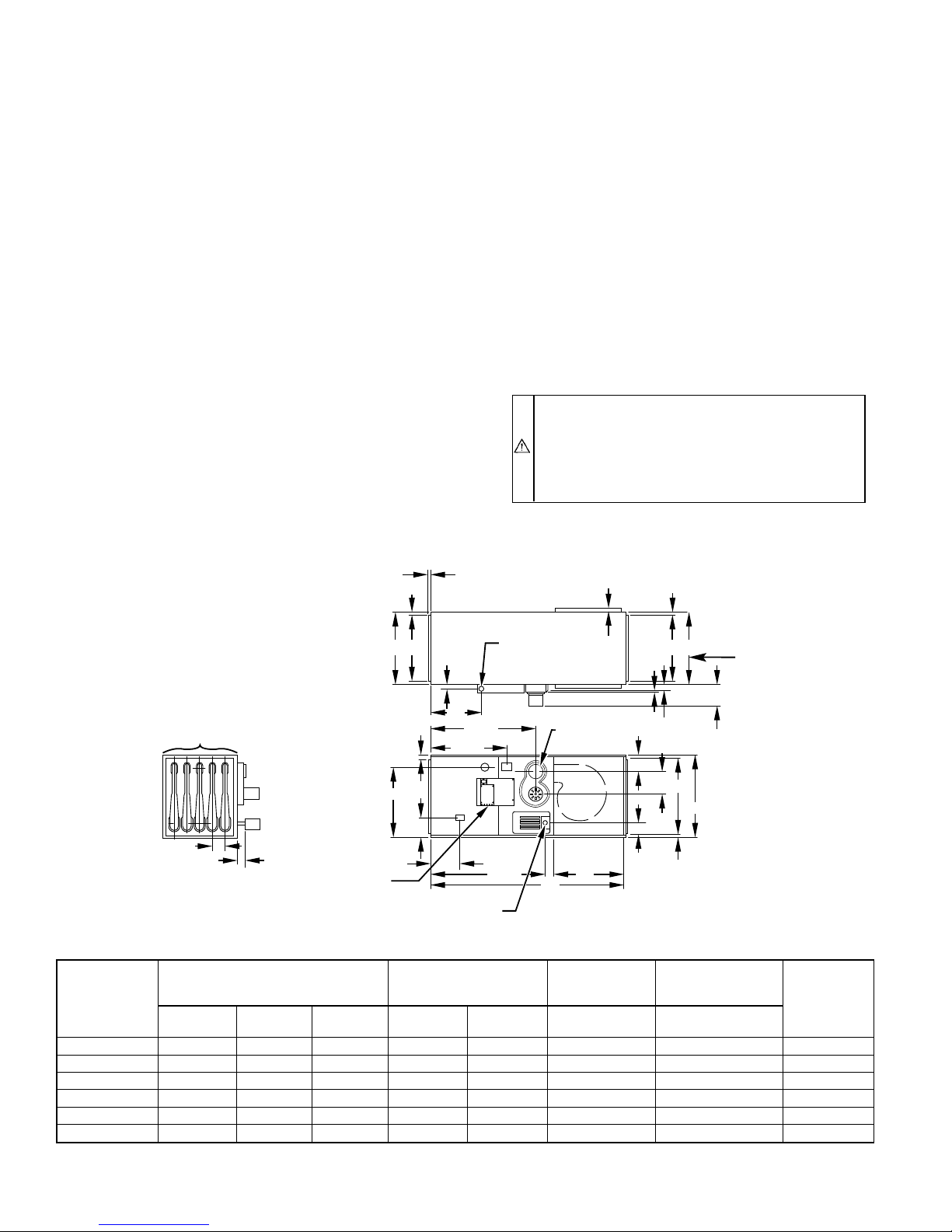
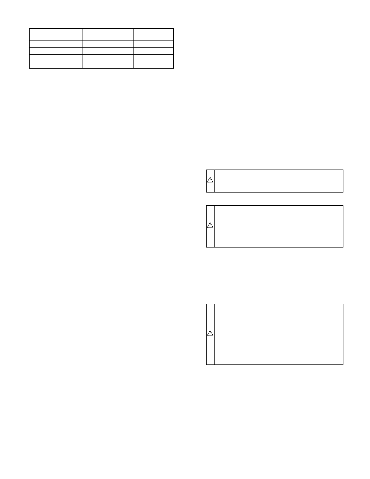
DIMENSIONS (IN.)
UNIT DIMENSIONS
UNIT SIZE
Length
036050 50 13-1/2 23-1/8 11-5/8 21-3/8 Flush 2 112
036075 50 13-1/2 23-1/8 11-5/8 21-3/8 Flush 3 121
048075 50 13-1/2 23-1/8 11-5/8 21-3/8 1 3 125
048100 50 17 23-1/8 15-1/8 21-3/8 Flush 4 141
060100 50 17 23-1/8 15-1/8 21-3/8 1 4 149
060125 50 20-1/2 23-1/8 18-5/8 21-3/8 Flush 5 161
* High airflow units only.
Width
A
Height
DUCT SUPPLY
AND RETURN
OPENINGS
Width
B
Height C D
EXTENDED
BLOWER
DOOR*
NUMBER
OF HEAT
EXCHANGERS
Fig. 1—Dimensional Drawing
A96068
NET
WEIGHT
(LB)
—2—
This furnace is designed for a minimum continuous return-air
temperature of 60°F db or intermittent operation down to 55°F db
such as when used with a night setback thermostat. Return-air
temperature must not exceed a maximum of 85°F db.
WARNING: Improper installation, adjustment, alter-
ation, service, maintenance, or use can cause carbon
monoxide poisoning, explosion, fire, electrical shock, or
other conditions which may cause personal injury or
property damage. Consult a qualified installer, service
agency, local gas supplier, your distributor, or your
branch for information or assistance. The qualified in-
staller or agency must use only factory-authorized and
listed kits or accessories when modifying this product.
Failure to follow this warning could result in electrical
shock, fire, personal injury, or death.
Locate furnace where available electrical and gas supplies meet the
specifications on furnace rating plate.
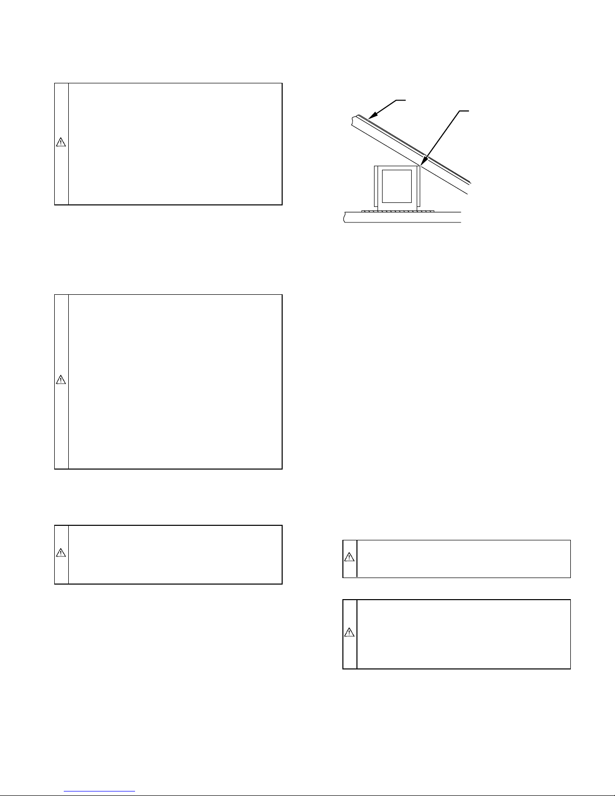
Line contact is only permissible between lines formed by the
intersection of furnace top and front and back sides and building
joists, studs, or framing. (See Fig. 2.)
ROOF
LINE CONTACT ONLY
PERMISSIBLE BETWEEN
TOP CORNERS OF
FURNACE AND BUILDING
JOISTS, STUDS, OR
FRAMING.
For accessory installation details, refer to the applicable installation literature.
NOTE: Remove all shipping brackets and materials before operating furnace.
LOCATION
I. GENERAL
CAUTION: Do not install furnace in a corrosive or
contaminated atmosphere. Make sure all combustion and
circulating air requirements are followed, in addition to
all local codes and ordinances.
Do not use this furnace during construction when adhe-
sives, sealers, and/or new carpets are being installed. If
the furnace is required during construction, use clean
outside air for combustion and ventilation. Compounds of
chlorine and fluorine when burned with combustion air
form acids which cause corrosion of the heat exchangers
and metal vent system. Some of these compounds are
found in paneling and dry wall adhesives, paints, thin-
ners, masonry cleaning materials, and many other sol-
vents commonly used in the construction process. Exces-
sive exposure to contaminated combustion air will result
in safety and performance related problems.
This furnace may be located in an attic, basement, crawlspace,
alcove, or suspended from the ceiling of a utility room or
basement.
WARNING: Do not install the furnace on its back or
side. Safety control operation will be adversely affected.
Never connect return-air ducts to the back of the furnace.
Failure to follow this warning could result in a fire,
personal injury, or death.
KEEP ALL INSULATING MATERIAL
CLEAR OF FURNACE. INSULATING
MATERIAL MAY BE COMBUSTIBLE.
A96069
Fig. 2—Attic Installation Showing Point Contact
For attic installations, the passageway and servicing area adjacent
to furnace should be floored.
If furnace is to be installed in a crawlspace, consult local codes.
Use of a concrete pad 1 to 2 in. thick is recommended.
II. FURNACE LOCATION RELATIVE TO COOLING
EQUIPMENT
The cooling coil must be installed parallel with or on the
downstream side of the furnace to avoid condensation in the heat
exchanger. When installed parallel with a furnace, dampers or
other means used to control the flow of air must prevent chilled air
from entering the furnace. If the dampers are manually operated,
they must be equipped with a means to prevent operation of either
unit unless the damper is in the full-heat or full-cool position.
III. HAZARDOUS LOCATIONS
When furnace is installed in a residential garage, it must be
installed so that the burners and ignition source are located a
minimum of 18 in. above the floor. Furnace must be located or
protected to avoid physical damage by vehicles.
When furnace is installed in a public garage, airplane hangar, or
another building having a hazardous atmosphere, the unit must be
installed in accordance with the requirements of the National Fire
Protection Association, Inc.
WARNING: Do not place combustible material on furnace jacket. Failure to comply with this warning will
cause an explosion.
When a furnace is installed so that the supply ducts carry air to
areas outside the space containing the furnace, return air must also
be handled by duct(s) sealed to furnace casing and terminating
outside the space containing furnace to ensure there will not be a
negative pressure condition within the equipment room or space.
This furnace must be located so electrical components are protected from water.
Locate furnace close to the chimney/vent and as near the center of
air distribution system as possible. The furnace should not be
connected to an operating chimney that also serves a solid fuel
burning appliance.
Provide ample space for servicing and cleaning. Always comply
with the minimum fire protection clearances shown on the unit
rating plate and in Table 1. A clurance of at least 30 in. should be
provided at front of unit for servicing.
WARNING: This furnace is not watertight and is not
designed for outdoor installation. This furnace shall be
installed in such a manner as to protect the electrical
components from water. Outdoor installation would lead
to a hazardous electrical condition and premature component failure.
AIR FOR COMBUSTION AND VENTILATION
I. GENERAL
Provisions for adequate combustion and ventilation air must be
provided in accordance with Section 5.3, Air for Combustion and
Ventilation, of the NFGC, or applicable provisions of local
building codes.
—3—
Canadian installations must be installed in accordance with the
NSCNGPIC and all authorities having jurisdiction.
WARNING: Do not block combustion air openings in
furnace. Any blockage will result in improper combustion
and may result in a fire hazard or unsafe condition.
CAUTION: Air for combustion must not be contaminated by halogen compounds which include fluoride,
chloride, bromide, and iodide. These elements are found
in aerosol sprays, detergents, bleaches, cleaning solvents,
salts, air fresheners, and other household products.
Excessive exposure to contaminated combustion air will
result in safety and performance related problems.
CAUTION: The operation of exhaust fans, kitchen ventilation fans, clothes dryers, or fireplaces could create a
negative pressure condition at the furnace. Make-up air
must be provided for the ventilation devices, in addition
to that required by the furnace.
All fuel-burning equipment must be supplied with air for combustion of the fuel. Sufficient air MUST be provided to ensure there
will not be a negative pressure in the equipment room or space. In
addition, a positive seal MUST be made between furnace cabinet
and return-air duct to avoid pulling air from burner area and draft
safeguard opening.
The furnace shall be installed in a location in which the facilities
for ventilation permit satisfactory combustion of gas, proper
venting, and maintenance of ambient temperature at safe limits
under normal conditions of use. The furnace shall be located so as
not to interfere with proper circulation of air.
In addition to air needed for combustion, process air must be
provided as required for cooling of equipment or material, controlling dew point, heating, drying, oxidation or dilution, safety
exhaust, and odor control. Air must be supplied for ventilation,
including all air required for comfort and proper working conditions for personnel.
CAUTION: Whenever this furnace is installed in an area
along with 1 or more gas appliances, the total Btuh input
of all appliances must be included when determining the
free area requirements for combustion and ventilation
openings.
The requirements for combustion and ventilation air depend upon
whether the furnace is located in a confined or unconfined space.
II. UNCONFINED SPACE
An unconfined space must have at least 50 cu ft for each 1000
Btuh of input for all appliances such as furnaces, clothes dryer,
water heaters, etc. in that space. Rooms communicating with the
space in which the appliances are installed through openings not
furnished with doors are considered a part of the unconfined space.
If the unconfined space is of unusually tight construction, air for
combustion and ventilation MUST come from either the outdoors
or spaces freely communicating with the outdoors. Combustion
and ventilation openings must be sized the same as for a confined
space. A minimum opening with a total of at least 1 sq in. per 5000
Btuh of total input rating for all equipment must be provided.
Return air must not be taken from the room unless an equal or
greater amount of air is supplied to the room.
III. CONFINED SPACE
A confined space has less than 50 cu ft for each 1000 Btuh of the
total input ratings of all appliances installed in that space.
A confined space MUST have 2 permanent openings, 1 within 12
in. of the ceiling and the other within 12 in. of the floor.
NOTE: In determining the free area of an opening, the blocking
effect of the louvers, grilles, and screens must be considered. If the
free area of a louver or grille design is unknown, assume that wood
louvers have a 20 percent free area and metal louvers or grilles
have a 60 percent free area. Screens, when used, must not be
smaller than 1/4-in. mesh. Louvers and grilles must be constructed
so they cannot be closed.
The size of the openings depends upon whether the air comes from
inside or outside of the structure.
A. All Air from Inside the Structure:
1. Each opening MUST have at least 1 sq in. of free area per
1000 Btuh of the total input for all equipment within the
confined space, but not less than 100 sq in. per opening.
For Example:
349HAV FURNACE
INPUT BTUH
50,000 100
75,000 100
100,000 100
125,000 125
FREE AREA PER
OPENING (SQ IN.)
2. If the building is of unusually tight construction, in addition
to the 2 permanent openings that freely communicate with
an unconfined space, a permanent opening directly communicating with the outdoors should be provided. This opening
should have a minimum free area of 1 sq in. per 5000 Btuh
of total input rating for all equipment in the enclosure.
3. If the furnace is installed on a raised platform to provide a
return-air plenum, and return air is taken directly from the
hallway or space adjacent to the furnace, all air for
combustion must come from outdoors.
B. All Air from Outdoors:
1. If combustion air is taken from outdoors through vertical
ducts, the openings and ducts MUST have at least 1 sq in.
of free area per 4000 Btuh of the total input for all
equipment within the confined space.
For Example:
349HAV FURNACE
INPUT BTUH
50,000 12.5 4
75,000 18.8 5
100,000 25.0 6
125,000 31.3 7
FREE AREA PER
OPENING (SQ IN.)
ROUND PIPE
(IN. DIA)
2. If combustion air is taken from the outdoors through
horizontal ducts, the openings and ducts MUST have at
least 1 sq in. of free area per 2000 Btuh of the total input for
all equipment within the confined space.
—4—
For Example:
349HAV FURNACE
INPUT BTUH
50,000 25.0 6
75,000 37.5 7
100,000 50.0 8
125,000 62.5 9
FREE AREA PER
OPENING (SQ IN.)
ROUND PIPE
(IN. DIA)
When ducts are used, they must be of the same cross-sectional area
as the free area of the openings to which they connect. The
minimum dimension of rectangular ducts must not be less than 3
in.
IV. CONTAMINATED COMBUSTION AIR
Contaminated combustion air must be avoided in order not to
adversely affect the long term life of furnace, especially heat
exchanger and burners.
The recommended source of combustion air is to use the outdoor
air supply. Use of indoor air in most applications is acceptable as
long as there is no exposure to the types of installation or
substances listed below and all provisions for indoor combustion
air meet the requirements for combustion air supply indicated in
the NFGC Section 5.3; CAN1-B149 Installation Codes; and/or any
applicable local codes.
A. Installations Requiring Outdoor Combustion Air
1. The following types of installations require OUTDOOR
AIR for combustion due to chemical exposures:
a. Commercial buildings
b. Buildings with indoor pools
c. Furnaces installed in laundry rooms
d. Furnaces installed in hobby or craft rooms
e. Furnaces installed near chemical storage areas
2. Exposure to the following substances in the combustion air
supply also require OUTDOOR AIR for combustion:
a. Permanent wave solutions
b. Chlorinated waxes or cleaners
c. Chlorine based swimming pool chemicals
d. Water softening chemicals
e. De-icing salts or chemicals
f. Carbon tetrachloride
g. Halogen-type refrigerants
h. Cleaning solvents (such as perchloroethylene)
i. Printing inks, paint removers, varnishes, etc.
j. Hydrochloric acid
k. Cements and glues
l. Anti-static fabric softeners for clothes dryers
m. Masonry acid washing materials
The following recommendations should be followed when installing duct work:
1. Install locking type dampers in all branches of individual
ducts to balance out system. Dampers should be adjusted to
impose proper static at outlet of furnace.
2. Noncombustible flexible duct connectors are recommended
to connect both supply- and return-air ducts to furnace.
3. In cases where return-air grille is located close to fan inlet,
there should be at least one 90° air turn between fan and
inlet grille. Further reduction in sound can be accomplished
by installing acoustical air turning vanes and/or lining
inside of duct with acoustical material.
4. It is recommended that outlet duct be provided with a
removable access panel. The opening shall be accessible
when furnace is installed and shall be of such a size that
heat exchanger can be viewed for possible openings using
light assistance or so a probe can be inserted for sampling
air stream. The access panel shall be designed so as to
prevent leaks when locked in position. If an air conditioning
coil is installed, access panel to coil can be used for this
purpose.
CAUTION: Air openings, intake and outlet pipes,
return-air grilles, and warm air registers must not be
obstructed.
WARNING: When supply ducts carry air circulated by
furnace to areas outside spaces containing furnace, return
air shall also be handled by a duct sealed to furnace
casing and terminating outside space containing furnace.
Incorrect duct work termination and sealing will create a
hazardous condition which could lead to bodily harm.
5. When installing furnace with cooling equipment for yearround operation, the following recommendations must be
followed for series or parallel airflow:
a. In series airflow applications, coil is mounted after
furnace in an enclosure in supply-air stream. The furnace
blower is used for both heating and cooling airflow.
WARNING: The coil MUST be installed on air discharge side of furnace. Under no circumstances should
airflow be such that cooled, conditioned air can pass over
furnace heat exchanger. This will cause condensation in
heat exchanger and possible failure of heat exchanger
which could lead to a fire hazard and/or a hazardous
condition which may lead to bodily harm. Heat exchanger
failure due to improper installation may not be covered by
warranty.
INSTALLATION
I. DUCT WORK RECOMMENDATIONS
IMPORTANT: This furnace is equipped with a metal heat
exchanger shipping bracket which must be removed before installing furnace. The No. 10 screws which fasten bracket to furnace
will interfere with attachment of outlet duct if not removed.
Remove bracket by removing No. 10 screws located on bottom
panel duct supply flange, rotating bracket forward and lifting out.
The proper sizing of warm air ducts is necessary to ensure
satisfactory furnace operation. Duct work should be in accordance
with the latest editions of U.S. NFPA-90A (Air Conditioning
Systems) and NFPA-90B (Warm Air Heating and Air Conditioning Systems) or Canadian equivalent.
b. In parallel airflow installation, dampers must be pro-
vided to direct air over furnace heat exchanger when
heat is desired and over cooling coil when cooling is
desired.
IMPORTANT: The dampers should be adequate to prevent
cooled air from entering furnace. If manually operated, dampers
must be equipped with means to prevent operation of either
cooling unit or furnace unless damper is in full cool or full heat
position.
—5—
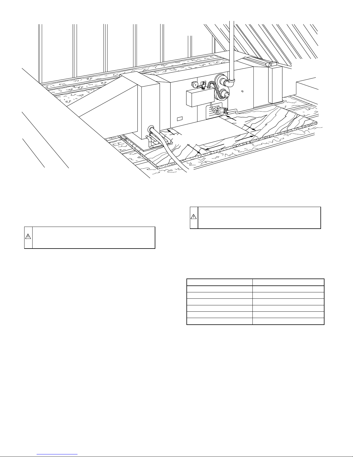
SHEET
30-IN. MIN
WORK AREA
METAL
Fig. 3—Typical Attic Installation
24″
24″
A96070
II. HORIZONTAL ATTIC INSTALLATION
The furnace can be installed horizontally for either left- or
right-side supply. See Fig. 3 for a typical attic installation and
Reversing Procedure section for reversing airflow direction.
CAUTION: In attic installations, it is necessary to keep
insulation at least 12 in. away from any furnace opening.
Some types of insulating materials are combustible.
1. Construct a working platform on location where all required
furnace clearances are met. (See Table 1 and Fig. 3.)
2. Position furnace in desired location.
3. Connect gas supply pipe. See Fig. 4 for typical gas piping.
4. Connect supply- and return-air ducts.
5. Install 24- X 24-in. sheet metal shield on platform in front
of controls as shown in Fig. 3.
III. HORIZONTAL CRAWLSPACE INSTALLATION
The furnace can be installed horizontally for either left- or
right-side supply. In a crawlspace, the furnace can either be hung
from floor joists or installed on suitable blocks or a pad. The
furnace can be suspended using steel pipe straps around each end
of furnace. These straps should be attached to furnace with sheet
metal screws and to floor joists with lag bolts. A framed assembly
of angle iron suspended with all-thread rod of suitable diameter
may be used to support the length of furnace. Refer to Fig. 1 for
size and weight of furnace. Care must be taken to allow for blower
door access.
The horizontal crawlspace installation is very similar to the attic.
Refer to Horizontal Attic Installation section, items 2, 3, 4, and 5.
A 24- X 24-in. sheet metal shield must be installed above the
controls for crawlspace installations. Extend sheet metal shield
over furnace top far enough to cover gas pipe entry hole.
IV. FILTER ARRANGEMENT
CAUTION: Never operate the unit without a filter or
with the filter removed. Failure to follow this caution can
result in a fire, personal injury, or death.
A factory-supplied filter and wire filter retainer are shipped with
furnace. After return-air duct has been connected to furnace, install
filter in blower compartment, just ahead of return-air plenum, and
secure it with wire filter retainer. The cross-mesh binding side of
filter should face blower. Refer to Table 2 for filter sizes.
TABLE 2—FILTER SIZE (IN.)
UNIT SIZE FILTER SIZE
036050 13X23
036075 13X23
048075 13X23
048100 16-1/2 X 23
060100 16-1/2 X 23
060125 20X23
V. GAS PIPING
Gas piping must be installed in accordance with national and local
codes. Refer to the current edition of the NFGC.
Canadian installations must be installed in accordance with the
NSCNGPIC and all authorities having jurisdiction.
Gas piping shall be of such size and so installed as to provide a
supply of gas sufficient to meet maximum demands without undue
loss of pressure between gas meter and furnace. It is recommended
that the gas supply line be a separate line running directly from
meter to furnace, unless existing gas line is of ample capacity.
Refer to Table 3 for recommended gas pipe sizing. Risers must be
used to connect to furnace and to meter.
Support all piping with appropriate straps, hangers, etc. Use a
minimum of 1 hanger every 72 in.
Joint compounds (pipe dope) should be applied sparingly and only
to male threads of joints. This pipe dope must be resistant to the
action of propane gas.
—6—
 Loading...