

Browning 9566E Instruction Manual
Ball and Roller Bearings Installation Instructions
F O R M
PN 786515, PS-740-0001
9566E
Revised
July 2016
• Read and follow all instructions carefully.
• Disconnect and lock-out power before installation and maintenance.
Working on or near energized equipment can result in severe injury or death.
• Do not operate equipment without guards in place. Exposed equipment can
result in severe injury or death.
These instructions cover the set screw, eccentric locking and BOA™ concentric lock
ball and setscrew roller bearings. It is important that they be read in their entirety
before attempting installation or removal. The procedures indicated should be
carefully followed. Failure to do so can result in misinstallation which could cause
bearing performance problems as well as serious personal injury.
BEARINGS IN BOLT-ON HOUSINGS (UNITS)
1. CHECK AREA - Clean and organize bearing installation area, and keep well lit.
Be sure mounting surfaces are clean and flat.
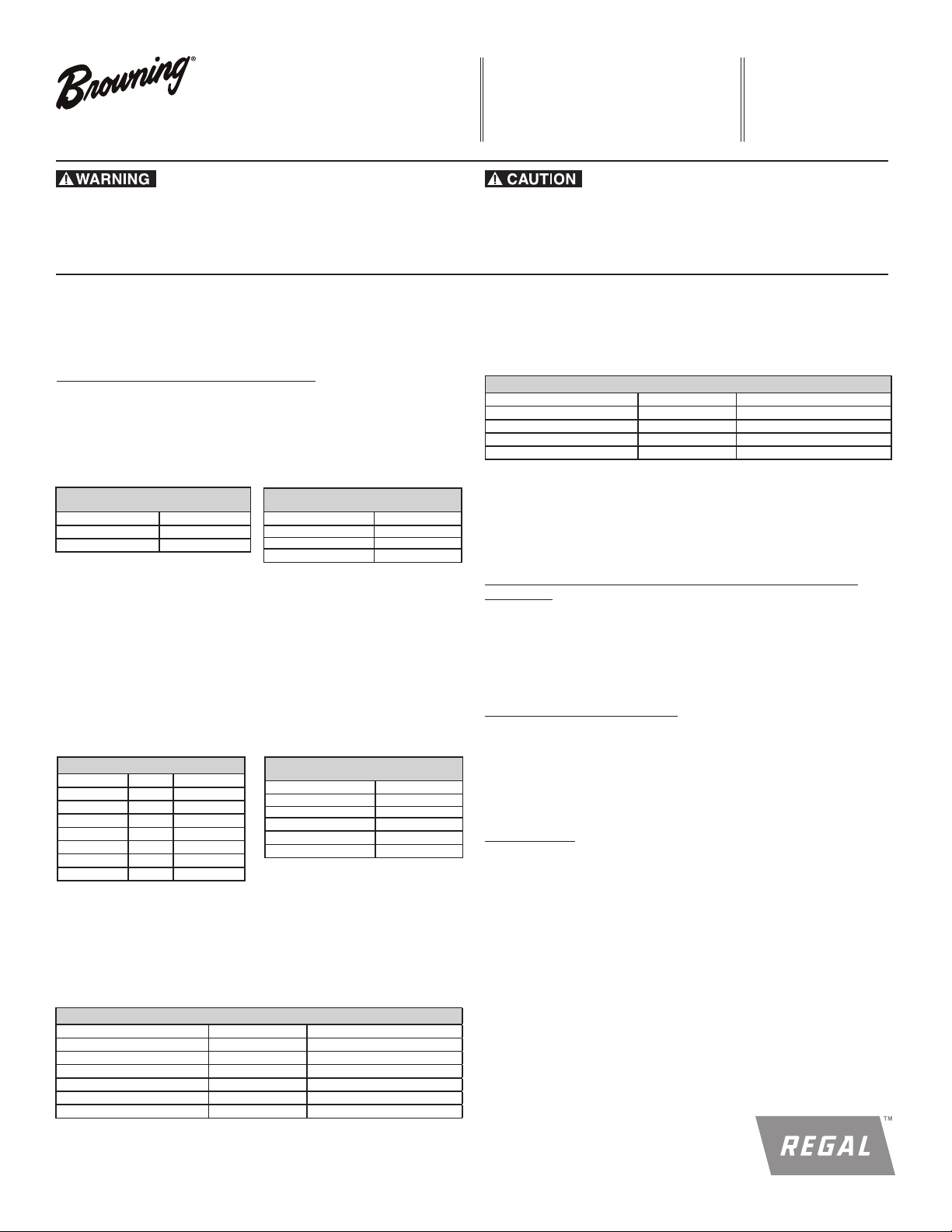
2. CHECK SHAFT - Shaft should be within tolerance range shown in Table
1, clean, and free of nicks and burrs. Mount bearing on unused section of
shafting or repair/replace shafting as required.
Table 1
Nominal Bore Diameter Tolerance (Inches)
3. INSTALL UNIT - Slide unit onto shaft. If it is difficult to mount bearing on
4. FASTEN UNIT IN PLACE - Install housing mounting bolts, check and align
5.1 SET SCREW INSERTS
Table 2
Ball Bearing Recommended Torque
Screw Size Hex Size Inch-Pounds
1/4-28 1/8 65 - 85
5/16-24 5/32 125 - 165
3/8-24 3/16 230 - 300
7/16-20 7/32 350 - 450
1/2-20 1/4 500 - 650
5/8-18 5/16 1100 - 1440
5.2 ECCENTRIC LOCK INSERTS
Table 3
Ball Bearing
Recommended Shaft Tolerances
1/2 - 1 15/16 +0.0000 / -0.0005
2 - 2 7/16 +0.0000 / -0.0010
Nominal Bore Diameter Tolerance (Inches)
Roller Bearing
Recommended Shaft Tolerances
1 1/8 - 2 +0.0000 / -0.0005
2 3/16 - 4 +0.0000 / -0.0010
4 7/16 -5 +0.0000 / -0.0015
shaft, use a piece of emery cloth to reduce any high spots on shaft. Do not
hammer on any component of the bearing
bearing and tighten mounting bolts to recommended fastener torques.
Exercising extreme caution and safety, rotate shaft slowly to center bearing.
a. Setscrews in a multiple bearing setup should be aligned.
b. Torque first set screw to one half recommended torque in Table 2. Torque
second set screw to full torque. Torque first set screw to full torque.
c. Repeat step 5b on opposite end of inner ring for roller bearings.
Roller Bearing
Lock Collar Setscrew Torque
10-32 3/32 30 - 35
Bore Size Foot-Pounds
1 3/16 - 1 11/16 12
1 3/4 - 2 1/2 19
2 11/16 - 3 1/2 45
3 15/16 - 4 95
4 7/16 - 5 150
a. Place collar on inner race and rotate by hand in direction of shaft rotation
until eccentrics are engaged.
b. Insert drift pin into the hole in the collar O.D. and lock in direction of shaft
rotation with the aid of small hammer.
c. Torque single setscrew to recommended torque in Table 3.
Screw Size Hex Size Inch-Pounds
1/4-28 1/8 65 - 85
5/16-24 5/32 125 - 165
3/8-24 3/16 230 - 300
7/16-20 7/32 350 - 450
1/2-20 1/4 500 - 650
5/8-18 5/16 1100 - 1400
Eccentric Locking Recommended Torque
• Periodic inspections should be performed. Failure to perform proper maintenance
can result in premature product failure and personal injury.
5.3 BOA CONCENTRIC INSERTS
a. Be sure that the BOA collar is fitted square and snug against the shoulder
on the inner ring.
b. Torque the BOA collar cap screw to torque recommended in Table 4.
Table 4
BOA Concentric Locking Collar Cap Screw Torque
Screw Size Hex Size Inch-Pounds
# 8-32 T-25 70
# 10-24 T-27 100
1/4-20 T-30 240
5/16-18 T-45 495
6. MONITOR INSTALLED BEARING - After bearing has been run for several
minutes, and again after several hours, check bearing for excessive noise or
vibration. Shutdown machine and check housing temp: typical applications
operate at 100°F - 150°F (38°C - 66°C). Check tightness of all locking devices
after 500 hours or 3 months, whichever comes first.
CYLINDRICAL OD INSERTS AND INSERTS IN CYLINDRICAL OD
HOUSINGS
INSTALL INSERT- Be sure housing bore is clean and free of debris. Press bearing
into housing by applying force to face of outer ring. Do not hammer on any
component of the bearing or apply force to inner ring. Proceed with Step
#1- 6 above. For recommended housing bore tolerance, consult catalog or contact
Application Engineering.
SPHERICAL OD BALL BEARINGS
Important: Replacement Browning bearing inserts are intended for use in
Browning housings. Housings should be thoroughly inspected for damage
such as cracks, excessive wear or galling of the spherical seat, obstruction of
grease port, etc. prior to installation.
INSTALL INSERT- Housing bearing seat should be wiped clean. Check grease
port and clean free of debris. Wet housing bearing seat with oil or grease. Secure
housing in a vise.
For Spherical OD:
a. Place the bearing insert into the housing load slots, positioning the anti
rotation rivet on the outer ring in the load slot as to not shear it off when
swinging insert into place. Also, position the outer ring lubrication hole so it
will install in line with the housing lubrication hole.
b. Using a bar placed in the insert bore as a lever, swing the insert into place
within the housing. Insert should have a snug fit in the housing. If insert can
be made to swivel by hand in the housing bore, fit is too lose and entire unit
should be replaced. If heavy force is required, fit is too tight and entire unit
should be replaced.
c. Ensure alignment of the anti rotation rivet in the load slot and outer ring
lubrication hole in the housing lubrication hole.

RELUBRICATION INSTRUCTIONS
All Browning Ball bearings and E920 Tapered Roller bearings are delivered with a
high quality lithium complex grease with an EP additive. The bearing is ready for
use with no initial lubrication required. The grease consists of a lithium complex
thickener, mineral oil, and NLGI grade 2 consistency.
Compatibility of grease is critical; therefore consult with Application Engineering
and your grease supplier to insure greases are compatible. For best performance
it is recommended to relubricate with lithium complex thickened grease with a
comparable NLGI consistency and base oil properties.
Relubricatable Browning bearings are supplied with grease fittings or zerks for
ease of lubrication with hand or automatic grease guns. Always wipe the fitting and
grease nozzle clean.
CAUTION: If possible, it is recommended to lubricate the bearing while rotating,
until grease purge is seen from the seals. If this is not an option due to safety
reasons, follow the alternate lubrication procedure below.
Re-Lubrication Procedure:
Stop rotating equipment. Add one half of the recommended amount shown in
Table 5 or 6. Start the bearing and run for a few minutes. Stop the bearing and add
the second half of the recommended amount. A temperature rise after lubrication,
sometimes 30°F (17°C), is normal. Bearing should operate at temperatures less than
200°F (94°C) and should not exceed 250° (121°C) for intermittent operation. For
lubrication guidelines, see Table 7.
Note: Grease charges in Table 5 and 6 are based on the use of lithium complex
thickened grease with a NLGI grade 2 consistency.
Note: Table 7 contains general recommendations. Experience and testing may be
required for specific applications.
Table 5
Ball Bearing
Recommended Lubrication Grease Charge
Shaft Size
100 & 200 Series 300 Series
Intermediate &
Standard Duty
1/2 -5/8 x 0.02
3/4 x 0.03
13/16 - 1 x 0.03
1 1/16 -1/4S 15/16 - 1 0.06
1 1/4 - 1 7/16 1 3/16 0.09
1 1/2 - 1 9/16 1 7/16 0.14
1 5/8 - 1 3/4 1 1/2 0.16
1 13/16 - 2S 1 11/16 - 1 3/4 0.18
2 - 2 3/16 1 15/16 0.25
2 1/4 - 2 7/16 2 3/16 0.35
Table 6
Medium Duty
Roller Bearing
Recommended Lubrication Grease Charge
Bore Size Grease Charge (Mass - Ounces)
1 3/16 - 1 1/4 0.26
1 3/8 - 1 7/16 0.30
1 1/2 - 1 11/16 0.36
1 3/4 - 2 0.42
2 3/16 0.69
2 1/4 - 2 1/2 0.75
2 11/16 - 3 0.92
3 3/16 - 3 1/2 1.50
3 15/16 - 4 1.92
4 7/16 - 4 1/2 2.79
4 15/16 - 5 4.17
Grease Charge
(Mass - Ounces)
Table 7
Ball and Roller Bearing
General Lubrication Schedule
Environment Temperature (°F)
Dirty -20 to 200 0 - 100% Daily to 1 Week
-20 to 125
Clean
125 to 175
175 to 200 0 - 100% Daily to 1 Week
Table 8
Speed
(% Catalog Max)
0 - 25% 4 to 10 Months
26 - 50% 1 to 4 Months
51 - 75% 1 Week to 1 Month
76 - 100% Daily to 1 Week
0 - 25% 2 to 6 Weeks
26 - 50% 1 Week to 1 Month
51 - 75%
76 - 100%
Daily to 1 Week
Ball Bearing
Maximum Operational Speed
100 & 200 Series 300 Series
Bore Size Speed (RPM) Bore Size Speed (RPM)
1/2 -5/8 7500 1 4500
3/4 6500 1 3/16 - 1 1/4 4000
7/8 - 1 5500 1 7/16 3500
1 1/6 -1 1/4S 4500 1 1/2 - 1 3/4 3000
1 1/4 - 1 7/16 4000 1 15/16 - 2 3/16 2500
1 1/2 - 1 9/16 3500 - -
1 5/8 - 2S 3000 - -
2 - 2 7/16 2500 - -
Table 9
Roller Bearing
Maximum Operational Speed
Maximum Operational Speed
Bore Size Speed (RPM)
1 3/16 - 1 1/4 3500
1 3/8 - 1 7/16 3000
1 1/2 - 1 11/16 2500
1 3/4 - 2 3/16 2000
2 1/4 - 2 1/2 1750
2 11/16 - 3 150 0
3 3/16 - 4 1000
4 7/16 - 5 750
Frequency
Regal and Browning are trademarks of Regal Beloit Corporation or one of its affiliated companies.
©2016 Regal Beloit Corporation, All Rights Reserved. MCIM16046E • Form 9566E • Printed in USA
 Loading...