

Browning 9191E Instruction Manual
TorqTaper® Plus Helical Shaft Mount
Speed Reducers Installation
and Maintenance Manual
F O R M
9191E
Revised
September 2015
• Read and follow all instructions carefully.
• Disconnect and lock-out power before installation and maintenance.
Working on or near energized equipment can result in severe injury or death.
• Do not operate equipment without guards in place. Exposed equipment can
result in severe injury or death.
• Never lift the reducer by the input shaft. Lifting lug should only be used to lift the
weight of the reducer. Do not use lifting lug to lift attached assemblies.
• Reducer shipped without oil. Fill to proper level before operation to avoid
damage and/or personal injury. Do not use lubricants with anti-wear/extreme
pressure additives in units with internal backstops - these additives decrease the
backstops’s ability to prevent reverse rotation and will result in backstop failure
which could cause personal injury.
• Periodic inspections should be performed. Failure to perform proper maintenance
can result in premature product failure and personal injury.
• All electrical work should be performed by qualied personnel and compliant with
local and national electrical codes.
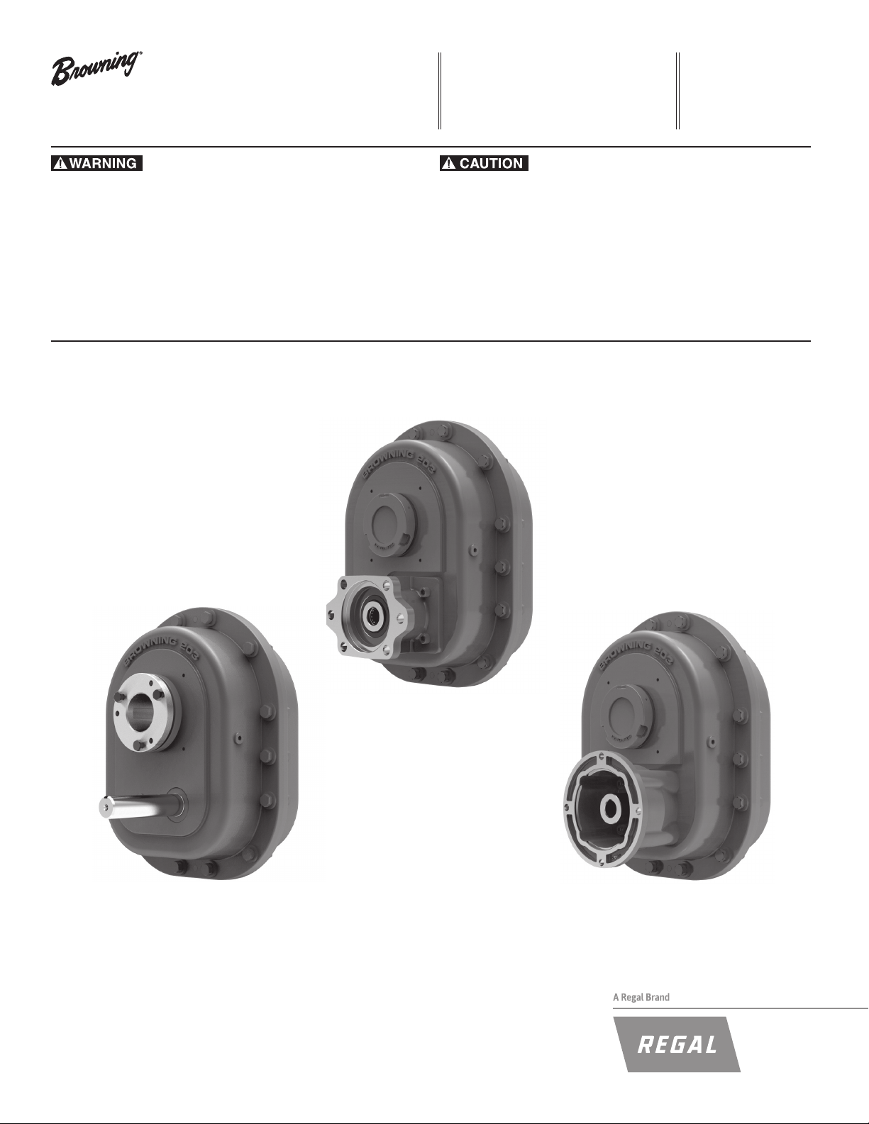
Shaft Mount TorqTaper Plus
Hydraulic TorqTaper Plus
C-Face TorqTaper Plus
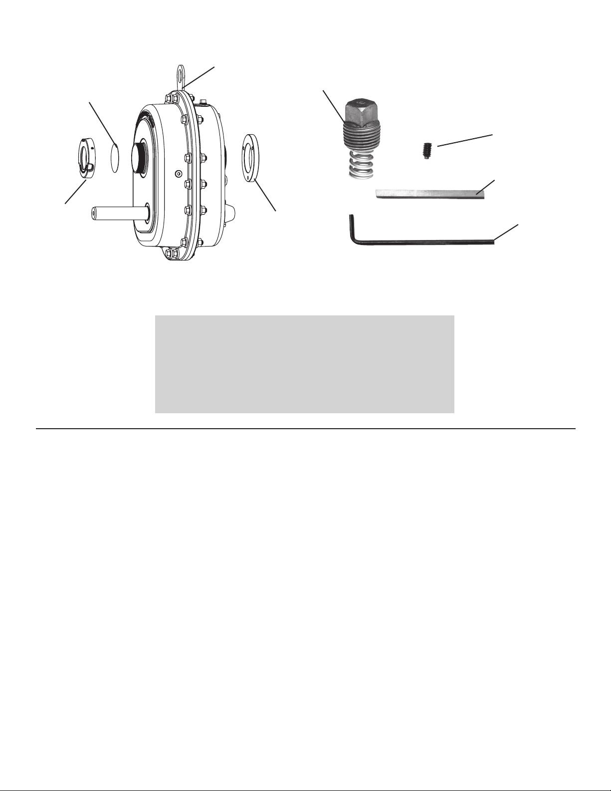
Parts Included with Reducer
Dirt cover
Lifting Lug
Breather
Shipped with
reducer in a
separate bag
Spare nylon
tipped set screw
for end cap
Input shaft key
End cap
Note: Bushing ring, end cap and dirt cover are installed on the reducer prior
to shipment.
Bushing ring
Available TorqTaper Plus Accessory Kits
• Torque Arm Kit
• Motor Mount Kit
• Tapered Bore Bushing Kit
• Vertical Shaft Mount Breather Kit
• Filtered Breather Kit
• Screw Conveyor Adaptor Kit
• Screw Conveyor Drive Shaft Kit
• Packing Gland Kit
• Waste Pack Kit
• Bushing Guard Kit
• Pump and Cooler Kit
• Belt Guard Kit
• Fan Kit
• Backstop Kit
Table of Contents
1. Shaft Mount Reducer Installation Instructions ..........................................................................................................................3
1.1 Reducer and Driven Shaft Preparation ............................................................................................................................ 3
1.2 Determine Mounting Conguration .................................................................................................................................. 3
1.3 Front Mounting Conguration with Stabilizer Ring ........................................................................................................... 3
1.4 Rear Mounting Conguration with Stabilizer Ring ............................................................................................................ 4
1.5 Rear Mounting Conguration without Stabilizer Ring ....................................................................................................... 4
1.6 Installation Instructions Finished Bore Model ................................................................................................................... 5
2. Lubrication Instructions ..............................................................................................................................................................5
2.1 Oil Level .......................................................................................................................................................................... 6
2.2 Relubrication Maintenance Schedule ............................................................................................................................... 8
2.3 Lubricant Selection ........................................................................................................................................................... 8
3. Hydraulic and C-face Motor Mount Installation Instructions ................................................................................................... 9
3.1 Hydraulic Motor Mounting ............................................................................................................................................................................ 9
3.2 C-Face Motor Mounting ............................................................................................................................................................................... 9
4. Installation Checklist ...................................................................................................................................................................9
5. Shaft Mount Removal Instructions ............................................................................................................................................. 9
5.1 Bushed Bore Model .......................................................................................................................................................... 9
5.2 Finished Bore Model ........................................................................................................................................................ 9
6. BoltTorqueSpecications .......................................................................................................................................................... 9
7. Shaft Mount Terminology .......................................................................................................................................................... 10
Allen wrench
for end cap
set screw
Page No.
1. Shaft Mount Reducer Installation Instructions
BUSHING
KEY SHO
BUSHING
EXTERNAL KEY FURNISHED
Y
MC
For long service and dependable performance, a shaft mount reducer must be rigidly
supported and accurately aligned. The following instructions are a step-by-step
guide to meeting these requirements for a Browning® TorqTaper Plus shaft mounted
reducer. If there is a need to vary from any of these installation instructions, contact
the Regal Power Transmission Solutions Application Engineering Department at
1-800-626-2093 before completing the installation.
CAUTION: Shaft mounted reducers use bushings to mount the reducer to
various driven shaft sizes. When the driven shaft is smaller than the maximum
bushing size for the reducer, check the driven shaft and key stresses per ANSI/
AGMA Std. 6001-D97 for the application.
1.1 Reducer and Driven Shaft Preparation
1.1.1 The driven shaft diameter is to be within the commercial tolerances for
turned and polished round bars. The key and keyseat in the driven shaft are to be in
accordance with commercial standards for size, depth, offset, lead and parallelism.
1.1.2 The driven shaft on which the reducer is to be mounted must be straight, clean
and free of burrs.
1.1.3 Rotate the driven shaft on which the reducer is to be mounted so the shaft
keyseat is in the upward position.
1.1.4 A lifting lug is provided to lift the reducer into position. The lifting lug may be
repositioned onto any one of the housing ange bolts as required. After repositioning,
all housing ange bolts must be reinstalled to the recommended torque. See bolt
torque specications section.
CAUTION: Do not apply grease, oil or an anti-seize compound to the taper
bore of the reducer, barrel of the bushing, driven shaft or bushing bore. If any of
these substances are applied, equipment failure and personal injury may result.
1.2.4 Using the appropriate reducer size in the Tables 1-3, 1-4 and 1-5, compare
the measured values for H and K to the tabulated values of H and K. If the measured
values for H and K are greater than the tabulated values, the mounting conguration
shown in the gure may be used. If the measured values for H and K are less than the
tabulated values, proceed to the next gure and repeat this step.
Notice: If the measured values for H and K are less than the tabulated values
shown in Table 1-5, contact the Regal Power Transmission Solutions Application
Engineering Department at 1-800-626-2093.
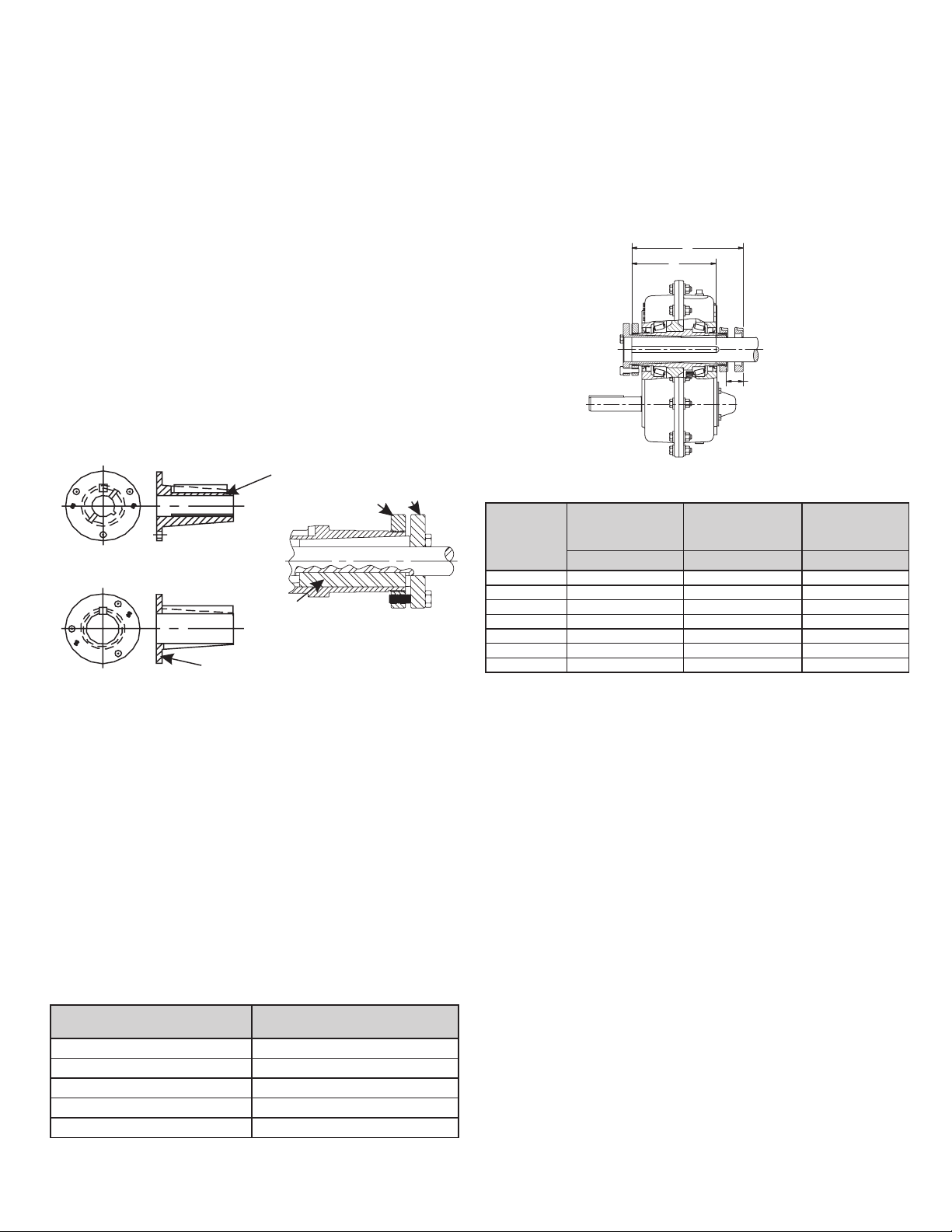
1.3FrontMountingCongurationwithStabilizerRing(107through315)
Figure 1-3
FrontMountingCongurationwithStabilizerRing(107through315)
H
K
EXTERNAL KE
BUSHING
RING
TYPE 1
BUSHIN
G
TYPE 2
WN
FOR TYPE 2
BUSHING
FIGURE 1-2
BUSHING
TYPE
BUSHIN
THROUGH KEY FURNISHED
FLANGE
2
G
FIGURE 1-1
1.2 DetermineMountingConguration-BushedBoreModels
Due to its unique design, the Browning TorqTaper Plus shaft mounted reducer may be
mounted to a driven shaft in a variety of congurations. The following instructions will
help determine the correct mounting conguration based on the available driven shaft
and key length.
1.2.1 Measure the available driven shaft length “H” (in inches) starting from the end of
the driven shaft to the rst obstruction or point of interference.
1.2.2 Measure the length of the available keyseat “K” in the driven shaft (in inches)
starting from the end of the driven shaft to the end of the usable keyseat.
1.2.3 The following Sections - 1.3, 1.4 and 1.5, show the three standard mounting
congurations for the Browning TorqTaper Plus shaft mounted reducer. Refer to the
following sections in sequence to determine the optimum mounting conguration for the
application.
Table 1–2 Shaft Diameter Tolerances for Inch Shafts
Shaft diameter, in Maximum undersize variation, in¹
Over 1.50 to 2.50 0.005
Over 2.50 to 4.00 0.006
Over 4.00 to 6.00 0.007
Over 6.00 to 8.00 0.008
Note:
¹) Keys and keyways in supporting shaft should be in accordance with
ANSI B17.1 for size, depth, offset, lead and parallelism.
To 1.50 0.004
Table1-3DimensionsforFrontMountingConguration
with Stabilizer Ring (107 through 315)
MINIMUM
Unit
Size
MINIMUM
CLEARANCE
SHAFT
MOUNTING
LENGTH
MC H K
107 0.97 8.06 3.69
115 1.03 8.59 3.88
203 1.15 9.78 4.32
207 1.21 10.16 4.81
215 1.31 11.36 5.25
307 1.44 13.04 6.31
315 1.69 15.20 7.38
1.3.1 On the input shaft side of the quill, thread the bushing ring onto the hollow quill
one or two turns past the end of the quill.
1.3.2 Place the endcap on the driven shaft with the threaded bore facing the end of
the shaft. Slide the stabilizer ring on the driven shaft with the small end of the taper
toward the end of the shaft.
1.3.3 Install Key(s)
Type 1 Bushing (2 Keys):
• Install the external bushing key into the bushing as shown in Fig 1-1
(External bushing key is supplied with the Bushing Kit)
• Install driven shaft key (customer supplied) into the driven shaft keyseat.
Position the end of the driven shaft key even with the end of driven shaft.
Retain this key to prevent movement.
1.3.4 Install Reducer
Type 1 Bushing
• Mount the reducer on the driven shaft with the bushing ring facing outward
toward the end of the driven shaft.
• Locate the reducer on the driven shaft such that approximately .500 inch of
the driven shaft extends out beyond the end of the reducer quill.
• Start the bushing (small end rst) by aligning the keyway in the bushing with
the key previously installed in the driven shaft.
• Continue moving the bushing into position and rotate the input shaft as
required to align the external bushing key with the keyway in the reducer
quill.
• Rotate the bushing ring clockwise to align the clearance holes in the bushing
with the threaded holes in the bushing ring. (This will require less than ½
turn of the bushing ring).
• Install the bushing capscrews and hand tighten. Reposition the reducer until
the end of the driven shaft is even with the end of quill.
• Slide the stabilizer ring into the reducer quill and thread the endcap on hand
tight
• See bolt torque specications section.
• Tighten the bushing capscrews evenly around the bushing ange to the
recommended torque as shown in Table 6-1.
• Tighten the endcap again until hand tight. Tighten the set screw in the
endcap to the recommended torque as shown in Table 6-1.
MINIMUM
KEY
CONNECTION
LENGTH
 Loading...