

Browning 8658E Instruction Manual
V-Belt
Installation Instructions
F O R M
8658E
Revised
July 2018
• Read and follow all instructions carefully.
• Disconnect and lock out power before installation and
maintenance. Working on or near energized equipment can
result in severe injury or death.
• Do not operate equipment without guards in place. Exposed
equipment can result in severe injury or death.
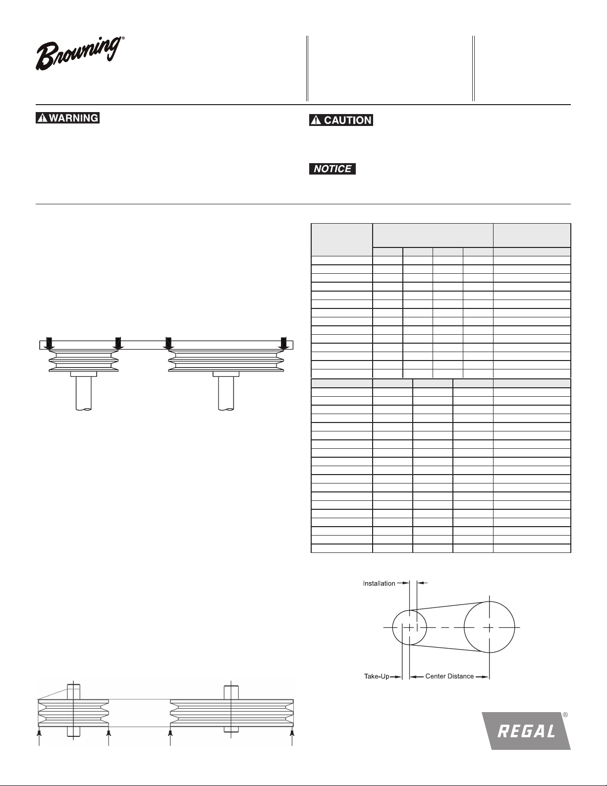
V-Belt Sheave Alignment
Before installing the bushings, refer to Form No. F20-23 for Q-D® instructions and Form No. 4013 for Browning Split Taper® instructions. After
installing the bushings in the sheaves and the resulting assemblies onto
the shafts, use a straight edge or string placed on the outside face of both
sheaves to adjust parallel offset and angular alignments. The straight edge
or string should be close to the shafts and contact each sheave as shown
in the figure 1 and 2 below. The objective is to have the shafts parallel and
the center lines of the two sheaves in line.
Figure 1
Four Point Contact with Straightedge
• Periodic inspections should be performed. Failure to perform
proper maintenance can result in premature product failure and
personal injury.
• Do not pry or otherwise force belts onto sheave. Doing so may
result in permanent damage to the belt.
TABLE 1: CENTER DISTANCE ALLOWANCE
Belt No.
26 - 35 .8 1. 0 - - 1. 0
38 - 55 .8 1. 0 1. 5 - 1. 5
60 - 85 .8 1. 3 1. 5 - 2.0
90 - 112 1. 0 1. 3 1. 5 - 2.5
120 - 144 1. 0 1. 3 1. 5 2.0 3.0
158 - 180 - 1.3 2.0 2.0 3.5
195 - 210 - 1.5 2.0 2.0 4.0
240 - 1.5 2.0 2.5 4.5
220 - 300 - 1. 5 2.0 2.5 5.0
330 - 390 - - 2.0 2.5 6.0
420 and over - - 2.3 3.0 1 1/2% of Belt Length
250 - 475 .5 1. 0
500 - 710 .8 1.0 1. 2
750 - 1060 .8 1. 0 1. 5 1. 5
Allowance for Installation
4L, A 5L, B C D All Sections
3V 5V 8V All Sections
Allowance for Initial
Tensioning and
Subsequent Take-Up
Belt drives should be aligned as perfect as possible to maximize drive life.
The practical maximum misalignment is stated as the angle at which the
belt enters the sheave, and is 1/2 degree. This angle is a result of both
angular and parallel offset misalignment.
V-Belt Installation
Some means must be employed to allow tensioning the belts. These
steps describe an application having adjustable center distance. If the
design has fixed, non-movable centers then other means of tensioning
must be considered such as idlers and drive tighteners. Contact
Application Engineering at 1-800-626-2093 for additional assistance.
Step 1: Loosen moveable base bolts (or motor base bolts) and move
sheaves close to facilitate installation of belt. See Table 1 for minimum
installation allowance.
Step 2: Move all the slack in multiple belt drives to one side, then
remove the slack (increase centers). Then rotate sheaves several
revolutions by hand to equalize belt tensions.
Step 3: Tension belts as outlined on the next page.
Note: If Browning Tension Checker is used, only 35 lbs maximum force
(F) can be obtained. If higher forces are required, use other means such
as dead weights or hydraulic pressure to apply a known force.
Figure 2
Four Point Contact on Both Sides with String
1120 - 1250 .8 1. 0 1. 5 1. 8
1320 - 1700 .8 1. 0 1. 5 2.2
1800 - 2000 1. 0 1. 8 2.5
2120 - 2240 1.2 1. 8 2.8
2360 1. 2 1. 8 3.0
2500 - 2650 1. 2 1. 8 3.2
2800 - 3000 1. 2 1. 8 3.5
3150 1.2 1. 8 4.0
3350 - 3550 1. 5 2.0 4.0
3750 - 2.0 4.5
4000 - 5000 - 2.0 5.5
5600 - 2.0 6.0
Figure 3
1
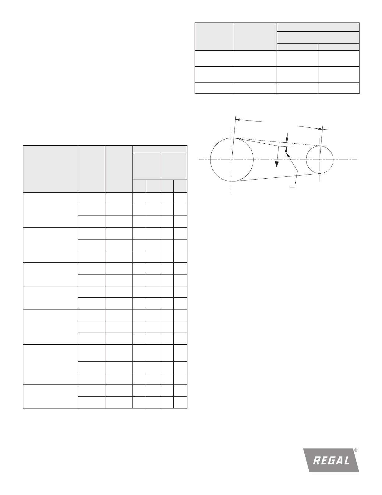
Force
Span Length, t
Deflection (def)
Tensioning V-Belts
Calculate or measure the belt span length as shown in Figure 3. Calculate
the required deflection by multiplying this number by 1/64. For example,
if the belt span is 32 inches, 32 x 1/64 = 1/2 inch deflection. Increase the
belt tension by increasing the center distance (or adjusting the idler, if
present). Apply the force listed in Table 2 to any one of the belts in the
drive at the center of the belt span until the calculated deflection amount
is reached. Drives with shock loading or other unusual conditions may require increased tension. Always check to be sure bearings can handle the
loads. Excessively high or low tensions will affect belt life. Recheck belt
tensions after jog start or 1-3 minutes of operation, and 8 hours, 24 hours,
100 hours, and periodically thereafter.
Belt
Cross
Section
3L
4L
5L
Smallest Sheave
Diameter Range
1.25 - 1.75
2.00 - 2.25
2.50 - 3.00
2.10 - 2.80
3.00 - 3.50
3.70 - 5.00
3.00 - 4.20
4.50 - 5.20
Belt deection force
Super Gripbelts and
Unnotched Gripbands
Used Belt New Belt
1 5/
1
2 1/
3
/
8
3
/
4
1
5
/
8
8
2
1
/
2
2
1 1/
1 1/
2
2 5/
3 1/
5
/
8
4
2
1
1
/
2
3
8
2
TABLE 2
SHEAVE DIAM - INCHES
DEFLECTION FORCE - LBS.
The values in Table 2 are general in nature providing deflection force to
cover a wide range of drives. For precise deflection force refer to our
EDGE online V-Belt Drive Selection Program.
Belt deection force
Belt Cross Section
A - AX
B - BX
C - CX
D
3V - 3VX
5V - 5VX
8V
Smallest
Sheave
Diameter
Range
3.0 - 3.6
3.8 - 4.8
5.0 - 7.0
3.4 - 4.2
4.4 - 5.6
5.8 - 8.6
7.0 - 9.0
9.5 - 16.0
12.0 - 16.0
18.0 - 20.0
2.2 - 2.4
2.65 - 3.65
4.12 - 6.90
4.4 - 6.7
7.1 - 10.9
11.8 - 16.0
12.5 - 17.0
18.0 - 22.4
Super
Gripbelts
RPM
Range
1000 - 2500
2501 - 4000
1000 - 2500
2501 - 4000
1000 - 2500
2501 - 4000
860 - 2500
2501 - 4000----
860 - 2500
2501 - 4000
860 - 2500
2501 - 4000
500 - 1740
1741 - 3000
500 - 1740
1741 - 3000
200 - 850
851 - 1500
200 - 850
851 - 1500
1000 - 2500
2501 - 4000----
1000 - 2500
2501 - 4000
1000 - 2500
2501 - 4000
500 - 1749
1750 - 3000
3001 - 4000
500 - 1740
1741 - 3000
500 - 1740
1741 - 3000
200 - 850
851 - 1500
200 - 850
851 - 1500
and
Unnotched
Gripbands
Used
Belt
3.7
2.8
4.5
3.8
5.4
4.7
5.3
4.5
6.3
6.0
11.5
9.4
14.1
12.5
24.9
21.2
30.4
25.6
3.6
3.0
4.9
4.4
-
-
-
12.7
11.2
15.5
14.6
33.0
26.8
39.6
35.3
New
Used
Belt
5.5
4.2
6.8
5.7
8.0
7.0
7.9
6.7
9.4
8.9
17.0
13.8
21.0
18.5
37.0
31.3--
45.2
38.0--
5.1
4.4
7.3
6.6
-
-
-
18.9
16.7
23.4
21.8
49.3
39.9--
59.2
52.7--
Gripnotch
Belts and
Notched
Gripbands
Belt
4.1
3.4
5.0
4.3
5.7
5.1
4.9
4.2
7.1
6.1
8.5
7.3
14.7
11.9
15.9
14.6
3.3
2.9
4.2
3.8
5.3
4.9
10.2
8.8
5.6
14.8
13.7
17.1
16.8
New
Belt
6.1
5.0
7.4
6.4
8.4
7.6
7.2
6.2
10.5
9.1
12.6
10.9
21.8
17.5
23.5
21.6
-
-
-
-
4.9
4.3
6.2
5.6
7.9
7.3
15.2
13.2
8.5
22.1
20.1
25.5
25.0
-
-
-
-
Figure 4
Note: For gripbands (multiple or banded belts), the belt deflection force table
2 must be multiplied by the number of ribs in the gripband. Lay a narrow steel
bar such as keystock across the gripband belt and apply the belt deflection
force to the bar such that all the individual ribs are deflected evenly.
General Notes
Do not install new belts in worn sheave grooves. Such sheaves should be
replaced with new ones to insure a proper fit of the belts in the grooves.
Keep belts clean. Do not use belt dressing.
When replacing belts on a drive, be sure to replace the entire set with a
new set of matched belts. Keep extra belts stored in a cool, dark, dry
place.
Regal, Browning, Q-D and Spilt Taper are trademarks of Regal Beloit Corporation or one of its afliated companies.
©2015, 2018 Regal Beloit Corporation, All Rights Reserved. MCIM18014E • Form# 658E
2
 Loading...