

HTP® Installation Instruction
Center Distance
Take-Up
Installation
F O R M
8600-AE
Revised
September 2015
• Read and follow all instructions carefully.
• Disconnect and lock-out power before installation and maintenance.
Working on or near energized equipment can result in severe injury or death.
• Do not operate equipment without guards in place. Exposed equipment can
result in severe injury or death.
• Be sure drive system cannot rotate during installation. Failure to do so
can result in serious injury.
HPT Sprocket Alignment
Before installing bushings, refer to EPT Form #F20-23 for QD® Instructions and
to Form No. 4013 for Split Taper Instructions. After installing the bushings in the
sprockets and the resulting assemblies onto the shafts, use a straight edge, piano
wire, or string placed on the outside face of both sprockets to adjust parallel offset
and angular alignments. The straight edge, piano wire, or string should be close to
the shafts and contact each sprocket in two places on the anges (or on the face of
an unanged pulley). The objective is to have the shafts parallel and the center lines
of the two sprocket faces in line. See Figure 1 below.
Figure 1
Belt drives should be aligned as perfect as possible to maximize drive life. The
practical maximum misalignment is stated as the angle at which the belt enters the
sprocket. This angle is a result of both angular and parallel offset misalignment, and
is 1/4 degree.
HPT Belt Installation
Condition A – One Flanged Sprocket and One Unanged Sprocket.
After sprockets have been mounted and aligned, reduce the shaft center distance
as shown in Table 1. Put the belt over the anged sprocket rst, then slip onto the
unanged sprocket.
Condition B – Both Sprockets Flanged. After sprockets have been mounted and
aligned, reduce the shaft center distance as shown in Table 1. Put the belt over the
larger sprocket rst, then the smaller sprocket.
Condition C – Minimum Center Distance Adjustment.
1. Mount one sprocket onto the shaft loosely and put the belt on it.
2. Put the other sprocket into the belt loop and slip it onto the other shaft (bushing
loosely installed).
3. Align the drive and tighten the bushings. Timing belts have been designed to have
proper pitch dimensions under correct tensions. Belts may not fully seat in large
diameter pulleys without applying proper tension to the belt.
Figure 2
• Periodic inspections should be performed. Failure to perform proper maintenance
can result in premature product failure and personal injury.
• All electrical work should be performed by qualied personnel and compliant with
local and national electrical codes.
• Failure to use the cap screws that came with the Product may lead to an
unsafe assembly.
• To avoid damage, supporting structure including shafts and bearings must be
designed to handle transmitted loads and belt tension(s).
• Shaft horizontal drives must have at least one anged pulley; shaft vertical drives
must have all pulleys anged, otherwise belt may come off.
• Do not pry or otherwise force belts onto sprockets. Doing so can result in
permanent damage to the belt.
TABLE 1 - CENTER DISTANCE ALLOWANCE
Belt Pitch
Length
Range
(MM)
up to 1440 .7” 1.0” 1.2” 2.2” .1” .1”
1441 to 2600 .8” 1.1” 1.3” 2.3” .2” .2”
over 2600 .9” 1.2” 1.4” 2.4” .3” .3”
Allowance for Installation (Inches)
Condition A Condition B Condition C
8MM
Belts
14MM
Belts
8MM
Belts
14MM
Belts
8MM
and
14MM Belts
Allowance
for Take-Up
8MM and
14MM Belts
HPT INSTALLATION INSTRUCTIONS
Tensioning HPT Belts
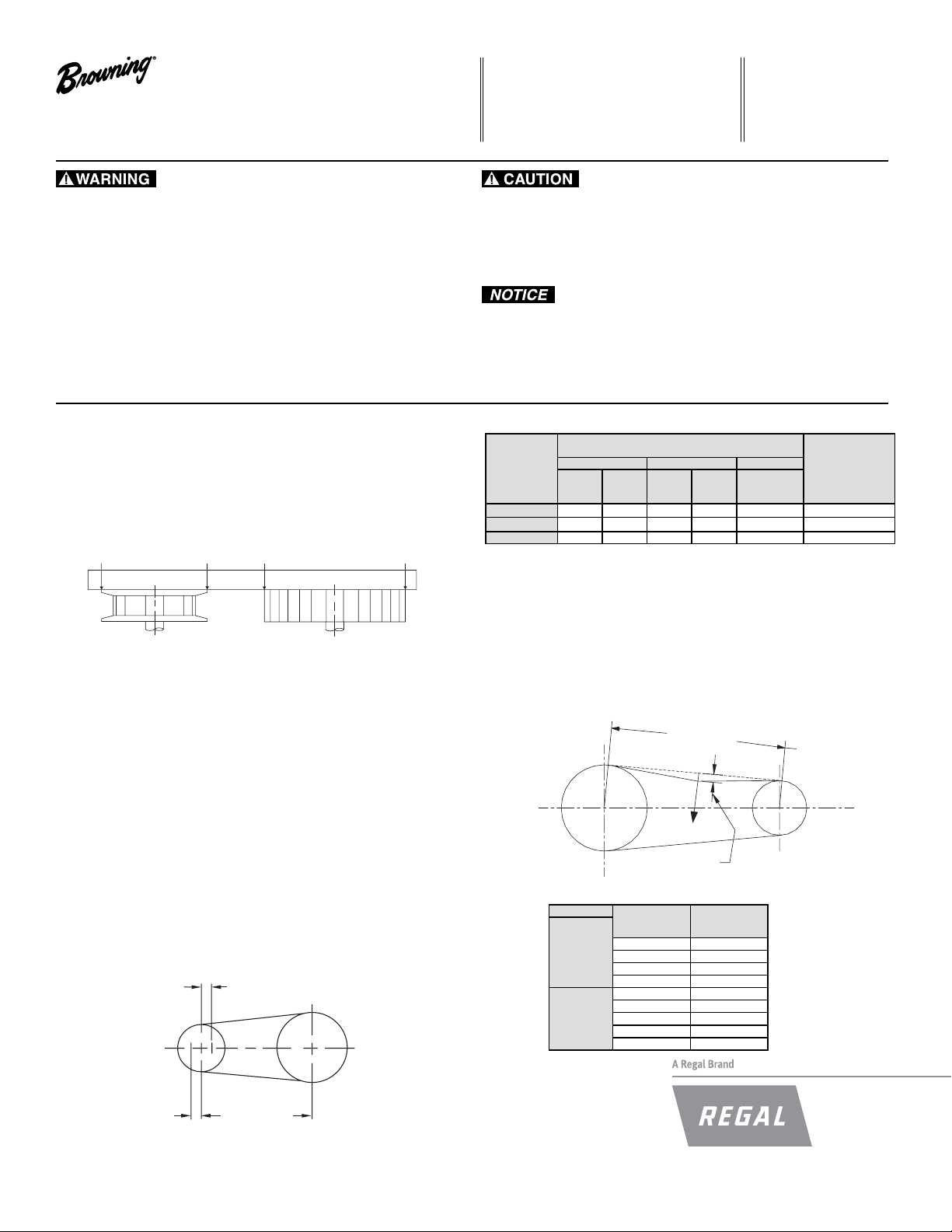
Calculate or measure the belt span length as shown in Figure 3. Calculate the
required deection by multiplying this number by 1/64. For example, if the belt span
is 32 inches32 x 1/64 = 1/2 inch deection. Increase the belt tension by increasing
the center distance (or adjusting the idler, if present). Apply the force listed in Table 2
evenly across the width of the belt at the center of the belt span. A strip of keystock
or similar material may be used to help distribute the force evenly across the belt
width. Drives with shock loading or other unusual conditions may require increased
tension. Always check to be sure bearings can handle the loads.
Figure 3
Span Length, t
Force
Deflection (def)
TABLE 2 - DEFLECTION FORCE FOR HPT BELTS (Lbs)
Pitch
8MM
14MM
Width
MM
20 4
30 6
50 11
85 19
40 11
55 16
85 26
115 37
170 58
Force
LBS
Browning and HPT are trademarks of Regal Beloit Corporation or one of its afliated companies.
©2015 Regal Beloit Corporation, All Rights Reserved. MCIM15064E • Form 8600-AE • Printed in USA
 Loading...