

MVP® Variable Speed Sheaves
Mounting and Adjusting Instructions
F O R M
4044E
Revised
December 2017
• Arc flash and shock hazard. Appropriate PPE required.
Failure to wear appropriate PPE will result in death or serious
injury.
• Read and follow all instructions carefully.
• Disconnect and lock out power before installation and
maintenance. Working on or near energized equipment can
result in severe injury or death.
• Do not operate equipment without guards in place. Exposed
equipment can result in severe injury or death.
• Periodic inspections should be performed. Failure to perform
proper maintenance can result in premature product failure and
personal injury.
• Do not pry or otherwise force belts onto sheave. Doing so may
result in permanent damage to the belt..
Straight Bore Sheave
Mounting:
1. Make sure the shaft, sheave bore, keys and keyways are free of burrs,
paint,
etc.
2. All straight bore sheaves should be mounted on the motor or driving
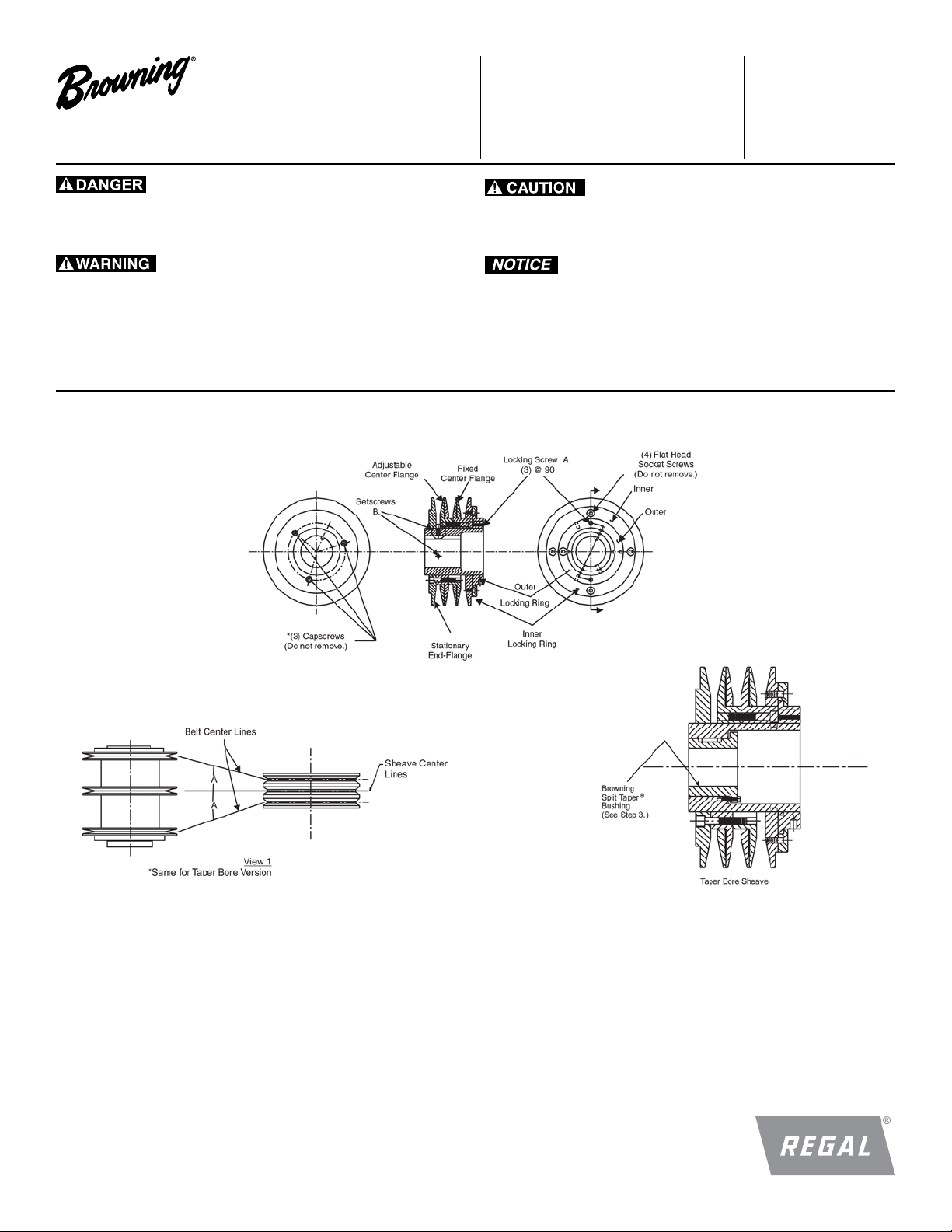
shaft with the end containing set screws “B” toward the motor.
Sheave should be located as close to the motor as possible with the
set screws “B” in full contact with the key and shaft. The shaft key is
provided with the sheave on some sizes.
3. If the sheave has a tapered bore to accommodate a Browning Split
Taper® Bushing, follow the instructions on the split taper bushing
box, or refer to Regal Form No. 4013 (Browning Split Taper bushing
instructions).
4. Be sure both driving and driven sheaves are in alignment and that
shafts are parallel. The centerline of the driving sheave must
line up with the centerline of the driven sheave. Angle “A” cannot
exceed 1/2° for raw edge belts and 2° for wrapped belts. See View 1.
5. For straight bore sheaves, tighten set screws “B” in place.
6. Be sure that all setscrews and capscrews are torqued to values
shown in Table A with a torque wrench before starting drive. Check
setscrew torque and belt tension after 24 hours service.
See Table A. Refer to Regal® Browning® Components Catalog,
“Tensioning V-Belt Drives,” or Regal Form No. 5453 (Belt Tension
Checker) for tensioning instructions.
1
Adjusting:
7. Slack off all belt tension by moving motor toward the driven shaft until
belts are free of grooves. For easiest adjustment, remove the belts
from the grooves.
8. Loosen, but don’t remove the three locking set screws “A” in outer
locking ring, by using a hex key or torque wrench with hex bit (key).
9. Adjust sheave to desired pitch diameter by turning the outer locking
ring. Three holes 120° apart are provided for a spanner wrench or drift
for ease of turning.
10. Any pitch diameter can be obtained within the sheave range. One
complete turn of the outer locking ring will result in a .233” change in
pitch diameter.
11. Opening sheaves more than shown below may lead to poor sheave
and belt performance.
Do not open “B” sheaves more than 4-3/4 turns for “A” belts or 6
turns for “B” belts.
Do not open “C” sheaves more than 9-1/2 turns.
Do not open “D” sheaves more than 13 turns.
Do not open “5V” sheaves more than 6 turns.
Do not open “8V” sheaves more than 8-1/2 turns.
12. Tighten all three locking screws “A” in the outer locking ring to the
value shown in Table A with a torque wrench and hex bit (key).
13. Replace belts and move motor away from driven shaft to tension
belts properly. Refer to Regal® Browning® Components Catalog,
“Tensioning V-Belt Drives”, or Regal Form No. 5453 (Belt Tension
Checker) for tensioning instructions. Check speed. If further
adjustment is needed, repeat the steps 7-12 above.
14. Do not loosen any screws other than the three locking screws “A” in
the outer locking ring. These screws should be loosened only while
the drive is at rest and adjustment is being made. Locking screws “A”
must be tightened before drive is operated after adjustment.
CAUTION: Tighten locking screws “A” to value shown with a torque
wrench and hex bit (key). Otherwise locking ring and flange may come off
the assembly during operation.
15. Field disassembly of sheave is not recommended. If it is felt that
complete disassembly is necessary, please contact application
engineering at 1-800-626-2093.
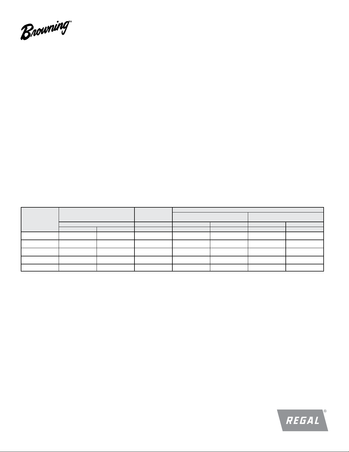
Table A
Nominal
screw size
(Dia.-Threads/In)
1
/4 - 20NC 150 12.5 100 87 7. 3
5
/
- 18NC 305 25.4 200 165 13.8
16
3
/8 - 16NC 545 45.4 350 290 24.2
1
/2 - 13NC 130 0 108.3 n/a 620 51.7 n/a n/a
5
/8 - 11NC n/a n/a n/a 1225 102.1 n/a n/a
SocketHead
Capscrews
Seating Torque Seating Torque Seating Torque Seating Torque Length (L) Seating Torque
(In. - Lbs.) (Ft. - Lbs.) (In. - Lbs.) (In. - Lbs.) (Ft. - Lbs.) (In.) (Ft. - Lbs.)
FlatHead
Socketscrews
For Lengths Equal to or
Greater than Diameter
Hollow Head Setscrews Only
For Lengths (L) Less than Diameter
3
/
16
1
/
4
5
1
/4 -
/
16
50
90
150 - 250
Regal, MVP, Browning and Browning Split Taper are trademarks of Regal Beloit Corporation or one of its affiliated companies.
©2017 Regal Beloit Corporation, All Rights Reserved. MCIM17074E • Form# 4044E
2
 Loading...