

Brother WD-350B User's Guide
User's Guide WD-350B
WD-350B
User's Guide
This guide contains precautions
and operation methods for use
with this product.
Read the whole guide before using
your product and keep it for later
reference.
Troubleshooting
If you have any problems
with this product, to find a
solution see
Page 25
Ver sion A
UK ENG
1. Introduction
Symbols and conventions used in this document
We use the following symbols and conventions throughout this
User's Guide:
Important
Note
Explains precautions that must be observed
when using this product.
Provides supplementary information about
using this product.
2

Contents
1.Introduction .........................................................................2
Symbols and conventions used in this document .............2
Names and functions of key components .........................4
2.Before using the AiRScouter...............................................8
How to assemble the AiRScouter .....................................8
How to wear the AiRScouter ...........................................10
3.Adjusting the display .........................................................11
Turn the power on ...........................................................11
Adjust the position of the Head Display ..........................11
Adjust the focus of the image..........................................13
Rotation of the image ......................................................13
4.Adjusting the settings........................................................14
Adjust brightness.............................................................14
Lock the buttons of the control box .................................14
Reduce the size of the image..........................................15
Attach the rear band........................................................16
Switch the head display to be viewed
with the right eye .............................................................17
Replace the Eyecup ........................................................21
Introduction
5.Maintenance .....................................................................23
Clean the Lens ................................................................23
Clean the Head Band......................................................24
Clean the Control Box .....................................................24
6.Troubleshooting ................................................................25
Appendix ..............................................................................30
Product specification .......................................................30
Requesting repairs ..........................................................33
3
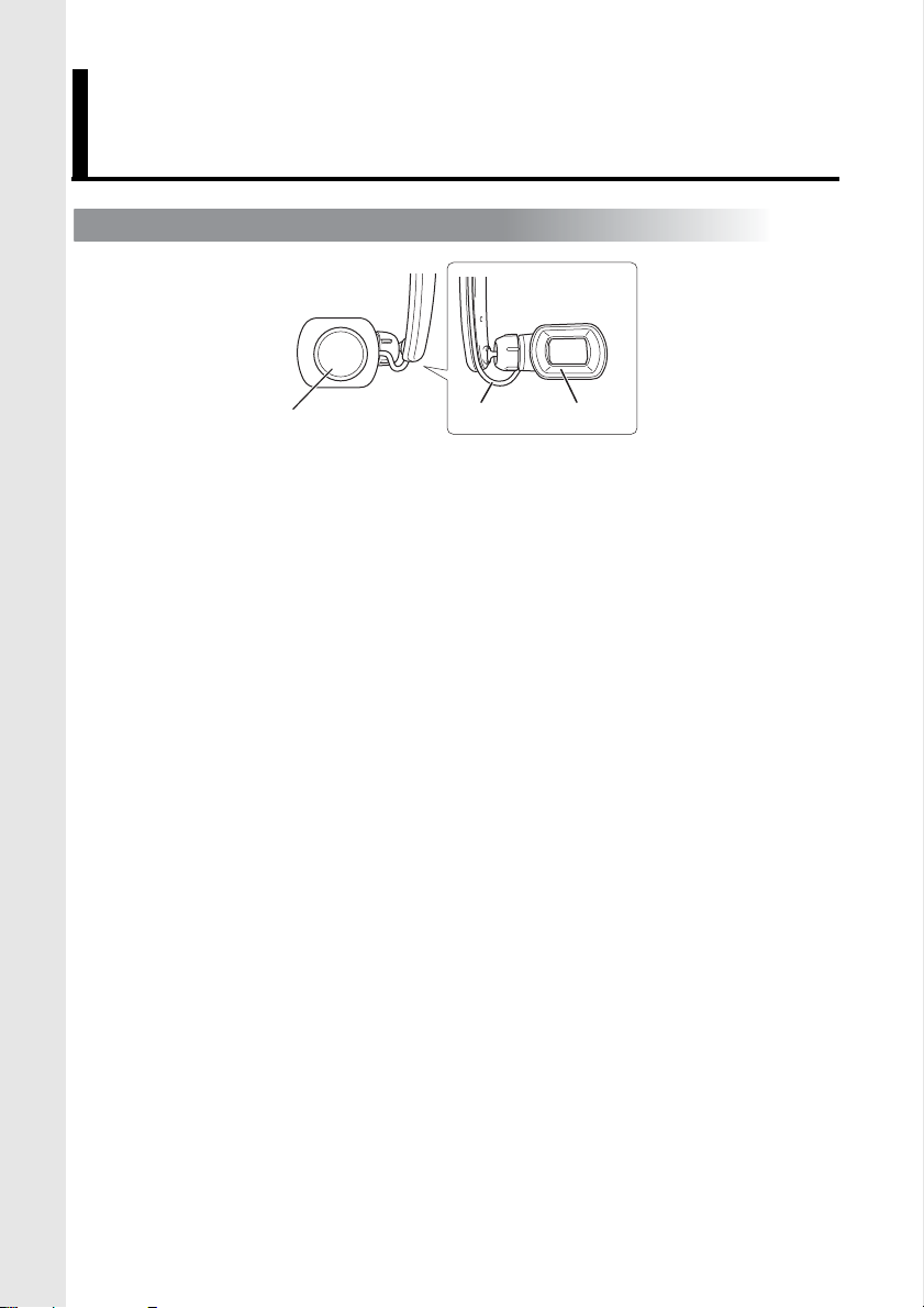
Names and functions of key components
Head Display
a
a Focus Adjustment Dial
Adjusts the focus of the image on the head display by
changing the focal length of the optics (from 30 cm to
infinity).
b Head Display Cable
Connects the head display to the control box and
transmits power and video signals to the head display.
c Eyecup
When attached, prevents the head display from touching
the user’s eye.
b
c
4
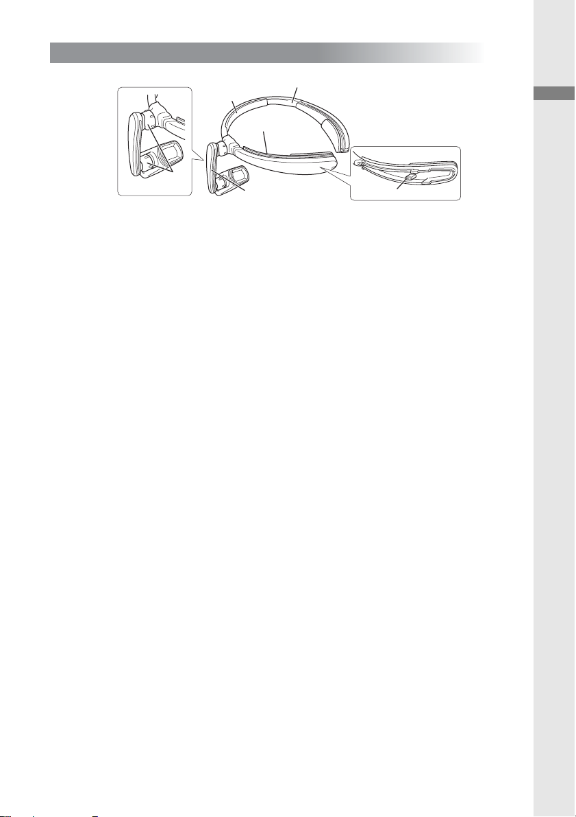
Harness
b
a
f
e
d
c
a Head Band
Attaches the AiRScouter to the user’s head and
distributes the weight of the unit.
b Forehead Pad
Cushions the head band and prevents it from slipping
down the user’s forehead.
c Cable Channel
Holds the head display cable in place along the head
band.
d Rear Band Attachment Post
Allows the user to attach the rear band and tighten the
head band around the head to prevent slippage.
Introduction
e Flexible Arm
Allows the user to adjust the position and angle of the
head display relative to the eye.
f Joint Dial
Loosens the ball joint to allow for adjustment of the
flexible arm, or tightens it to fix the flexible arm's position
and angle.
5
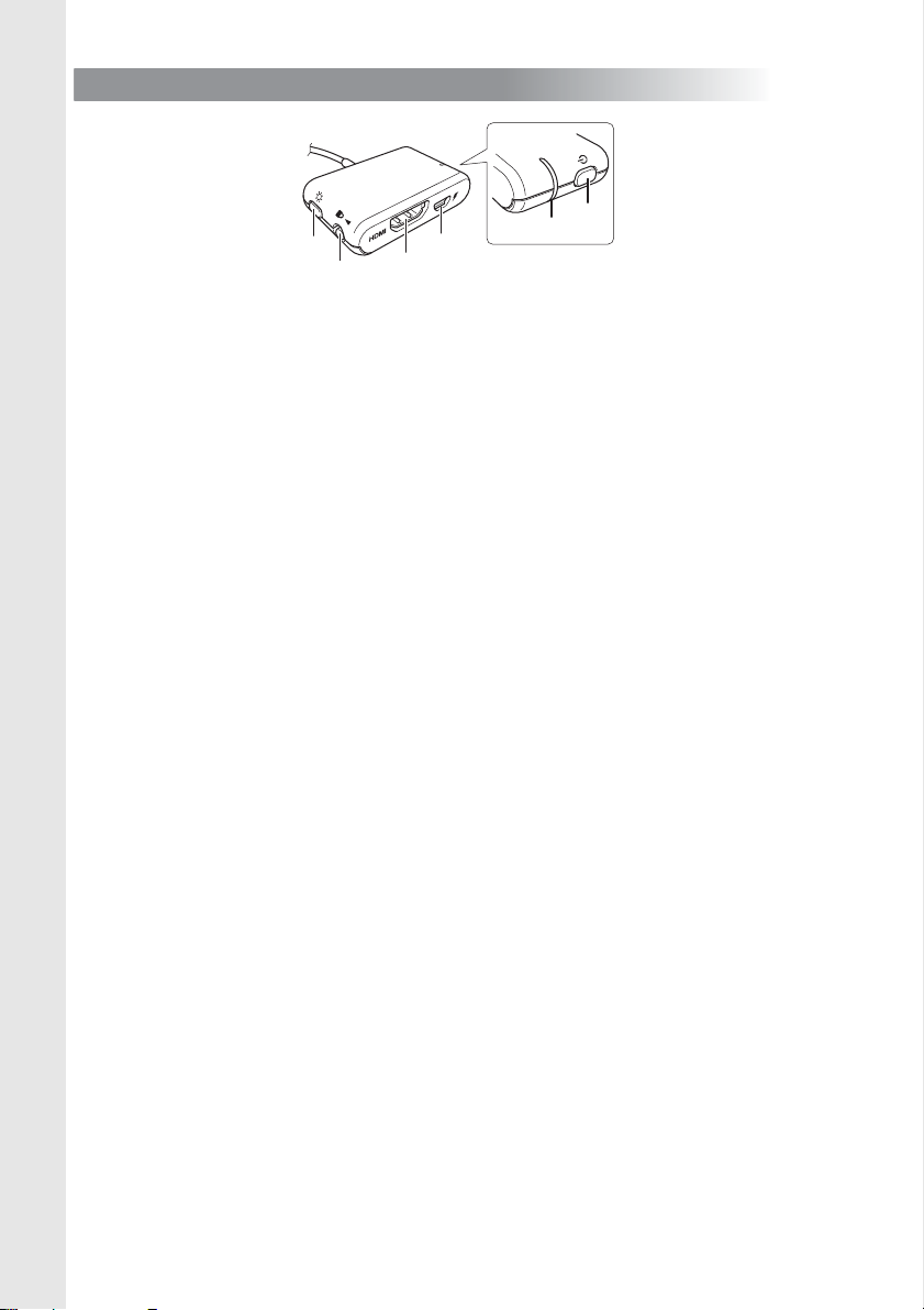
Control Box
a
b
c
e
d
f
a Power button
Press this button to power on the AiRScouter, and press
and hold it for two seconds to power off the AiRScouter.
b Brightness button
Press this button to select the next brightness level; note
that the AiRScouter has five levels of brightness.
Press and hold this button for two seconds to reduce the
size of image. To return to the normal size, press and
hold it again for two seconds.
c Key Lock switch
Slide the switch to the left to disable the power and
brightness buttons and prevent unintended changes
during operation. The key lock will also disable automatic
rotation of the image.
d HDMI
TM
input port
Allows the user to connect the control box to HDMIcompatible devices.
e Micro-USB B port
Allows the user to connect the control box to an external
power source such as a third-party USB battery.
f Display LED (Orange)
Lights up when the AiRScouter is on and an image is
being projected on the display.
6
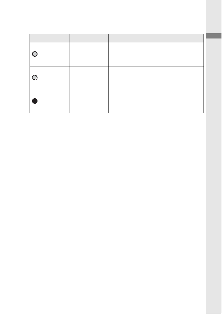
LED Indications
Display LED (Orange)
State Name Explanation
The AiRScouter is receiving a
(lit)
Display ON
compatible video signal from
an external device.
The AiRScouter is not
(flashing)
No input
receiving a compatible video
signal from an external device.
The AiRScouter is powered off.
(off)
Power OFF
To power it on, press the power
button.
Introduction
7
2.
1
2
3
Before using the AiRScouter
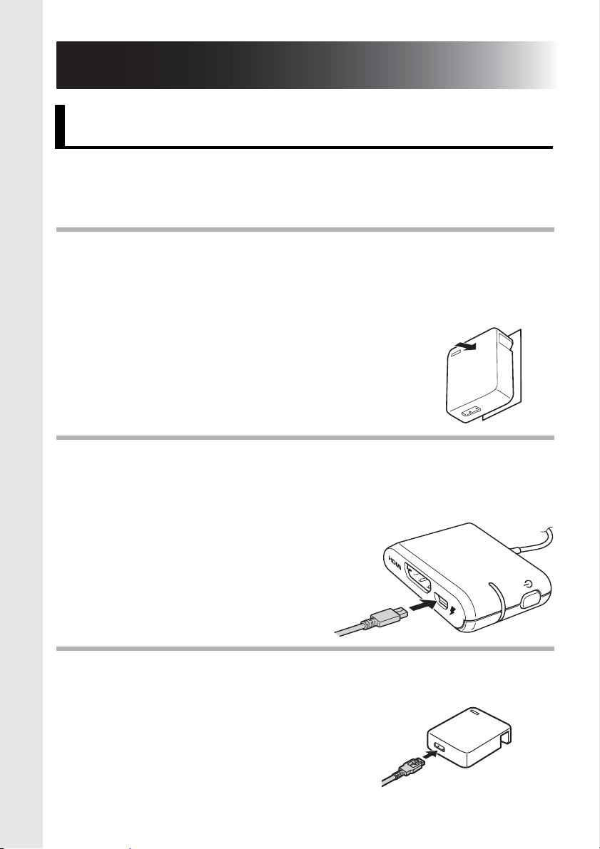
How to assemble the AiRScouter
The AiRScouter is powered by an external source, such as a
third party USB battery, that is connected to the micro-USB
port on the control box.
Before connecting an external battery to the control box,
ensure that the external battery has been fully charged.
(For more information on charging a third-party USB
battery, see the battery’s manual.)
Connect the Micro-USB B plug of a
USB Type-A to Micro-USB B cable to the Micro-USB B
port of the control box.
Connect the USB Type-A plug to the USB Type-A port of
the external battery.
8
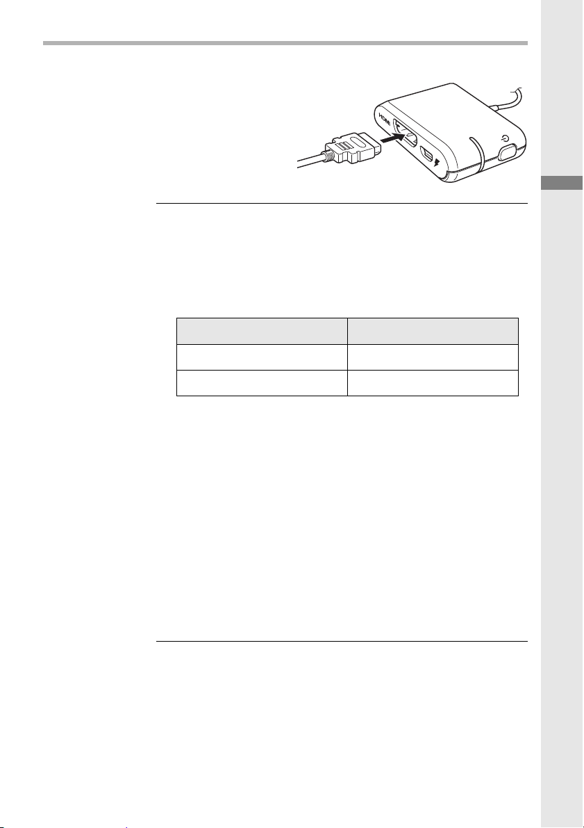
Connect the video input cable to the control box.
4
Capacity Battery Life
3,350 mAh Approx. 5 h
5,200 mAh Approx. 8 h
Before using the AiRScouter
Note
External third-party batteries, which can be
used to power the AiRScouter, may have
different capacities. Actual battery life will vary
depending on the battery type and
operational environment.
The only supported resolution for input
sources is 1280 x 720 (720p). If an input
source with a higher or unsupported
resolution is connected, the image may not
display correctly on the head display screen.
If this occurs, check the output resolution of
the video source.
Degradation of the video signal may occur
when longer input cables are used. For
maximum quality, it's recommended to use
HDMI and USB cables of 2 m length or
shorter.
9
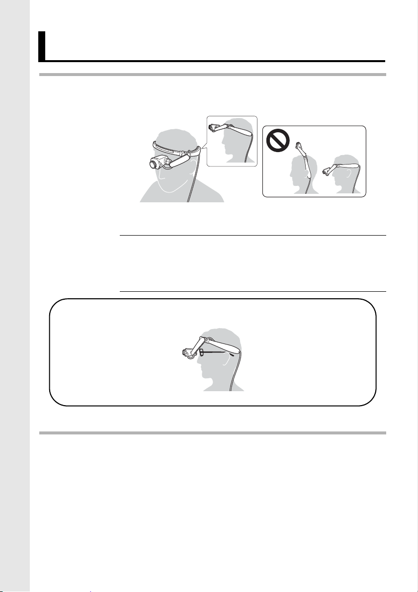
How to wear the AiRScouter
1
If you wear glasses
2
Place the head band onto the head as shown. The band
should be positioned just above the forehead.
Note
To secure the head display cable to your clothing, use the
cable clip.
If the head band feels loose or starts to slip down
the forehead, attach the rear band and use it to
tighten the fit on your head.
10
3. Adjusting the display
1
2
3
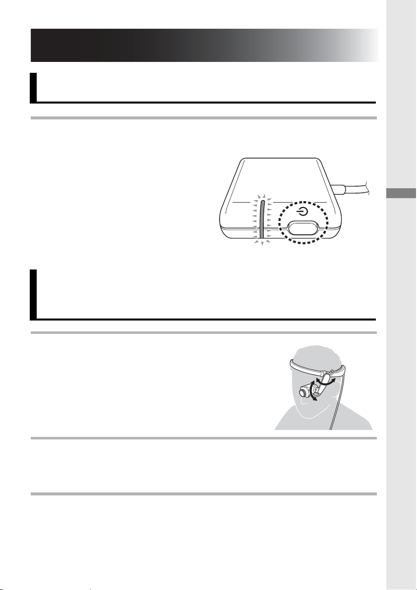
Turn the power on
Press the power button to turn the AiRScouter on. (The
LED will turn orange.)
Adjust the position of the Head Display
Adjusting the display
Loosen the ball joints by turning the
dials on either end of the flexible
arm counter-clockwise.
Adjust the position and angle of the head display so that it
is easy to view.
Tighten the ball joints by turning the dials on either end of
the flexible arm clockwise to fix the head display in place.
11
 Loading...