

Page 1
INSTRUCTION MANUAL
S-7250A
Please read this manual before using the machine.
Please keep this manual within easy reach for quick reference.
SINGLE NEEDLE DIRECT DRIVE LOCK STITCHER WITH
ELECTRONIC FEEDING SYSTEM AND THREAD TRIMMER
Page 2

Thank you very much for buying a BROTHER sewing machine. Before using your new machine,
please read the safety instructions and the explanations given in the instruction manual.
With industrial sewing machines, it is normal to carry out work while positioned directly in front of
moving parts such as the needle and thread take-up, and consequently there is always a danger of
injury that can be caused by these parts. Follow the instructions from training personnel and
instructors regarding safe and correct operation before operating the machine so that you will know
how to use it correctly.
S-7250A
Page 3
SAFETY INSTRUCTIONS
[1] Safety indications and their meanings
This instruction manual and the indications and symbols that are used on the machine itself are provided in order to ensure
safe operation of this machine and to prevent accidents and injury to yourself or other people.
The meanings of these indications and symbols are given below.
Indications
DANGER
CAUTION
Symbols
WARNING
· · · · ·
· · · · ·
· · · · ·
This symbol ( ) indicates something that you should be careful of. The picture inside the triangle
indicates the nature of the caution that must be taken.
(For example, the symbol at left means “beware of injury”.)
This symbol ( ) indicates something that you must not do.
This symbol ( ) indicates something that you must do. The picture inside the circle indicates the
nature of the thing that must be done.
(For example, the symbol at left means “you must make the ground connection”.)
The instructions which follow this term indicate situations where failure to follow the
instructions will result in death or serious injury.
The instructions which follow this term indicate situations where failure to follow the
instructions could result in death or serious injury.
The instructions which follow this term indicate situations where failure to follow the
instructions may result in minor or moderate injury.
S-7250A
i
Page 4
[2] Notes on safety
Wait at least 5 minutes after turning off the power switch and disconnecting the power cord from the wall outlet
before opening the cover of the control box. Touching areas where high voltages are present can result in severe
injury.
Do not allow any liquids to get onto this sewing machine, otherwise fire, electric shocks or operating problems may
occur.
If any liquid gets inside the sewing machine (machine head or control box), immediately turn off the power and
disconnect the power plug from the electrical outlet, and then contact the place of purchase or a qualified
technician.
DANGER
WARNING
CAUTION
Environmental requirements
Use the sewing machine in an area which is free
from sources of strong electrical noise such as
electrical line noise or static electric noise.
Sources of strong electrical noise may cause
problems with correct operation.
Any fluctuations in the power supply voltage
should be within 10% of the rated voltage for the
machine.
Voltage fluctuations which are greater than this
may cause problems with correct operation.
The power supply capacity should be greater than
the requirements for the sewing machine's power
consumption.
Insufficient power supply capacity may cause
problems with correct operation.
Machine installation should only be carried out by
a qualified technician.
Contact your Brother dealer or a qualified
electrician for any electrical work that may need to
be done.
The sewing machine weighs approximately 35 kg
(77lb). The installation should be carried out by
two or more people.
Do not connect the power cord until installation is
complete. The machine may operate if the treadle
is depressed by mistake, which could result in
injury.
Turn off the power switch before inserting or
removing the plug, otherwise damage to the
control box could result.
Be sure to connect the ground. If the ground
connection is not secure, you run a high risk of
receiving a serious electric shock, and problems
with correct operation may also occur.
When securing the cords, do not bend the cords
excessively or fasten them too hard with staples,
otherwise there is the danger that fire or electric
shocks could occur.
Installation
The ambient temperature should be within the
range of 5C to 35C during use.
Temperatures which are lower or higher than this
may cause problems with correct operation.
The relative humidity should be within the range of
45% to 85% during use, and no dew formation
should occur in any devices.
Excessively dry or humid environments and dew
formation may cause problems with correct
operation.
In the event of an electrical storm, turn off the power
and disconnect the power cord from the wall outlet.
Lightning may cause problems with correct
operation.
Do not connect anything to the USB port other than
the USB memory. If this is not observed, problems
with operation may result.
If using a work table which has casters, the casters
should be secured in such a way so that they
cannot move.
Secure the table so that it will not move when tilting
back the machine head. If the table moves, it may
crush your feet or cause other injuries.
Use both hands to hold the machine head when
tilting it back or returning it to its original position. If
only one hand is used, the weight of the machine
head may cause your hand to slip, and your hand
may get caught.
Be sure to wear protective goggles and gloves
when handling the lubricating oil and grease, so that
they do not get into your eyes or onto your skin,
otherwise inflammation can result.
Furthermore, do not drink the oil or eat the grease
under any circumstances, as they can cause
vomiting and diarrhea.
Keep the oil out of the reach of children.
ii
S-7250A
Page 5
This sewing machine should only be used by
operators who have received the necessary training
in safe use beforehand.
The sewing machine should not be used for any
applications other than sewing.
Be sure to wear protective goggles when using the
machine.
If goggles are not worn, there is the danger that if a
needle breaks, parts of the broken needle may enter
your eyes and injury may result.
Turn off the power switch at the following times.
The machine may operate if the treadle is
depressed by mistake, which could result in injury.
When threading the needle
When replacing the bobbin and needle
When not using the machine and when leaving
the machine unattended
If using a work table which has casters, the casters
should be secured in such a way so that they
cannot move.
CAUTION
Sewing
Attach all safety devices before using the sewing
machine. If the machine is used without these
devices attached, injury may result.
Do not touch any of the moving parts or press any
objects against the machine while sewing, as this
may result in personal injury or damage to the
machine.
Secure the table so that it will not move when tilting
back the machine head. If the table moves, it may
crush your feet or cause other injuries.
Use both hands to hold the machine head when
tilting it back or returning it to its original position. If
only one hand is used, the weight of the machine
head may cause your hand to slip, and your hand
may get caught.
If an error occurs in machine operation, or if
abnormal noises or smells are noticed, immediately
turn off the power switch. Then contact your nearest
Brother dealer or a qualified technician.
If the machine develops a problem, contact your
nearest Brother dealer or a qualified technician.
Cleaning
Turn off the power switch before carrying out
cleaning. The machine may operate if the treadle is
depressed by mistake, which could result in injury.
Secure the table so that it will not move when tilting
back the machine head. If the table moves, it may
crush your feet or cause other injuries.
Use both hands to hold the machine head when
tilting it back or returning it to its original position. If
only one hand is used, the weight of the machine
head may cause your hand to slip, and your hand
may get caught.
Maintenance and inspection
Maintenance and inspection of the sewing machine
should only be carried out by a qualified technician.
Ask your Brother dealer or a qualified electrician to
carry out any maintenance and inspection of the
electrical system.
Turn off the power switch and disconnect the power
cord from the wall outlet at the following times,
otherwise the machine may operate if the treadle is
depressed by mistake, which could result in injury.
When carrying out inspection, adjustment and
maintenance
When replacing consumable parts such as the
rotary hook and knife
Always be sure to turn off the power switch and then
wait one minute before opening the pulley cover. If
you touch the surface of the motor, it may cause
burns.
If the power switch needs to be left on when carrying
out some adjustment, make sure that you switch the
sewing machine to maintenance mode. Pay careful
attention to safety.
Be sure to wear protective goggles and gloves when
handling the lubricating oil and grease, so that they
do not get into your eyes or onto your skin,
otherwise inflammation can result.
Furthermore, do not drink the oil or eat the grease
under any circumstances, as they can cause
vomiting and diarrhea.
Keep the oil out of the reach of children.
Secure the table so that it will not move when tilting
back the machine head. If the table moves, it may
crush your feet or cause other injuries.
Use both hands to hold the machine head when
tilting it back or returning it to its original position.
If only one hand is used, the weight of the machine
head may cause your hand to slip, and your hand
may get caught.
When replacing parts and installing optional
accessories, be sure to use only genuine Brother
parts.
Brother will not be held responsible for any
accidents or problems resulting from the use of
non-genuine parts.
If any safety devices have been removed, be
absolutely sure to re-install them to their original
positions and check that they operate correctly
before using the machine.
To prevent accidents and problems, do not modify
the machine yourself.
Brother will not be held responsible for any
accidents or problems resulting from modifications
made to the machine.
S-7250A
iii
Page 6
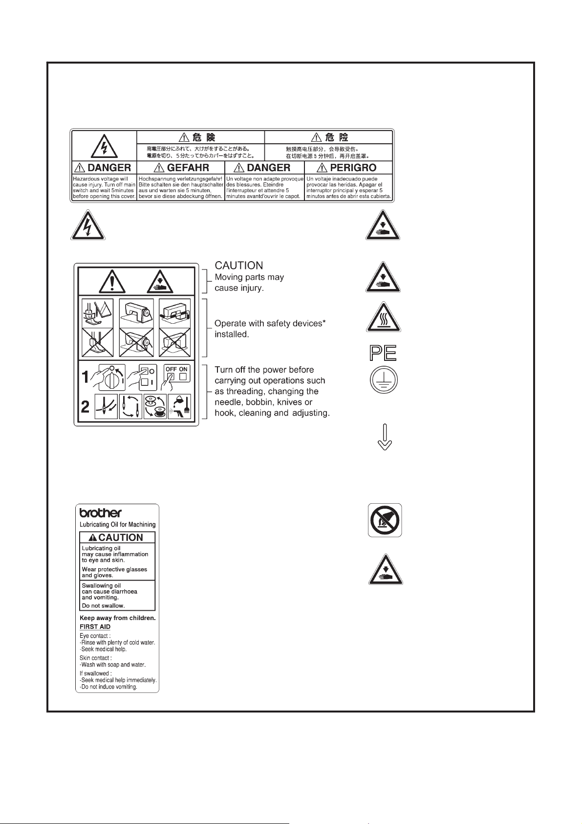
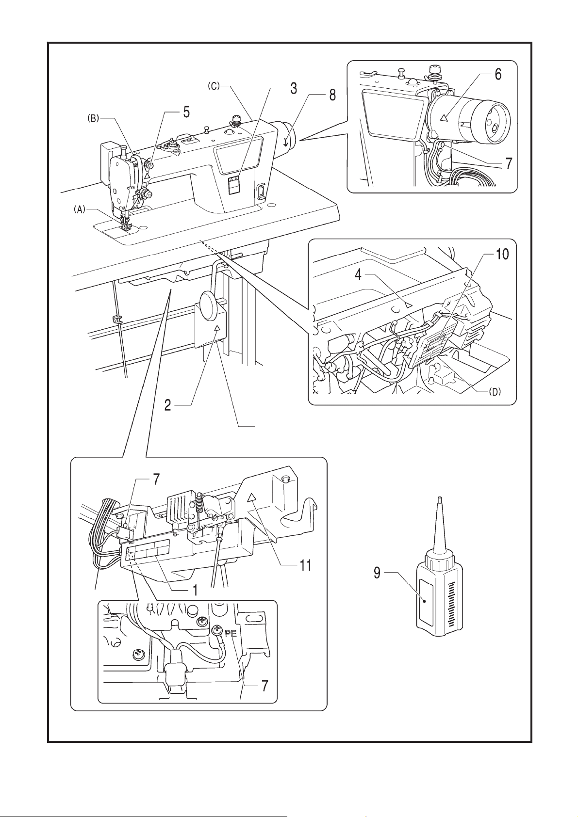
[3] Warning labels
The following warning labels appear on the sewing machine.
Please follow the instructions on the labels at all times when using the machine. If the labels have been removed or are
difficult to read, please contact your nearest Brother dealer.
1
2
3
* Safety devices: (A) Finger guard
Touching areas where high voltages are present can
result in severe injury. Turn off the power before
opening the cover.
(B) Thread take-up cover
(C) Motor cover
(D) Pulse motor cover
9
4
5
6
7
8
10
Be careful not to get your
hands caught when returning
the machine head to its
original position after it has
been tilted.
Be careful to avoid injury from
the moving thread take-up.
High temperature warning
display
Be sure to connect the ground.
If the ground connection is not
secure, you run a high risk of
receiving a serious electric
shock, and problems with
correct operation may also
occur.
Direction of operation
Do not hold. Problems with
operation or injury may
occur.
iv
S-7250A
11
Do not place your hands
inside the bottom cover.
Problems with operation or
injury may occur.
Page 7
Transformer box
(100V/110V/380V/400V)
Oil tank
S-7250A
1460D
v
Page 8

CONTENTS
1. MACHINE SPECIFICATIONS ............... 1
2. INSTALLATION ..................................... 2
2-1. Table processing diagram ................................ 3
2-2. Installation ........................................................ 3
2-3. Lubrication ........................................................ 6
2-4. Connecting the cords ........................................ 7
2-4-1. Connecting the cords ............................. 7
2-4-2. Other cords ............................................ 9
3. USING THE OPERATION PANEL
(BASIC OPERATIONS) ........................ 13
3-1. Names and functions ...................................... 13
3-2. Sewing start and end backtack stitches ......... 15
3-3. Sewing continuous backtack stitches ............. 16
4. USING THE OPERATION PANEL
(ADVANCED OPERATIONS) .............. 17
4-1. Sewing pitch setting method .......................... 17
4-2. Switching the 4-digit display ........................... 18
4-3. Setting the sewing speed ............................... 18
4-3-1. Setting the maximum sewing speed .... 18
4-3-2. Backtack sewing speed setting
method ................................................. 19
4-4. Setting the counters ........................................ 20
4-4-1. Lower thread counter ........................... 20
4-4-2. Production counter ............................... 21
4-4-3. Needle replacement counter ................ 22
4-5. Sewing locus setting meth .............................. 23
4-6. Setting basic functions .................................... 24
4-6-1. Changing the needle stop position ...... 25
4-6-2. Thread trimming disable ...................... 26
4-6-3. Thread wiping ...................................... 27
4-6-4. Correction sewing ................................ 28
4-6-5. Slow start ............................................. 29
4-6-6. Setting the illumination LED light ......... 30
4-6-7.
Setting lower thread counter operation
4-6-8. Prev. thread away ................................ 32
4-6-9. Short trailing thread .............................. 33
4-6-10. Correction sewing function (1) ........... 34
4-6-11. Correction sewing function (2) ........... 35
4-7. Memory switch setting method ....................... 36
4-8. List of memory switch settings ....................... 37
4-9. Reading and writing data using USB media ... 41
4-10. Resetting all settings to their defaults ........... 42
4-11. Hand switch .................................................. 43
4-11-1. Hand switch function setting .............. 45
4-11-2. 2nd correction pitch setting ................ 46
4-11-3. 2nd pitch setting ................................. 46
. 31
4-11-4. Menu numbers for setting functions for
the hand switch .................................. 46
5. CLEANING ........................................... 47
6. STANDARD ADJUSTMENTS .............. 48
6-1. Arm thread guide R ......................................... 48
6-2. Presser foot height .......................................... 49
6-3. Adjusting the feed dog height ......................... 50
6-4. Adjusting the feed dog angle .......................... 51
6-5. Adjusting the needle bar height ...................... 51
6-6. Adjusting the needle and feed mechanism
timing ............................................................... 52
6-7. Needle and rotary hook timing ........................ 53
6-8. ADJUSTING THE ROTARY HOOK
LUBRICATION AMOUNT ............................... 54
6-9. Thread trimming (Other than short trailing thread
specifications) ................................................. 55
6-10. Thread trimming (Short trailing thread
specifications) ............................................... 58
7. TROUBLESHOOTING .......................... 61
7-1. Sewing ............................................................ 61
7-2. Error code displays ......................................... 68
8. 7-SEGMENT DISPLAY ......................... 72
S-7250A
Page 9

S-7250A
Page 10
1. MACHINE SPECIFICATIONS
1. MACHINE SPECIFICATIONS
Thread wiper
1424D
Specifications Short trailing thread specifications
Use For medium-weight materials For heavy-weight materials
Max. sewing speed
* Standard feed locus
Sewing speed at the time of shipment 4,000 sti/min
Backtack sewing speed
* Standard feed locus
Max. stitch length 5 mm 5 mm (can be set to 7 mm)
Presser foot
height
Feed dog height 0.8 mm 1.2 mm
Needle (DB×1, DP×5) #11 - #18 #19 - #22
Motor AC servo motor
Control circuit Microprocessor
Lifting lever 6 mm
Knee lifter 13 mm
Stitch length 2.0 mm or less/
Automatic 150 (*1) - 3000 sti/min, Manual 150 (*1) - 4000 sti/min*
3 5
5,000 sti/min
(*1) Inching setting speed
3 4
P
4,000 sti/min
O
1
S-7250A
Page 11
2. INSTALLATION
CAUTION
Machine installation should only be carried out by a
qualified technician.
Contact your Brother dealer or a qualified electrician
for any electrical work that may need to be done.
The sewing machine weighs approximately 35 kg
(77lb). The installation should be carried out by two
or more people.
Do not connect the power cord until installation is
complete.
The machine may operate if the treadle is
depressed by mistake, which could result in injury.
About the machine set-up location
・ Do not set up this sewing machine near other equipment such as
televisions, radios or cordless telephones, otherwise such
equipment may be affected by electronic interference from the
sewing machine.
・ The sewing machine should be plugged directly into an AC wall
outlet. Operation problems may result if extension cords are
used.
2. INSTALLATION
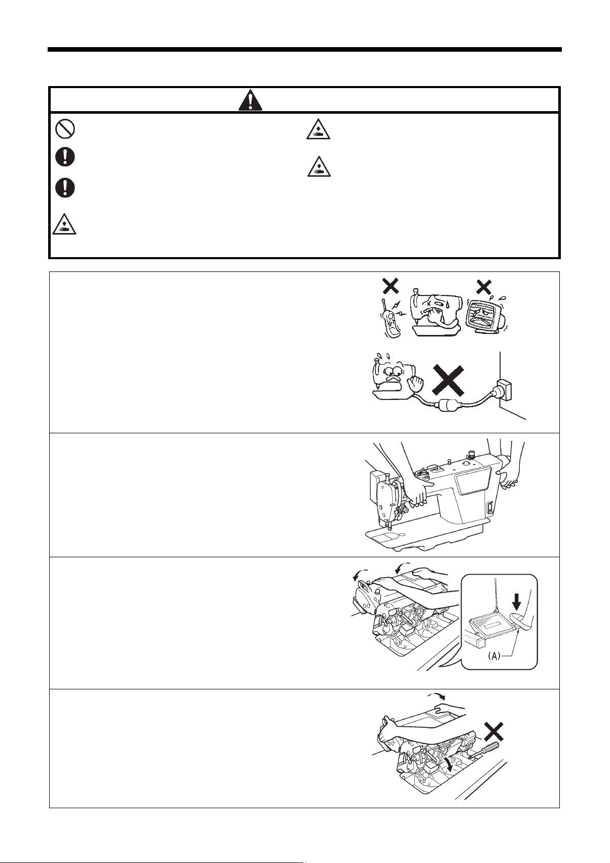
Secure the table so that it will not move when tilting
back the machine head. If the table moves, it may
crush your feet or cause other injuries.
Use both hands to hold the machine head when
tilting it back or returning it to its original position.
If only one hand is used, the weight of the machine
head may cause your hand to slip, and your hand
may get caught.
0475D
Carrying the machine
・ The sewing machine should be carried by the arm and the motor
cover by two people as shown in the illustration.
* Do not hold by any part other than the motor cover. If this is not
observed, it may result in damage to the sewing machine.
Tilting back the machine head
・ Hold section (A) with your foot so that the table does not move,
and then push the arm with both hands to tilt back the machine
head.
Returning the machine head to the upright position
1. Clear away any tools, etc. which may be near the table holes.
2. While holding the face plate with your left hand, gently return the
machine head to the upright position with your right hand.
1341D
1342D
1343D
S-7250A
2
Page 12
2. INSTALLATION
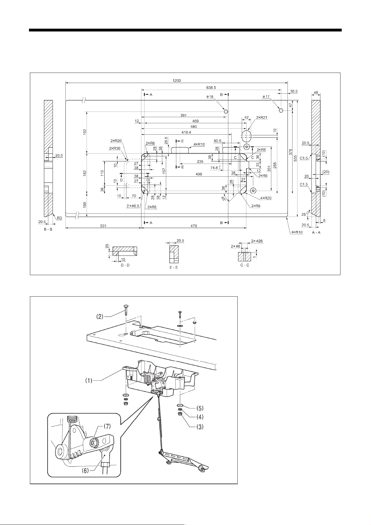
2-1. Table processing diagram
・ The top of the table should be 40 mm in thickness and should be strong enough to hold the weight and withstand the
vibration of the sewing machine.
・ Drill holes as indicated in the illustration below.
Head rest hole
Cotton stand hole
Cord hole
Control box
mounting hole
Control box
mounting hole
1412D
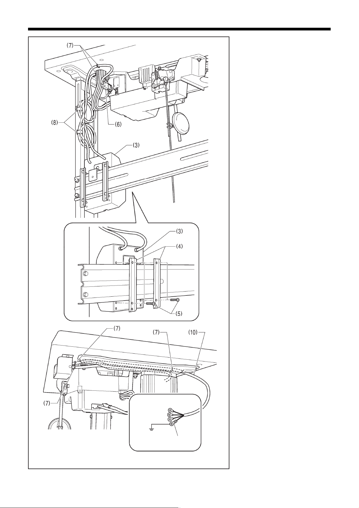
2-2. Installation
1. Control box + Oil pan
(1) Control box
(2) Bolts [4 pcs]
(3) Nuts [4 pcs]
(4) Spring washers [4 pcs]
(5) Washers [4 pcs]
2. Connecting rod
(6) Connecting rod
(7) Nut
3
S-7250A
Page 13
2. INSTALLATION
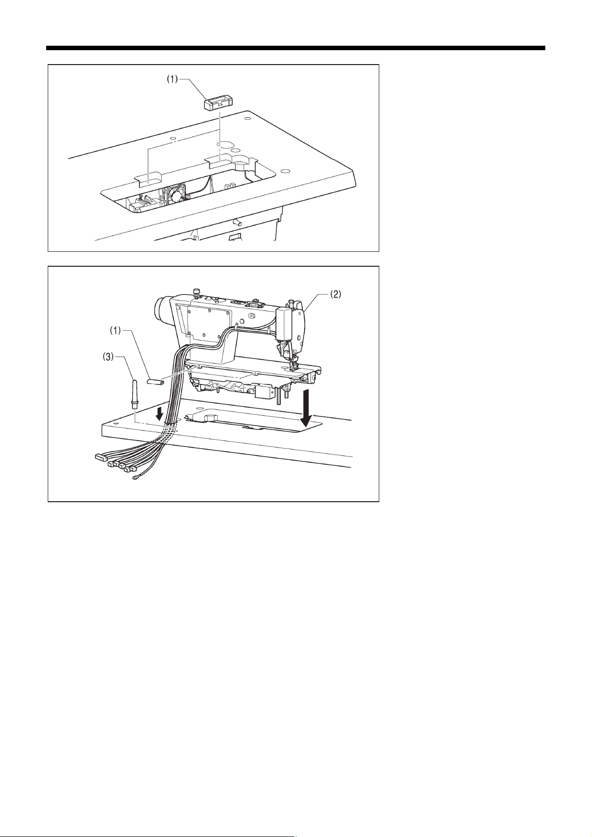
3. Rubber cushions
(1) Rubber cushions [2 pcs]
1414D
4. Machine head
(1) Hinges [2 pcs]
(2) Machine head
(3) Head rest
NOTE:
・ Bind the cords together and pass
them through the cord hole.
・ Tap the head rest (3) securely into
the table hole.
・ If the head rest (3) is not pushed in
as far as it will go, the machine head
will not be sufficiently stable when it
is tilted back.
1415D
S-7250A
4
Page 14
2. INSTALLATION
10mm
5
1416D
Within 13 mm
1417D
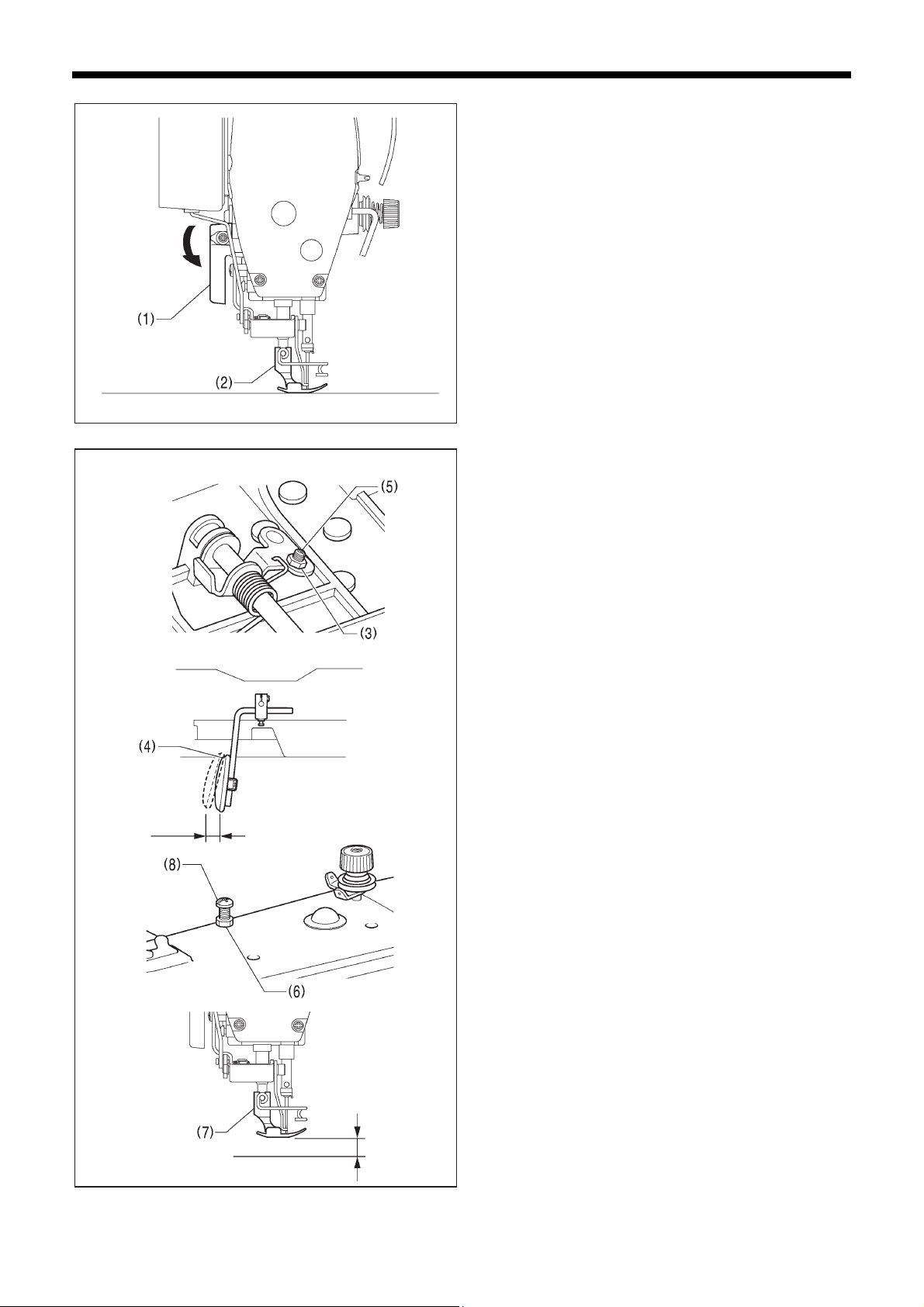
5. Knee lifter plate
<Knee lifter adjustment>
1. Turn the machine pulley so that the feed dog is below the
top of the needle plate.
2. Lower the presser foot (1) by using the lifting lever (2).
3. Loosen the nut (3).
4. Turn the screw (5) to adjust so that the amount of play in
the knee lifter plate (4) is approximately 10 mm.
5. After adjustment is completed, securely tighten the nut
(3).
6. Loosen the nut (6).
7. Turn the adjusting screw (8) to adjust so that the presser
foot (7) is at the desired position within a distance of 13
mm from the needle plate when the knee lifter plate is
fully pressed.
8. After adjustment is completed, securely tighten the nut
(6).
S-7250A
Page 15
2-3. Lubrication
Do not connect the power cord until lubrication has been completed, otherwise the machine may operate if the
treadle is depressed by mistake, which could result in injury.
Be sure to wear protective goggles and gloves when handling the lubricating oil, so that it does not get into your
eyes or onto your skin.
If care is not taken, inflammation can result. Furthermore, do not drink the lubricating oil. Diarrhea or vomiting may
result.
Keep the oil out of the reach of children.
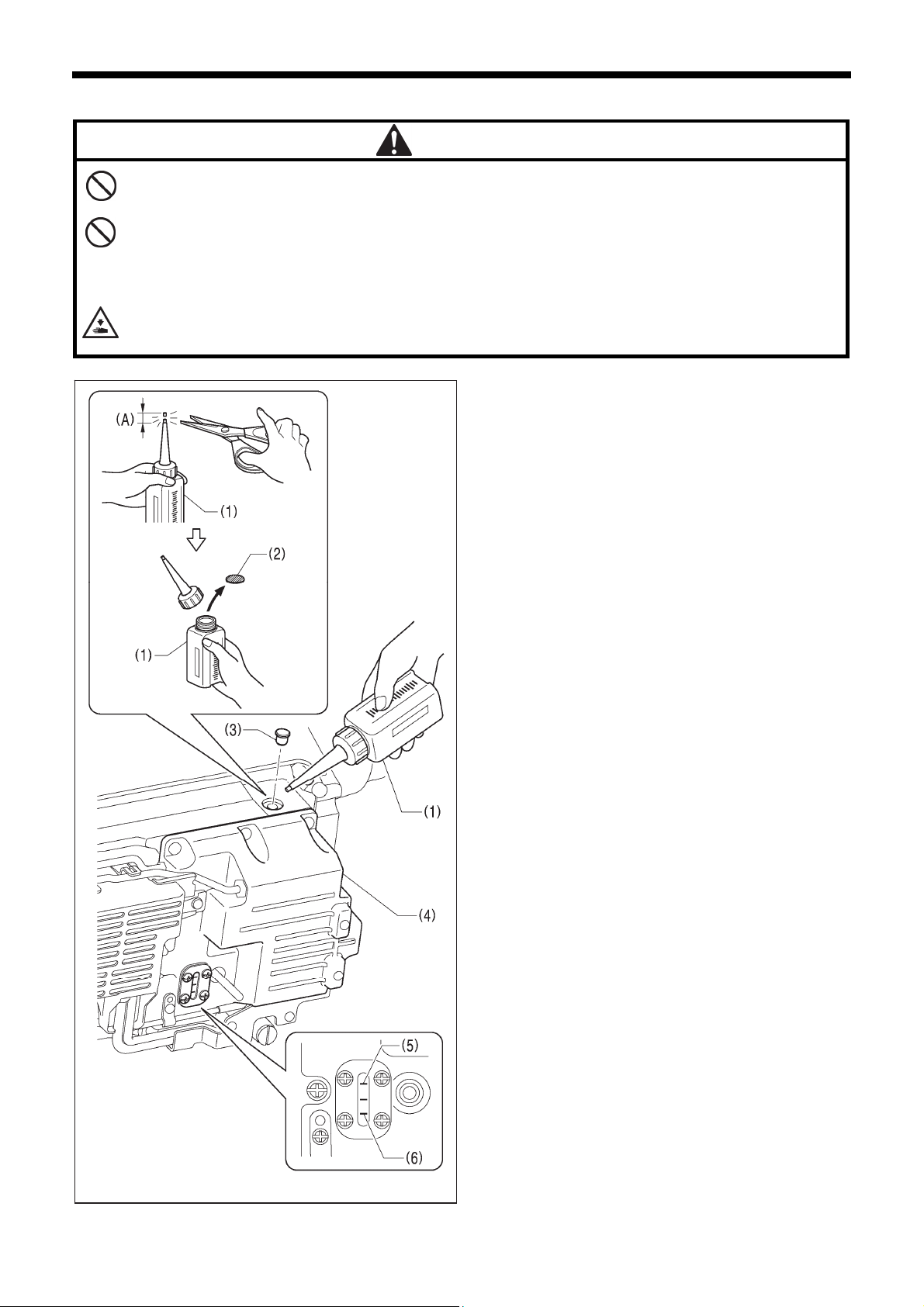
When cutting the nozzle of the oil tank, hold the base of the nozzle securely.
If you hold the end of the nozzle, injury from the scissors may result.
2. INSTALLATION
CAUTION
The sewing machine should always be lubricated and the oil
supply replenished before it is used for the first time, and also
after long periods of non-use.
1. Hold the base of the nozzle of the accessory oil tank (1),
and use scissors to cut about half-way along the straight
section (A) of the nozzle.
2. Loosen and remove the nozzle, and then remove the seal
(2).
3. Tighten the nozzle.
4. Tilt back the machine head.
5. Remove the rubber cap (3), and pour lubricating oil into
the oil cover (4) until it reaches the upper reference line
(5).
6. Replace the rubber cap (3).
7. Return the machine head to its original position.
NOTE:
When the machine head is tilted back at times such as the
following, lubricating oil may leak out from the oil cover (4).
1) If lubricating oil is added until the oil level goes above
the upper reference line (5) on the oil cover (4).
<Lubrication oil replenishment interval>
If the oil level drops below the lower reference line (6) on the
oil cover (4), be sure to replenish the oil.
Upper
reference line
Lower
reference line
1418D
S-7250A
6
Page 16
2. INSTALLATION
2-4. Connecting the cords
Contact your Brother dealer or a qualified electrician for any electrical work that may need to be done.
Do not connect the power cord until all cords have been connected.
The machine may operate if the treadle is depressed by mistake, which could result in injury.
When securing the cords, do not bend the cords excessively or fasten them too hard with staples, otherwise there is
the danger that fire or electric shocks could occur.
Be sure to connect the ground. If the ground connection is not secure, you run a high risk of receiving a serious
electric shock, and problems with correct operation may also occur.
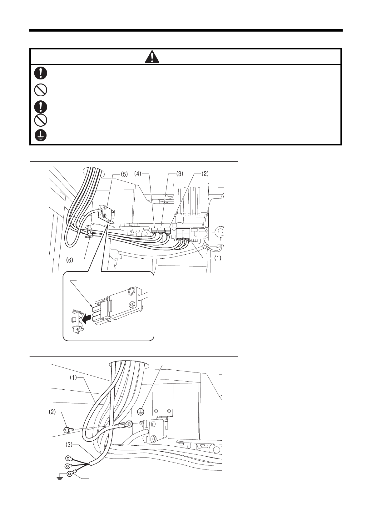
2-4-1. Connecting the cords
Align the flat edges
CAUTION
Ground symbol
1419D
1. Cor ds ( 1)
(1) Solenoid connector 14-pin
(2) Sewing machine motor encoder
connector 10-pin
(3) Feed motor encoder connector
6-pin
(4) Operation panel connector 5-pin
(5) Power connector 3-pin
1. Secure the cords to the control box
with the black band (6).
NOTE:
For Europe specifications, Americas
220 V specifications and 100 V/400
V system specifications, refer to
“2-4-2. Other cords”.
2. Ground wire
(1) Ground wire
(2)
Screw
(3) Power cord
1. Attach an appropriate plug to the
power cord (3).
(The green and yellow wire is the
ground wire.)
2. Insert the power plug into a
properly-grounded electrical outlet.
7
Green and yellow wire (ground wire)
S-7250A
1420D
NOTE:
・ Make sure that the ground
connections are secure in order to
ensure safety.
・ For Europe specifications, Americas
220 V specifications and 100 V/400
V system specifications, refer to
“2-4-2. Other cords”.
Page 17
2. INSTALLATION
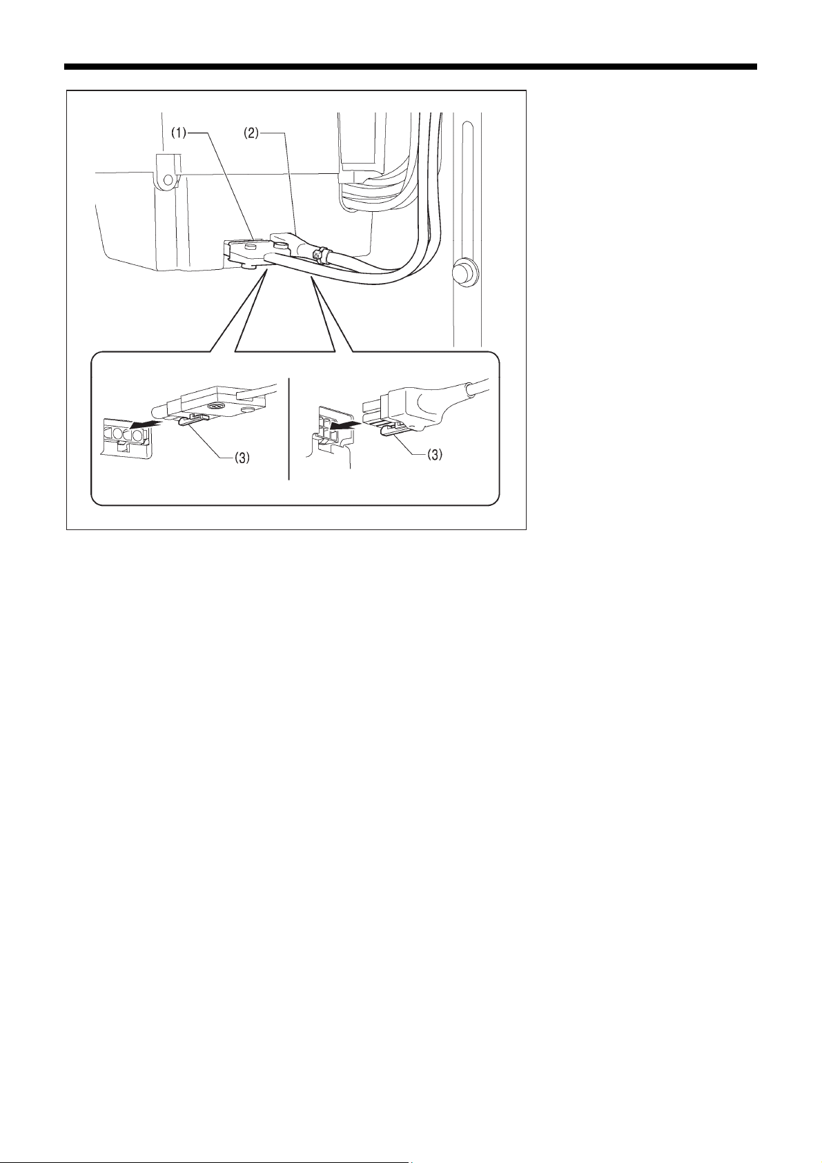
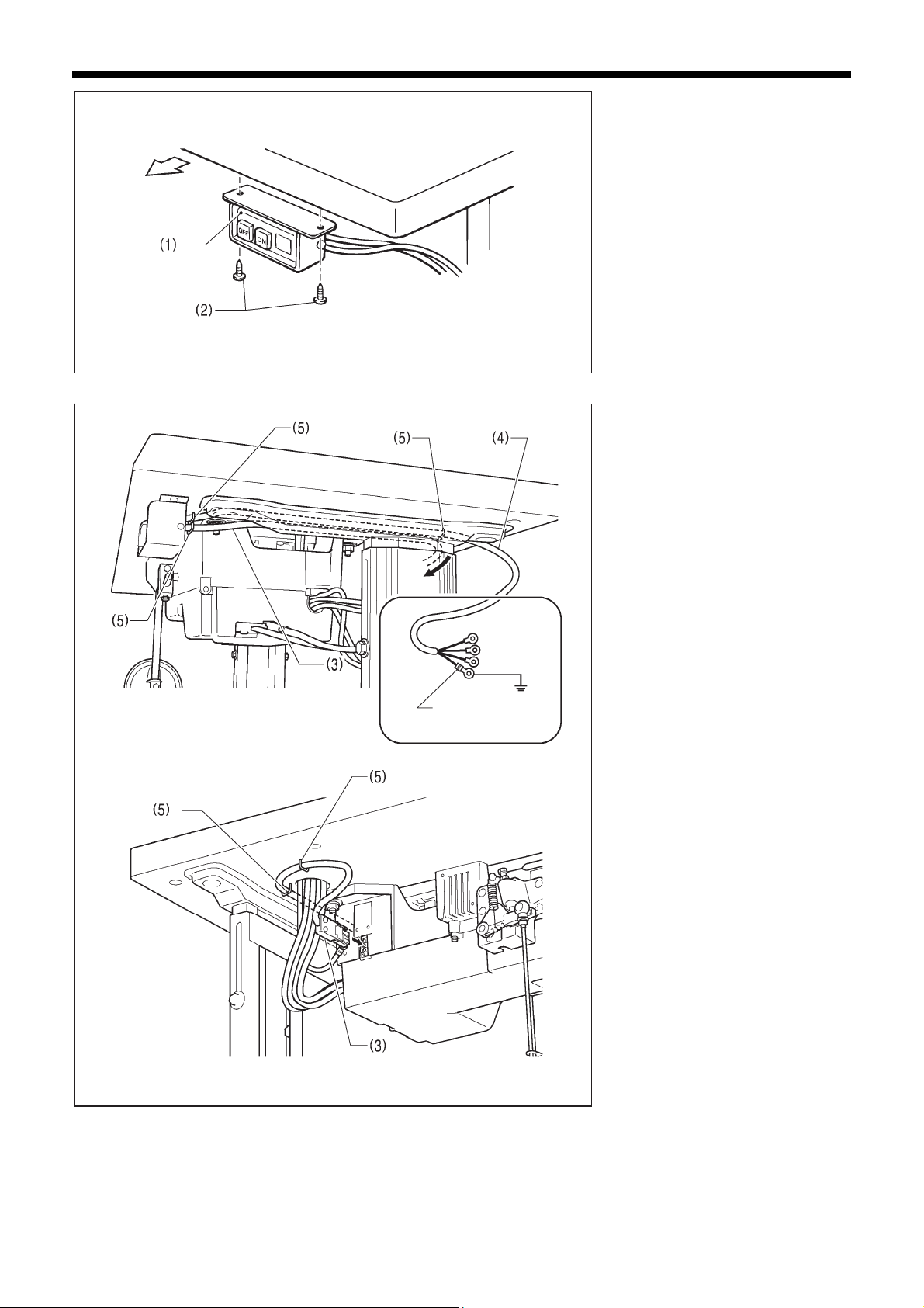
3. Cords (2)
(1) Machine motor connector 4-pin
(2) Feed motor connector 6-pin
Lower the tab (3).
Push in securely until the tabs (3) engage.
1421D
S-7250A
8
Page 18
2. INSTALLATION
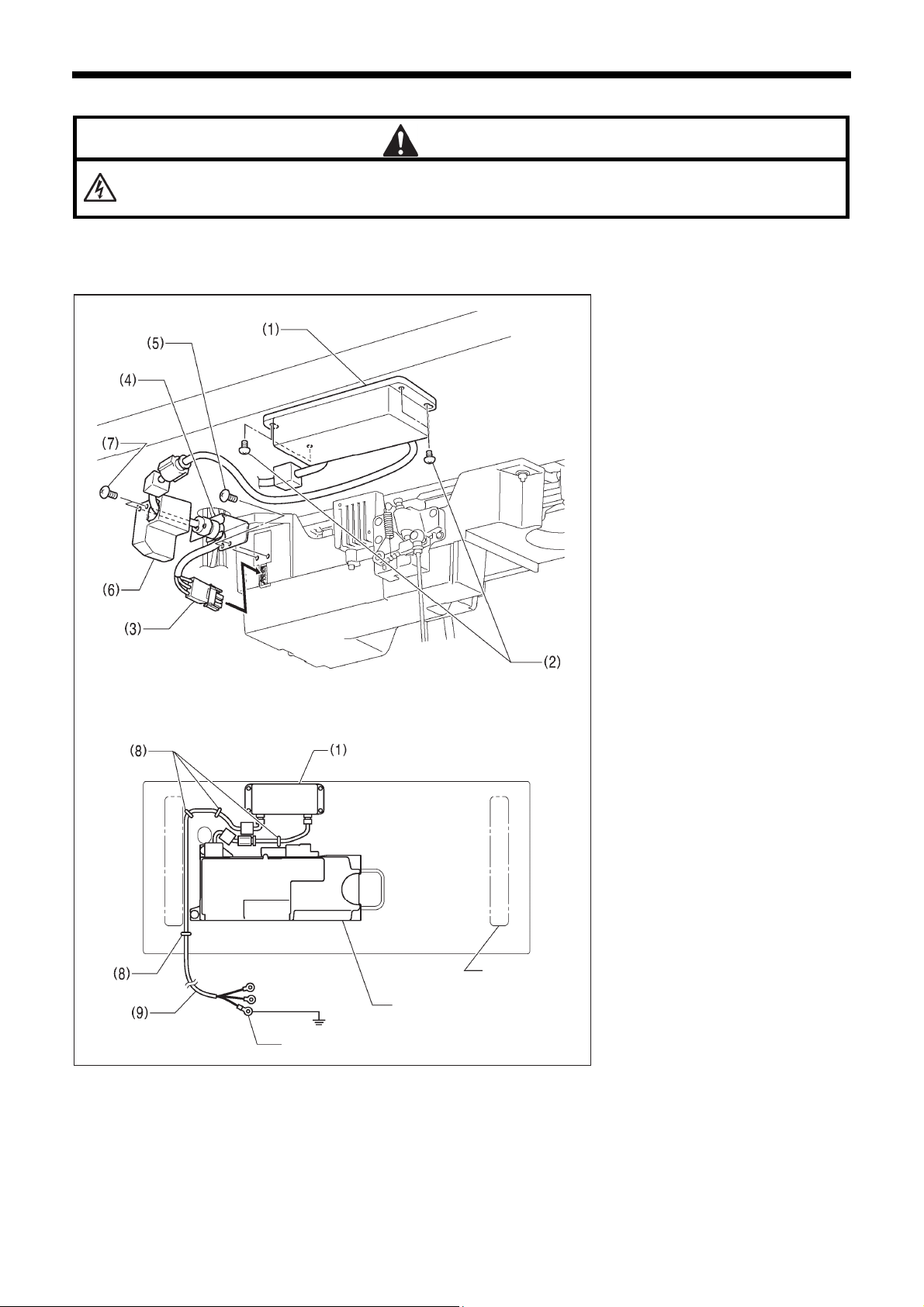
2-4-2. Other cords
DANGER
Wait at least 5 minutes after turning off the power switch and disconnecting the power cord from the wall outlet
before opening the cover of the control box. Touching areas where high voltages are present can result in severe
injury.
For Europe specifications, Americas 220 V specifications and 100 V/400 V system specifications, connect the cords
according to the respective specifications.
<Europe specifications>
(1) Filter box
(2) Screws [4 pcs]
(3) Connector
(4) CE bush plate
(5) Screws [2 pcs]
(6) CE D cord cover
(7) Screws [2 pcs]
(8) Staples [4 pcs]
(9) Power cord
1. Attach an appropriate plug to the
power cord (9). (The green and
yellow wire is the ground wire.)
2. Insert the power plug into a
properly-grounded electrical outlet.
<Seen from underneath table>
NOTE:
・ Take care when tapping in the
staples (8) to make sure that they do
not pierce the cords.
・ Do not use extension cords,
otherwise machine operation
problems may result.
Leg
Control box
Green and yellow wire (ground wire)
1480D
9
S-7250A
Page 19
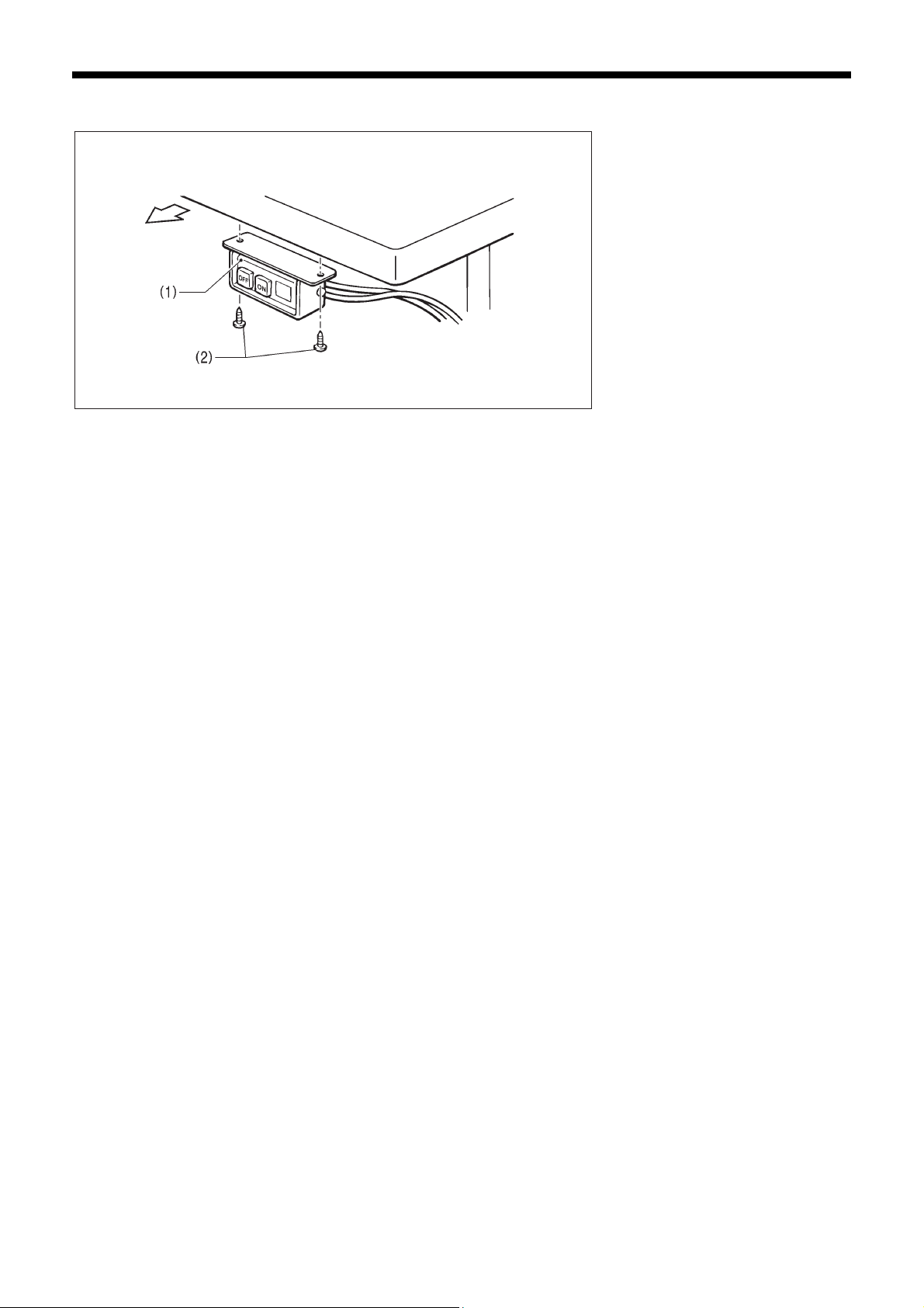
For Europe specifications, Americas 220 V specifications and 100 V/400 V system specifications, connect the cords
according to the respective specifications.
<For 100 V/400 V system
specifications>
(1) Power switch
(2) Screws [2 pcs]
2. INSTALLATION
Operator
4145M
S-7250A
10
Page 20
2. INSTALLATION
(3) Transformer box
(4) Transformer box plates [2 pcs]
(5) Screws [with washer] [4 pcs]
(6) Power supply connector 3-pin
(7) Staples [5 pcs]
(8) Cord clamps [2 pcs]
(9) Power cord
1. Attach an appropriate plug to the
power cord (10).
(The green and yellow wire is the
ground wire.)
2. Insert the power plug into a
properly-grounded electrical outlet.
NOTE:
・ Take care when tapping in the
staples (7) to make sure that they do
not pierce the cords.
・ Do not use extension cords,
otherwise machine operation
problems may result.
11
Green and yellow wire
(ground wire)
1479D
S-7250A
Page 21
2. INSTALLATION
<For Americas 220 V
specifications>
(1) Power switch
(2) Screws [2 pcs]
Operator
4145M
(3) Power supply connector 3-pin
(4) Power cord
(5) Staples [5 pcs]
1. Attach an appropriate plug to the
power cord (4).
(The green and yellow wire is the
ground wire.)
2. Insert the power plug into a
properly-grounded electrical outlet.
Green and yellow
wire (ground wire)
NOTE:
・ Take care when tapping in the
staples (5) to make sure that they do
not pierce the cords.
・ Do not use extension cords,
otherwise machine operation
problems may result.
S-7250A
1423D
12
Page 22
3. USING THE OPERATION PANEL (BASIC OPERATIONS)
3.
USING THE OPERATION PANEL (BASIC OPERATIONS)
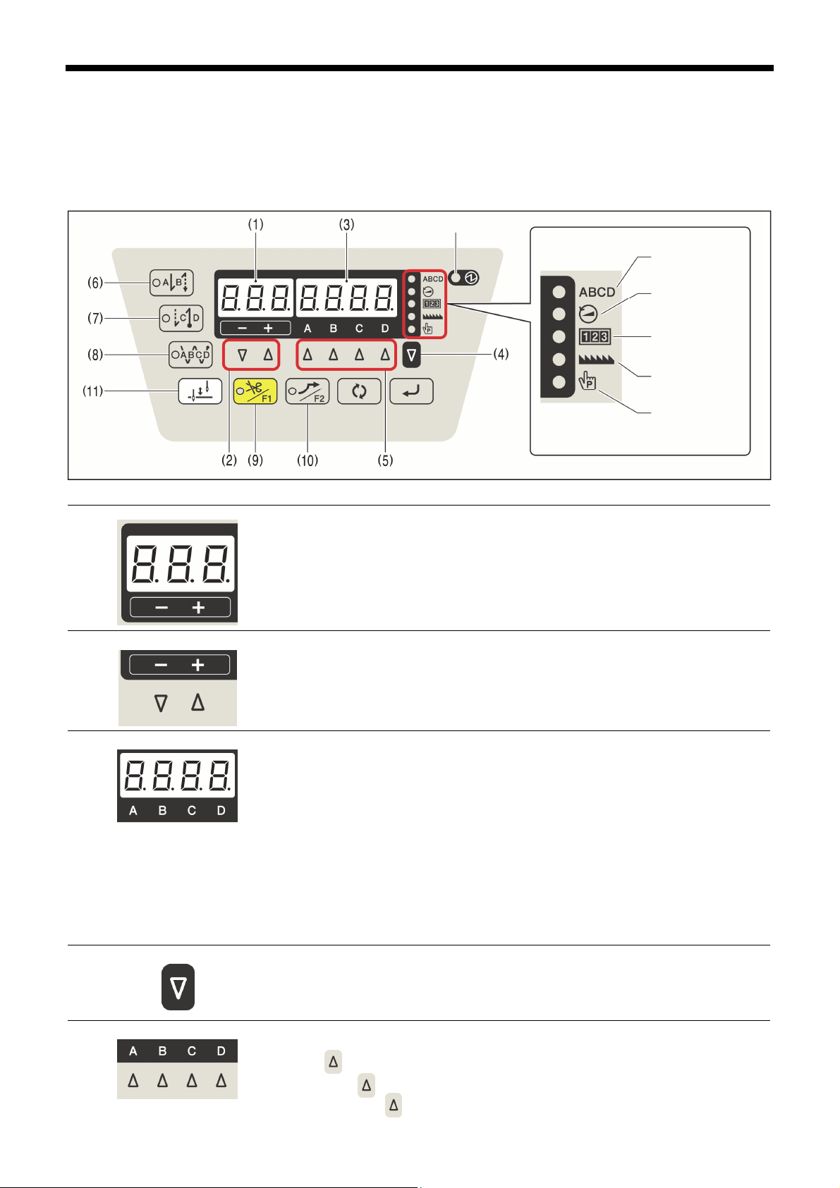
3-1. Names and functions
・ The operation panel keys cannot be operated while sewing is in progress.
Select the keys and set the number of stitches before starting sewing.
・ In the case of keys with indicators, the indicator illuminates when that function is operating, and the indicator switches off
when the key is pressed once more.
Power indicator
Stitch No. indicator
Speed indicator
Counter indicator
Locus indicator
Program indicator
1425D
The power indicator illuminates when the power switch is turned on.
(1) 3-digit display
Displays the sewing pitch.
(2) Pitch setting keys
(3) 4-digit display
(4) SEL (Select) key
Use these keys to set the sewing pitch.
・When the - key is pressed, the setting decreases in steps of 0.05 within a range of 0.05 to
5.00.
When the + key is pressed, the setting increases in steps of 0.05 within a range of 0.05 to
・
5.00.
・ When start backtack stitches are being displayed, the indicator of the start backtack key
(6) will illuminate, and the number of A stitches will appear in the A column and the
number of B stitches will appear in the B column.
・ When end backtack stitches are being displayed, the indicator of the end backtack key
(7) will illuminate, and the number of C stitches will appear in the C column and the
number of D stitches will appear in the D column.
・ When continuous backtack stitches are displayed, the indicator of the continuous
backtack key (8) will illuminate, and the number of A, B, C and D stitches will appear in
order starting from the left column of the display.
・ The five indicators on the right side of the window show which value is appearing in the
4-digit display. The 4-digit display shows the number of stitches, speed, counter, locus
and program. When the number of stitches is being displayed, the ABCD indicator (Stitch
No. indicator) will illuminate.
The value in the 4-digit display (3) can be changed each time this key is pressed.
(5) Setting keys
These keys are used to set the number of backtack stitches for A, B, C and D.
・ When the key is pressed, the setting increases from 0 up to 9.
・ If you press the key once more when “9” is displayed, the value will return to “0”.
・ If you hold down the key, the value will change continuously.
1426D
1427D
1428D
1340D
1429D
13
S-7250A
Page 23
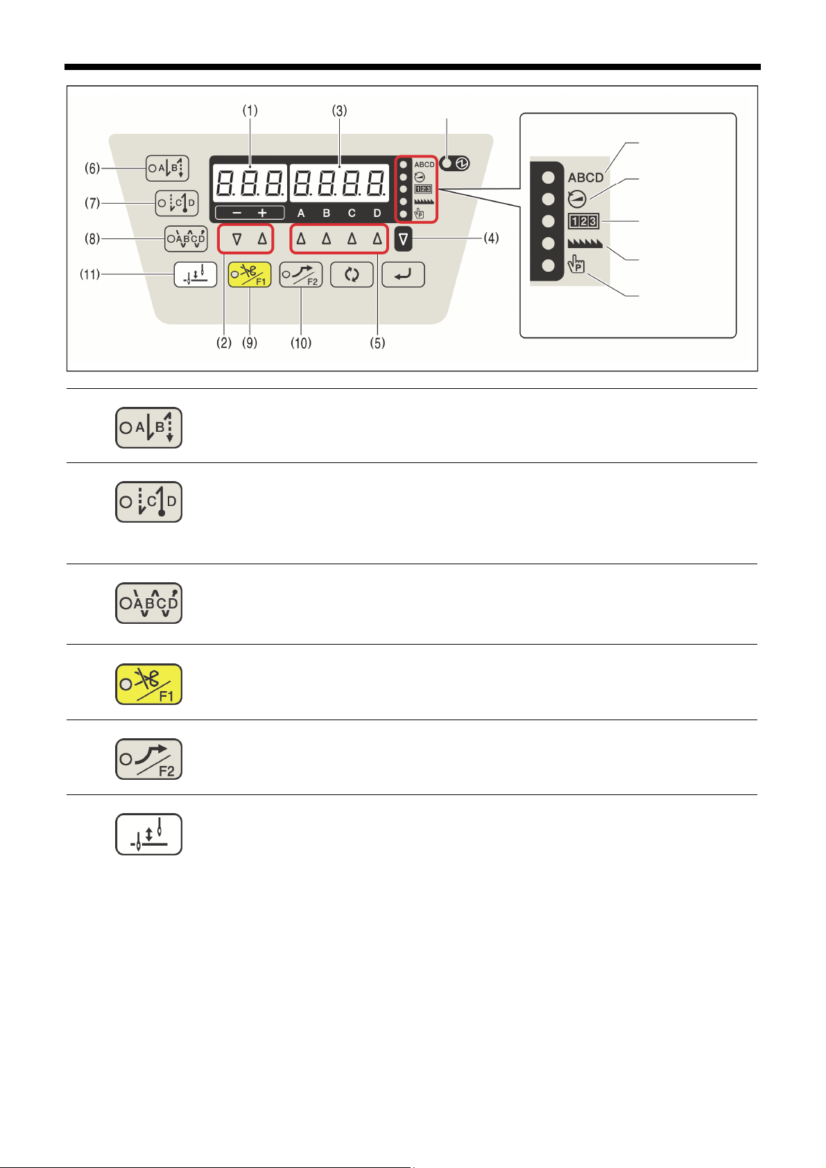
(6) Start backtack key
(7) End backtack key
(8) Continuous backtack key
(9) Thread trimming disable/F1 key
(10) Slow start/F2 key
(11) Half stitch key
3. USING THE OPERATION PANEL (BASIC OPERATIONS)
Power indicator
Stitch No. indicator
Speed indicator
Counter indicator
Locus indicator
Program indicator
1425D
When this key is pressed so that the indicator illuminates, the number of start backtack
stitches (0 - 9) in the A and B columns of the display are sewn.
1323D
When this key is pressed so that the indicator illuminates, the number of end backtack
stitches (0 to 9) in the C and D columns of the display are sewn. When the treadle is
depressed backward, the end backtack stitches are sewn and then the thread is trimmed.
If the treadle has not yet been depressed backward, the end backtack function can be set to
ON, the number of stitches can be changed and the function can be set back to OFF.
1325D
When this key is pressed so that the indicator illuminates, the number of backtack stitches
(0 to 9) in the A, B, C and D columns of the display are sewn continuously. After the sewing
machine sews a full cycle of stitches set by A, B, C and D, the thread is trimmed.
1327D
When this key is pressed so that the indicator illuminates, the sewing machine stops in the
needle up position without thread trimming being carried out even if the treadle is depressed
backward.
1330D
When this key is pressed so that the indicator illuminates, sewing is carried out at 700
sti/min for the first two stitches at the next sewing start after thread trimming.
After this, the sewing speed corresponds to the treadle depression amount.
1332D
When the sewing machine is stopped, the needle bar can be moved up and down by
pressing this key.
1329D
S-7250A
14
Page 24
3. USING THE OPERATION PANEL (BASIC OPERATIONS)
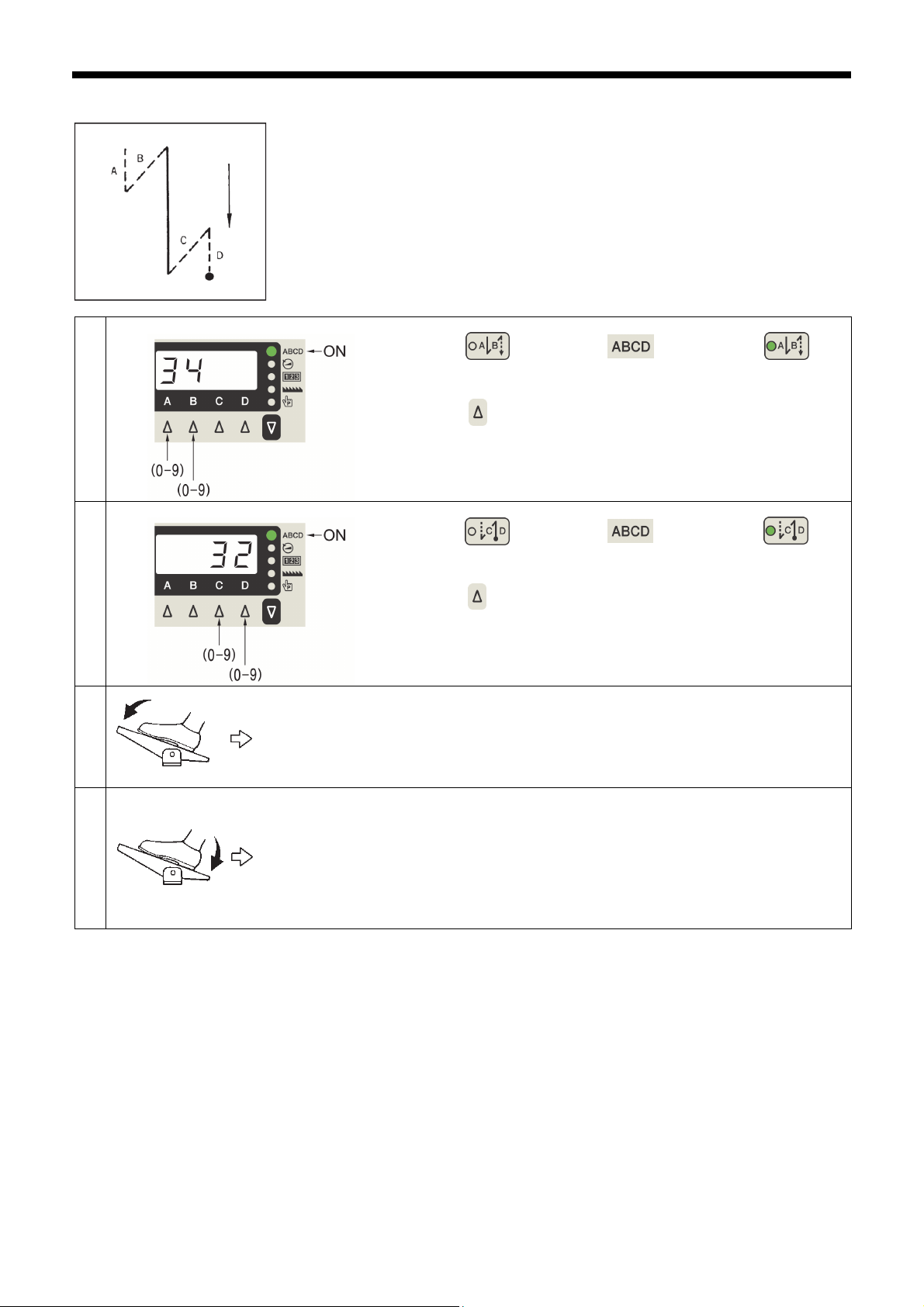
3-2. Sewing start and end backtack stitches
Setting start backtack stitches
1
Setting end backtack stitches
2
0841M
Press the key so that the indicator and the keys
illuminate.
Press the key to set the number of stitches for A and B.
For example, to select 3 stitches and 4 stitches: A-3, B-4
Press the key so that the indicator and the keys
illuminate.
1350D
3
4
Press the key to set the number of stitches for C and D.
For example, to select 3 stitches and 2 stitches: C-3, D-2
Start backtacking is carried out. After it has finished, normal sewing continues for as long as
the treadle remains depressed.
NOTE:
If the treadle is returned to the neutral position, the sewing machine will continue operating
until the set number of start backtack stitches has been sewn.
End backtacking is carried out. After it has finished, the thread is trimmed automatically and
the sewing machine stops in the needle up position.
NOTE:
・ If the treadle is depressed backward before sewing of the set number of start backtack
stitches is complete, end backtacking will not be carried out.
・ If thread trimming lock is set, the sewing machine will stop in the needle up position without
thread trimming being carried out.
1351D
2159M
2160M
15
S-7250A
Page 25
3. USING THE OPERATION PANEL (BASIC OPERATIONS)
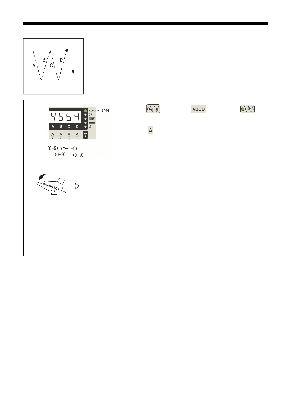
3-3. Sewing continuous backtack stitches
Sewing continuous backtack stitches
1
2
3
3655M
Press the key so that the indicator and the keys
illuminate.
Press the key to set the number of stitches for A, B, C and D.
For example, to select 4 stitches for A and 5 stitches for B: A-4, B-5
To select 5 stitches for C and 4 stitches for D: C-5, D-4
If the treadle is simply depressed continuously, the number of stitches set for A, B, C and D will
be sewn in a single cycle, the thread will be trimmed automatically and then the needle bar will
stop in the needle up position.
NOTE:
・ If the treadle is returned to the neutral position while continuous backtacking is being carried
out, the sewing machine will stop at the point where the treadle returns to the neutral
position. If the treadle is depressed again, operation will resume from the point where it was
interrupted.
・ If thread trimming lock is set, the sewing machine will stop in the needle up position without
thread trimming being carried out.
If "-" is set as the number of stitches for C, the number of stitches set by AB can be sewn D
times.
For example, if D=3: ABA
If D=6: ABABAB
1352D
2159M
S-7250A
16
Page 26

4. USING THE OPERATION PANEL (ADVANCED OPERATIONS)
4.
USING THE OPERATION PANEL (ADVANCED OPERATIONS)
The operations described in this section should only be carried out by a technician.
4-1. Sewing pitch setting method
1
2
Any
indicator
illuminates
Any
indicator
illuminates
Press the key so that the stitch no., speed, counter, locus or
program indicator illuminates.
・ The sewing pitch can be set regardless of whether the stitch no.,
speed, counter, locus or program is being displayed in the 4-digit
display.
(Refer to the Service Manual for details on programs.)
Press the - /+ keys to change the setting value.
・ When the + key is pressed, the setting value increases by
0.05.
・ When the - key is pressed, the setting value decreases by
0.05.
1353D
3
NOTE:
The setting range is from 0.05 to 5.00.
The backtack pitch can only be set when the stitch number and
sewing speed indicators are illuminated.
(Refer to "4-3-2. Backtack sewing speed setting method".)
1354D
1461D
17
S-7250A
Page 27

4. USING THE OPERATION PANEL (ADVANCED OPERATIONS)
4-2. Switching the 4-digit display
・ The 4-digit display can be changed to one of the following four statuses each time the key is pressed.
Stitch no. display or no display -> Speed display -> Counter display -> Locus display
・ When the speed display or counter display appears, you can press the key to switch to another display.
Display mode
Stitch number
display
Sewing speed
display
Counter display
Flashing Flashing
Locus display
ON
ON
ON ON
ON
Flashing
ON ON Production counter value
ON ON
4-3. Setting the sewing speed
4-3-1. Setting the maximum sewing speed
1
2
Press the key so that the indicator illuminates.
・ The maximum sewing speed setting value will appear in the 4-digit
display.
Press the C /D keys to change the setting value.
4-digit display
Maximum sewing speed setting
Backtack sewing speed setting
Lower thread counter warning
Needle replacement counter
Needle replacement counter
ON
ABCD stitch number display
value
value
Lower thread counter value
enabled
value
warning enabled
Locus setting value
1355D
・ When the D key is pressed, the setting increases by 100.
・ When the C key is pressed, the setting decreases by 100.
NOTE:
The setting range is from 220 to 4000 sti/min.
1356D
S-7250A
18
Page 28

4. USING THE OPERATION PANEL (ADVANCED OPERATIONS)
4-3-2. Backtack sewing speed setting method
1
2
Press the key so that the indicator illuminates.
・ The maximum sewing speed setting value will appear in the 4-digit
display.
Press the key.
・ The indicator will illuminate and the setting value for the
backtack sewing speed will appear in the 4-digit display.
1355D
3
NOTE:
If you press the key once more, the indicator
will switch off and the display will return to the maximum sewing
speed setting value.
Press the C /D keys to change the setting value.
・ When the D key is pressed, the setting increases by 100.
・ When the C key is pressed, the setting decreases by 100.
NOTE:
The setting range is from 220 to 3000 sti/min.
1357D
1358D
19
S-7250A
Page 29

4. USING THE OPERATION PANEL (ADVANCED OPERATIONS)
4-4. Setting the counters
The lower thread counter, production counter and needle replacement counter are available.
The three counters can be operated at the same time.
4-4-1. Lower thread counter
The lower thread counter can be used to let you know approximately how much lower thread is remaining.
* This function is only displayed when "A09: Lower thread counter operation" is set to "ON".
Refer to "4-6-7. Lower thread counter operation".
<Setting the lower thread counter initial value>
1
2
Press the key so that the indicator illuminates.
・ The lower thread counter value will appear in the 4-digit display.
Press the A key for 2 seconds or more, and then press the C
or D key to set the initial value.
・ When the D key is pressed, the setting value increases by 0.1.
・ When the C key is pressed, the setting value decreases by
0.1.
NOTE:
・ The setting range is from 0.1 to 99.9.
1359D
1360D
<Lower thread counter operation>
・ The lower thread counter can be used to let you know approximately how much lower thread is remaining.
* The lower thread counter should be used as a guide only.
・ The value displayed by the lower thread counter display is reduced by 0.1 from the initial setting value each time the number
of stitches x sewing pitch reaches 0.1 m, and a warning is given when the counter goes below 0.
When the warning occurs, the counter indicator blinks and the buzzer sounds
for 5 seconds.
1361D
・ Sewing will be possible even after the treadle is returned to the neutral position and the sewing machine stops. However,
after the treadle has been depressed backward and thread trimming has been carried out, sewing using the treadle will no
longer be possible.
If the treadle is depressed at this time, “ Ent” will appear in the display. When the treadle is returned to the neutral position,
the display will return to the current counter display.
・ If the key is pressed during a warning, the indicator will change to illuminated and sewing can then be
carried out using the treadle.
If the A key is pressed again for 2 seconds or more, the counter display will return to the initial value and counting from
the initial value will be possible.
S-7250A
20
Page 30

4. USING THE OPERATION PANEL (ADVANCED OPERATIONS)
4-4-2. Production counter
The production counter can be used to let you know how many items have been sewn.
1
2
After the thread trimming operation is complete, the
counter will be incremented.
3
4
Press the key so that the indicator illuminates.
・ The lower thread counter value will appear in the 4-digit
display.
When the key is pressed once, the production counter
will be displayed.
・ The production counter value will appear in the 4-digit
display.
NOTE:
The counter is incremented when the treadle is depressed
backward even if thread trimming is set to disabled.
When the production counter is displayed, you can press the C
or D key to adjust the counter value (0 to 9999).
1359D
1362D
・ When the D key is pressed, the counter value increases
by 1.
・ When the C key is pressed, the counter value decreases
by 1.
・ If you press the A key for 2 seconds or more, the counter
value can be reset to "0".
1363D
21
S-7250A
Page 31

4-4-3. Needle replacement counter
<Setting the needle replacement counter initial value>
1
2
3
Press the key so that the indicator illuminates.
・ The lower thread counter value will appear in the 4-digit display.
When the key is pressed two or more times, the needle
replacement counter display will appear.
・ The needle replacement counter value will appear in the 4-digit
Press the A key for 2 seconds or more, and then press the C
or D key to set the initial value.
4. USING THE OPERATION PANEL (ADVANCED OPERATIONS)
1359D
display.
1364D
・ When the D key is pressed, the setting value increases by 1.
・ When the C key is pressed, the setting value decreases by 1.
NOTE:
・ The setting range is from 0 to 9999.
・ If an initial value of “0” is set, the needle replacement counter will
not operate.
1365D
<Needle replacement counter operation>
・ The needle replacement counter is reduced by 1 from the initial setting value each time the sewing machine sews 100
stitches, and a warning is given when the counter goes below “0”.
When the warning occurs, the indicator and the indicator flash,
and the buzzer sounds for 5 seconds.
1366D
・ Sewing will be possible even after the treadle is returned to the neutral position and the sewing machine stops. However,
after the treadle has been depressed backward and thread trimming has been carried out, sewing using the treadle will no
longer be possible.
If the treadle is depressed at this time, “Ent” will appear in the display. When the treadle is returned to the neutral position,
the display will return to the current counter display.
・ If the key is pressed during a warning, the indicator and the indicator will change to illuminated and
sewing can then be carried out using the treadle.
If the A key is pressed again for 2 seconds or more, the counter display will return to the initial value and counting from
the initial value will be possible.
S-7250A
22
Page 32

4. USING THE OPERATION PANEL (ADVANCED OPERATIONS)
4-5. Sewing locus setting method
Sewing locus setting method
1
2
Press the key so that the indicator illuminates.
・ The sewing locus setting value will appear in the 4-digit display.
Press the C /D keys to change the setting value.
・ When the D key is pressed, the setting value increases by 1.
・ When the C key is pressed, the setting value decreases by 1.
NOTE:
The setting range is from 0 to 3.
0: The feed dog moves along the standard locus.
1: The feed dog moves along special locus 1.
2: The feed dog moves along special locus 2.
3: The feed dog moves along special locus 3.
1367D
1368D
1478D
23
S-7250A
Page 33

4. USING THE OPERATION PANEL (ADVANCED OPERATIONS)
4-6. Setting basic functions
If you hold down the key and press the key while the stitch no., speed, counter, locus or program is displayed,
the following items can be set.
Setting item 3-digit
display
Needle up/down
Thread trimming disable
『A01』 『UPdn』
『A02』 『trdi』
4-digit
display
Initial value Reference item
Needle down stop Refer to ”4-6-1”.
None
(Thread trimming
operation enabled)
Press the key to
make the setting.
Thread wiping
Correction sewing
AUTO
Auto thread trimming
Slow start
Illumination LED brightness
Lower thread counter operation
Prev. thread away
Prev. thread away pitch at 1st stitch
Prev. thread away pitch at 2nd stitch
Short trailing thread
Short trailing thread sewing speed at 1st
stitch
Short trailing thread sewing speed at
2nd stitch
Short trailing thread pitch at 1st stitch
Short trailing thread pitch at 2nd stitch
Short trailing thread pitch at 3rd stitch
Short trailing thread direction
Standard switch correction sewing
function
Function other than standard switch
correction sewing
2nd pitch ratio 『A33』 『 2Pt』
Correction 2nd pitch ratio 『A34』 『A2Pt』
Option switch correction sewing function
Function other than option switch
correction sewing
『A03』 『 WiP』
『A04』 『Corr』
『A05』 『AUto』
『A06』 『AtiM』
『A07』 『SLoW』
『A08』 『 LEd』
『A09』 『UtCt』
『A11』 『 PtA』
『A12』 『PtP1』
『A13』 『PtP2』
『A21』 『ttSH』
『A22』 『ttr1』
『A23』 『ttr2』
『A24』 『ttP1』
『A25』 『ttP2』
『A26』 『ttP3』
『A27』 『ttCS』
『A31』 『HSCF』
『A32』 『HSoF』
『A35』 『oSCF』
『A36』 『oSoF』
Specifications with
thread wiper: Enabled
Specifications without
thread wiper: Disabled
None
None Refer to the Service Manual.
None Refer to the Service Manual.
None
Level 5
None
None
3.30
2.20
P specifications:
Enabled
S specifications:
Disabled
1400
400
0.70
0.70
1.20
Fw: Forward direction
1: Single correction
sewing
1: Reverse
50
50
1: Single correction
sewing
1: Reverse
Refer to ”4-6-3”.
Press the key to
make the setting.
S-7250A
24
Page 34

4. USING THE OPERATION PANEL (ADVANCED OPERATIONS)
(
p)
(
p)
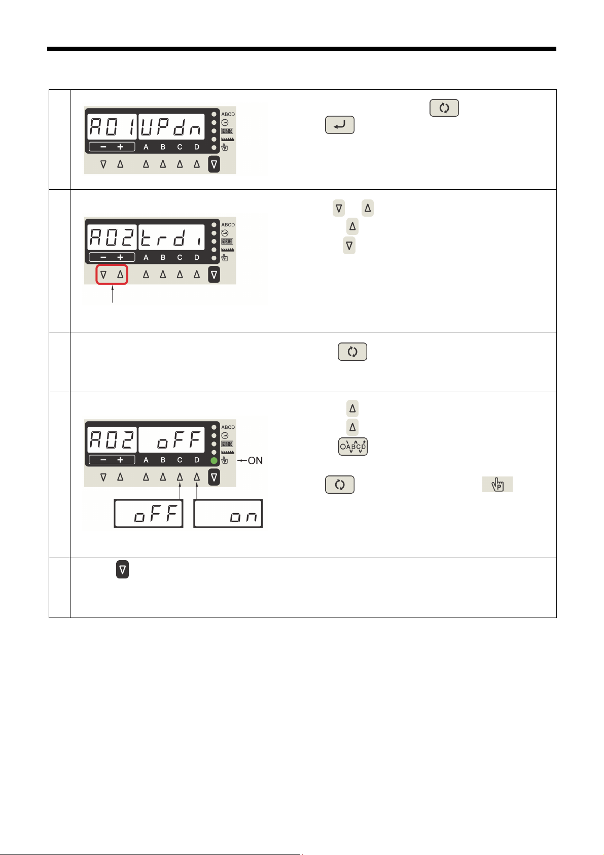
4-6-1. Changing the needle stop position
This sets whether the needle bar stops in the needle up stop position or the needle down stop position when the treadle is
returned to the neutral position and sewing stops.
1
Displaying the needle up stop and needle down
stop setting values
2
Setting the needle up stop and needle down
stop positions
3
In sewing standby mode, press the key while holding down
the key to switch to function setting mode.
・ "A01 UPdn" will be displayed.
1369D
・ When the key is pressed, the setting value is displayed.
・ When the D key is pressed, the “UP” display will appear.
・ When the C key is pressed, the “dn” display will appear.
・ When the key is pressed, the initial value will be reset.
Press the key.
4
Needle down sto
Needle up sto
NOTE:
If the key is pressed once more, the indicator
will switch off and the display will return to the setting item.
1370D
Setting mode will be exited and normal operation will be possible.
25
S-7250A
Page 35
)
4. USING THE OPERATION PANEL (ADVANCED OPERATIONS)
4-6-2. Thread trimming disable
If thread trimming is set to be disabled, thread trimming will not be carried out even when the pedal is depressed backward.
1
Selecting “A02 Trdi” (thread trimming disable)
2
In sewing standby mode, press the key while holding
down the key to switch to function setting mode.
・ "A01 UPdn" will be displayed.
Press the - / + keys to select "A02 Trdi".
1369D
Press either.
Displaying the thread trimming disabled setting
value
3
Setting thread trimming to disabled or enabled
4
Press the key.
5
(Thread trimming
operation enabled)
(Thread trimming
disable
・ When the
・ When the - key is pressed, the previous setting is displayed.
・ When the key is pressed, the setting value is displayed.
・ When the D key is pressed, the “on” display will appear.
・ When the C key is pressed, the “oFF” display will appear.
・ When the key is pressed, the initial value will be reset.
NOTE:
If the key is pressed once more, the indicator
will switch off and the display will return to the setting item.
Setting mode will be exited and normal operation will be possible.
+ key is pressed, the next setting is displayed.
1371D
1372D
S-7250A
26
Page 36

4. USING THE OPERATION PANEL (ADVANCED OPERATIONS)
(
)
4-6-3. Thread wiping
You can set whether thread wiper operation is enabled or disabled.
1
Selecting “A03 Wip” (thread wiping)
2
Press either.
Displaying the thread wiping setting value
3
In sewing standby mode, press the key while holding down
the key to switch to function setting mode.
・ "A01 UPdn" will be displayed.
Press the - / + keys to select "A03 Wip".
・ When the + key is pressed, the next setting is displayed.
・ When the - key is pressed, the previous setting is displayed.
・ When the key is pressed, the setting value is displayed.
1369D
1373D
Setting thread wiping
4
Press the key.
5
Thread wiping disabled) (Thread wiping enabled
・ When the D key is pressed, the “on” display will appear.
・ When the C key is pressed, the “oFF” display will appear.
・ When the key is pressed, the initial value will be reset.
NOTE:
If the key is pressed once more, the indicator
will switch off and the display will return to the setting item.
Setting mode will be exited and normal operation will be possible.
1374D
27
S-7250A
Page 37

4. USING THE OPERATION PANEL (ADVANCED OPERATIONS)
4-6-4. Correction sewing
When correction sewing is enabled, if the hand switch is pressed while sewing is stopped before thread trimming, one stitch
will be sewn and sewing will then stop.
* The function can be changed. (Refer to "4-11. Hand switch".)
1
Selecting “A04 Corr” (correction sewing)
2
Press either.
Displaying the correction sewing setting value
3
In sewing standby mode, press the key while holding down
the key to switch to function setting mode.
・ "A01 UPdn" will be displayed.
1369D
Press the - or + key to select "A04 Corr".
・ When the + key is pressed, the next setting is displayed.
・ When the - key is pressed, the previous setting is displayed.
1375D
・ When the key is pressed, the setting value is displayed.
Setting correction sewing
4
(Correction sewing disabled)
Press the key.
5
(Correction sewing enabled)
・ When the D key is pressed, the “on” display will appear.
・ When the C key is pressed, the “oFF” display will appear.
・ When the key is pressed, the initial value will be reset.
NOTE:
If the key is pressed once more, the indicator
will switch off and the display will return to the setting item.
Setting mode will be exited and normal operation will be possible.
1376D
S-7250A
28
Page 38

4. USING THE OPERATION PANEL (ADVANCED OPERATIONS)
(
)
(
)
4-6-5. Slow start
If slow start is enabled, occurrences of the thread pulling out can be reduced.
1
Selecting “A07 SLow” (slow start)
2
Press either.
Displaying the slow start setting value
3
In sewing standby mode, press the key while holding down
the key to switch to function setting mode.
・ "A01 UPdn" will be displayed.
Press the - or + key to select "A07 SLow".
・ When the + key is pressed, the next setting is displayed.
・ When the - key is pressed, the previous setting is displayed.
・ When the key is pressed, the setting value is displayed.
1369D
1377D
Setting slow start
4
Press the key.
5
Slow start disabled
Slow start enabled
・ When the D key is pressed, the setting value increases in the
order "oFF", "1", "2", "3".
・ When the C key is pressed, the setting value decreases in the
order "3", "2", "1", "oFF".
・ When the key is pressed, the initial value will be reset.
・ Sewing speed for first 4 stitches when slow start is enabled
1: 400, 400, 400, 4000*
2: 400, 400, 4000*, 4000*
3: 700, 700, 4000*, 4000*
4: Set using memory switch Nos. 403 to 406.
* If the maximum sewing speed is set to 4,000 sti/min
NOTE:
If the key is pressed once more, the indicator
will switch off and the display will return to the setting item.
Setting mode will be exited and normal operation will be possible.
1378D
29
S-7250A
Page 39

4-6-6. Setting the illumination LED light
You can set the brightness of the illumination LED light.
1
Selecting "A08 LEd" (illumination LED light)
2
Press either.
Displaying the illumination LED light setting
value
3
Setting the illumination LED light
4
4. USING THE OPERATION PANEL (ADVANCED OPERATIONS)
In sewing standby mode, press the key while holding down
the key to switch to function setting mode.
・ "A01 UPdn" will be displayed.
1369D
Press the - or + key to select "A08 LEd".
・ When the + key is pressed, the next setting is displayed.
・ When the - key is pressed, the previous setting is displayed.
1379D
・ When the key is pressed, the setting value is displayed.
・ When the D key is pressed, the setting value increases from
"1" through to "9".
・ When the C key is pressed, the setting value decreases from
"9" through to "1".
・ When the key is pressed, the initial value will be reset.
Press the key.
5
(Dark) (Bright)
NOTE:
If the key is pressed once more, the indicator
will switch off and the display will return to the setting item.
Setting mode will be exited and normal operation will be possible.
1380D
S-7250A
30
Page 40

4. USING THE OPERATION PANEL (ADVANCED OPERATIONS)
4-6-7. Setting lower thread counter operation
The lower thread counter function can be set to enabled or disabled.
1
Selecting "A09 UtCt" (lower thread counter
operation)
2
Press either.
Displaying the lower thread counter operation
setting value
3
In sewing standby mode, press the key while holding down
the key to switch to function setting mode.
・ "A01 UPdn" will be displayed.
Press the - or + key to select "A09 UtCt".
・ When the + key is pressed, the next setting is displayed.
・ When the - key is pressed, the previous setting is displayed.
・ When the key is pressed, the setting value is displayed.
1369D
1462D
Setting lower thread counter operation
4
Press the key.
5
(Lower thread
counter disabled)
(Lower thread
counter enabled)
・ When the D key is pressed, the “on” display will appear.
・ When the C key is pressed, the “oFF” display will appear.
・ When the key is pressed, the initial value will be reset.
NOTE:
If the key is pressed once more, the indicator
will switch off and the display will return to the setting item.
Setting mode will be exited and normal operation will be possible.
1463D
31
S-7250A
Page 41

4. USING THE OPERATION PANEL (ADVANCED OPERATIONS)
4-6-8. Prev. thread away
When "Prev. thread away" is enabled, the pitch at the sewing start can be increased in order to reduce cases of the thread
pulling out.
1
Selecting “A11 PtA” (prev. thread away)
2
Press either.
Displaying the "Prev. thread away" setting
value
3
Setting "Prev. thread away"
4
In sewing standby mode, press the key while holding down
the key to switch to function setting mode.
・ "A01 UPdn" will be displayed.
1369D
Press the - or + key to select "A11 PtA".
・ When the + key is pressed, the next setting is displayed.
・ When the - key is pressed, the previous setting is displayed.
1381D
・ When the key is pressed, the setting value is displayed.
・ When the D key is pressed, the “on” display will appear.
Press the key.
5
("Prev. thread
away" function
is disabled)
("Prev. thread
away" function
is enabled)
・ When the C key is pressed, the “oFF” display will appear.
・ When the key is pressed, the initial value will be reset.
NOTE:
If the key is pressed once more, the indicator
will switch off and the display will return to the setting item.
1382D
Setting mode will be exited and normal operation will be possible.
S-7250A
32
Page 42

4. USING THE OPERATION PANEL (ADVANCED OPERATIONS)
4-6-9. Short trailing thread
When short trailing thread is enabled, the trailing length of the thread can be made shorter.
1
Selecting "A21 ttSH" (short trailing thread)
2
Press either.
Displaying the short trailing thread setting value
3
In sewing standby mode, press the key while holding down
the key to switch to function setting mode.
・ "A01 UPdn" will be displayed.
Press the - or + key to select "A21 ttSH".
・ When the + key is pressed, the next setting is displayed.
・ When the - key is pressed, the previous setting is displayed.
・ When the key is pressed, the setting value is displayed.
1369D
1383D
Setting short trailing thread
4
Press the key.
5
(Short trailing
thread function
disabled)
(Short trailing
thread function
enabled)
・ When the D key is pressed, the “on” display will appear.
・ When the C key is pressed, the “oFF” display will appear.
・ When the key is pressed, the initial value will be reset.
NOTE:
If the key is pressed once more, the indicator
will switch off and the display will return to the setting item.
Setting mode will be exited and normal operation will be possible.
1384D
33
S-7250A
Page 43

4. USING THE OPERATION PANEL (ADVANCED OPERATIONS)
4-6-10. Correction sewing function (1)
When the correction sewing function (A04) is enabled, the hand switch correction sewing function can be set.
For details on the functions which can be set, refer to "4-11. Hand switch" for the settings when the hand switch is set as a
correction sewing switch.
1
Selecting "A31 HSCF" (correction sewing
function)
2
In sewing standby mode, press the key while holding down
the key to switch to function setting mode.
・ "A01 UPdn" will be displayed.
1369D
Press the - or + key to select "A31 HSCF".
・ When the + key is pressed, the next setting is displayed.
・ When the - key is pressed, the previous setting is displayed.
Press either.
Displaying the correction sewing function
setting value
3
Setting the correction sewing function
4
Press the key.
5
(Correction
sewing function
disabled)
(Correction
sewing function
enabled)
1385D
・ When the key is pressed, the setting value is displayed.
・ When the D key is pressed, the setting value increases from
"oFF" to "1" through to "9".
・ When the C key is pressed, the setting value decreases from
"9" through to "1" to "oFF".
・ When the key is pressed, the initial value will be reset.
NOTE:
If the key is pressed once more, the indicator
will switch off and the display will return to the setting item.
Setting mode will be exited and normal operation will be possible.
1386D
S-7250A
34
Page 44

4. USING THE OPERATION PANEL (ADVANCED OPERATIONS)
4-6-11. Correction sewing function (2)
When the correction sewing function (A04) is disabled, the hand switch functions other than correction sewing can be set.
For details on the functions which can be set, refer to "4-11. Hand switch" for the settings when the hand switch is set to other
than a correction sewing switch.
1
Selecting "A32 HSoF" (correction sewing
function)
2
In sewing standby mode, press the key while holding down
the key to switch to function setting mode.
・ "A01 UPdn" will be displayed.
1369D
Press the - or + keys to select "A32 HSoF".
・ When the + key is pressed, the next setting is displayed.
・ When the - key is pressed, the previous setting is displayed.
Press either.
Displaying the setting value for a function other
than correction sewing
3
・ When the key is pressed, the setting value is displayed.
Setting a function other than correction sewing
4
・ When the D key is pressed, the setting value increases from
"oFF" to "1" through to "16".
・ When the C key is pressed, the setting value decreases from
"16" through to "1" to "oFF".
・ When the key is pressed, the initial value will be reset.
NOTE:
If the key is pressed once more, the indicator
(Function other
than correction
sewing is disabled)
(Function other
than correction
sewing is enabled)
will switch off and the display will return to the setting item.
Press the key.
5
Setting mode will be exited and normal operation will be possible.
1387D
1388D
35
S-7250A
Page 45

4-7. Memory switch setting method
1
Selecting a memory switch number
2
Previous
item
Next item
Selecting a memory switch number which is
different from the initial value
3
In sewing standby mode, press the key while holding down the
・ "001" or the memory switch number which was set previously will
Press the - / + keys to select the number for the memory
switch to be set.
・ When the + key is pressed, the next setting is displayed.
・ When the - key is pressed, the previous setting is displayed.
While pressing the key, press the - / + keys to select
the number for the memory switch which is different from the initial
value.
4. USING THE OPERATION PANEL (ADVANCED OPERATIONS)
key to switch to memory switch setting mode.
be displayed.
1389D
1390D
Previous
item
Next item
Changing the memory switch setting value
4
Decreases the value
Confirming the memory switch setting value
Increases the value
5
・ When the + key is pressed while holding down the key,
the next setting item is displayed.
・ When the - key is pressed while holding down the key,
the previous setting item is displayed.
・ When the D key is pressed, the setting value increases or it
turns ON.
・ When the C key is pressed, the setting value decreases or it
turns OFF.
・ When the key is pressed the initial value will be set.
・ When the key is pressed, the setting value is confirmed.
1390D
1392D
Press the key.
6
Setting mode will be exited and normal operation will be possible.
S-7250A
36
Page 46

4. USING THE OPERATION PANEL (ADVANCED OPERATIONS)
4-8. List of memory switch settings
Presser foot lifter and treadle settings (001 to 099)
No.
001 ON/OFF
002 ON/OFF OFF -
003 ON/OFF ON -
004 ON/OFF ON -
010 ON/OFF OFF -
011 0 - 1 0 1
012
013 ON/OFF ON -
014 ON/OFF ON -
015 ON/OFF ON -
Setting
range
0 - 500
(ms)
Initial value
ON : Other
than
Europe and
America /
OFF :
Europe and
America
80
(ms)
Setting
units
-
10
(ms)
Presser foot condition when treadle is returned to neutral position after
thread trimming
ON: Presser foot is raised
OFF: Presser foot is not raised
(*) The presser foot lifts when No.851 is set to "OFF".
Presser foot condition when operation stops at the neutral treadle position
ON: Presser foot is raised
OFF: Presser foot is not raised
Presser foot raising after treadle is returned to neutral position to stop
sewing and is then depressed backward to the 1st step
ON : Enabled
OFF: Disabled
Operation when treadle is depressed backward
ON: Thread trimming and end backtack sewing operations are enabled
(However, if thread trimming operation is locked, needle up
operations will be carried out without thread trimming.)
OFF: Thread trimming and end backtack sewing operations are disabled
(presser foot lifts when the treadle is depressed backward)
Alternating operation of standing operation pedal and treadle
(*) For simultaneous operation which includes operation of the presser
foot lifter pedal, operation of the standing operation pedal takes priority.
ON: Treadle operation is still enabled after standing operation pedal has
been used (alternating operation is possible)
OFF: Treadle operation is disabled after standing operation pedal has
been used
Operation when standing up variable speed pedal is ON
0: Sewing speed corresponds to treadle depression amount
1: Operates at the sewing speed for the main section (constant speed)
Delay time from standing pedal turning on until motor starts operating
Stop function using the work clamp pedal during standing operation when
the AUTO function is on
ON: Sewing is interrupted when presser foot lifter pedal turns on (pause
operation)
(*) This function is disabled during start backtacking.
OFF: No operation
Pause function using the high-speed pedal during standing operation
when the AUTO function is on
ON: When the high-speed pedal turns on, sewing is momentarily stopped,
and it is resumed when the pedal turns off.
(*) This function is disabled when No. 010 is set to "ON".
(*) This function is disabled during start backtacking.
OFF: No operation
Presser foot lifting operation from thread trimming pedal after thread is
trimmed during standing operation
ON: Presser foot can be raised and lowered
(*) If No.051 is set to "ON", thread trimming pedal operation is disabled
after the presser foot lifter pedal has been operated during standing
operation.
OFF: No operation (only possible using presser foot lifter pedal)
Setting details
37
S-7250A
Page 47

Sewing machine motor settings (100 to 199)
No.
100 OFF, 1 - 3 OFF 1
101 1 - 5 1 1
102
103
Setting
range
-20 - 10
(Degrees) 0 (Degrees)1 (Degrees)
-10 - 10
(Degrees) 0 (Degrees)1 (Degrees)
Initial
value
Setting
units
4. USING THE OPERATION PANEL (ADVANCED OPERATIONS)
Pedal response switching settings immediately after sewing has started
OFF: No switching
1: Slow start only when sewing starts after thread trimming
2: Slow start only when sewing starts after sewing has been paused
3: Slow start always when sewing starts
Pedal response immediately after sewing has started
(The larger the value, the slower the speed when sewing starts.)
* When No. 100 is set to "OFF", nothing is displayed. (The setting is
disabled.)
Needle up stop position correction value
Needle up stop position = Needle up stop position initial setting value +
Upper shaft reference position correction value + Needle up stop position
correction value
Needle down stop position correction value
Needle down stop position = Needle down stop position initial setting
value + Upper shaft reference position correction value + Needle down
stop position correction value
Feed motor settings (200 to 299)
No.
200
201
202
203
204
205
206
Setting
range
50 - 150
(%)
50 - 150
(%)
50 - 150
(%)
50 - 150
(%)
50 - 150
(%)
50 - 150
(%)
50 - 150
(%)
Initial
value
100
(%)
100
(%)
100
(%)
100
(%)
100
(%)
-3: 100
-5: 97
(%)
92
(%)
Setting
units
1
(%)
1
(%)
1
(%)
1
(%)
1
(%)
1
(%)
1
(%)
Forward direction pitch correction ratio
Reverse direction pitch length correction ratio
Start backtacking B pitch correction ratio
End backtacking C pitch correction ratio
Special locus 1 pitch correction ratio
Special locus 2 pitch correction ratio
Special locus 3 pitch correction ratio
Panel operation settings (300 to 399)
No.
300 1 - 3 1 1
312 0 - 2 0 1
Setting
range
Initial
value
Setting
units
Operation after lower thread counter warning
1: Sewing can continue until thread trimming is carried out
2: After sewing stops, it cannot continue until the [ENTER] key is pressed
and the warning is canceled.
3: If the counter goes below "0", sewing stops, and the warning operation
for a setting of "2" occurs.
Feed pitch display mode
0: mm display
1: stitch per inch display
2: stitch per 30 mm display
Setting details
Setting details
Setting details
S-7250A
38
Page 48

4. USING THE OPERATION PANEL (ADVANCED OPERATIONS)
Sewing program settings (400 to 499)
No.
400 ON/OFF OFF -
401 ON/OFF ON -
Setting
range
Initial
value
Setting
units
Stopping while start backtacking is in progress, and speed during start
backtacking
ON: When the treadle is returned to the neutral position, start backtacking
can be stopped before it is finished, and the speed during start
backtacking becomes the speed corresponding to the treadle
depression amount (low speed - start backtacking speed)
OFF: When the treadle is returned to the neutral position, start backtacking
ends, sewing stops and the sewing speed becomes the start
backtacking speed (constant)
Feed direction when sewing machine motor is stopped immediately after
start backtacking is complete
OFF: Sewing machine motor stops after start backtacking
is complete
(*) If No. 400 is set to "OFF", operation occurs when the
treadle is depressed slightly.
ON: After start backtack sewing, the feed moves forward,
then the sewing machine motor stops.
403
404
405
406
408 2 - 6 2 1
300 - 4000
(sti/min)
300 - 4000
(sti/min)
300 - 4000
(sti/min)
300 - 4000
(sti/min)
4000
(sti/min)
4000
(sti/min)
4000
(sti/min)
4000
(sti/min)
100
(sti/min)
100
(sti/min)
100
(sti/min)
100
(sti/min)
1st stitch sewing speed for slow start
2nd stitch sewing speed for slow start
3rd stitch sewing speed for slow start
4th stitch sewing speed for slow start
Repeat pattern when start backtacking sewing pattern (AB) is selected
2: A - B
3: B - A - B
4: A - B - A - B *Same as AB (x2)
5: B - A - B - A - B
6: A - B - A - B - A - B *Same as AB (x3)
Setting details
Operation mode for manual production counter increment function using
hand switch
409 0 - 1 0 1
0: Counter can be incremented at any time
1: Counter can only be incremented after sewing stops and thread has
been trimmed
39
S-7250A
Page 49

Standard device settings (500 to 599)
No.
500 OFF, 1 - 3 1 1
501 OFF, 1 - 2 OFF 1
502
503
504
505
506
507
508
509
Setting
range
90 - 270
(Degrees)
270 - 430
(Degrees)
-50 - 50
(Degrees) 0 (Degrees)
-50 - 50
(Degrees) 0 (Degrees)
-50 - 50
(Degrees) 0 (Degrees)
-50 - 50
(Degrees) 0 (Degrees)
-50 - 50
(Degrees) 0 (Degrees)
-50 - 50
(Degrees) 0 (Degrees)
Initial
value
180
(Degrees)
320
(Degrees)
Setting
units
Presser foot lifter SW function
OFF: Disabled
1: Presser foot lifter switch
2: Puller switch (switching)
3: Puller switch
* Puller operation is enabled when No. 960 is set to "1", and it does not
operate when set to other than "OFF".
Thread holder operation setting
OFF: Thread holder does not operate
1: On according to the timing set by No. 502, and off according to the timing
2: On together with starting of machine motor, and off according to the timing
Thread presser ON timing (upper shaft angle)
1
1
1 Feed timing for 1st stitch at sewing start *1
1 Feed timing for 2nd stitch at sewing start *1
1 Feed timing for 3rd stitch at sewing start *1
1 Feed timing for 1st stitch at sewing end *2
1 Feed timing for 2nd stitch at sewing end *2
1 Feed timing for 3rd stitch at sewing end *2
(*) When No. 501 is set to "OFF" or "2", nothing is displayed. (The setting is
Thread presser OFF timing (upper shaft angle)
(*) When No. 501 is set to "OFF", nothing is displayed. (The setting is
4. USING THE OPERATION PANEL (ADVANCED OPERATIONS)
set by No. 503
set by No. 503
disabled.)
disabled.)
Setting details
S-7250A
40
Page 50

4. USING THE OPERATION PANEL (ADVANCED OPERATIONS)
4-9. Reading and writing data using USB media
Programs and memory switch data can be copied between sewing machines by means of USB media.
CAUTION
Turn off the power before connecting the USB memory.
Do not connect anything to the USB port other than the USB memory. If this is not observed, problems with
operation may result. Attach the cap after use.
USB cap
USB port
1
1. Press the - / + keys to select the item to read/write.
2
2. Press the key to run the selected read/write item.
1. First connect the USB media to the sewing machine.
2. While pressing the key, turn on the power switch.
・ "B01 MAIn" will be displayed.
1464D
1465D
3. When the key is pressed, normal sewing machine operation will be possible.
The read/write items that can be selected are as follows.
3-digit
display
『B81』 『PRGR』 Read all programs
『B82』 『PRGW』
『B83』 『MSWR』 Read all memory switches
『B84』 『MSWW』 Write all memory switches
『B85』 『ADTR』 Read all data
『B86』 『ADTW』 Write all data
『B87』
『B88』 『ERRW』 Write error log
Create folders for USB media
Memory switches ISMMSW.SEW Same as above
Cycle programs ISMCYC.SEW Same as above
Program functions in common ISMCOM.SEW Same as above
Design stitches ISMDST.SEW Same as above
Hand switch ISMHSW.SEW Same as above
Production data P*******.LDT Same as above
4-digit
display
Write all programs
『PDIW』
Data type File name Folder name
Program ISMUPG.SEW
Error log
Write production
information
Setting item Read/write direction
USB media → (Panel) →Sewing machine
USB media ← (Panel) ←Sewing machine
USB media → (Panel) →Sewing machine
USB media ← (Panel) ←Sewing machine
USB media → (Panel) →Sewing machine
USB media ← (Panel) ←Sewing machine
USB media ← (Panel) ←Sewing machine
USB media ← (Panel) ←Sewing machine
¥BROTHER¥ISM¥ISMDL**
(** is the value for MSW-750)
(Refer to the Service Manual
for details on MSW-750.)
E*******.LDT
M*******.LDT
¥BROTHER¥ISM¥ISMLDT¥
41
S-7250A
Page 51

4. USING THE OPERATION PANEL (ADVANCED OPERATIONS)
4-10. Resetting all settings to their defaults
If the sewing machine stops operating normally, the cause may be that an incorrect setting may have been made for the
memory data by means of memory switches, for instance. In such cases, it may be possible to restore normal operation by
following the steps given below to initialize the memory setting data.
1. While pressing the key, turn on the power switch.
The mode will switch to initialization mode and "C01 ALLC" will appear in the display.
2. Press the - / + keys to select the item to be initialized.
3-digit display 4-digit display Initialization item
『C01』 『ALLC』
『C02』 『MSWC』
『C03』 『PGMC』
『C04』 『PDIC』
3. Press the key for 2 seconds or more.
When initialization is complete, the 4-digit display will change to show "End", and then after one second it will switch back to
the previous display.
4. Press the key.
Initialization mode will be exited and normal sewing machine operation will then be possible.
* For details on initialization items other than “C01 ALL”, refer to the Service Manual.
Clear all
Memory switch initialization
Program initialization
Production data initialization
S-7250A
42
Page 52

4. USING THE OPERATION PANEL (ADVANCED OPERATIONS)
4-11. Hand switch
The following functions can be set for the hand switch.
When the correction sewing setting is "ON", the hand switch operates as a correction sewing switch, and when the correction
sewing setting is "OFF", the hand switch operates as a switch for functions other than correction sewing.
(Refer to "4-6-10. Correction sewing function (1)" for details on changing the correction sewing settings.)
<When the optional hand switch is being used>
The hand switch and the optional hand switch cannot be pressed at the same time. (The one which was pressed first will be
activated.)
Optional hand switch (optional part)
Hand switch
●
Settings for correction sewing switch (This setting is enabled when the correction sewing setting (A04) is "ON".)
Settings
for
correction
sewing
switch
(*1) Set the 2nd correction pitch separately. (Refer to "4-11-2. Setting the 2nd correction pitch".)
Setting
value
OFF Disabled
1 Single correction sewing Stops after sewing a single stitch.
2 Continuous correction sewing If the switch is kept pressed, sewing continues.
3 Single stitch correction sewing at 2nd correction
pitch (*1)
4 Continuous correction sewing at 2nd correction
pitch (*1)
5 Reverse single correction sewing Stops after sewing a single stitch.
6 Reverse continuous correction sewing If the switch is kept pressed, sewing continues.
7 Half stitch correction sewing Stops after half stitch sewing.
8 Reverse single stitch correction sewing at 2nd
correction pitch (*1)
9 Reverse continuous correction sewing at 2nd
correction pitch (*1)
Function Setting details
Stops after sewing a single stitch.
If the switch is kept pressed, sewing continues.
Stops after sewing a single stitch.
If the switch is kept pressed, sewing continues.
1431D
43
S-7250A
Page 53

4. USING THE OPERATION PANEL (ADVANCED OPERATIONS)
●Settings for other than correction sewing switch (This setting is enabled when the correction sewing setting (A04) is "OFF".)
Settings
for other
than
correction
sewing
switch
(*2) Set the 2nd pitch separately. (Refer to "4-11-3. Setting the 2nd pitch".)
(*3) When using this setting, "Settings for correction sewing switch" are disabled, even if the correction sewing setting (A04) is
ON.
Setting
value
OFF Disabled
1 Reverse
2 Second pitch (*2) Changes to 2nd pitch while the switch is being pressed.
3 Second Pitch (switching) (*2)
4 Thread trimming
5 Presser foot lifter
6 Presser foot lifter (switching)
7 Single end backtack cycle cancel
8 Standard locus
9 Standard locus (switching)
10 Special locus 1
11 Special locus 1 (switching)
12 Special locus 2
13 Special locus 2 (switching)
14 Special locus 3
15 Special locus 3 (switching)
16
Production counter manual count
increase (*3)
Function Setting details
Feed moves in reverse while the switch is being
pressed.
Switches between second pitch and main pitch each
time the switch is pressed.
・When the switch is pressed, thread trimming is carried
out.
・ When this function is selected, the hand switch
operates as a thread trimming switch even if the
correction sewing icon is turned on.
・ If the switch is pressed while tread trimming is
stopped, the presser foot is raised.
・While tread trimming is stopped, the presser foot is
raised and lowered each time the switch is pressed.
・This is enabled when the end backtack key is on.
・If you press the switch and then depress the treadle
backward while the sewing machine is stopped, the
thread will be trimmed without end backtacking being
carried out.
・End backtacking is only canceled once.
Changes to standard locus while the switch is being
pressed.
Switches between the locus which is set and the
standard locus each time the switch is pressed.
Changes to special locus 1 while the switch is being
pressed.
Switches between the locus which is set and special
locus 1 each time the switch is pressed.
Changes to special locus 2 while the switch is being
pressed.
Switches between the locus which is set and special
locus 2 each time the switch is pressed.
Changes to special locus 3 while the switch is being
pressed.
Switches between the locus which is set and special
locus 3 each time the switch is pressed.
The production counter increases by 1 each time the
switch is pressed while sewing is stopped.
S-7250A
44
Page 54

4. USING THE OPERATION PANEL (ADVANCED OPERATIONS)
4-11-1. Hand switch function setting
<Switching to hand switch setting mode>
1
In sewing standby mode, press the key while holding down
the key to switch to function setting mode.
・ "A01 UPdn" will be displayed.
2
3
Set to A31 or A32
Press the - / + keys to set to A31 or A32, and then press the
key to select.
Menu No. Setting details
A31 Settings for correction sewing switch
A32
Press the D / C keys to select the desired setting value.
・ When the key is pressed, the initial value will be reset.
・ When the key is pressed, the mode returns to function
setting mode.
・ When the key is pressed, the mode returns to sewing standby
Select the setting
mode.
1369D
Settings for other than correction sewing
switch
1397D
1398D
45
S-7250A
Page 55

4. USING THE OPERATION PANEL (ADVANCED OPERATIONS)
4-11-2. 2nd correction pitch setting
Normally, correction sewing is carried out at the currently-set sewing pitch. However, when "Correction sewing at 2nd
correction pitch" or "Reverse correction sewing at 2nd correction pitch" is set for carrying out correction sewing, then correction
sewing is carried out at the pitch which is set below.
<Switching to correction 2nd pitch ratio screen>
1
In function setting mode, press the - / + keys to set A34, and
then press the key to select.
2
Set to A34
Set the ratio.
Press the D / C keys to set the ratio with respect to the
current pitch.
The setting range is from 10% to 250%.
・ When the key is pressed, the initial value will be reset.
・ When the key is pressed, the mode returns to function
setting mode.
・ When the key is pressed, the mode returns to sewing standby
mode.
1399D
1400D
4-11-3. 2nd pitch setting
If "2nd pitch" has been set and the hand switch is pressed during sewing, the stitch pitch will change to the pitch set as follows.
<Switching to 2nd pitch ratio screen>
1
In function setting mode, press the - / + keys to set A33, and
then press the key to select.
Set to A33
2
Set the ratio.
Press the D / C keys to set the ratio with respect to the
current pitch.
The setting range is from 10% to 250%.
・ When the key is pressed, the initial value will be reset.
・ When the key is pressed, the mode returns to function
setting mode.
・ When the key is pressed, the mode returns to sewing standby
mode.
4-11-4. Menu numbers for setting functions for the hand switch
When setting functions for the hand switch, the menu numbers and setting contents are as given below.
Menu No. Setting details
A31
A32 Settings for other than correction sewing switch
A33 2nd pitch setting Settings for other than correction sewing switch
A34 2nd correction pitch setting Settings for correction sewing switch
A35
A36 Settings for other than correction sewing switch
Hand switch setting
Optional hand switch setting
S-7250A
Settings for correction sewing switch
Settings for correction sewing switch
1401D
1402D
46
Page 56

5. CLEANING
5. CLEANING
CAUTION
Turn off the power switch before carrying out these operations.
The machine may operate if the treadle is depressed by mistake, which could result in injury.
Be sure to wear protective goggles and gloves when handling the grease so that it does not get into your eyes or
onto your skin. Otherwise inflammation can result.
Furthermore, do not drink the oil or eat the grease under any circumstances. Diarrhea or vomiting may result.
Keep the oil out of the reach of children.
Secure the table so that it will not move when tilting back the machine head.
If the table moves, it may crush your feet or cause other injuries.
Use both hands to hold the machine head when tilting it back or returning it to its original position.
If only one hand is used, the weight of the machine head may cause your hand to slip, and your hand may get
caught.
The following cleaning operations should be carried out each day in order to maintain the performance of this machine and to
ensure a long service life. Furthermore, if the sewing machine has not been used for a long period of time, carry out the
following cleaning procedures before using it again.
1. If the oil level drops below the lower reference line (2) on
the oil cover (1), be sure to replenish the oil. (Refer to “2-3.
Lubrication”.)
1432D
2. Return the machine head to its original position.
3. Replace the needle if it is bent or if the tip is broken.
4. Check that the upper threads have been threaded
correctly.
5. Carry out a test sewing.
1433D
47
S-7250A
Page 57

6. STANDARD ADJUSTMENTS
CAUTION
Maintenance and inspection of the sewing machine
should only be carried out by a qualified technician.
Ask your Brother dealer or a qualified electrician to
carry out any maintenance and inspection of the
electrical system.
If any safety devices have been removed, be
absolutely sure to re-install them to their original
positions and check that they operate correctly
before using the machine.
Secure the table so that it will not move when tilting
back the machine head.
If the table moves, it may crush your feet or cause
other injuries.
Use both hands to hold the machine head when
tilting it back or returning it to its original position.
If only one hand is used, the weight of the machine
head may cause your hand to slip, and your hand
may get caught.
Turn off the power switch and disconnect the power
cord plug at the following times.
The machine may operate if the treadle is depressed
by mistake, which could result in injury.
・ When carrying out inspection, adjustment and
・ When replacing consumable parts such as the
Always be sure to turn off the power switch and then
wait one minute before opening the motor cover.
If you touch the surface of the motor, it may cause
burns.
If the power switch needs to be left on when carrying
out some adjustment, be extremely careful to
observe all safety precautions.
6. STANDARD ADJUSTMENTS
maintenance
rotary hook and knives
6-1. Arm thread guide R
Becomes greater
Becomes less
The standard position of arm thread guide R (1) is the
position where the screw (2) is in the center of the adjustable
range for arm thread guide R (1).
NOTE:
To adjust the position, loosen the screw (2) and then
move arm thread guide R (1).
・ When sewing heavy-weight material, move arm thread
guide R (1) to the left. (The thread take-up amount will
become greater.)
・ When sewing light-weight material, move arm thread
guide R (1) to the right. (The thread take-up amount will
become less.)
1434D
S-7250A
48
Page 58

6. STANDARD ADJUSTMENTS
6-2. Presser foot height
Needle
1435D
The standard height of the presser foot (1) is 6 mm when the
presser foot (1) is raised by means of the lifting lever (2).
1. Loosen the nut (3), and then loosen the adjustment screw
(4) so that there is no pressure applied to the presser foot.
2. Raise the presser foot (1) by using the lifting lever (2).
3. Remove the rubber cap (5) from the face plate.
4. Loosen the bolt (6) and then move the presser bar (7) up
or down until the presser foot (1) is at the standard height
of 6 mm.
5. Tighten the bolt (6).
6. Install the rubber cap (5).
7. Adjust the presser foot pressure using the presser
adjusting screw (4), and then tighten the nut (3).
NOTE:
After adjusting, check that the needle moves down into
the center of the groove in the presser foot.
49
S-7250A
Page 59

6-3. Adjusting the feed dog height
<-[]03>
Becomes higher
0.8mm
<-[]03A>
0.8mm
<-[]05>
1.2mm
6. STANDARD ADJUSTMENTS
1. Turn on the power.
2. Turn off start backtacking, best PFM mode, slow start and
special locus.
3. Set the feed pitch to 5 mm.
4. Press and hold the ENTER key (1) and then press the SEL
key (2).
* The standard height of the feed dog (3) when it is raised as
far as possible above the surface of the needle plate is 0.8
mm for -[]03 specifications, 0.8 mm for -[]03A specifications
and 1.2 mm for -[]05 specifications.
5. Turn the machine pulley to move the feed dog (3) to its
highest position above the needle plate.
6. Tilt back the machine head.
7. Loosen the screw (4).
8. Turn the feed lifting shaft crank (5) to move the feed
bracket (6) up and down.
9. Tighten the screw (4).
10. After adjusting, press the SEL key (2).
Becomes lower
1436D
S-7250A
50
Page 60

6. STANDARD ADJUSTMENTS
6-4. Adjusting the feed dog angle
Standard
Raise the
front
Lower the
front
1437D
1. Turn on the power.
2. Turn off start backtack sewing, best PFM mode, slow start
and special locus.
3. Set the feed pitch to 5 mm.
4. Press and hold the ENTER key (1) and then press the SEL
key (2).
* The standard angle for the feed dog (3) when it drops until it
is aligned with the top of the needle plate is when the “○”
mark on the shaft (4) is aligned with the feed rocker bracket
arm (5) and the feed dog (3) is parallel to the needle plate.
5. Turn the machine pulley to move the feed dog (3) to its
highest position above the needle plate.
6. Tilt back the machine head.
7. Loosen the set screw (6).
8. Turn the shaft (4) in the direction of the arrow within a
range of 90° with respect to the standard position.
・ In order to prevent puckering, lower the front of the feed
dog (3). (Fig. [B])
・ In order to prevent the material from slipping, raise the
front of the feed dog (3). (Fig. [A])
9. Securely tighten the set screw (6).
10. After adjusting, press the SEL key (2).
NOTE:
The height of the feed dog (3) will change after the angle
has been adjusted, so it will be necessary to re-adjust the
height of the feed dog (3).
6-5. Adjusting the needle bar height
1438D
Reference line (a) on the needle bar (1) should be aligned
with the lower edge of the needle bar bush (2) as shown in
the illustration when the needle bar (1) is at its lowest
position.
1. Turn the machine pulley to set the needle bar (1) to its
lowest position.
2. Remove the rubber cap (3) from the face plate.
3. Loosen the screw (4) and move the needle bar (1) up or
down to adjust its position.
4. Securel y tighten the screw (4).
5. Install the rubber cap (3).
51
S-7250A
Page 61

6-6. Adjusting the needle and feed mechanism timing
1. Turn on the power.
2. Turn off start backtack sewing, best PFM mode, slow start
and special locus.
3. Set the feed pitch to 5 mm.
4. Press and hold the ENTER key (1) and then press the SEL
key (2).
<-[]03, -[]03A> <-[]05>
Approx. 1 mm
<-[]03A>
Flush with top of
needle plate
Needle timing is
advanced
(Standard)
Approx. 3 mm
Needle timing is
retarded
1439D
* The illustration at left shows the standard position for the
needle tip when the feed dog (3) is lowered from its highest
position until it is flush with the top of the needle plate (4).
5. Remove the side plate.
6. Loosen the two set screws (6) of the vertical cam (5), and
then turn the vertical cam (5) slightly to adjust the timing.
・ To advance the needle timing, turn in the direction of
<A>. To retard the needle timing, turn in the direction of
<B>.
・ To prevent material slippage from occurring, retard the
needle timing. (Fig. [B])
・ To improve thread tightening, advance the needle
timing. (Fig. [A])
NOTE:
If the vertical cam (5) is turned too far in the direction of
<A>, it may cause the needle to break.
7. After adjusting, securel y tighten the set screw (6).
8. Install the side plate.
9. After adjusting, press the SEL key (2).
6. STANDARD ADJUSTMENTS
S-7250A
52
Page 62

6. STANDARD ADJUSTMENTS
6-7. Needle and rotary hook timing
2290M
0.5 - 0.7 mm
<-[]03>
1.8 mm
<- []03A,-[]05>
2.2 mm
2291M
3869M
The tip of the rotary hook (3) should be aligned with the center
of the needle (4) when the needle bar (1) moves up 1.8 mm
(2.2 mm for –[]03A and –[]05 specifications) from its lowest
position to the position where reference line (b) is aligned with
the lower edge of the needle bar bush (2) as shown in the
illustration.
(The distance from the upper edge of the needle hole to the
rotary hook tip will be 0.5 to 0.7 mm at this time.)
1. Turn the machine pulley to raise the needle bar (1) from its
lowest position until reference line (b) is aligned with the
lower edge of the needle bar bush (2) as shown in the
illustration.
2. Loosen the three set screws (5), and then align the rotary
hook tip (3) with the center of the needle (4).
The distance between the tip of the rotary hook (3) and the
needle (4) should be approximately 0 - 0.05 mm at this
time.
3. Securel y tighten the three set screws (5).
53
S-7250A
Page 63

6. STANDARD ADJUSTMENTS
6-8. ADJUSTING THE ROTARY HOOK LUBRICATION AMOUNT
CAUTION
Be careful not to touch your fingers or the lubrication amount check sheet against moving parts such as the rotary
hook or the feed mechanism when checking the amount of oil supplied to the rotary hook. If care is not taken, injury
may result.
Use the following procedure to check the amount of oil being supplied to the rotary hook when replacing the rotary hook or
when changing the sewing speed.
Approx. 70 mm
Too much
5 – 10 mm
Correct lubrication
amount
Approx. 25 mm
Spattered oil
Too little
Less oil
2303M
Bed
2304M
0935M
More oil
1440D
<Checking the lubrication amount>
1. Remove the thread from all points from the thread take-up
lever to the needle.
2. Use the lifting lever to lift the presser foot.
3. Run the machine at the normal sewing speed for
approximately 1 minute without sewing any material
(following the same start/stop pattern as when actually
sewing).
4. Place the lubrication amount check sheet (1) to the left of
the rotary hook (2) and hold it there. Then run the sewing
machine at the normal sewing speed for 8 seconds.
(Any type of paper can be used as the lubrication amount
check sheet (1).)
5. Check the amount of oil which has spattered onto the
sheet.
If adjustment is necessary, carry out the following operations
in "Adjusting the lubrication amount".
<Adjusting the lubrication amount>
1. Tilt back the machine head.
2. Turn the rotary hook adjusting screw (3) to adjust the
lubrication amount.
・ If the rotary hook adjusting screw (3) is turned
clockwise, the lubrication amount becomes greater.
・ If the rotary hook adjusting screw (3) is turned
counterclockwise, the lubrication amount becomes
smaller.
3. Check the lubrication amount again according to the
procedure given in "Checking the lubrication amount"
above.
NOTE:
Turn the rotary hook adjusting screw (3) and check the
lubrication amount repeatedly until the lubrication amount
is correct.
4. Check the lubrication amount again after the sewing
machine has been used for approximately two hours.
S-7250A
54
Page 64

6. STANDARD ADJUSTMENTS
6-9. Thread trimming (Other than short trailing thread specifications)
1. Turn off the power switch.
2. Remove the presser foot, needle plate and feed dog.
3. Tilt back the machine head.
4. Loosen the scre w (2) of the thread trimmer lever (1).
1441D
1459D
5. Install the movable knife (4) to the movable knife holder (5)
with the two screws (3).
55
S-7250A
Page 65

1 mm - 1.5 mm
1 mm - 1.5 mm
1442D
1443D
6. STANDARD ADJUSTMENTS
<Movable knife and fixed knife position adjustment>
1. Turn the machine pulley, and then push the plunger (1) of
the thread trimming solenoid with your finger.
2. In this condition, turn the machine pulley until the roller
shaft (4) of the thread trimmer cam lever assembly (3) is
sitting on top of the thread trimmer cam (2), then move the
thread trimmer lever (7) to adjust its position so that the tip
of the fixed knife (5) and the blade of the movable knife (6)
are meshed by 1 to 1.5 mm, and then tighten the screw (8).
* Tighten the screw (8) so that there is no play in the
forked shaft (9).
* T he lower thread finger (10) must be underneath the
movable knife (6).
3. Install the feed dog, needle plate and presser foot.
S-7250A
56
Page 66

6. STANDARD ADJUSTMENTS
(a)
Lowest position of
needle bar
Reference
line
Direction of cam
rotation
- 1.0 mm
0.5 mm
Raised 5 mm
Reference
line (b)
Should not touch
1444D
<Thread trimming cam position adjustment>
1. Raise the needle bar 5 mm from its lowest position so that
the reference line (b) is aligned with the bottom edge of the
needle bar bush, and then push the plunger (1) of the
thread trimmer solenoid in the direction of the arrow with
your finger.
Adjust the position of the thread trimmer cam (2) at this
time so that the roller shaft (4) of the thread trimming cam
lever assembly (3) touches the hollow (c) of the thread
trimmer cam (2) and so that the clearance between the
edge of the thread trimmer (2) and the roller (4) is 0.5 to
1.0 mm, and then tighten the set screw (5). (Fig. [A])
2. Check that the edge of the thread trimmer cam (2) and the
roller shaft (4) do not touch when the roller shaft (4) returns
to the right. (Fig. [B])
* Tighten the two set screws (5) to approximately 4 N.m.
57
S-7250A
Page 67

6. STANDARD ADJUSTMENTS
6-10. Thread trimming (Short trailing thread specifications)
1. Turn off the power switch.
2. Remove the presser foot, needle plate and feed dog.
3. Tilt back the machine head.
4. Loosen the screw (2) of the thread trimmer lever (1).
(This will allow the upper and lower knife holders and the
needle bar mechanism to operate independently.)
1445D
1446D
5. Install the lower knife (4) to the lower knife holder (5) with
the two screws (3).
6. Install the upper knife (8) with the two screws (6) and (7).
* Install the upper knife (8) so that it is almost parallel to the
ridge line on the mounting surface of the upper knife holder
(9).
* If the upper knife (8) is tilted forward, the knife pressure will
Back
Parallel
increase, and if it is tilted backward, the knife pressure will
decrease.
* After adjusting, operate the upper and lower knife holders
by hand and check that the thread can be trimmed.
Front
* If using thick thread, or if the thread is not being trimmed,
adjust the tilt of the upper knife (8) forward.
* Tilt the upper knife (8) forward slightly (about 0.3 mm) so
that the ridge line on the mounting surface of the upper
knife holder (9) is slightly visible.
(The head of the screw (7) is pan-shaped, and so the
upper knife (8) can pivot on this screw when it is tilted.)
Be careful not to tilt it too much, otherwise the upper knife
will go underneath the lower knife, and damage may result.
1449D
S-7250A
58
Page 68
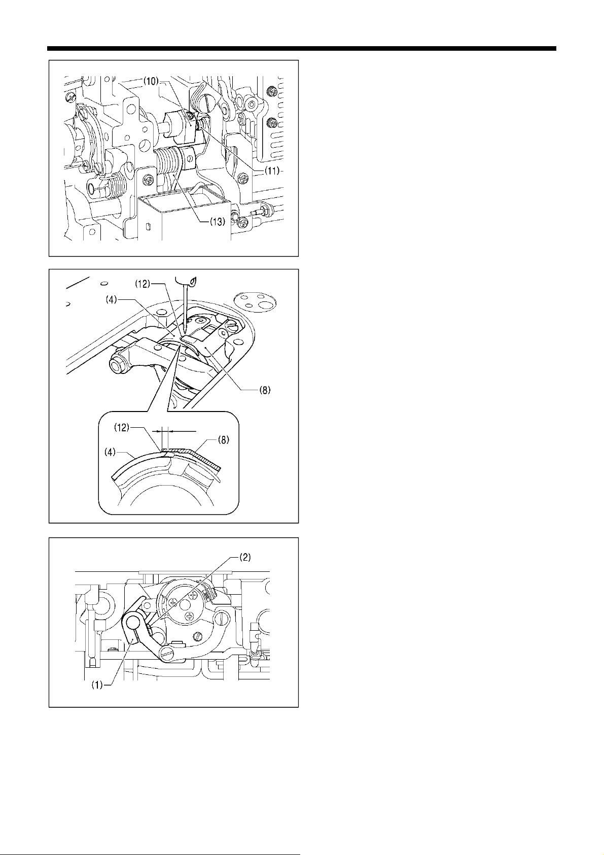
6. STANDARD ADJUSTMENTS
2 mm
1447D
1448D
1445D
7. Turn the machine pulley while the thread trimmer solenoid
is still turned on so that the thread trimmer cam (10) moves
the thread trimmer cam roller (11) to its maximum
displacement position.
* Make sure that the thread trimmer solenoid does not turn
off and does not return during this step.
8. Set the maximum meshing amount for the upper and lower
knives to 2 mm.
* Turn the thread trimmer lever (1) to align the tip of the
upper knife (8) with the center of the index mark (12) on
the lower knife (4).
* Make sure that the tip of the upper knife (8) does not go
past the index mark (12).
9. Tighten the screw (2) of the thread trimmer lever (1).
* Make sure that there is no play in the thrust direction in the
forked shaft (13) of the thread trimmer lever (1) (see
illustration on page 7).
59
S-7250A
Page 69

r
Lowest position
of needle ba
Reference
line (a)
Direction of
cam rotation
- 1.0 mm
0.5 mm
6. STANDARD ADJUSTMENTS
<Thread trimming cam position adjustment>
Raised 6 mm
1. Turn the machine pulley to raise the needle bar 6 mm from
its lowest position (reference line (a) position) so that
reference line (b) is aligned with the bottom edge of the
needle bar bush.
Reference
line (b)
0958D
2. At the above position, push the plunger (1) of the thread
trimming solenoid with your finger in the direction of the
arrow.
Adjust the position of the thread trimmer cam (2) at this
time so that the roller shaft (4) of the thread trimming cam
lever assembly (3) touches the hollow (c) of the thread
trimmer cam (2) and so that the clearance between the
edge of the thread trimmer (2) and the roller (4) is 0.5 to
1.0 mm, and then tighten the set screw (5). (Fig. [A])
3. Check that the edge of the thread trimmer cam (2) and the
roller shaft (4) do not touch when the roller shaft (4) returns
to the right. (Fig. [B])
* Tighten the two set screws (5) to approximately 4 N.m.
Should not touch
1450D
S-7250A
60
Page 70

7. TROUBLESHOOTING
7. TROUBLESHOOTING
・ Please check the following points before calling for repairs or service.
・ Simplified details can be checked on the panel. (Menu → Troubleshooting)
・ If the following remedies do not fix the problem, turn off the power switch and consult a qualified technician or the place of
purchase.
DANGER
Wait at least 5 minutes after turning off the power switch and disconnecting the power cord from the wall outlet
23
23
before opening the control box cover. Touching areas where high voltages are present can result in severe injury.
CAUTION
Turn off the power switch and disconnect the power cord before carrying out these operations.
The machine may operate if the treadle is depressed by mistake, which could result in injury.
7-1. Sewing
Items with a "*" in the "Page" column should only be checked by a qualified technician.
Problem Possible cause Page
1 Upper thread is not tight.
0573M
2 Lower thread is not tight.
0574M
3 Loops appear in seam.
0977M
・ Is the upper thread tension too weak? Is the lower thread tension too
strong?
Adjust the lower thread tension or upper thread tension.
Try pressing the special locus key and selecting No. 1.
・ Is the upper thread tension too strong? Is the lower thread tension too
weak?
Adjust the lower thread tension or upper thread tension.
・ Is the thread path not smooth enough?
Use a file with a fine grain or sandpaper to polish smooth the
thread path.
・ Is the bobbin turning smoothly?
Pull out the lower thread to check that there is no slackness in
the thread tension, or replace the bobbin or bobbin case.
Try pressing the special locus key and selecting No. 1.
4 Skipped stitches occur
while sewing
61
0470M
・ Is the needle tip bent? Is the needle tip blunt?
If the needle tip is bent or blunt, replace the needle.
・ Is the needle properly installed?
If it is incorrect, install the needle correctly.
・ Is the machine properly threaded?
If it is incorrect, thread the thread correctly.
・ Is the presser foot pressure too weak?
Adjust the presser foot pressure.
・ Is the needle too thin?
Replace the needle with a needle that is one rank thicker.
・ Is the presser foot too high?
Adjust the height of the presser foot.
・ Is the thread take-up spring too weak?
Adjust the tension of the thread take-up spring.
・ Is the needle and rotary hook timing correct?
Adjust the height of the needle bar.
Adjust the clearance between the needle and the tip of the
rotary hook.
S-7250A
47
49*
*
51*
53*
Page 71

Problem Possible cause Page
5 Skipped stitches at sewing
start
Thread unraveling at
sewing start.
6 Large bird's nests are
forming at the sewing
start.
0749M
7. TROUBLESHOOTING
・ Is the thread take-up spring tension too strong?
Reduce the tension of the thread take-up spring.
・ Is the thread take-up spring operating range too large?
Lower the position of the thread take-up spring.
・ Is the trailing length of the upper thread too short after thread
trimming?
Adjust the pretension.
・ Are the threads not being trimmed cleanly?
Sharpen the fixed knives, or replace the fixed and movable
knives if necessary. Replace the movable knife.
・ Is the needle too thick?
Replace the needle with a needle that is one rank thinner.
・ Is the length of thread trailing out from the bobbin case after thread
trimming too short?
If the bobbin is spinning loosely, replace the anti-spin spring in
the bobbin case.
・ Is the sewing speed too fast at the sewing start?
Use the slow start key.
・ Is the needle up stop position too high?
Adjust the needle up stop position.
・ Is the upper thread trailing length too short after thread trimming?
Turn on the "Prev. thread away" function.
・ If the thread is pulling out at the sewing start, try the following
remedies.
1. Check the upper thread trailing length.
2. Set the slow start number to "3" or less.
3. Re-adjust the upper thread trailing length to make it longer.
4. Select "Prev. thread away PARA" from "Function setting".
(Refer to "4-6. Setting basic functions".)
(1) Set the 2nd stitch pitch to "3".
(2) Increase the current stitch pitch settings for the 1st and
2nd stitches by about 0.5 to 1.
・ Is the needle hole in the needle plate too large for the needle being
used?
Replace the needle place with one with a needle hole that is
one rank thinner.
・ Is the presser foot groove too wide?
Replace the presser foot with one that has a narrower groove
so that it presses the material at the needle drop position.
・ Is the sewing machine starting to sew before the presser foot has
dropped?
Lower the presser foot before starting sewing.
・ Is the presser foot being raised before the sewing machine has
stopped sewing?
Raise the presser foot after the sewing machine has stopped
sewing.
・ Is the upper thread trailing length too long after thread trimming?
Increase the tension of the pre-tension.
*
*
55*
14・24・29*
25*
24
29*
24
*
S-7250A
62
Page 72

7. TROUBLESHOOTING
Problem Possible cause Page
7 Uneven seam
8 Large degree of puckering
(Thread is too tight)
9 Lower thread is tangled at
the sewing start.
Bobbin is spinning during
thread trimming.
0473M
0978M
Lower
thread
0751M
・ Is the presser foot pressure too weak?
Adjust the presser foot pressure.
・ Is the feed dog too low?
Adjust the feed dog height.
・ Is the bobbin scratched?
If the bobbin is damaged, smooth it with an oiled grindstone or
replace it.
Alternatively, replace the bobbin.
・ Is the upper thread tension too strong?
Make the upper thread tension as weak as possible.
・ Is the lower thread tension too strong?
Make the lower thread tension as weak as possible.
・ Is the needle tip blunt?
Replace the needle if it is blunt.
・ Is the needle too thick?
Replace with as thin a needle as possible.
・ Is the thread take-up spring tension too strong?
Make the thread take-up spring tension as weak as possible.
・ Is the thread take-up spring operating range too large?
Lower the position of the thread take-up spring to as low a
position as possible.
・ Is the presser foot pressure too strong?
Adjust the presser foot pressure.
・ Is the sewing speed too fast?
Gradually reduce the sewing speed.
・ Is the angle of the feed dog correct?
Tilt the front of the feed dog down slightly.
・ Is the bobbin spinning direction correct when the lower thread is
being pulled?
Set the bobbin so that it turns in the opposite direction to the
rotary hook.
・ Is there too much thread
wound onto the bobbin?
The bobbin winding
amount should not be
2124M
more that 80 %.
・ Is the anti-spin spring attached?
Attach the anti-spin spring.
・ Is the bobbin turning smoothly?
If the bobbin is not turning smoothly, replace the bobbin.
・ Is a bobbin other that the light-alloy bobbin specified by Brother being
used?
Use only bobbins which are specified by Brother.
50*
*
*
18*
51*
63
S-7250A
Page 73

Problem Possible cause Page
10 Upper and lower threads
are breaking.
0471M
11 Thread breaks during
backtack sewing.
12 Backtack sewing pitch
varies depending on the
sewing direction.
Backtack edge is not
aligned.
13 Thread tightening around
X-over seam areas.
14 Upper thread is pulling out
of the needle after thread
trimming.
7. TROUBLESHOOTING
・ Is the needle tip bent? Is the needle tip blunt?
If the needle tip is bent or blunt, replace the needle.
・ Is the needle properly installed?
If it is incorrect, install the needle correctly.
・ Is the machine properly threaded?
If it is incorrect, thread the thread correctly.
・ Is the rotary hook sufficiently lubricated?
If the oil gauge is down to the lower reference line in the oil
gauge window, add more oil.
・ Is the upper or lower thread tension too weak or too strong?
Adjust the upper thread or lower thread tension.
・ Is the upper thread may be loose because the thread take-up spring
operating range is too small?
Adjust the position of the thread take-up spring.
・ Is the rotary hook, feed dog or other part damaged?
If the thread path is damaged, smooth it with sandpaper or
similar.
Alternatively, replace the damaged part.
・ Is the thread path damaged?
If the thread path is damaged, smooth it with sandpaper.
Alternatively, replace the damaged part.
・ Is the backtack sewing speed too fast?
Use the panel to reduce the backtack sewing speed.
Adjust using memory switch No. 201. 38*
・ Is the height of the feed dog correct?
Increase the feed dog height.
・ Is the upper thread trailing length after thread trimming appropriate?
Decrease the tension of the pre-tension.
・ Is the thread path not smooth enough?
Use a file with a fine grain or sandpaper to polish smooth the
thread path.
・ Does the thread being used slip easily?
Turn the needle bar bush thread guide D sideways to increase
the resistance.
・ If the upper thread is pulling out of the needle after thread trimming,
check using the method given below.
1. Check the upper thread trailing length.
2. Re-adjust the upper thread trailing length to make it longer.
3. Select "T/T short parameter" from "Function setting". (Refer
to "4-6. Setting basic functions".)
(1) Delete the stitch pitch for the previous stitch.
(2) Decrease the sewing speed for the final stitch and the
stitch before it.
47
6
47*
*
*
19
50*
24*
S-7250A
64
Page 74

7. TROUBLESHOOTING
Problem Possible cause Page
15 Upper thread is raised
above the material surface
after thread trimming.
16 When T/T short is on,
skipped stitches occur
where they should be
sewn at the sewing end.
17 When T/T short is on,
condense stitches (the
final stitch and the one
before it) cannot be sewn
neatly before thread
trimming.
18 Thread trailing length on
underside of material is
too long.
19 When T/T short is on,
thread trailing length on
underside of material is
too short.
20 To prevent fraying at the
sewing end
21 Incorrect thread trimming
(Upper and lower threads
are both not being
trimmed)
・ Upper thread protrudes from the material surface after thread
trimming.
・ Select "T/T short parameter" from "Function setting". (Refer to "4-6.
Setting basic functions".)
1. Increase the pitch during thread trimming.
2. Set the feed direction for sewing end processing to "bw".
・ Use the T/T short parameters to delete the the stitch before the final
stitch.
・ Use the T/T short parameters to reduce the stitch pitch of the final
stitch and the one before it.
・ Use the T/T short parameters to set the feed direction for sewing end
processing to "bw".
If sewing backtack stitches
・ Reduce the number of stitches (D) for backtack sewing by 1 stitch
・ Use the T/T short parameters to increase the stitch pitch.
・ Use the T/T short parameters to reduce the sewing speed.
・ Turn on the T/T short function.
If you would like the trailing length to be even sorter after turning on the
T/T short function.
・ Is the meshing position of the thread trimming knives directly
below the needle hole?
・ Use the T/T short parameters to reduce the stitch pitch of the
condense stitches (the final stitch and the one before it) before
thread trimming.
・ Use the T/T short parameters to reduce the pitch during thread
trimming.
・ Use the T/T short parameters to increase the pitch during
thread trimming.
・ Turn on T/T short processing, and then use the T/T short parameters
to set the feed direction for sewing end processing to "bw".
・ Is the fixed knife or movable knife damaged or worn?
Replace the fixed knife or the movable knife.
・ Is there not enough of a meshing amount between the upper knife
and the lower knife?
Adjust the tip of the upper knife to the lower knife index position
so that the knives mesh.
24*
24*
(65-15)
15*
24*
(65-15)
32*
55*
24*
(65-15)
24*
(65-15)
24*
(65-15)
55*
65
S-7250A
Page 75

Problem Possible cause Page
22 Incorrect thread trimming
(Upper thread is not being
trimmed.)
(Lower thread is not being
trimmed.)
0.1 - 0.3 mm
23 Broken needle
0949D
0469M
7. TROUBLESHOOTING
・ Is the needle properly installed?
If it is incorrect, install the needle correctly.
・ Is the fixed knife or movable knife blunt?
Replace the fixed knife or the movable knife.
・ Tilt the upper knife forward slightly. (About 0.1 to 0.3 mm)
・ Is there not enough of a meshing amount between the upper knife
and the lower knife?
Check that the tip of the upper knife comes to the lower knife
index position so that the knives mesh.
・ Is the material being pushed or pulled with excessive force during
sewing?
・ Is the needle properly installed?
If it is incorrect, install the needle correctly.
・ Is the needle tip bent? Is the needle tip broken, or is the needle hole
blocked?
Replace the needle.
・ Is the needle and rotary hook timing correct?
Adjust the height of the needle bar.
Adjust the clearance between the needle and the tip of the
rotary hook.
・ Is the needle and feed mechanism timing correct?
Adjust to the standard timing.
・ Try pressing the special locus key and selecting No. 2 or No. 3.
NOTE
・ It is extremely dangerous to leave any pieces of broken
needle sticking in the material. If the needle breaks, search
for all pieces until the whole of the needle is found again.
・ Furthermore, we recommend that thorough steps be taken
to account for such needles to comply with product liability
regulations.
55*
53*
*
52*
23
S-7250A
66
Page 76

7. TROUBLESHOOTING
Problem Possible cause Page
24 Machine does not operate
when power is turned on
and treadle is pressed.
25 Machine does not operate
at high speed.
26 Machine stops during
sewing.
27 Nothing appears on the
operation panel display.
28 The illumination becomes
momentarily darker or
flickers.
・ Is the power supply connector
disconnected from the control
box?
Insert the connectors
securely.
1452D
・ Is the sewing speed setting or backtack stitch speed setting too
slow?
Set a higher sewing speed.
・ Is the power supply voltage too low?
Check the power supply voltage.
(If the power cord is too long or too many appliances are being
run from a single outlet, this may cause voltage drops which will
in turn cause the reset function to activate and stop the
machine, even if the power supply itself is normal.)
・ Is the power supply connector
1452D
disconnected from the control
box?
Insert the connectors
securely.
・ Is the operation panel
connector inside the control
box disconnected?
Insert the connectors
securely.
1453D
・ The illumination may become momentarily darker or flicker when the
sewing machine starts or stops, depending on the power supply in
the environment where the sewing machine is being used. This is not
a sign of a malfunction.
11・12
18・19
*
11・12
7
*
67
S-7250A
Page 77

7-2. Error code displays
If an error code appears on the operation panel display
1. Make a note of the error code and then turn off the power.
2. After the operation panel display has turned off, eliminate the cause of the error and then
turn the power back on.
・ Items with a "*" in the "Page" column should only be checked by a qualified technician.
・ For items with "**" appearing in the "Page" column, ask the place of purchase for advice.
<Connector layout diagram>
Sewing machine motor
1454D
connector
Connector P2
Connector P3
S-7250A
7. TROUBLESHOOTING
Connector P1
Connector P4
Connector P6
Connector P7
Connector P5
Power supply
connector
Feed motor connector
1451D
68
Page 78

7. TROUBLESHOOTING
Switch-related errors
Code Cause Remedy
E050
E051
E055
E065
E066
E090
E095
Sewing machine motor-related errors
Code
E111
E112
E113
E130
E131
E132
E133
E140
E150
E151
Machine head is detected as being tilted back when
start sewing.
Machine head is detected as being tilted back
during sewing.
Machine head is detected as being tilted back when
power was turned on.
A disabled key was being pressed when the power
was turned on.
The hand switch was being pressed when the
power was turned on.
Connection of treadle was not detected when
power was turned on.
Treadle or standing operation pedal was being
pressed when power was turned on.
Cause Remedy
The needle up stop position exceeded the specified
value when the sewing machine motor stopped.
The needle up or needle down stop position did not
reach the specified value when the sewing machine
motor stopped.
The needle down stop position exceeded the
specified value when the sewing machine motor
stopped.
Sewing machine motor did not operate at sewing
start or during sewing.
Sewing machine motor encoder connection was not
detected when power was turned on.
Abnormal sewing speed of sewing machine motor
was detected during sewing.
Abnormal signal of sewing machine motor encoder
was detected during sewing.
Sewing machine motor ran in opposite direction to
the direction specified during sewing.
Abnormal overheating detected in sewing machine
motor.
Motor overheating sensor connection was not
detected.
・Turn off the power, and then return the machine
head to its original position.
・Turn off the power and check the connection of
connector P2.
Turn off the power and check the connection of
connector P2.
・Turn off the power, and then return the machine
head to its original position.
・Turn off the power and check the connection of
connector P2.
Turn the power off and then back on again.
* Do not press a disabled key while turning on the
power.
Turn the power off and then back on again.
* Do not press the hand switch when turning on the
power.
Turn off the power and check the connection of
connector P7.
Return treadle unit or standing up operation pedal to
original portion.
* Do not press the treadle or the standing operation
pedal when turning on the power.
Turn off the power and check if the sewing machine
motor or thread trimming mechanism is stiff or not.
Turn off the power and check if the sewing machine
motor or thread trimming mechanism is stiff or not.
Turn off the power and check if the sewing machine
motor or thread trimming mechanism is stiff or not.
・Turn off the power and check if the sewing machine
motor is stiff or not.
・Turn off the power and check the connections of the
sewing machine motor connector and connector
P4.
Turn off the power and check the connection of
connector P4.
Turn off the power and check the connection of
connector P4.
Turn off the power and check the connection of
connector P4.
Turn off the power and check the connection of
connector P4.
Turn off the power and check the sewing conditions.
Turn off the power and check the connection of
connector P4.
E161
E190
E191
69
Sewing machine motor overload was detected
during sewing.
Sewing machine motor was running continuously
for too long during sewing.
Thread trimming solenoid operation was not
completed within the specified period.
S-7250A
Turn off the power and check the sewing conditions.
Turn the power off and then back on again.
Turn off power and check if the thread trimming
mechanism is stiff.
Page 79

Feed mechanism-related errors
Cause Remedy
Code
E210
E211
E251
Communication and memory-related errors
Code
E410
E440
E441
E442
E450
E451
P.C. board-related errors
Code
E700
E701
E705
Feed motor origin is not detected when power is
turned on.
Abnormal feed motor operation detected during
sewing.
Abnormal feed motor overheating detected or feed
motor overheating sensor was not detected.
Cause Remedy
Communication error with panel occurred when
power was turned on.
Data could not be written to the backup memory
(main internal P.C. board).
Data could not be read from the backup memory
(main internal P.C. board).
Back up memory (main internal P.C. board) data
was abnormal, so settings were initialized.
Model settings could not be read from machine
head memory (internal panel).
Data backup cannot be written to machine head
memory (internal panel).
Cause Remedy
Abnormal rise in power supply voltage was
detected when power was turned on.
Abnormal rise in sewing machine motor power
supply voltage was detected.
Abnormal drop in power supply voltage was
detected.
7. TROUBLESHOOTING
・ Turn off the power and check that the feed
mechanism is not abnormal.
・ Turn off the power and check the feed motor
connector and connector P3.
・ Turn off the power and check that the feed
mechanism is not abnormal.
・ Turn off the power and check the feed motor
connector and connector P3.
・Turn off the power and check the sewing conditions.
・Turn off the power and check the connection of
connector P3.
Turn off the power and check the connection of
connector P2.
Turn the power off and then back on again.
Turn the power off and then back on again.
Turn the power off and then back on again.
Turn the power off and then back on again.
Turn the power off and then back on again.
Turn off the power and check the power supply
voltage.
・Turn off the power and check the power supply
voltage.
・Turn off the power and check the connection of
connector P5.
Turn off the power and check the power supply
voltage.
E709
E710
E711
E791
Power supply signal could not be detected when
power was turned on.
Abnormal sewing machine motor current was
detected.
Abnormal feed motor current was detected. Turn off the power and check the connection of
Abnormal solenoid mechanism current detected
when solenoid was activated.
S-7250A
Turn the power off and then back on again.
Turn off the power and check the connection of
connector P4.
connector P3.
Turn off the power and check the connection of
connector P1.
70
Page 80

7. TROUBLESHOOTING
Version updating errors
Cause Remedy
Code
E882
E883
E884
E885
E886
E887
No USB medial connected when power was turned
on.
Version update file could not be detected in USB
media when power was turned on.
Problem with version update file detected during
version updating.
Version update file could not be read from USB
media during version updating.
Problem with version update file detected during
version updating.
Version update file could not be written during
version updating.
Incorrect data written to flash memory. Turn off the power, and then repeat the version
E889
E890
Error occurred during version update. Turn off the power, and then repeat the version
If an error code that is not listed above appears or if carrying out the specified remedy does not solve the problem,
contact the place of purchase.
Turn off the power and check the connection of the
USB media.
Turn off the power and then check that the version
update file is contained in the USB media.
Turn off the power, and then repeat the version
update procedure.
Turn off the power and check the connection of the
USB media.
Turn off the power, and then repeat the version
update procedure.
Turn off the power, and then repeat the version
update procedure.
update procedure.
update procedure.
71
S-7250A
Page 81

8. 7-SEGMENT DISPLAY
8. 7-SEGMENT DISPLAY
S-7250A
72
Page 82

A
INSTRUCTION MANUAL
* Please note that the contents of this manual may differ slightly from the actual product purchased as a result of product improvements.
© 2017 Brother Industries, Ltd. All Rights Reserved.
This is the original instructions.
S-7250
I7081169D E
2017.09.D(3)
 Loading...